Article

The Detection of Soybean Bacterial Blight Based on Polarization Spectral Imaging Techniques

1
Graduate School, Changchun University of Science and Technology, Changchun 130022, China
2
Beijing Institute of Space Mechanics & Electricity, Beijing 100190, China
3
National and Local Joint Engineering Research Center of Space Optoelectronics Technology, Changchun University of Science and Technology, Changchun 130022, China
4
Fundammontal Science on Space-Ground Laser Communication Technology Laboratory, Changchun University of Science and Technology, Changchun 130022, China
5
Key Laboratory of Education Ministry Optoelectronics Measurement & Control and Optical Information Transfer Technology, Changchun University of Science and Technology, Changchun 130022, China
6
School of Physics, Changchun University of Science and Technology, Changchun 130022, China
*
Authors to whom correspondence should be addressed.
Agronomy 2025, 15(1), 50; https://doi.org/10.3390/agronomy15010050
Submission received: 28 November 2024 / Revised: 22 December 2024 / Accepted: 25 December 2024 / Published: 28 December 2024
(This article belongs to the Section Precision and Digital Agriculture)

Abstract

:
Soybean bacterial blight, caused by Pseudomonas savastanoi pv. glycine, which is one of the common diseases of soybeans, has a strong harm and a great impact on the yield of soybeans. If the disease is not diagnosed in time and no solution comes up, it will lead to the serious loss of yield after the disease becomes serious. Therefore, this paper proposes the detection of the soybean bacterial blight with the polarization spectroscopic imaging method, derived from the detection principle and mathematical model of polarization bidirectional reflection distribution function on the basis of the Stokes vector analysis method. By synthesizing the spectral lines of the four polarization states and the non-polarization states, it was found that the physical parameters of I (135°, 90°) polarization state were the most suitable for identifying soybean bacterial blight disease, and other polarization states could also supplement the characteristic information. The results show that the polarization spectral image can effectively identify the polarization characteristics of healthy soybean leaves and early bacterial blight in the field, and can distinguish the healthy leaves and the diseased leaves by obtaining the relative polarization reflectance of different areas in soybean leaves. Finally, the soybean disease species can be accurately diagnosed. This paper provides an optical method for the detection of crop diseases and insect pests, which makes up for the deficiency of the traditional detection technology and can provide a scientific basis for the safe non-destructive detection of crop diseases and pests.

1. Introduction

Soybean is one of the main economic crops in China. Due to the environmental pollution and climatic changes in recent years, soybeans will be affected by some diseases and insect pests in the growth process [1]. Usually, pests and diseases will not only affect the normal growth of crops, but also affect their yield and quality, and even lead to the failure of crop yield. Therefore, the early health state of the soybean must be detected in time after planting soybean plants. The diseases should be detected and solutions should be taken as soon as possible if diseases and insect pests occur, to ensure the healthy growth in the growing period. The conventional detection method of bacterial diseases is usually artificial visual check, through which a disease can only be observed after a period of time of attacks on the crops, and it is difficult to prevent them in advance [2]. Spectral technology has the advantages of fast detection, free from sample preparation, and field detection availability, and has been widely used in biological, chemical, materials, and other fields [3]. In recent years, the use of spectral means to detect crop diseases and insect pests has become a research hotspot in the field of agriculture. Polarization spectral imaging technology is a combination of imaging technology, polarization analysis technology, and spectral technology [4,5,6]. It not only has image resolution ability, but also spectral analysis ability. Using the spectral difference of the composition of the object’s surface to identify and analyze objects has a wide range of application prospects in environmental detection, target recognition, industrial detection, agriculture, and other fields.
V.C. Vanderbilt et al. analyzed the polarization reflection characteristics of crop leaves, and the results included various structural data of crops [7]. In order to detect fusarium head blight (FBI) in wheat grains, Polder G et al. applied a polarizing filter in the visible range and a spectral camera without one in the near-infrared range, and found that the images in the former were more uniform and clearer [8]. Khadabadi reviewed the detection of vegetable diseases and pests based on image processing technology [9]. The Joint Research Laboratory of France established a new infrared imaging system for typical targets in the background of a natural field environment, which verified that the polarization difference between crops and natural background could be used for target recognition [10,11,12]. Pourreza et al. monitored orange groves with polarization multispectral cameras to detect citrus greening diseases in Florida [13]. Alireza Pourreza et al. used polarization imaging technology to trace the gray values of images at different positions of infected citrus leaves and proposed an image analysis algorithm. This method successfully detected any increase in local gray values related to starch accumulation in the images of citrus plants infected with yellow dragon disease to detect the existence of class clusters, so as to treat the infected plants in a timely manner [14,15]. Alexia Gobrecht et al. analyzed sunflower leaves based on a polarization hyperspectral in vivo detection imaging system and achieved good results, and pointed out that this study has considerable application prospects [16]. Adam J. Blake et al. used the polarization method to identify host plants and non-host plants and showed that DoLP reflected from the leaf surface is an important plant clue, which may be widely used by insect-eating insects [17]. Krzystof Beć et al. studied and analyzed the principles and applications of vibration spectral imaging in plant science, introduced the general perspective of vibration spectral imaging microspectroscopy from the perspective of plant research, and revealed the potential and limitations of spectral technology [18]. Knight found through his research that Chinese cabbage has a unique absorption of polarized light [19]. Wenjing Zhu et al. made an effective judgement on the nutritional stress of tomatoes by using polarization spectrum and hyperspectral data fusion technology, and improved the prediction accuracy of spectral diagnosis technology in precision agriculture [20]. Yao Peng and Mary et al. further fused spectral and spatial information by changing the polarization direction and environmental lighting angle and combining the multi-spectral imaging system made by the spectral camera. The system could distinguish the characteristics of healthy cassava and plants inoculated with cassava brown streak disease for 28 days [21]. Li Siyuan et al. used polarization multispectral imaging technology and vegetation fusion detection algorithm to effectively detect the health status of outdoor plants [22]. Xu Jiayi et al. used polarization spectrum technology to identify data parameters of jujube and showed that the technology could predict the growth state of jujube trees through data correction [23].
In conclusion, by studying the polarization and spectral characteristics of objects, a series of scientific problems such as crop growth state, pest detection, and agricultural remote sensing can be solved, and the ability of target recognition can be significantly improved. By combining the polarization characteristics and spectral characteristics of the target, more information can be obtained to distinguish the target and improve the recognition ability. In this paper, soybean plants are taken as the research object, the polarization spectral image recognition method is used to detect the early disease of soybean bacterial blight, and a brand new method is proposed for the diagnosis of soybean disease. This method has the advantages of fast speed, accuracy, no destructiveness and cheap equipment, and can be applied to the disease to protect the healthy growth of soybean plants to provide scientific research support for precision agriculture and smart agriculture.

2. Materials and Methods

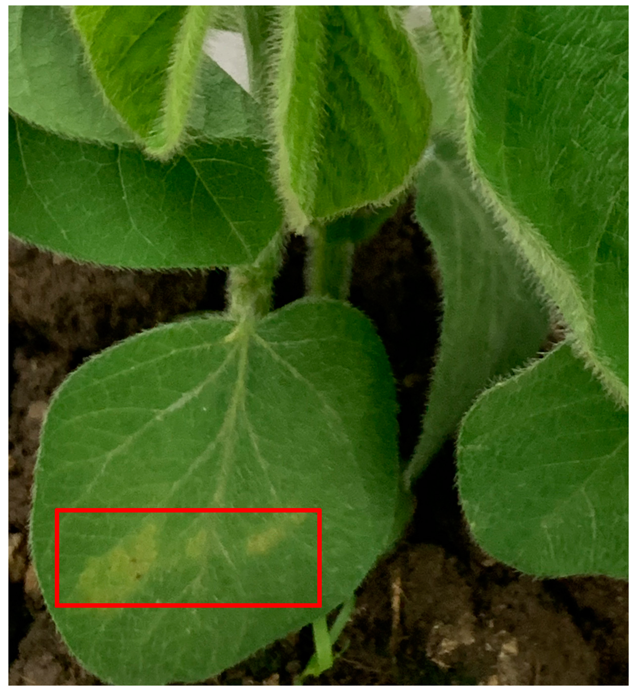
2.1. Source of Disease Object

As shown in Figure 1, the soybean seeds of “Jiyu 47” cultivated in 2021 were selected to be planted and cultivated in the experimental field of Jilin Agricultural University (longitude 125.38475, latitude 43.811835, Changchun, Jilin Province of China) in 2022. The infected soybean plants were taken as sample objects to determine the early samples of soybean bacterial blight. In order to ensure the same growth environment of healthy soybean samples and infected soybean plants, pesticides and growth agents were not used from the early to the late growth stage, so as to ensure the identity of each sample and the scientific nature of the experiment. In the early stage of infected soybean plants, 10 soybean bacterial blight plants were labelled, each infected plant was labelled with a number, and then polarization spectral image detection was carried out.

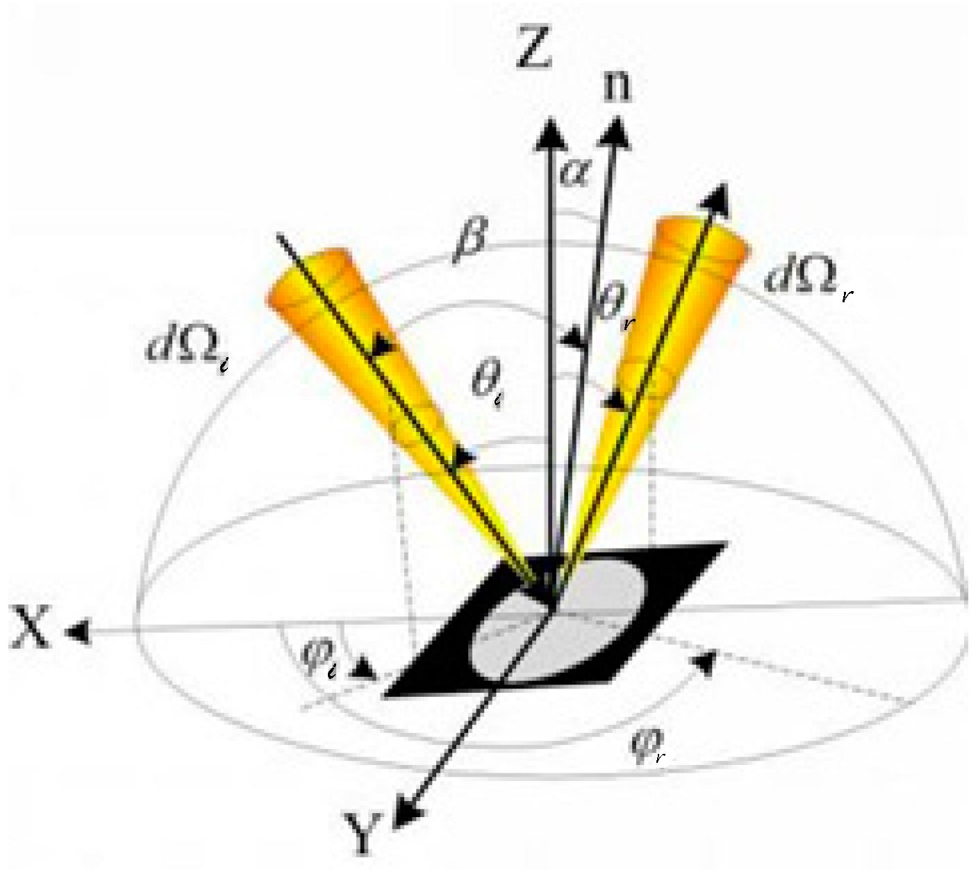
2.2. pBRDF Detection Method of Polarization Reflection Spectrum of Target Surface

In this study, the polarization bidirectional distribution function (pBRDF) theory was used to complete the establishment of an experimental measurement platform, in order to accurately and scientifically obtain the polarization reflection spectrum image of soybean leaves. Soybean leaves have a complex surface. In order to characterize the polarization characteristics of the target and analyze the reverse process of scattering characteristics, pBRDF is used to analyze the light system between the incident and reflected light. Figure 2 shows the geometric path in the pBRDF model.
I, Q, U, and V, the four Stokes vectors of incident light, can be expressed as follows [16]:
I Q U V = S 0 i n S 1 i n S 2 i n S 3 i n = 1 8 π σ 2 1 cos 4 α exp ( ( tan 2 α / 2 σ 2 ) ) cos ( θ i ) 2 cos 2 ( η i ) a s s 2 + 2 sin 2 ( η i ) a p p 2 d Ω I b g 1 8 π σ 2 1 cos 4 α exp ( ( tan 2 α / 2 σ 2 ) ) cos ( θ i ) cos ( 2 η r ) 2 cos 2 ( η i ) a s s 2 2 sin 2 ( η i ) a p p 2 d Ω I b g 1 8 π σ 2 1 cos 4 α exp ( ( tan 2 α / 2 σ 2 ) ) cos ( θ i ) sin ( 2 η r ) 2 sin 2 ( η i ) a s s 2 + 2 cos 2 ( η i ) a p p 2 + cos ( 2 η r ) sin ( 2 η i ) ( a ss a p p * + a s s * a p p ) 1 8 π σ 2 1 cos 4 α exp ( ( tan 2 α / 2 σ 2 ) ) cos ( θ i ) 2 i sin ( 2 η i ) ( a ss a p p * a s s * a p p ) d Ω I b g
In the above Equation (1), I is the radiation intensity of incident light under the unit area in the experimental device; Q and U are the direction and intensity of linearly polarized light in the incident light. V is the circular polarization parameter and Ibg is the background light intensity. Please refer to the supporting documents for detailed derivation of the formula. The formula can be used to describe the real-time polarization information characteristics of the leaf [24]. It is found that there are many factors affecting the polarization state of the measured leaf, such as the refractive index of the leaf surface, biological texture state, background light intensity, the angles of incident light and reflected light, etc. To sum up, the influence of the above factors should be fully considered when building the experimental acquisition device.

2.3. Multi-Dimensional Fusion Image Information Extraction Method

The polarization spectrum detection technology can obtain three types of information about the target: spectral information, spatial distribution information, and polarization information, but the target data obtained synchronously include seven dimensions of physical parameters ( λ is spectral one-dimensional information; x , y is spatial two-dimensional information; S 0 , S 1 , S 2 , S 3 is polarization parameter four-dimensional information).
In each band of polarization spectral image, the corresponding mathematical expression can be used to describe as S 0 , λ S 1 , λ S 2 , λ S 3 , λ D O L P λ D O C P λ O r i e n t λ , λ = 1,2 , 3 N . Each spectral band in the spatial distribution of the polarization spectrum is proportional to an axis, and the relationship between axes is mutually orthogonal. Then, the target information of the DN value of any pixel in the image is described by a matrix as follows:
D a t a = s p S 0 , s p S 1 , s p S 2 , s p S 3 , s p D O L P , s p D O C P , s p O r i e n t
In the above formula, s p r = s p p 1 s p p 2 s p p i s p p k , p S 0 , S 1 , S 2 , S 3 , D O L P , D O C P , O r i e n t . DOLP is the degree of linear polarization, DOCP is the degree of circular polarization, and orient is the direction of polarization angle. The single column corresponds to the K-dimension vector, respectively, and the element in the formula is the polarization relative reflectance value of the spectral segment (polarization spectrum).
In the sample to be tested, a 5 × 5 pixel region is selected to extract the polarization spectrum data and draw the polarization spectrum curve. The relative polarization spectral reflectance R p r is introduced in this paper, and the expression is as follows:
R p r = ( I 0 I B ) ( I W I B )
In Formula (3), I 0 is the average light intensity value of the feature region of the original image of the sample; I B is the average light intensity value of the real-time black image completely covered by the lens of the polarization spectral imaging system; and I W is the average light intensity value of the white reference image obtained by collecting the standard white polyethylene plate (about 98% reflectivity). In conclusion, the relative reflectance of the characteristic region under a certain polarization state and wavelength after correction can be obtained by the above formula.

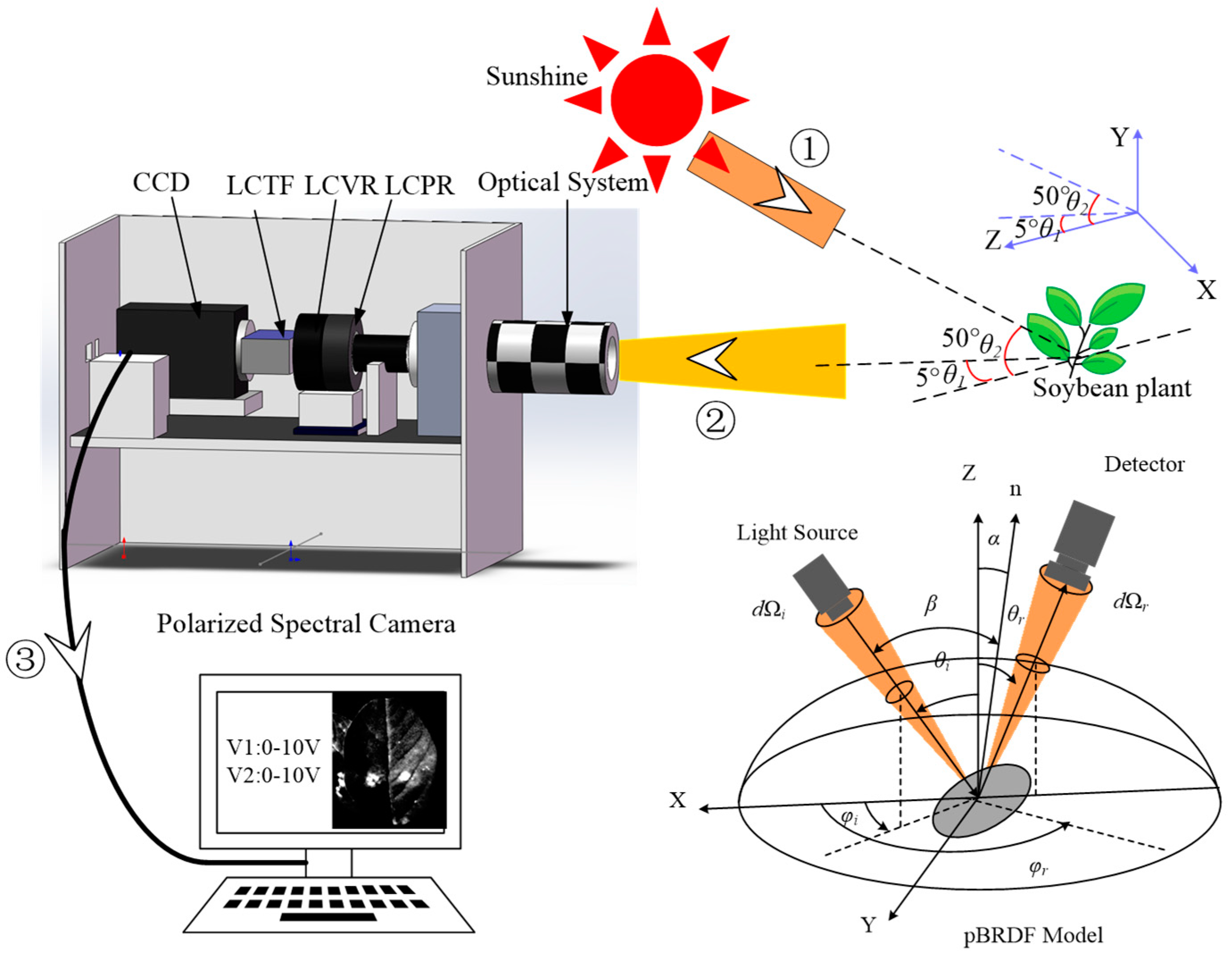
2.4. Experimental Device and Process

The polarization-spectral imager used in this study is made up of a focus lens (Canon (China) Co., Ltd., Beijing, China.), a parallel light tube frame, a liquid crystal phase retarder LCVR (Meadowlark Optics, Inc., Located in Boulder, CO, USA.), a liquid crystal polarization rotator LCPR (Meadowlark Optics, Inc.), a liquid crystal tunable filter LCTF (Cambridge Research & Instrumentation, Cri, Woburn, MA, United States.), and a CCD detector (Hamamatsu Photonics Corporation, Hamamatsu City, Shizuoka Prefecture, Japan). The detected frame rate of this device ≤100 fps; the polarization angle resolution is 1; the spectral bandwidth is 7, 10, or 20 nm; the detection distance ≤50 m; and the spectral coverage range is 400–720 nm. See the supporting document Tables S1–S3 for more detailed parameters of the instrument.
Figure 3 is the test spectrum of LCTF transmittance. It can be seen from the figure that the overall transmittance increases with the increase in wavelength, but the transmittance is only 10% at 440 nm. The transmittance is relatively stable at 520–550 nm, remaining at 34%. The transmittance remains at 43% in the range of 560–640 nm. The transmittance reached the highest value of 61% in the wavelength range of 650–710 nm.
As shown in Figure 4, the polarization-spectral imager was first aimed at the leaves of the diseased plants, and the lens was adjusted to confirm the region of interest. Secondly, the operation was carried out according to the following process: (1) the Sun’s beam shines on the soybean leaf surface, (2) it is reflected to the CCD detector in the spectral imager, (3) the received light beam is converted into a digital charge signal, which is output by the computer in the form of pictures and videos; finally, the polarization spectrum imaging recognition research is carried out. Multiple frame frequencies and different polarization parameters were used to detect the same region. In order to ensure the optimal imaging effect and the consistent position of the acquired images, the experiment was conducted when the angle θ 1 formed by the imager and the leaf surface normal line was 5° and the solar altitude angle θ 2 was 50° in the XZ plane. Xenon lamps were used instead of solar sources in the laboratory experiments. The position relationship between the illumination and detection is based on the principle of BRDF bidirectional reflection distribution model, as shown in the lower right corner of Figure 4.
At the early growth stage of each group of samples, the polarization spectral imaging method was used to collect the data on the diseased and healthy parts of soybean leaves. In the process of data acquisition, the solar altitude angle might change, and there would be some errors in the data. Therefore, the unpolarized state and four different polarization state images of each group of samples should be processed by software, and the polarization image and polarization spectrum of samples should be extracted and analyzed in detail, so as to obtain the polarization spectrum characteristics of soybean diseases.

3. Results and Discussion

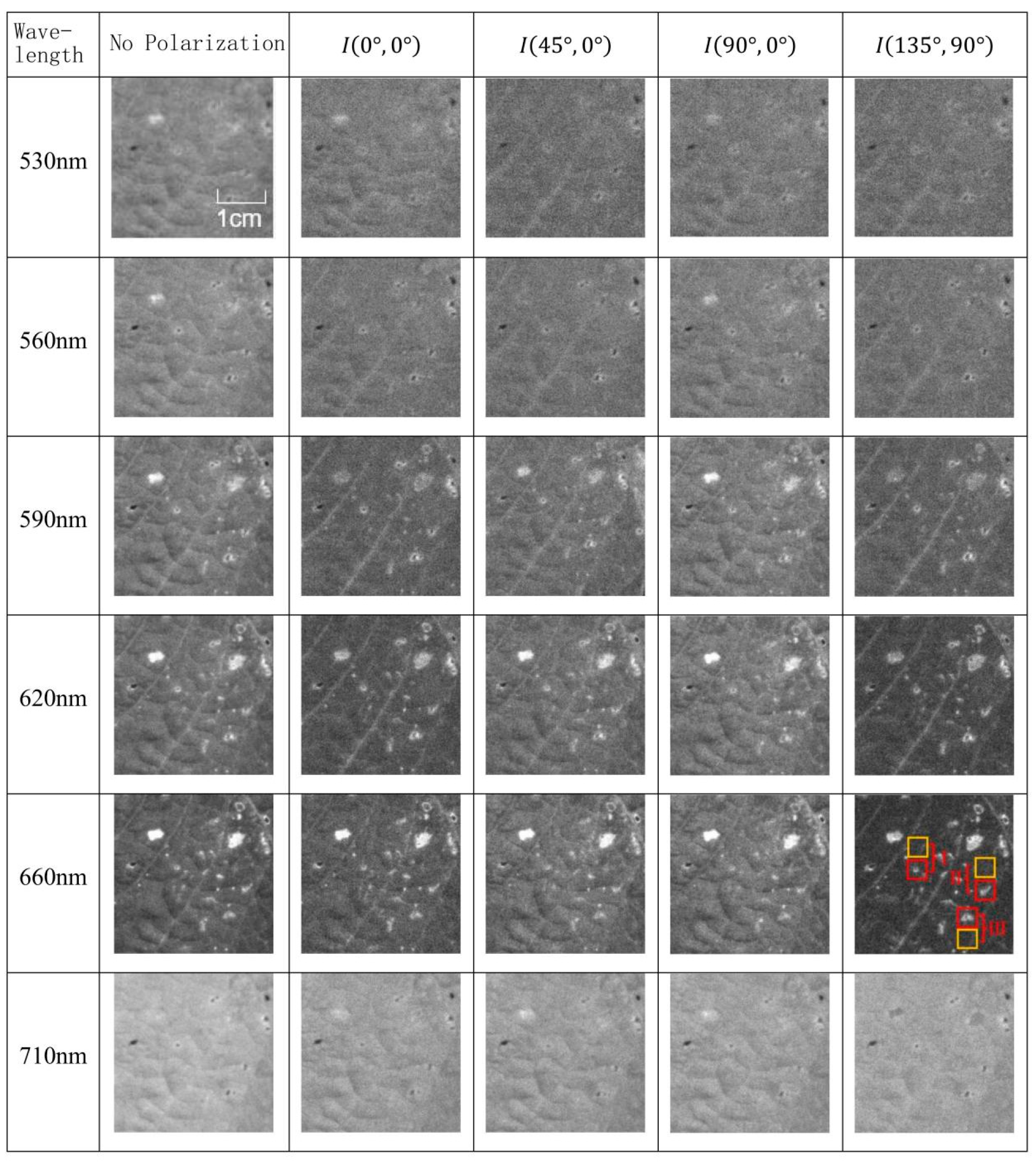
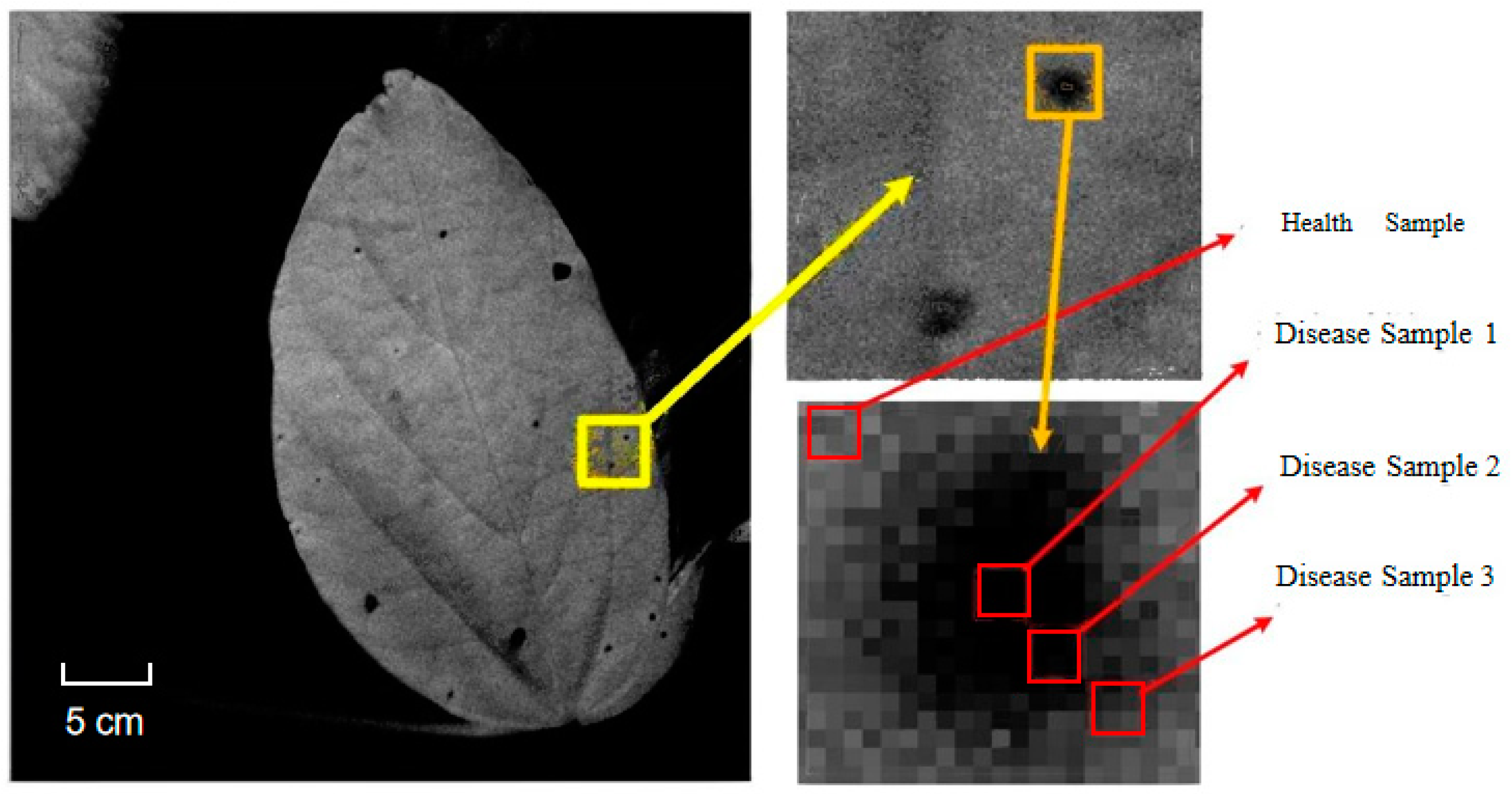
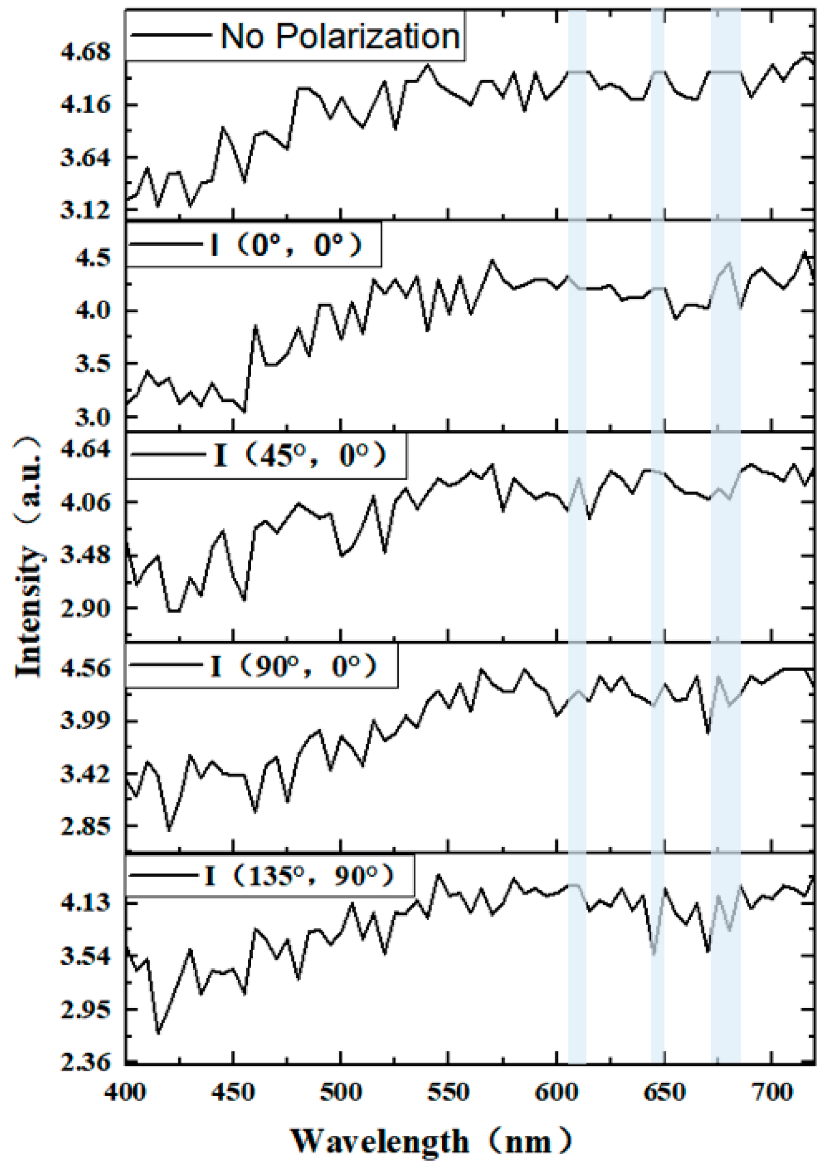
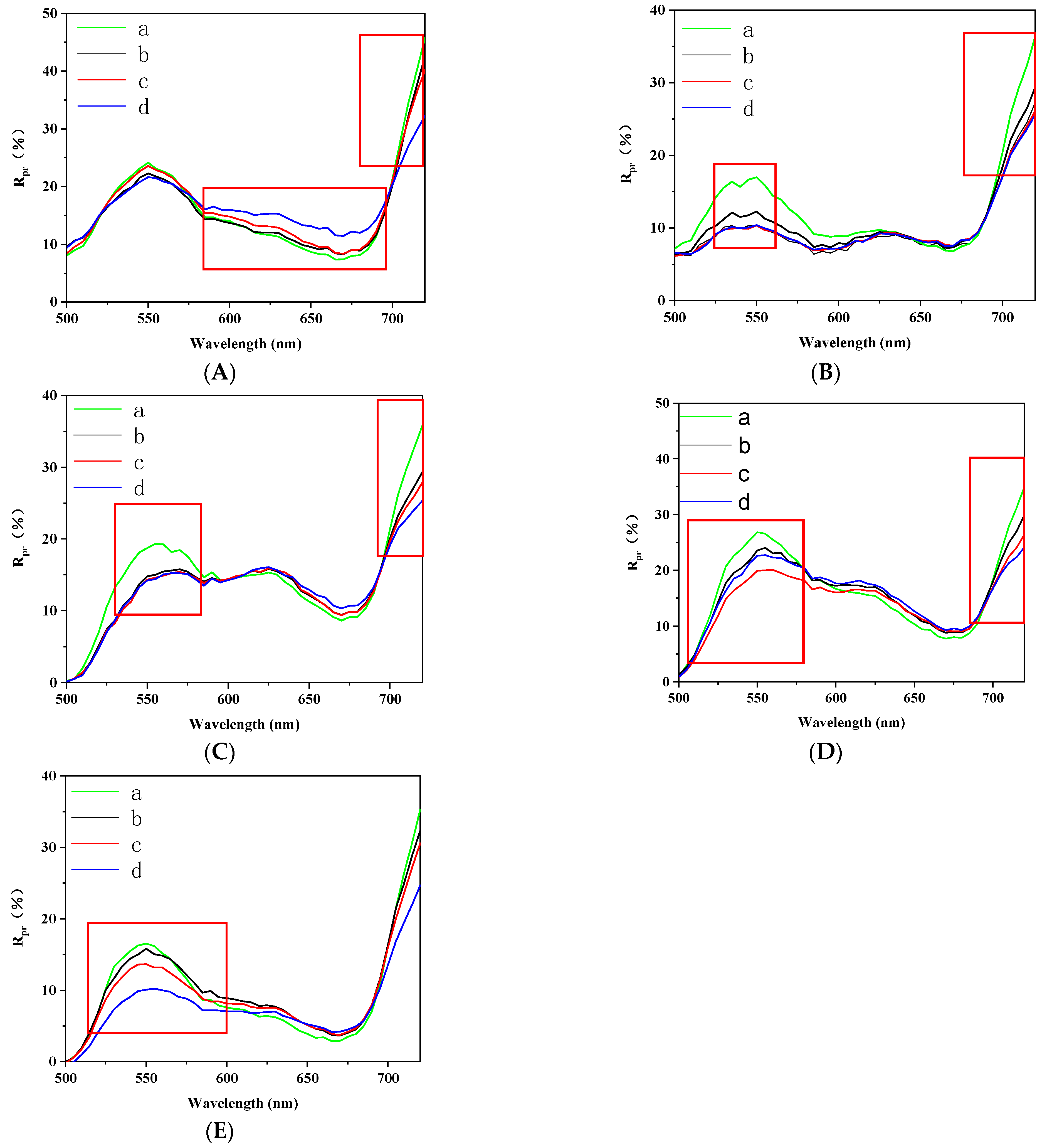
Analysis of Polarization Spectrum Characteristics of Diseased Leaves

The early images of soybean bacterial blight taken by the camera are shown in Figure 5. It can be found that the spots on the leaves in the early stage are light green, and there are some yellows around the spots. With the growth of the plants, the spots will turn black in color and the spots will spread and become larger. Therefore, early detection of the disease is very critical to its drug prevention and control. Polarization spectral imaging is one of the effective methods to detect early soybean bacterial blight free from destruction.
The polarization spectrometer possesses a spectrum measurement range of 400–720 nm with a measurement interval of 5 nm, resulting in 65 distinct images in different bands. After accounting for the transmittance of LCTF, the polarization images exhibiting characteristic wavelengths of 530 nm, 560 nm, 590 nm, 620 nm, 660 nm, and 710 nm are ultimately chosen for analysis.
Figure 6 shows the polarization spectrum images and non-polarization spectrum images of soybean bacterial blight leaves under four outdoor polarization states. Since the spectrum coverage range of the polarization spectrometer is 400–720 nm, taking 5 nm as a step forward, there will be 65 images in different bands. Considering the transmittance of LCTF, the polarization images with characteristic wavelengths of 530 nm, 560 nm, 590 nm, 620 nm, 660 nm, and 710 nm are finally selected for analysis. According to the images under four different outdoor polarization states in the following figure, it can be seen that the leaf’s diseased area shows irregular black spots in the image. Compared with light green spots taken by ordinary cameras, the surface features of the disease are more prominent, making it easier for early diagnosis.
Soybean bacterial blight plants identified by outdoor polarization spectral imager were dug up with roots and soil, put into flowerpots, and sent back to the laboratory for indoor detection. Since outdoor detection inevitably involves atmospheric disturbances and light intensity interference, indoor darkroom sealing detection of plants was conducted to ensure the absence of wind and to fix the intensity and angle of the light source.
Figure 7 shows the polarization spectral images of soybean bacterial blight leaves in four polarization states in different wavebands and the spectral image not in polarization state, the filtering range is 500–590 nm, and the brightness of the image is darker. When the LCTF filter reaches 620 nm, the luminous flux increases and the image has a tendency to shine, but the disease features are not obvious. At this time, in the non-polarized state, the effect of the overall spectral image of the leaves is relatively bright, the disease feature highlighting ability is insufficient, and the white spot is relatively obvious and difficult to be distinguished from the bacterial spot. In the polarization state images I 45 ° , 0 ° of 590–620 nm, it can be found that the white spots have obvious differences in texture characteristics compared with the non-polarization images. The white spots are not diseased spots but caused by other factors and have nothing to do with disease. The gray inside of the white spots in the polarization images I 135 ° , 90 ° can distinguish them from diseased spots more clearly. Compared with the images taken by ordinary cameras in Figure 4, polarization images play a stronger role in the characterization of feature and non-feature regions. Polarization images at 620–710 nm represent the fiber texture information more clearly than those at 590 nm, and the disease speckle is most prominent at 660 nm in polarization I 135 ° , 90 ° state. In contrast to other polarization states and non-polarization states, the spot halo was clear, and the early bacterial blight characteristics could be clearly distinguished. No white spots can be seen at 710 nm without polarization state, while white spots can be clearly seen in images observed in polarization state I 135 ° , 90 ° . White spots can be avoided and healthy regions can be effectively taken when selecting healthy points in the detection region, so as to determine the health state of the plant.
As shown in Figure 8, since the disease encroaches on soybean plants from the diseased spots on leaves, each region of the diseased spots has different characteristics, and the halo of a diseased spot is divided into three regions: the inner, middle, and outer regions. Therefore, the images collected from the diseased leaves are divided into disease sampling 1, disease sampling 2, and disease sampling 3, representing the inner, middle, and outer of the diseased area, respectively. The principle of taking health sampling points is to take points adjacent to the disease sampling points, and take a 5 × 5 pixel matrix for each point region. In the growth environment of soybean plants, each leaf has a different canopy and is in a different growth environment. If different leaves are used to compare and analyze the diseased part and the healthy part, the data will be inaccurate. Therefore, in this paper, both the diseased part and the healthy part are tested in the same leaf. Three disease sampling areas and three health areas adjacent to the disease sampling areas were selected for each disease leaf. As shown in Figure 7, the positions of I, II, and III in the red box are disease spot areas, while the positions of the adjacent yellow box are healthy areas. Each disease spot area includes the inner, middle, and outer disease sampling regions. On the left is the spectral image without polarization. Since the veins are different in texture from other parts of the leaf, in order to avoid the uniformity of sampling points and the reliability of data, no sampling points are carried out at the veins. This method of using polarization-spectral image recognition is based on a physical analysis of disease characteristics, resulting in patterns represented by physical parameters with strong contrast and higher than the measured mean.
The information indices of the images of the inner, middle, and outer disease sampling regions were evaluated by the information entropy function. The software MATLAB 2012b was used for data processing during the calculation, and the results are shown in Figure 9. It can be seen from the spectral lines that the unpolarized spectral lines in the region of the information entropy disease spots have the same intensity values in the ranges of 605–615 nm, 645–650 nm, and 670–685 nm. Because there is no polarization information in these three intervals in the unpolarized state, the image cannot produce different characteristic information with the changes in the wavelength. It can be seen that more information can be reflected in different polarization states.
According to the polarization and non-polarization spectrum images, the relative reflectance in the images can be extracted for comparative analysis. The detection range was of 400–720 nm in the same polarization state and the relative reflectance was calculated according to Formula (3). In the non-polarization state and I 0 ° , 0 ° , I 45 ° , 0 ° , I 90 ° , 0 ° , and I 135 ° , 90 ° state, the relative reflectance spectra of the soybean leaf with bacterial blight are as shown in Figure 10.
Figure 10 shows the relative reflectance spectra of leaves with bacterial blight in four polarization states and non-polarization states. a is the average relative reflectance spectral lines of health sampling 1, health sampling 2, and health sampling 3, and b is the average relative reflectance spectral lines of the outer regions of disease sampling 1, disease sampling 2, and disease sampling 3. c is the average relative reflectance spectral lines of the middle regions of disease sampling 1, disease sampling 2, and disease sampling 3, and d is the average relative reflectance spectral lines of the inner regions of disease sampling 1, disease sampling 2, and disease sampling 3.
Since the spectral images in the range of 400–500 nm are dark and not able to display the feature information, the relative reflectance of polarization in the range of 500–720 nm is extracted. It can be seen from the spectral lines that the non-polarized state is relatively consistent with the relative spectral reflectance emitted from the four polarization states, and the overall linear trend of the spectral lines is consistent, which proves that the experimental platform and the light source are stable at the identified location.
As shown in Figure 10A, in the non-polarized state, the inner disease spots in the range of 585–695 nm were larger than the other three regions, and the highest point was greater than 3%, but the middle and outer disease spots could not be well distinguished from the healthy sampling points, and the spectral lines were almost the same. In the range of 700–720 nm, the relative reflectance of the spectral lines increased from the inner to the outer regions of the disease spots in turn. Among them, the most significant difference in reflectance between the inner region of the disease spot and other areas is 7%.
As shown in Figure 10B, in the range of 530 nm–560 nm, polarization state I 0 ° , 0 ° , the relative polarization reflectance of the health sampling point is greater than that of the disease sampling point at the highest point by 6%, and the spectral line peak of the health region is obvious, which can be used as the characteristic peak to distinguish the healthy from the diseased, but the inner, middle, and outer parts of the disease spot cannot be distinguished from each other in this polarization state. In the range of 695–720 nm, the maximum relative reflectance of the healthy region was 7% greater than that of the outer region of the disease spot, which could clearly distinguish the healthy and the diseased spot, but the middle and the inner disease spots could not be distinguished in this range. As shown in Figure 10C, in the I 45 ° , 0 ° polarization state, a characteristic peak appeared in the health sampling point in the range of 560–570 nm, and the polarization reflectance was greater than 4% at the highest point of the three sampling points of the diseased. In the range of 700–720 nm, there was a significant intensity difference in the four regions, showing a descending linear relationship between the relative reflectance of the health point to the inner disease spot, and the different regions of the disease spot could be diagnosed in this range. As shown in Figure 10D, in the polarization state I 90 ° , 0 ° , the characteristic peak appeared at 520–580 nm, and the reflectance of the healthy region was greater than that of the highest point of the outer of the disease spot by 3%. That of the outer was greater than that of the inner disease spot, and that of the inner was greater than that of the outer disease spot. There were obvious intensity differences in the four regions in the range of 695–720 nm, which was the same as that in the polarization state I 45 ° , 0 ° . This can be used as a characteristic spectrum segment to diagnose different regions of disease. As shown in Figure 10E, in the polarization state of I 135 ° , 90 ° , the characteristic peak appears at 505–565 nm, and the spectral line in this range is the most significant among all polarization states, and the band range is the longest. It can be seen that the polarization reflectance is smaller the closer to the region inside the disease spot is, so the spectral characteristics of the disease spot region can be reflected here. By synthesizing the spectral lines of the four polarization states and the non-polarization states, it was found that the physical parameters of I 135 ° , 90 ° polarization state were the most suitable for identifying soybean bacterial blight disease, and other polarization states could also supplement the characteristic information.

4. Conclusions

In this paper, polarization-spectral images of outdoor and indoor soybean leaf bacterial blight disease were obtained by using polarization-spectral imaging recognition technology, and the relative reflectance of different regions of the disease spot was extracted. The field detection of crop diseases is more complex, and this study provides a basis for field experiments and data support for drone-mounted spectrometers. Further in-depth research is still underway. From the contrast analysis of polarization spectral image features and relative reflectance spectral line features, soybean bacterial blight disease can be effectively diagnosed. The new diagnostic method proposed in this paper can be applied in the field, so that the scientific research in the laboratory can be applied in the field, and then extended to civilian use, so as to protect precision agriculture in China.

Supplementary Materials

The following supporting information can be downloaded at: https://www.mdpi.com/article/10.3390/agronomy15010050/s1, Figure S1: Geometric path diagram of PBRDF model; Table S1: LCTF effective parameter index; Table S2: CCD effective parameter index; Table S3: LCPR effective parameter index.

Author Contributions

Conceptualization, H.J.; methodology, H.J.; formal analysis, J.Y.; investigation, Y.T.; data curation, J.Y.; data collection, J.Y.; writing—original draft preparation, J.Y.; supervision, Y.T.; final revision of the manuscript: J.Y. All authors have read and agreed to the published version of the manuscript.

Funding

This paper is supported by Natural Science Foundation of Jilin Province under No. YDZJ202201ZYTS510.

Data Availability Statement

The original contributions presented in the study are included in the article, and further inquiries can be directed to the corresponding author.

Conflicts of Interest

The authors declare no conflicts of interest.

References

  1. Williams, D.J.; Nyvall, R.F. Leaf infection and yield losses caused by brown spot and bacterial blight diseases of soybean. Dis. Detect. Crop Losses 1980, 70, 900–902. [Google Scholar] [CrossRef]
  2. Sotelo, J.P.; Rovey, M.F.P.; María, E.C.; Moliva, M.V.; Oliva, M.D.L.M. Characterization of Pseudomonas syringae strains associated with soybean bacterial blight and in vitro inhibitory effect of oregano and thyme essential oils. Physiol. Mol. Plant Pathol. 2023, 128, 102133. [Google Scholar] [CrossRef]
  3. Zahra, A.; Qureshi, R.; Sajjad, M.; Sadak, F.; Nawaz, M.; Khan, H.A.; Uzair, M. Current advances in imaging spectroscopy and its state-of-the-art applications. Expert Syst. Appl. 2024, 238, 122172. [Google Scholar] [CrossRef]
  4. Wang, X.Y.; Li, Y.; Pan, T.; Zhang, Z.G.; Qu, J.Q.; Sun, Y.Z.; Zhao, H.J.; Miao, L.X.; Hu, Z.B.; Zhao, Z.M.; et al. Diagnosis of soybean bacterial blight progress stage based on deep learning in the context of data-deficient. Comput. Electron. Agric. 2023, 212, 108170. [Google Scholar] [CrossRef]
  5. El-Esawi, M.A.; Ali, H.M.; Hatamleh, A.A.; Al-Dosary, M.A.; El-Ballat, E.M. Multi-functional PGPR Serratia liquefaciens confers enhanced resistance to lead stress and bacterial blight in soybean (Glycine max L.). Curr. Plant Biol. 2024, 40, 100403. [Google Scholar] [CrossRef]
  6. Zhao, F.Z.; Wang, Y.A.; Cheng, W.; Antwi-Boasiako, A.; Yan, W.K.; Zhang, C.T.; Gao, X.W.; Kong, J.J.; Liu, W.S.; Zhao, T.J. Genome-wide association study of bacterial blight resistance in soybean. Plant Dis. 2024. [Google Scholar] [CrossRef]
  7. Vanderbilt, V.C.; Grant, L.; Daughtry, C.S.T. Polarization of light scattered by vegetation. Proc. IEEE 1985, 73, 1012–1024. [Google Scholar] [CrossRef]
  8. Polder, G.; Van Der Heijden, G.W.A.M.; Waalwijk, C.; Young, I.T. Detection of Fusarium in single wheat kernels using spectral imaging. Seed Sci. Technol. 2005, 33, 655–668. [Google Scholar] [CrossRef]
  9. Khadabadi, G.C.; Rajpurohit, V.S.; Kumar, A.; Nargund, V.B. Disease detection in vegetables using image processing techniques: A review. Int. J. Emerg. Technol. Comput. Sci. Electron. 2015, 14, 954–960. [Google Scholar]
  10. Vannier, N.; Goudail, F.; Plassart, C.; Boffety, M.; Feneyrou, P.; Leviandier, L.; Bertaux, N. Active polarimetric imager with near-infrared laser illumination for adaptive contrast optimization. Appl. Opt. 2015, 54, 7622–7631. [Google Scholar] [CrossRef] [PubMed]
  11. Vannier, N.; Goudail, F.; Plassart, C.; Boffety, M.; Feneyrou, P.; Leviandier, L.; Bertaux, N. Comparison of diffez‘ent active polarimetric imaging modes for target detection in outdoor environment. Appl. Opt. 2016, 55, 2881–2891. [Google Scholar] [CrossRef]
  12. Vannier, N.; Goudail, F.; Plassart, C.; Boffety, M.; Feneyrou, P.; Leviandier, L.; Bertaux, N. Infrared active polarimetric imaging system controlled by image segmentation algorithms: Application to decamouflage. Spie Commer. Sci. Sens. Imaging 2016, 9853, 98530. [Google Scholar]
  13. Pourreza, A.; Lee, W.S.; Etxeberria, E.; Zhang, Y. Identification of citrus Huanglongbing disease at the pre-symptomatic stage using polarized imaging technique. IFAC-Pap. 2016, 49, 110–115. [Google Scholar] [CrossRef]
  14. Pourreza, A.; Lee, W.S.; Raveh, E.; Ehsani, R.; Etxeberria, E. Citrus Huanglongbing detection using narrow-band imaging and polarized illumination. Trans. ASABE 2014, 57, 259–272. [Google Scholar]
  15. Sarkar, S.K.; Das, J.; Ehsani, R.; Kumar, V. Towards autonomous phytopathology: Outcomes and challenges of citrus greening disease detection through close-range remote sensing. In Proceedings of the 2016 IEEE International Conference on Robotics and Automation (ICRA), Stockholm, Sweden, 16–21 May 2016; IEEE: New York, NY, USA, 2016; pp. 5143–5148. [Google Scholar]
  16. Xu, J.L.; Gobrecht, A.; Héran, D.; Gorretta, N.; Coque, M.; Gowen, A.A.; Sun, D.W. A polarized hyperspectral imaging system for in vivo detection: Multiple applications in sunflower leaf analysis. Comput. Electron. Agric. 2019, 158, 258–270. [Google Scholar] [CrossRef]
  17. Blake, A.J.; Go, M.C.; Hahn, G.S.; Grey, H.; Couture, S.; Gries, G. Polarization of foliar reflectance: Novel host plant cue for insect herbivores. Proc. R. Soc. B 2019, 286, 20192198. [Google Scholar] [CrossRef]
  18. Beć, K.B.; Grabska, J.; Bonn, G.K.; Popp, M.; Huck, C.W. Principles and applications of vibrational spectroscopic imaging in plant science: A review. Front. Plant Sci. 2020, 11, 1226. [Google Scholar] [CrossRef] [PubMed]
  19. Knight, K. Cabbage whites have a unique take on polarized light. J. Exp. Biol. 2020, 223, jeb230441. [Google Scholar] [CrossRef]
  20. Zhu, W.; Li, J.; Li, L.; Wang, A.; Wei, X.; Mao, H. Nondestructive diagnostics of soluble sugar, total nitrogen and their ratio of tomato leaves in greenhouse by polarized spectra–hyperspectral data fusion. Int. J. Agric. Biol. Eng. 2020, 13, 189–197. [Google Scholar] [CrossRef]
  21. Peng, Y.; Dallas, M.M.; Ascencio-Ibáñez, J.T.; Hoyer, J.S.; Legg, J.; Hanley-Bowdoin, L.; Yin, H. Early detection of plant virus infection using multispectral imaging and spatial–spectral machine learning. Sci. Rep. 2022, 12, 3113. [Google Scholar] [CrossRef] [PubMed]
  22. Li, S.; Jiao, J.; Wang, C. Research on polarized multi-spectral system and fusion algorithm for remote sensing of vegetation status at night. Remote Sens. 2021, 13, 3510. [Google Scholar] [CrossRef]
  23. Xu, J.Y.; Luo, H.P.; Suo, Y.T.; Chen, C.; Li, W.; Wang, C.X. Application of Polarization Spectral in NDT of Jujube Leaves. Xinjiang Agric. Mech. 2021, 23–26. [Google Scholar] [CrossRef]
  24. Ye, Y.; Tan, Y.; Jin, G.Y. Accurate measurement for damage evolution of ceramics caused by nanosecond laser pulses with polarization spectrum imaging. Opt. Express 2019, 27, 16360–16376. [Google Scholar] [CrossRef] [PubMed]
Figure 1. Soybean experimental field.
Agronomy 15 00050 g001
Figure 2. Geometric path of pBRDF model.
Agronomy 15 00050 g002
Figure 3. Spectrum of LCTF transmittance test.
Agronomy 15 00050 g003
Figure 4. Polarization-spectral image acquisition experimental device.(① The sample is irradiated with sunlight.② The scattered light from the sample is transmitted to the detector.③ The detector is connected to the computer via a cable.)
Agronomy 15 00050 g004
Figure 5. Image of soybean bacterial blight taken by an ordinary camera. (The red rectangle indicates the diseased area.)
Agronomy 15 00050 g005
Figure 6. Spectral images of soybean bacterial blight leaves with four polarization states and no polarization state under different outdoor wavebands (The red box indicates the area affected by the disease).
Agronomy 15 00050 g006
Figure 7. Spectral images of soybean bacterial blight leaves in four polarization states and no polarization states in different indoor wavebands (The red box indicates the area affected by the disease, while the yellow box indicates the healthy area).
Agronomy 15 00050 g007
Figure 8. Leaf image sampling of soybean bacterial blight (The red boxes highlight positions 1, 2, and 3 as areas of disease lesions. Each disease lesion area includes the interior, edge, and exterior of the disease sample, with adjacent areas being healthy).
Agronomy 15 00050 g008
Figure 9. Comparison of spectral lines of different polarization states in the disease spot under the information entropy function.
Agronomy 15 00050 g009
Figure 10. Relative reflectance spectra of leaf with bacterial spot disease in non-polarized state (A), I 0 ° , 0 ° state (B), I 45 ° , 0 ° state (C), I 90 ° , 0 ° state (D), and I 135 ° , 90 ° state (E). (a is the average relative reflectance of the three relatively healthy areas, b is the average relative reflectance outside the three disease spots, c is the average relative reflectance in the three disease spots, and d is the average relative reflectance in the three disease spots).
Agronomy 15 00050 g010
Disclaimer/Publisher’s Note: The statements, opinions and data contained in all publications are solely those of the individual author(s) and contributor(s) and not of MDPI and/or the editor(s). MDPI and/or the editor(s) disclaim responsibility for any injury to people or property resulting from any ideas, methods, instructions or products referred to in the content.

