Article

Fast Camera Analysis of Plasma Instabilities in Hall Effect Thrusters Using a POD Method under Different Operating Regimes

1
Laboratoire de Physique des Plasmas, CNRS, Ecole Polytechnique, Sorbonne Université, Université Paris-Sud, Observatoire de Paris, Université Paris-Saclay, PSL Research University, F-91128 Palaiseau, France
2
Laboratoire de Physique, University Lyon, Ens de Lyon, University Claude Bernard, CNRS, F-69342 Lyon, France
*
Author to whom correspondence should be addressed.
Current address: DPHY, ONERA, Université Paris Saclay F-91123 Palaiseau, France.
Current address: CAPS Laboratory, Department of Mechanical and Process Engineering, ETH Zurich, 8092 Zurich, Switzerland.
Atmosphere 2020, 11(5), 518; https://doi.org/10.3390/atmos11050518
Submission received: 9 April 2020 / Revised: 11 May 2020 / Accepted: 13 May 2020 / Published: 18 May 2020

Abstract

:
Even after half a century of development, many phenomena in Hall Effect Thrusters are still not well-understood. While numerical studies are now widely used to study this highly non-linear system, experimental diagnostics are needed to validate their results and identify specific oscillations. By varying the cathode heating current, its emissivity is efficiently controlled and a transition between two functioning regimes of a low power thruster is observed. This transition implies a modification of the axial electric field and of the plasma plume shape. High-speed camera imaging is performed and the data are analysed using a Proper Orthogonal Decomposition method to isolate the different types of plasma fluctuations occurring simultaneously. The low-frequency breathing mode is observed, along with higher frequency rotating modes that can be associated to rotating spokes or gradient-induced instabilities. These rotating modes are observed while propagating outside the thruster channel. The reduction of the cathode emissivity beyond the transition comes along with a disappearance of the breathing mode, which could improve the thruster performance and stability.

1. Introduction

In the last decade, the number of satellites orbiting around Earth has grown exponentially. For various applications (orbital station-keeping, collision avoidance, etc.), a propulsion system is needed aboard these satellites. Electric propulsion appears to be the best option and ion-gridded thrusters along with Hall-Effect Thrusters (HET) are now routinely used [1,2]. The latter are known from the 1960s and have been successfully used in space (for example, the Safran PPS-1350 on the ESA SMART-1 mission to the moon, in 2003), but, despite extensive studies [3,4,5], the physics of these thrusters is still not well-understood.
In these devices, a neutral gas, often Xenon, is injected through an anode ring located at the back of an annular discharge channel. The gas is ionised by electrons emitted by a cathode located at the exit of the channel (see Figure 1b). A potential difference is imposed between the anode and cathode to sustain the discharge. The resulting axial electric field, E, accelerates the ions to produce thrust. At the low pressures used (typically of the order of 10 3 mbar or less), the ionisation mean free path is orders of magnitude larger than the thruster length, and hence a radial magnetic field B is needed to confine the electrons and increase the ionisation efficiency up to 90% [6].
HET have historically been developed in the 1-kW power range [7] with typical discharge voltages of a few hundred volts and currents of several amps. Decades of experience have improved these thrusters to make them highly efficient. However, from the diversity of space missions stems the need of widening the thruster power capabilities. High-power thrusters are needed for deep-space missions, while low-power thrusters could be used on small satellites. Due to a lack of knowledge on HET physics, these scalings are currently done empirically (trial and error method), which limits the efficiency of the newly developed thrusters and increases the development time and cost.
As described by Choueri [8], a wide range of instabilities can arise and interact inside a HET. They originate from the presence of diverse gradients, in multiple directions [9]. The HET discharge is hence difficult to analyse due to this highly non-linear behaviour. Many experimental [10,11,12,13,14], numerical [15,16,17] and theoretical [18,19,20] studies have been conducted on these instabilities but more insights are still needed. The current effort made towards developing predictive models [21,22,23] is limited by the axial electron mobility that cannot be derived self-consistently [24]. Understanding this so-called anomalous electron transport is the main current challenge. As it has been found to be related with kinetic effects [20], Particle-In-Cell (PIC) simulations are the best numerical tool to study this transport [16,25,26]. However, even though a recent effort has been made on the cross-verification of PIC codes [27], more work is needed towards their validation against experimental data. Moreover, current experimental diagnostics need to be improved as the experimental uncertainties are still too large to help the derivation of first-principles models [28]. Overall, while numerical simulations give important insights, the development of new experimental diagnostics is still of uttermost importance.
For these reasons, this study aimed at diagnosing a low power HET. The studied thruster is a 500 W PPS-type HET prototype developed by Safran, operated in Xenon, with a simple Thoriated-Tungsten filament cathode. The typical discharge voltage is 200 V with a gas flow rate of 1.8 mg·s 1 . This kind of low-power thruster has been scarcely studied experimentally thus far [29,30]. In this work, we combined the use of a high-speed camera that can acquire images up to 900 kfps with the Proper Orthogonal Decomposition (POD) image analysis method [31] to extract characteristics of the unstable regimes developing in the plasma. The focus was made on two main instabilities: the low-frequency breathing mode, in the kHz range, that develops axially and is related to the neutral gas dynamics [32,33] and rotating modes, with a frequency around ten times higher, that propagate in the azimuthal E × B direction [34,35] and could be related to rotating spokes [36] or gradient-induced instabilities [37]. It appears that these rotating modes are not only located near the anode but propagate in the thruster plume.
Depending on the filament cathode emissivity, two different regimes have been observed: a nominal regime where the cathode is emissive enough so that the heating current of the cathode does not affect the discharge current and an under-emissive regime where the discharge current is strongly driven by the cathode heating current. These two regimes exhibit different oscillating behaviours. Front and side videos of the thruster along with the POD analysis allow us to isolate the two aforementioned oscillations and bring insights on the properties of each regime. It is important to mention that we study here a current limited transition of the discharge regime through a magnetic barrier. This is quite an original work as it is usually the magnetic field that is taken as the driving parameter for this type of transition, both in HET functioning regime analysis [38,39,40,41] and in fundamental and fusion studies [42,43,44,45]. Moreover, in the under-emissive regime, the breathing mode disappears and only rotating modes are observed, which could affect the performances of the thruster.
First, a description of the experimental set-up is given, along with more details about the POD algorithm. Then, the results for different working regimes are given, depending on the cathode heating current I H . The observed instabilities are finally analysed and discussed for each of these regimes.

2. Materials and Methods

2.1. The Hall Effect Thruster

The thruster channel is a 30-mm-long cylinder with an inner diameter of 30 mm and an outer diameter of 50 mm. The walls are dielectric, made of BNSiO 2 . An electric field E is created along the channel by a power supply imposing a potential difference between a cathode, located in front of the channel, and an anode, at the back of the channel. Five coils (one in the centre and four on the corners) generate a radial magnetic field B (see Figure 1a). The electrons emitted by the cathode, in addition to their movement in the opposite direction to the field E , hence undergo a drift in the azimuthal direction E × B , causing a circular global drift current within the ejection channel. Xenon atoms (Xe) injected as a gas at the entrance of the channel, are then ionised by collisions with this circular current of electrons. This phenomenon gives birth to the ions Xe + (mainly) and Xe 2 + (very few) [46]. These ions are accelerated by the axial electric field E , which produces the thrust. The typical value of the ejection speed of the ions at the exit of the thruster is 15,000 m.s 1 [47].
The presence of the radial magnetic field B , with a maximum of around 150 G, has very little influence on the trajectory of the ions since their Larmor radius is much larger than the characteristic size of the thruster. However, because of their lower mass, the electrons are strongly magnetised in the discharge channel so the magnetic field has a major impact on their dynamics. Therefore, the field B acts as a magnetic barrier for electrons and drastically increases the total length of the path followed by an electron from the cathode to the anode. In this way, the probability of collision (e , Xe) is maximised, allowing the ionisation of the plasma, with the least possible disturbance on ion acceleration.
The thruster has a typical regime characterised by a Xenon mass flow rate Q, a discharge voltage U d and a discharge current I d . The mass flow rate Q has been kept fixed at 1.8 mg·s 1 for this study, but can be varied from 1.2 to 2.1 mg·s 1 . The discharge voltage U d has been kept equal to 200 V but can be varied from 100 to 350 V, giving discharge currents I d typically between 1 and 3 A.
The cathode, made of three tungsten wires doped with 1% of Thorium, is heated by an electric current I H . Several wires are set in parallel because it drastically extends the lifetime of the cathode; however, it also increases the necessary heating current. The cathode is immersed in an electric field, experimentally generated and controlled by the discharge voltage U d , that ‘tears off’ thermionic electrons to feed the thruster discharge and neutralise the ion beam.

2.2. Vacuum Chamber

The thruster is ignited inside a vacuum chamber composed of a large 6-way cross with flange of 350-mm diameter, as shown in Figure 1b. On the thruster axis, a 4-way cross corresponds to the second part of the chamber. Each port of this cross is 260-mm diameter. This leads to a total of 7 large accesses for the pumps, the cathode and needed optical access or diagnostics. The total length of the experimental set-up along the thruster axis is 900 mm. Three turbo-pumps with a combined pumping speed of 5060 L·s 1 for pure N 2 are used. The base pressure is about 1 × 10 7 mbar while, with a Xenon mass flow rate of 1.8 mg·s 1 , the background pressure is about 4 × 10 4 mbar ( 1.6 × 10 4 Xenon corrected pressure).The authors are aware that this pressure is quite high compared to previous experiments [48] but it is not unusual and the background pressure effects should not affect the physics analysed here [49].

2.3. Fast Frame Camera, Data Acquisition

The high-speed camera used to capture videos of the thruster is a Photron FastCam SA-Z 2100 K. This camera is able to record 20,000 frames per second (fps) at full frame resolution of 1024 × 1024 pixels, and goes up to 2.1 million fps with a reduced resolution of 128 × 8 pixels. In our context, videos have been acquired at three different frame rates: 3 × 10 5 fps with a 256 × 128 pixels resolution, 4.8 × 10 5 fps with a 128 × 80 pixels resolution and 9.0 × 10 5 fps with a 128 × 56 pixels resolution. Hence, a very suitable spatial resolution of the observed phenomenon is provided at low acquisition rate, but is slightly reduced when increasing the temporal resolution. Each pixel has a 12-bit dynamical range and the light intensity is given in counts between 0 and 4096.
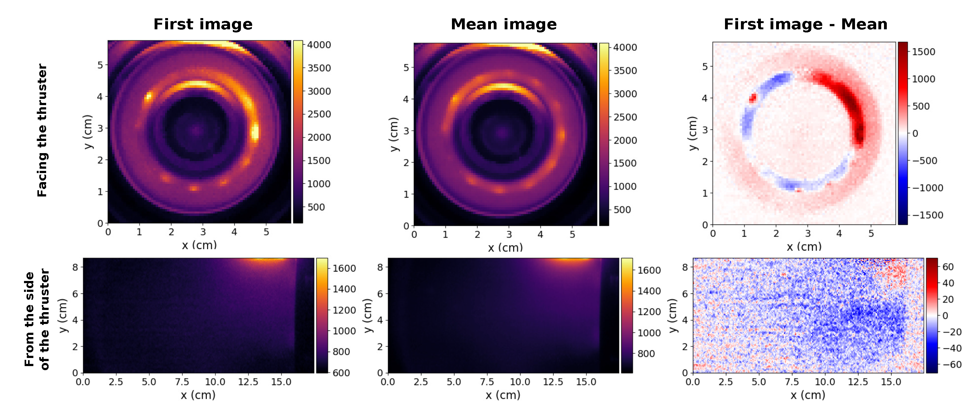
Videos were taken both facing the thruster (Figure 2 top row) and from the side of the thruster (Figure 2 bottom row). Front videos can capture all the light emitted from the plasma in the plume and inside the thruster channel down to the anode, whereas only the thruster plume is imaged with side videos. The raw images were used to compute temporal averaged images (over the corresponding acquisition length varying from 1.5 to 2.5 ms, depending on the acquisition frequency) displayed in the middle column of Figure 2. On the front images, one can recognise the two concentric ceramic walls delimiting radially the discharge channel. On the side images, the thruster is on the right-hand side of the frame, with the plume extending to the left. On both these images, the maximum of captured light is located at the top, where the cathode stands. In fact, the cathode is very bright with respect to the plasma which makes the camera hard to position. The mean image is then subtracted to each image of the movie to improve the analysis on the oscillatory regime of the thruster (right column of Figure 2). The POD analysis is applied to this last set of images, as described in the next section.
As only one fast camera is available to do these experiments, the front and side videos were acquired separately. An effort was made to have reproducible experimental conditions but POD modes singular values and exact oscillation frequency may vary from a dataset to another.
The authors acknowledge that light emission measured with a fast camera cannot be taken as a direct measurement of any plasma parameter. The light fluctuations, integrated over the full spectrum, are only a proxy for plasma density. The correlation between these two figures is very good only when electron temperature and neutral density fluctuations are negligible [50,51], which has not been demonstrated in the case of HETs. A strictly quantitative analysis of the light emitted by a plasma would then require a calibration, which can be led for example with a Langmuir probe or a full collisional radiative model. Best correlations are then obtained when only a short wavelength range is selected, for example using an interference filter with a narrow bandwidth at the camera entrance. Only photons emitted by the plasma at a given electronic transition are then acquired. In our case, the acquisition time is too small to use this type of filter and light from the full spectrum will be used. Given these restrictions, the relative amplitudes and typical frequencies of the different oscillation regimes observed later in the manuscript are representative of the fluctuations phenomena occurring in the plasma but no quantitative analysis on the plasma density fluctuations amplitudes can be performed.

2.4. POD Analysis Routine

To analyse the movies acquired with the high speed camera and isolate dominant physical modes of the plasma dynamics, a Proper Orthogonal Decomposition (POD) routine was implemented. This method was first introduced in the early 1900s by Pearson [52] and then developed by several researchers including Kosambi (1943) [53], Loève (1945), Karhunen (1946), Pougachev (1953), Obukhov (1954) and E N Lorenz (1965). It is thoroughly described in the book by Lumley [54] for fluid dynamics applications. The main idea of this technique is to decompose a real valued video signal v : x Ω , t T v ( x , t ) R defined over the pictures 2D space Ω and acquired over the temporal interval T as a linear combination of so-called POD modes p i ( x , t ) = λ i u i ( x ) w i ( t ) :
v ( x , t ) = i λ i u i ( x ) w i ( t ) .
Space and time are decoupled as a product of spatial POD modes u i ( x ) and temporal POD modes w i ( t ) , both normalised, and weighted by the modes’ amplitude λ i > 0 named ’singular values’. Indeed, both { u i } and { w i } are asked to be orthonormal families with respect to their corresponding inner product · Ω over space Ω and · T over time T:
u i , u j Ω = Ω u i ( x ) u j ( x ) d x = δ i j and w i , w j T = T w i ( t ) w j ( t ) d t = δ i j
Applying · Ω onto Equation (1) enables us to think p i ( x , t ) as the spatial projection of the frame v ( x , t ) over u i at a given time t and derive w i ( t ) from this projection:
p i ( x , t ) = u i ( x ) v ( · , t ) , u i Ω
v ( · , t ) , u i Ω = λ i w i ( t )
A natural inner product · Ω × T over space and time can be carried out, defining λ i as the L 2 norm of the POD mode p i , that turns out to be orthogonal with the other modes thanks to the orthonormality condition asked in Equation (2):
p i , p j Ω × T = Ω × T p i ( x , t ) p j ( x , t ) d x d t = δ i j λ i 2
In the discrete case of a video of N T images, each image having M Ω pixels, the POD can be performed efficiently when N T M Ω (typically, in our case, N T 10 3 and 64 × 64 M Ω 256 × 128 ) using the method of snapshots introduced by Sirovich [55]. This method consists in converting the video into a matrix A, called snapshots matrix, of size M Ω × N T whose nth column A n is the vectorised image v ( x , t n ) at time t n computed over points { x m } 1 m M Ω :
time : N T columns A : = ( v ( x 1 , t 1 ) v ( x 1 , t N T ) v ( x M Ω , t 1 ) v ( x M Ω , t N T ) ) } space : M Ω rows
The POD method then derives from a Singular Value Decomposition (SVD) of this matrix. Indeed, let us suppose the SVD decomposition of the matrix A to be given as follows: A = U Σ W T where U M M Ω , r ( R ) and W M N T , r ( R ) are orthogonal matrices, with r = rank ( A ) . Σ = ( δ i j λ i ) M r , r ( R ) is here a definite positive diagonal matrix. Defining u i and w i such that u i ( x m ) = U i m and w i ( t n ) = W i n leads us to the expected form of Equation (1), respecting the orthonormality properties in Equation (2):
v ( x m , t n ) : = A m n = i = 1 r j = 1 r U m i Σ i j W j n T = i = 1 r j = 1 r U m i δ i j λ i W n j = i = 1 r λ i U m i W n i = i = 1 r λ i u i ( x m ) w i ( t n )
As shown in Equation (6), the POD can be achieved from a SVD simply in un-vectorising the columns of U (respectively, W) to obtain the spatial (respectively, temporal) POD modes u i (respectively, w i ), while the singular values λ i are listed in Σ diagonal. To perform efficiently the SVD on the snapshots matrix A of size M Ω × N T , where N T M Ω , a well known method called thin SVD consists in computing the orthogonal diagonalisation of the smaller positive definite matrix A T A of size N T × N T [56]. This method is used by most SVD algorithms and makes the POD a very efficient tool to decompose large set of images onto their main components.
Because the video remains in a finite-dimensional space, the decomposition in Equation (1) appears to be exact, with a finite number of POD modes that is exactly equal to r, the rank of A. However, what if fewer modes are taken? Which one should be chosen to best fit v? As explained in [31], the POD computation can be seen as trying to find an orthonormal family { u i } optimal for reconstructing the video signal the most efficiently. To understand how, let us try to approximate v ( x , t ) by an arbitrary given family of n frames u ^ 1 , , u ^ n supposed to be orthonormal. It is easy to show that, for a given instant t, the closest frame ν { u ^ i } 1 i n ( x , t ) of v ( x , t ) spanned by this family is:
ν { u ^ i } 1 i n ( x , t ) : = arg min ν S p a n ( u ^ 1 , , u ^ n ) v ( · , t ) ν Ω 2 ( x ) = i = 1 n u ^ i ( x ) v ( · , t ) , u ^ i Ω
The optimality property of the POD claims that for every dimension n 1 , r , the family of spatial POD modes { u i } 1 i n , indexed such that λ 1 λ 2 λ n > 0 , minimises the approximation residual:
v ν { u ^ i } 1 i n Ω × T 2 v ν { u i } 1 i n Ω × T 2 = v i = 1 n p i Ω × T 2 = i = n + 1 r λ i 2
In other words, when averaging over time, the family { u i } 1 i n spans the optimal subspace of dimension n in which to approach the signal v ( x , t ) .
As shown by Equation (8), the singular value distribution { λ i } 1 i r carries in itself the system propensity to be reduced in a lower dimension. Moreover, it plays no mean part in the uniqueness of POD modes determination. Indeed, any orthonormal family of A T A eigenvectors raised by the thin SVD computation is admissible to be a temporal POD modes family. The corresponding spatial POD modes are uniquely derived from this family. As is well known, a real symmetric matrix with only distinct eigenvalues has a unique basis of orthonormal eigenvectors up to a ± 1 factor, regardless of their order. Nevertheless, in the case of a multiple eigenvalue, every orthogonal transformation of its corresponding eigenvectors is another admissible decomposition. Hence, the POD modes { p i } are uniquely defined if and only if their singular value distribution { λ i } is not degenerated, while their space-time decompositions ( u i , w i ) are always defined up to a ± 1 factor. Since the video v ( x , t ) stems from a physical acquisition, it is fairly certain that the matrix A T A has no multiple eigenvalues in practice, not even 0. Therefore, in the sense described previously, the POD is unique.
Thus, the POD catches in unique way ’natural modes’ stemming from the system dynamics which are by essence uneven in space and in time. This is a pro in the first analysis of a physical phenomenon but can be a con in a comparison between experiment and theoretical descriptions usually using Fourier transform decomposition of an oscillatory phenomenon.
The results of this technique applied to the HET plasma framing are presented in the following section.

3. Results

3.1. Cathode Emissivity and Thruster Operating Regime

The cathode, sometimes called the neutraliser, is an electron emitter based on the principle of thermionic electron emission. It is located outside of the discharge channel. Part of the electrons emitted are entering the discharge channel to ionise the neutral gas before being collected at the anode. The rest of them are neutralising the ion flux in the thruster plume. Cathodes are usually made of a ceramic compound (BaO or LaB6) that has a very low work function. A heater made of a resistive conductor is used to bring the temperature of the ceramic typically above 1000 K. A keeper is biased with respect to the emissive material to produce a discharge, fuelled by a neutral gas flow independent from the anodic one. The overall electrical circuit (emissive material and keeper) is biased with respect to the anode to create the axial electric field in the HET discharge. Once the discharge has started, the heater is usually turned off and the ceramic temperature is self-sustained by the discharge process. This type of cathode (so-called hollow cathodes) is very efficient in an industrial process but is quite cumbersome in a laboratory experiment.
In this work, a simpler cathode was used. It is made of a single Tungsten filament doped by 1% of Thorium that is heated using a DC current, I H . The filament is directly biased with respect to the HET anode. No gas flow is then necessary which simplifies the process but makes the HET more difficult to ignite. Electrons are emitted from the hot filament. The maximum discharge current that can be extracted from this cathode follows a Richardson law [57], describing thermionic emission:
I e m = A e f f A G T w 2 exp e W k b T W ,
with A e f f the effective area of the cathode, A G the Richardson constant, T W the temperature of the filament, e the elementary charge, W the work function of the cathode material and k b the Boltzmann constant.
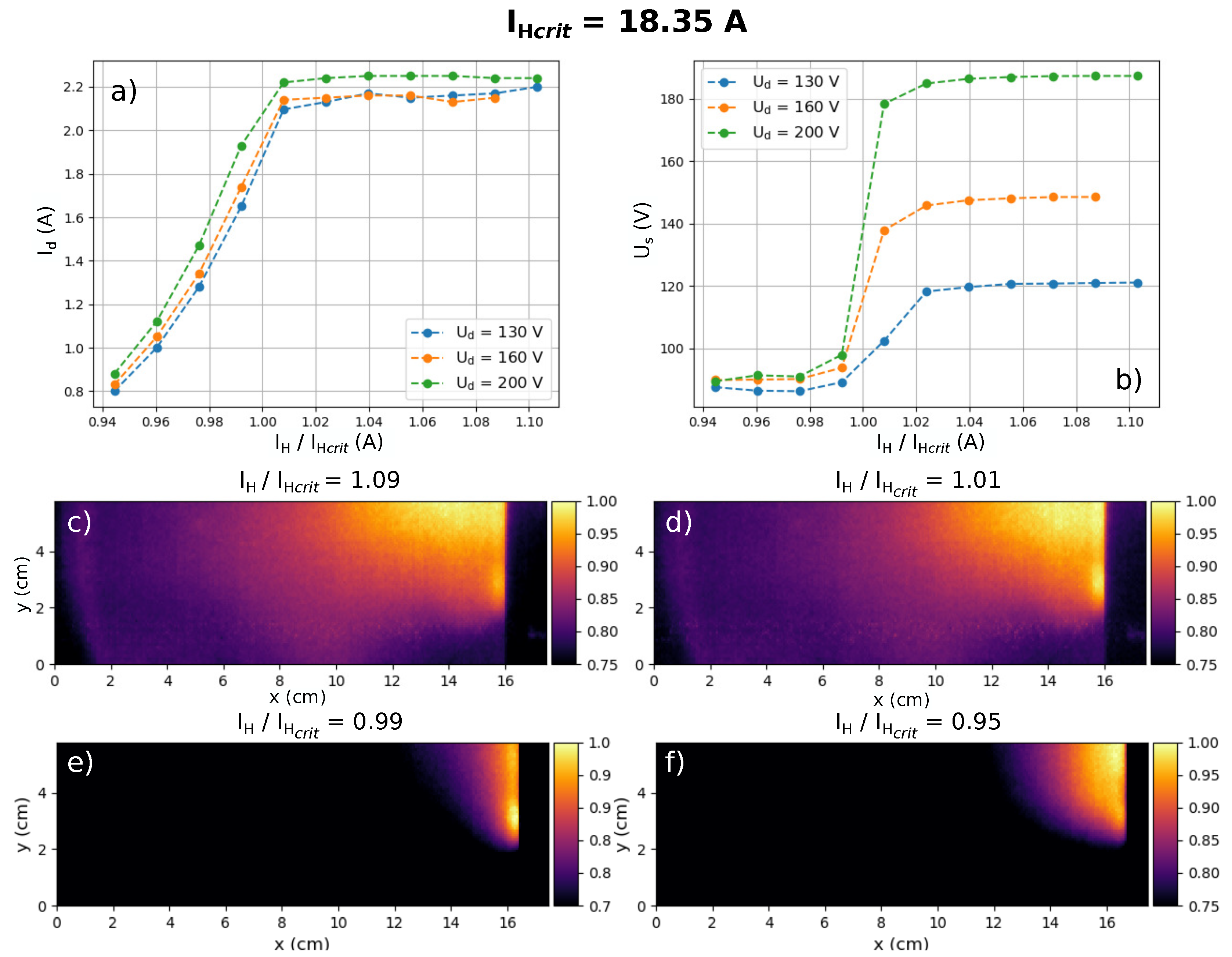
The maximum current emitted by the cathode then strongly varies with the filament temperature. This temperature is easily controllable experimentally by changing the DC heating current I H . In Figure 3a, the HET discharge current averaged over time is plotted against the cathode heating current. I d increases at first with the heating current: the discharge current is limited by the cathode emissivity. I d then reaches a plateau and is no longer limited by the cathode thermionic emission (which keeps increasing with I H ), but by the HET discharge properties. This transition, which happens at a critical heating current I H , c r i t , is associated with a strong modification of the HET plume geometry as shown in Figure 3c–f. On these images, only the bottom 2/3 of the thruster is represented to avoid the cathode brightness disturbing the plume shape. In the case of low heating current and low cathode electron emission ( I H < I H , c r i t ), the HET plume is very small and forms a hemisphere of plasma at the exit of the channel. In the case of higher heating current and higher electron emissivity ( I H > I H , c r i t ), the HET plume is more elongated and pointy and the plasma extends further away from the thruster channel. This second case tends to correspond to typical HET plume and will be called nominal regime, whereas the first case will be called under-emissive regime. Gransted [58] described an effect of the heating current of a filament cathode on the divergence angle of a HET plume but to our knowledge no study currently reports the regime transition described here.
A floating probe was placed in the HET plume to estimate the variation of potential between the anode and the plume U s , or extraction voltage, as displayed in Figure 1b. In an ideal HET, this potential difference U s should be the closest to the imposed discharge voltage U d . In the under-emissive regime (Figure 3b), U s does not depend on the discharge voltage: it remains small and equal to 70 V. When I H crosses the transition limit I H , c r i t , U s quickly increases and gets closer to the discharge voltage.
Both the evolution of the plume shape and the measurement of the extraction voltage suggest that a strong electric field builds up inside the HET channel only if the cathode emissivity is high enough. The critical heating current I H , c r i t defines the limit between two functioning regimes of the HET. To better understand the differences between these two observed discharge regimes, high speed camera measurements of the plasma were made. The results obtained for the nominal and for the under-emissive regime are developed in the next section.

3.2. Analysis of the Oscillatory Phenomenon through the Regime Transition

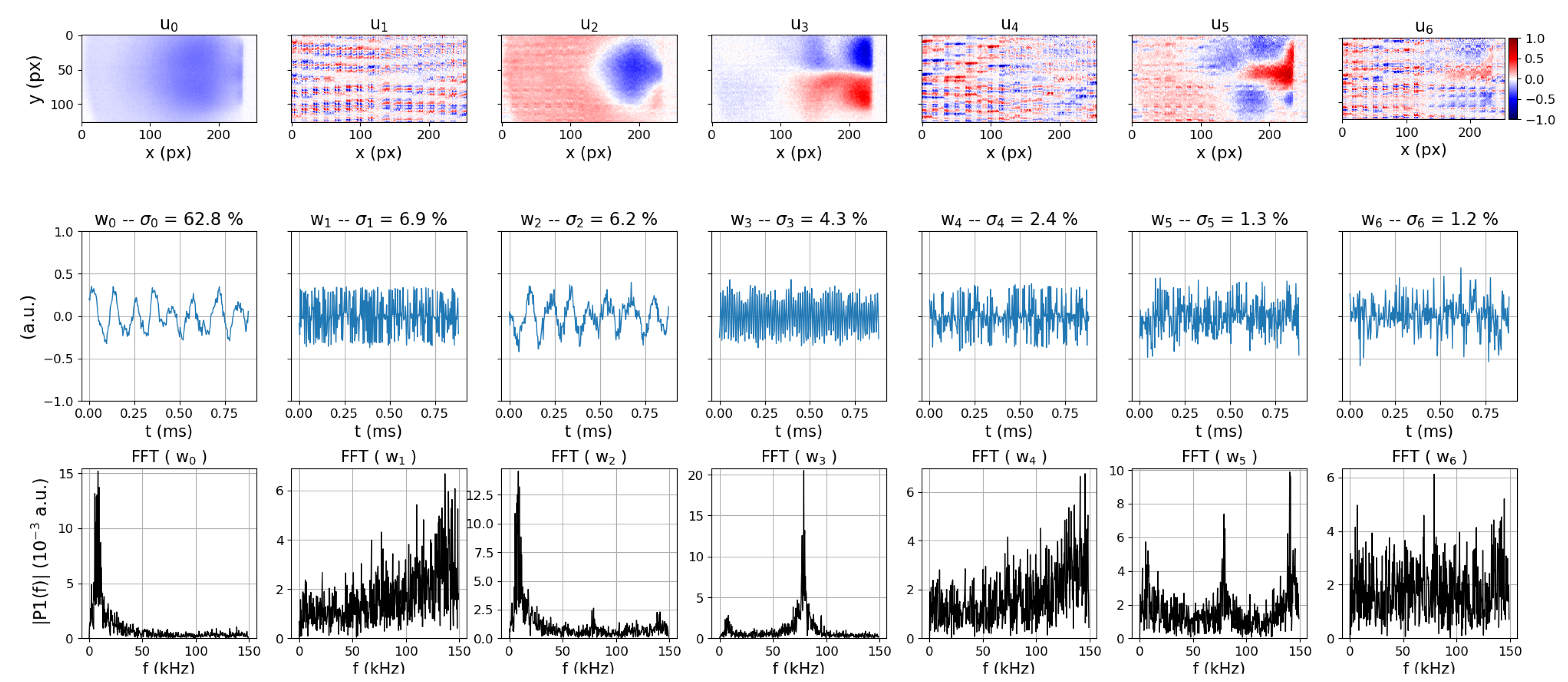
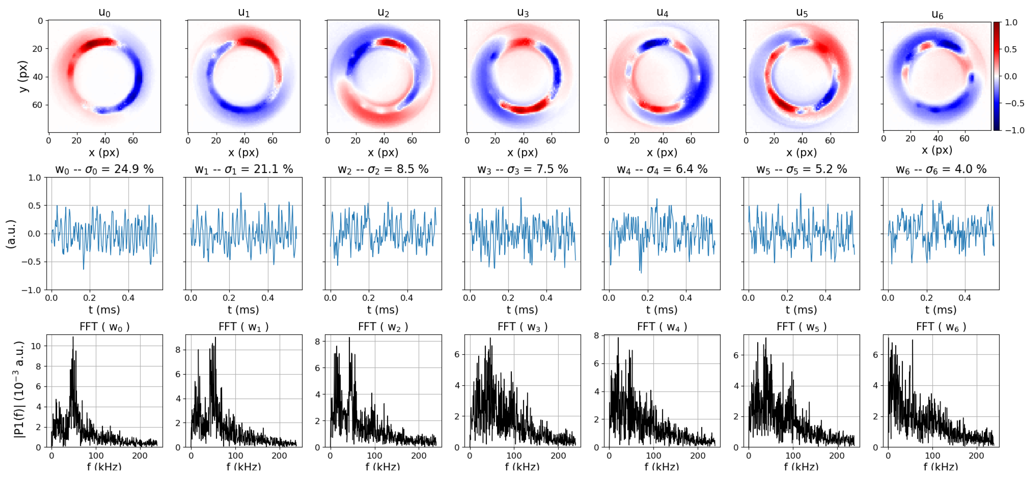
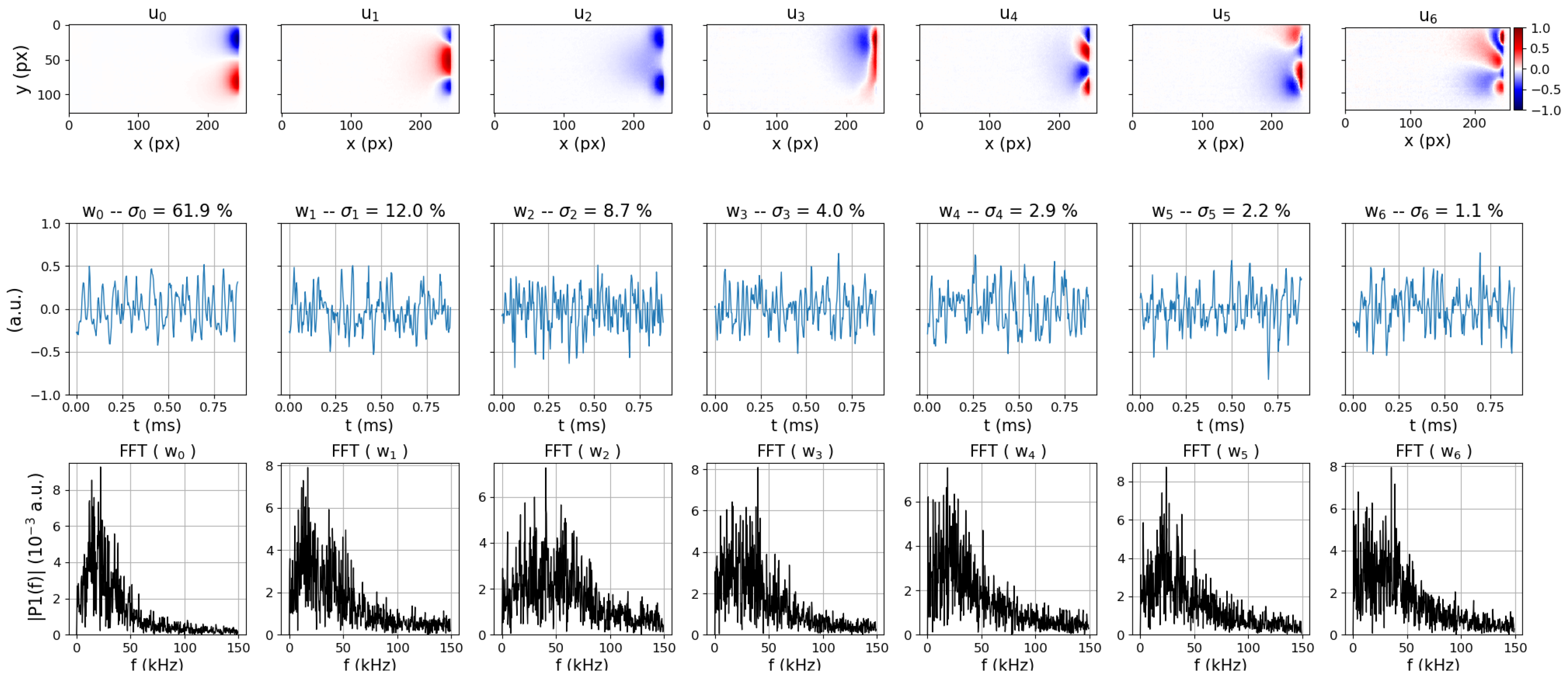
Front and side videos of the thruster have been analysed using the POD method (see Section 2.4). For each video, 800 frames were used to perform the analysis. It represents a time sample of 2.7 ms at a 300 kfps frame rate, 1.7 ms at 480 kfps and 0.9 ms at 900 kfps. The results are displayed as one panel per video, each panel representing all the output parameters of the POD analysis. These panels are all organised the same way. The first row of subplots shows the spatial POD modes u i , i.e., the stationary geometrical description of the POD modes, normalised to one. The second row of subplots presents the first third of the temporal POD modes w i , also normalised to one and representing the instantaneous amplitude of the POD modes. The third row contains the Fast Fourier Transforms (FFT) of the temporal modes w i to give more information on the spectral content of the temporal POD modes. Finally, the singular values λ i of each POD modes are shown in the title of the second row of subplots as σ i equal to λ i 2 over the sum of all the squared singular values and expressed as a percentage. Of the over one hundred POD modes computed, only the ones with the higher σ are displayed, as they represent most of the energy stored in the measured fluctuations. As the POD mode number gets higher, the spatial and temporal content of the POD modes usually get less structured. The POD modes, described by the set { u i , λ i , w i }, are labelled p i . The results of the POD analysis are first presented in the case of the nominal regime before going towards the under-emissive regime and finally, to the transition between these two regimes. This transition is studied for a discharge voltage of 200 V. The results for the nominal regime are shown for both 250 (Figure 4) and 200 V (Figure 5 and Figure 6).

3.2.1. The Nominal Regime

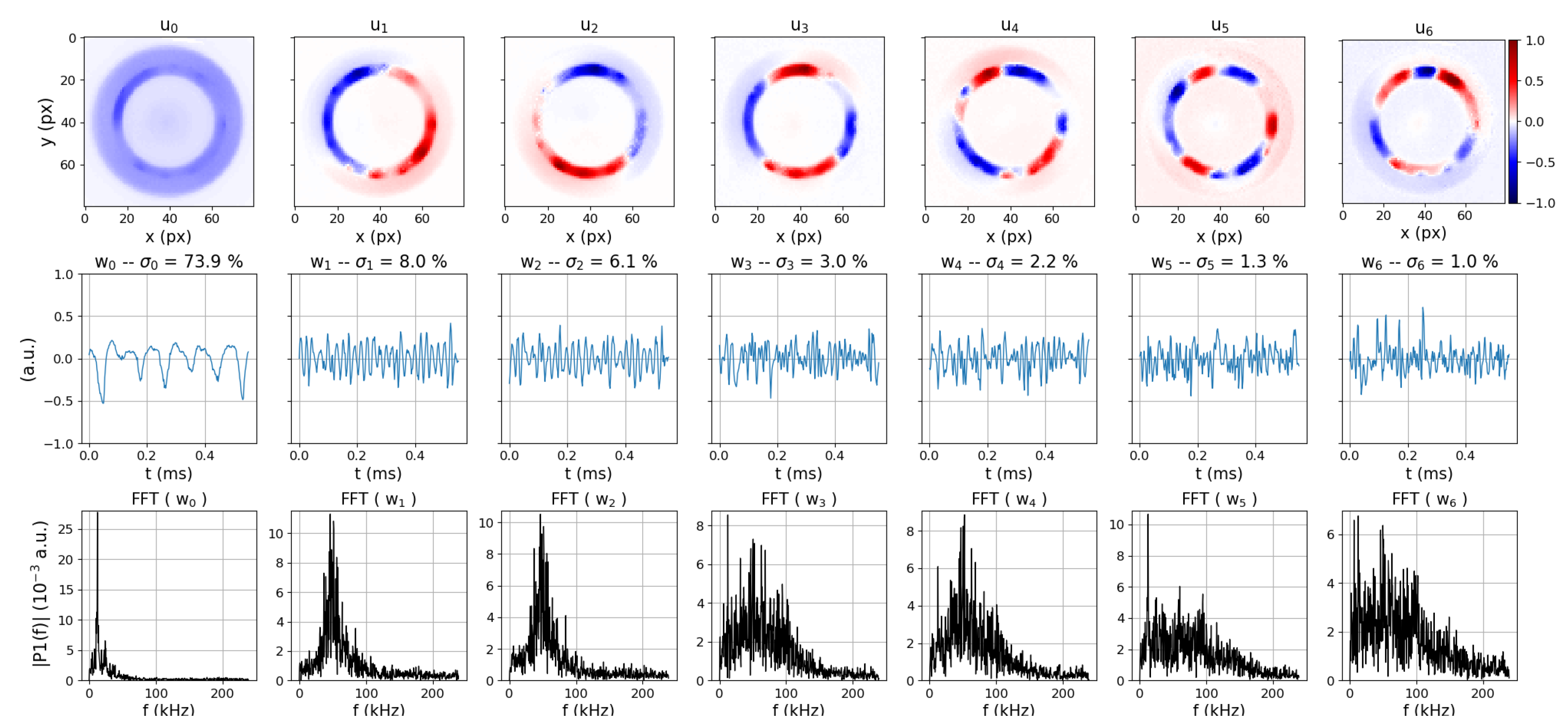
The nominal regime corresponds to a high cathode heating current I H , i.e., to high cathode emissivity. Figure 4 shows the results of the POD analysis conducted on a video acquired in this regime, for a discharge voltage of 250 V and a gas flow of 1.8 mg·s 1 of Xenon. The camera is set on a 480 kfps frame rate and is facing the thruster. The POD modes extracted from this video are the following: an azimuthally homogeneous POD mode p 0 and a series of azimuthally non-homogeneous POD modes from p 1 to p 6 . The first POD mode corresponds to an oscillation of the whole discharge. It has been described extensively in previous studies in larger thrusters [59,60] and is usually called breathing mode. It is described in more details below. The second group of POD modes can be paired by two or three to create rotating objects. For example the POD modes p 1 and p 2 have spatial POD modes that represent an azimuthal fluctuation of the plasma with one maximum and one minimum. This is called an azimuthal mode of order m = 1. u 1 and u 2 see their maximum shifted by 45 and the combination of these two spatial POD modes by temporal signals in phase quadrature allows reconstructing a rotating mode. These rotating modes are described in more details below.

The Breathing Mode

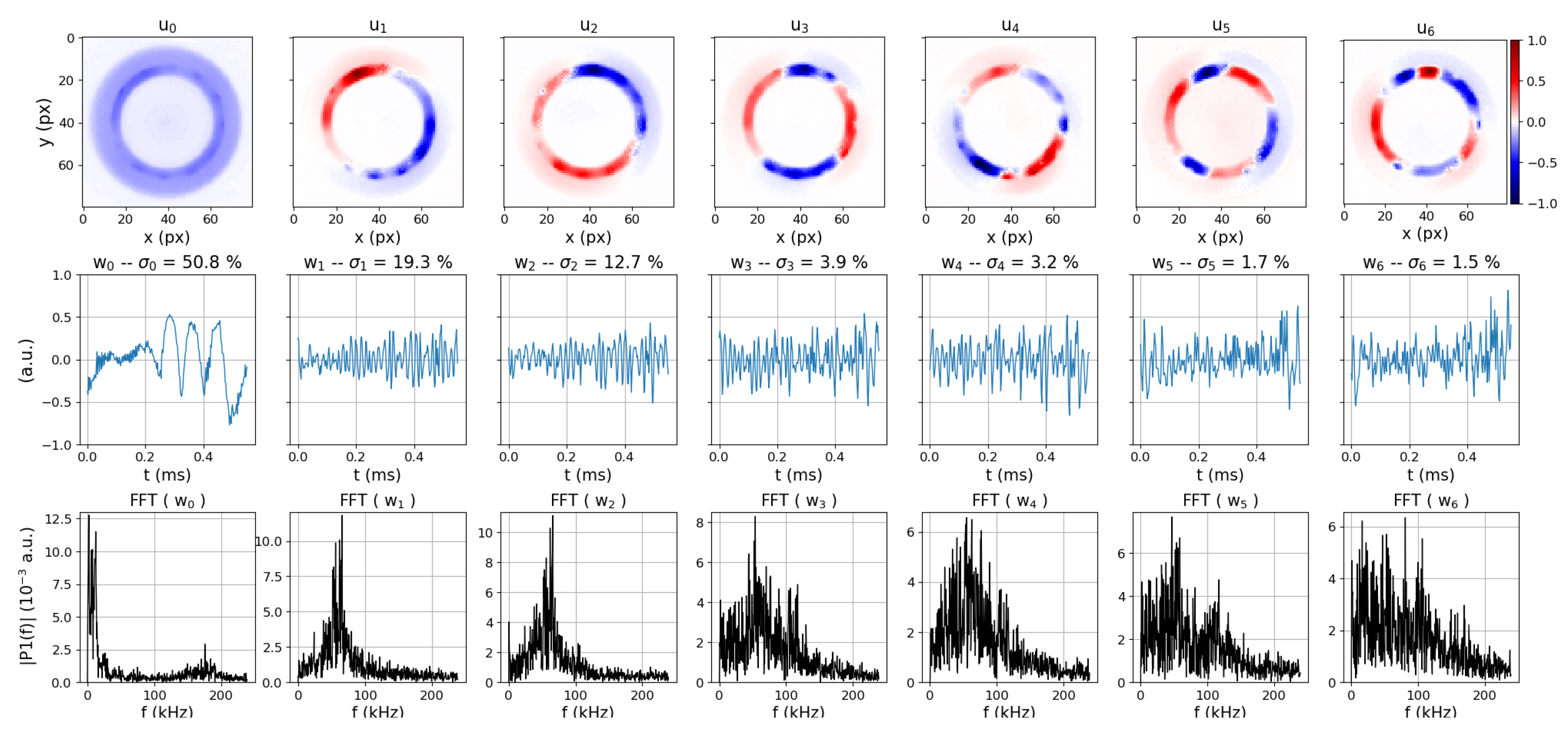
The breathing mode consists of fluctuations of the whole discharge that can be seen easily on the discharge current signal. It usually has a well defined frequency located between 1 and 20 kHz [8]. The mechanism invoked for the generation of this oscillation is a predator–prey model (Lotka–Volterra model) between the neutrals and the ions [33]. First, the discharge channel fills up with neutrals from the anode. Then, these neutrals are strongly ionised in the high magnetic field region which depletes their density profile: the front of neutral density moves towards the anode where the ionisation is less efficient due to a higher electron mobility (lower magnetic field). The discharge current hence decreases, the plasma is extracted by the axial electric field and the ionisation will take place again once the neutral density will be high enough. The cycle will then repeat, with a period depending on the time needed for the atom to replenish the ionisation region. While this simple explanation leads to good order of magnitude for the oscillation frequency [32,33], it has been shown that some assumptions of the model are not valid [19] and hence more theoretical work is needed to better understand these oscillations. The POD mode p 0 of Figure 4 clearly exhibits the characteristics of the breathing mode. It demonstrates an oscillation of the plasma light emission in the whole discharge channel and w 0 oscillates at about 12 kHz. This mode is the dominant mode in the nominal regime, with a σ of 74% in the case of the 250 V discharge and 51% in the case of the 200 V discharge. Whereas it is very regular for a discharge voltage of 250 V, one can notice that the breathing mode is intermittent at 200 V (Figure 5). This intermittency is easily captured by the POD analysis and very explicitly shown on the signal w(t). Further studies on the Breathing Mode frequency, amplitude and intermittency against the experimental parameters will be conducted using these analysis tools. The video reconstruction of this mode can be found in the Supplementary Materials (Video S1).
The analysis of the video taken from the side of the thruster (Figure 6), at 200 V, gives another view of the breathing mode. The breathing mode can be recognised in the POD modes p 0 and p 2 by their azimuthal homogeneity and spectral content. One is axially homogeneous ( u 0 ) and one has a positive and negative axial oscillation ( u 2 ). The generation of a more emissive and then denser plasma region at the exit of the thruster and the ejection of this plasma is constructed by the sum of these two POD modes in phase quadrature. The frequency and the relative amplitude of the breathing mode measured on the front and side videos are very similar. The video reconstruction of this mode can be found in the Supplementary Materials (Video S2)
The POD modes p 1 , p 4 and p 6 in Figure 6 are showing very small patterns that looks like a regular grid. These patterns are homogeneous on the whole frame, even on the right hand side, where no plasma is present (see Figure 2 and Figure 3). This demonstrates that theses POD modes are not associated to the behaviour of the plasma but are showing numerical noise coming from the digitisation of the camera pixel when the movies are acquired. These patterns come out only on the videos from the side because the level of light is too low compared to the camera sensitivity.

The Rotating Modes

Rotating modes have been observed in the past in HETs [36,48] and are starting to be observed in smaller size HETs [30]. Chourei [8] reported two main different types of rotating modes: rotating spokes and gradient induced oscillations. The rotating spokes are typically described by very well defined rotation frequencies ranging from 5 to 25 kHz. They seem to arise from azimuthal ionisation instabilities close to the anode and remain at the back of the thruster channel. To this day, no quantitative theory describing their behaviour has been developed and some advanced numerical simulation work is being led on the subject [34,61]. The gradient induced oscillations originate from the magnetic field and plasma density gradients that give free energy to develop higher frequencies plasma oscillations, ranging from 20 to 60 kHz, with a broader spectral content. These instabilities can be located in the magnetic field and plasma density gradients which are close to the exit of the thruster channel. These instabilities can be compared to instabilities arising in tokamak edge plasmas usually called drift instabilities [62]. Both these types of instabilities are characterised by their phase velocity and their frequency depend on the thruster geometry. The typical figures for the oscillation frequency given by Choueri [8] have been computed for a HET with a 4.5 cm discharge channel mean radius, whereas, in the present study, the mean radius is equal to 2.0 cm. This brings the typically frequency of the rotating spokes to the range 11 to 56 kHz and the typical frequency of the gradient induced oscillations to the range 45 to 135 kHz.
In Figure 4, one can see that after the breathing mode described by the POD mode p 0 , the POD modes from p 1 to p 6 all have local minima and maxima along the azimuthal direction. These modes can be sorted by their number of local minima/maxima, corresponding to the so-called mode number m. Modes of order m = 1 (spatial POD modes u 1 and u 2 ), m = 2 (spatial POD modes u 3 and u 4 ) and m = 3 (spatial POD modes u 5 and u 6 ) are present. One can notice that modes of same mode number also display similar singular values and spectral contents and hence, can be paired. In fact, two POD modes are necessary to described a physical rotating mode. The sum of the two paired spatial POD modes, each multiplied by its temporal POD mode, allow reconstructing an oscillation moving in the azimuthal direction. The paired POD modes quoted above each describe one physical azimuthally rotating plasma oscillation. The rotating mode of order m = 1 has a typical frequency of 58 kHz with a well defined peak. Its σ is about 15 %. The modes m = 2 and m = 3, with lower σ values, 3.5 % and 1.5 %, have very broad frequency peaks covering the spectrum between 5 and 130 kHz. It has been shown in previous experimental work by McDonald et al. [48] on bigger HET that there is a relation between modes of different orders. The high order modes (here m = 2 and m = 3) can be either turbulent smearing of the dominant mode (here m = 1), and, in this case, they have the same oscillation frequency, or harmonics of this lower order dominant mode. It does not seem to be the case here considering the properties of the rotating modes described above. These properties would indicate that the mode m = 1 can be identified as a rotating spoke, whereas the modes m = 2 and m = 3 might be generated by gradient driven instabilities. This would need to be further investigated to confirm these first conclusions. The video of the reconstruction of all these rotating modes are accessible in the Supplementary Materials (Videos S3–S5).
The videos of the plasma taken from the side of the thruster also show rotating modes (Figure 6). The spatial POD mode u 3 is anti-symmetric with respect to the horizontal axis and describes rotating modes escaping from the thruster channel and propagating far in the plume. From this analysis, the mode number cannot be determined. The oscillation frequency of this POD mode is well defined, which seems to link this mode to rotating spokes, but equal to 79 kHz, which is higher than the frequency of the POD mode analysed as a rotating spoke in front video. Moreover, the presence of rotating spokes that far in the thruster plume has not been documented in the literature [34]. The identification of this oscillation as rotating spokes or gradient induced instability is then hazardous.

3.2.2. The under-Emissive Regime

For lower cathode emissivity, the thruster works in an under-emissive regime whose stationary characteristics have been described in Section 3.1. Figure 7 and Figure 8 present the results of the POD analysis of front and side videos of the thruster in this regime. Except from the cathode heating current, which have been lowered from 20.05 to 17.50 A, all the other experimental parameters have been kept fixed. The first observation is that the breathing mode, which was dominating the plasma oscillations in the nominal case, has completely disappeared. The POD output is only composed of rotating modes. In Figure 7, one can see that the rotating modes, which were only located close to the inner wall of the discharge channel in the nominal regime, are now associated with rotating modes in the outer part of the discharge channel. The mode m = 1 is still clearly present with a similar spectral content of 50 kHz. It seems to demonstrate that, unlike the breathing mode, the rotating spokes are not affected by the regime transition. A 15 kHz, frequency oscillation appears on the POD modes p 0 , p 1 and p 2 . It corresponds to a fluctuation of the intensity of the rotating modes, as can be seen in the video S6 in the Supplementary Materials. The nature of this fluctuation is not identified. The spectral content of these fluctuations is very comparable with the spectral content of the POD modes p 0 and p 1 on the side video (Figure 8). These oscillations could be either a faint breathing mode, hidden behind the rotating modes, or a rotating mode with a frequency lower than the previously described ones. Modes of higher order tend to be blurred and are difficult to distinguish.
The POD modes extracted from the side images of the thruster in Figure 8 stay close to the channel exit. This is coherent with the evolution of the plume shape described in Section 3.1 (see Figure 3). The largely dominant mode is the rotating mode p 0 , with a frequency lower than the rotation frequency observed in the front video and comparable to the 15 kHz POD mode (Figure 7). This observation might be showing that the 15-kHz oscillations observed on the front videos are modes rotating outside the thruster channel. More generally, the spatial POD modes exhibit very small structures evolving at very low frequencies, which indicates that the modes are rotating faster inside the thruster channel than in the plume. No mechanism is at this time proposed to explain this type of oscillation at the exit of a HET.

3.2.3. The Transition

Using the results of the POD analysis of the front videos, for six different values of the cathode filament heating current, one can observe the disappearance of the breathing mode (Figure 9). From I H / I H c r i t = 1.09 to I H / I H c r i t = 0.99, the breathing mode sees its relative squared singular value decreasing from 48.5% to 3.6% and goes from the dominant POD mode to the 5th POD mode. Below this heating current, the breathing mode completely disappears.
For cathode emissivity above the critical value or close to it, the thruster discharge oscillations are structured by one or two strong modes that represent at least 30% of the sum of all the singular values. For discharges with lower cathode heating current, the POD mode amplitudes are spread on a larger number of modes with lower amplitude (Figure 9 zoom).

4. Discussion

In the literature, the magnetic field amplitude is usually studied as the main parameter for transitions between HET functioning regime [38,39,40,41]. All these transitions are related to modifications of both the thruster performances and the observed plasma fluctuations. In the case of this study, the observed transition of HET regime is due to a modification of the cathode emissivity. Above the transition, in the nominal regime, the discharge current is independent of the cathode heating current, whereas, below the transition, the discharge current varies continuously with the cathode heating current. The voltage difference between the anode and the plume, referred as extraction voltage, is constant in both regimes but changes abruptly at the transition. It is lower in the under-emissive regime and does not depend on the discharge voltage. In the nominal regime, the extraction voltage is higher and depends on the discharge voltage. This work shows that having a sufficient cathode electron current is needed for the HET to develop a strong potential gradient in its channel.
The use of high-speed camera imaging and video analysis by a POD algorithm allows identifying different oscillation modes in the thruster channel (facing videos) and in the thruster plume (side videos). Two types of modes have been observed: breathing mode and rotating mode.
Whereas the breathing mode is dominating the plasma fluctuations in the nominal regime at high cathode emissivity, it abruptly disappears while transitioning into the under-emissive regime. This loss is most certainly related to the reduction of the electric field inside the thruster channel. It induces a reduction of the ionisation frequency and reduces the neutral depletion and the neutral dynamics role in the drive of the breathing mode. This phenomenon is in good agreement with the loss of the breathing mode at low discharge voltage in previous publication [33]. The physical mechanism responsible for the modification of the extraction voltage at the regime transition is not identify yet and will be the subject of further experimental and numerical investigations.
On the opposite, the rotating modes of order m = 1, which are associated to the previously described rotating spokes, are less sensitive to this transition as they remain present in the under-emissive regime. This is in agreement with the hypothesis linking the spokes formation with an ionisation instability occurring at the back of the discharge channel, even though a small electric field is still necessary to generate the E × B flow at play in this instability. Measurements of the axial electric field from the anode to the plume in both functioning regime will be necessary to confirm these hypothesis. Moreover, we have also observed that, for both regimes, rotating modes can extend far into the thruster plume and can play a role not only in the ionisation region but also in the charge extraction region of the thruster. These rotating modes might be identified as gradient-induced oscillations that usually appear where the magnetic field gradient is negative, or as rotating spokes that have been convected from the near-anode region. This study demonstrates that a lot of these oscillatory phenomena are still largely unexplored. The different instabilities that give birth to these oscillations are not fully understood and experimental work should continue side by side with theoretical and numerical studies in this direction.
Finally, current oscillations are normally detrimental to HETs operation and, to filter them, RLC circuits are used between thrusters and power supplies. Hence, it could be interesting to measure the thruster performances in this under-emissive regime where the main current oscillations (breathing-mode) disappear. However, we should keep in mind that the use of a filament cathode in-space might be challenging but a smaller hollow cathode could also make a thruster work in the under-emissive regime. Moreover, measurements of the different gradients in the plasma would allow for a theoretical stability analysis of the observed instabilities. A deeper analysis of this regime transition and of the reported phenomena will give more insights on the self-organisation of electric field at the exit of HET and improve our knowledge of HET physics.

Supplementary Materials

The following are available online at https://www.mdpi.com/2073-4433/11/5/518/s1, Video S1: Breathing_mode_face_nominal_regime_fps_480kHz_Ud_200V.avi, Video S2: Breathing_mode_side_nominal_regime_fps_300kHz_Ud_200V.avi, Video S3: m-1_face_Nominal_regime_fps_900kHz_Ud_200V.avi, Video S4: m-2_face_Nominal_regime_fps_900kHz_Ud_200V.avi, Video S5: m-3_face_Nominal_regime_fps_900kHz_Ud_200V.avi, Video S6: (u0+u1+u2)_oscillations_face_under-emissive_regime_fps_480kHz_Ud_200V.avi.

Author Contributions

Funding acquisition, A.B. and P.C.; Investigation, V.D., S.S., T.C., N.C., C.D., P.R. and P.C.; Methodology, V.D., P.R. and S.V.; Supervision, V.D., A.B. and P.C.; Writing—original draft, V.D., T.C., N.C. and P.R.; Writing—review & editing, V.D., S.S., T.C., N.C., P.R., S.V., A.B. and P.C. All authors have read and agreed to the published version of the manuscript.

Funding

The authors acknowledge support from the Agence Nationale de la Recherche under the reference ANR-16-CHIN-0003-01 and Safran Aircraft Engines within the project POSEIDON.

Conflicts of Interest

The Co-founder, Safran Aircraft Engines, is part of the research project and had a role in the design of the study. However Safran Aircraft Engines had no role in the collection, analyses, or interpretation of data and in the writing of the manuscript. Safran Aircraft Engines had no role in the decision to publish the results but gave its agreement as confidential information must not be disclosure in this manuscript.

Abbreviations

The following abbreviations are used in this manuscript:
HETHall Effect Thruster
PICParticle-In-Cell
PODProper Orthogonal Decomposition
SVDSingular Value Decomposition

References

  1. Goebel, D.; Katz, I. Fundamentals of Electric Propulsion: Ion and Hall Thrusters; Wiley: Hoboken, NJ, USA, 2008. [Google Scholar]
  2. Lev, D.; Myers, R.M.; Lemmer, K.M.; Kolbeck, J.; Koizumi, H.; Polzin, K. The technological and commercial expansion of electric propulsion. Acta Astronaut. 2019, 159, 213–227. [Google Scholar] [CrossRef]
  3. Adam, J.C.; Boeuf, J.P.; Dubuit, N.; Dudeck, M.; Garrigues, L.; Gresillon, D.; Heron, A.; Hagelaar, G.; Kulaev, V.; Lemoine, N.; et al. Physics, simulation and diagnostics of Hall effect thrusters. Plasma Phys. Control. Fusion 2008, 50, 124041. [Google Scholar] [CrossRef]
  4. Mazouffre, S. Electric propulsion for satellites and spacecraft: Established technologies and novel approaches. Plasma Sources Sci. Technol. 2016, 25, 033002. [Google Scholar] [CrossRef]
  5. Boeuf, J.P. Tutorial: Physics and modeling of Hall thrusters. J. Appl. Phys. 2017, 121, 011101. [Google Scholar] [CrossRef]
  6. Morozov, A.I.; Savelyev, V. Fundamentals of Stationary Plasma Thruster Theory. Rev. Plasma Phys. 2000, 21, 203–391. [Google Scholar]
  7. Morozov, A.I. The conceptual development of stationary plasma thrusters. Plasma Phys. Rep. 2003, 29, 235–250. [Google Scholar] [CrossRef]
  8. Choueiri, E. Plasma oscillations in Hall thrusters. Phys. Plasmas 2001, 8, 1411. [Google Scholar] [CrossRef] [Green Version]
  9. Smolyakov, A.; Chapurin, O.; Frias Pombo, W.; Koshkarov, O.; Romadanov, I.; Tang, T.; Umansky, M.; Raitses, Y.; Kaganovich, I.; Lakhin, V. Fluid theory and simulations of instabilities, turbulent transport and coherent structures in partially-magnetized plasmas of E × B discharges. Plasma Phys. Control Fusion 2017, 59, 014041. [Google Scholar] [CrossRef]
  10. Chesta, E.; Lam, C.M.; Meezan, N.B.; Schmidt, D.P.; Cappelli, M.A. A characterization of plasma fluctuations within a Hall discharge. IEEE Trans. Plasma Sci. 2001, 29, 582–591. [Google Scholar] [CrossRef]
  11. Litvak, A.A.; Raitses, Y.; Fisch, N.J. Experimental studies of high-frequency azimuthal waves in Hall thrusters. Phys. Plasmas 2004, 11, 1701–1705. [Google Scholar] [CrossRef]
  12. Tsikata, S.; Lemoine, N.; Pisarev, V.; Grésillon, D.M. Dispersion relations of electron density fluctuations in a Hall thruster plasma, observed by collective light scattering. Phys. Plasmas 2009, 16, 033506. [Google Scholar] [CrossRef]
  13. Lobbia, R.B. A Time-resolved Investigation of the Hall Thruster Breathing Mode. Ph.D. Thesis, The University of Michigan, Ann Arbor, MI, USA, 2010. [Google Scholar]
  14. Brown, Z.A.; Jorns, B.A. Spatial evolution of small wavelength fluctuations in a Hall Thruster. Phys. Plasmas 2019, 26, 113504. [Google Scholar] [CrossRef]
  15. Fife, J.M. Hybrid-PIC Modeling and Electrostatic Probe Survey of Hall Thrusters. Ph.D. Thesis, Massachussets Instititute of Technology, Cambridge, MA, USA, 1998. [Google Scholar]
  16. Lafleur, T.; Chabert, P. The role of instability-enhanced friction on ‘anomalous’ electron and ion transport in Hall-effect thrusters. Plasma Sources Sci. Technol. 2018, 27, 015003. [Google Scholar] [CrossRef]
  17. Hara, K. An overview of discharge plasma modeling for Hall effect thrusters. Plasma Sources Sci. Technol. 2019, 28, 044001. [Google Scholar] [CrossRef]
  18. Cavalier, J.; Lemoine, N.; Bonhomme, G.; Tsikata, S.; Honore, C.; Gresillon, D. Hall thruster plasma fluctuations identified as the E × B electron drift instability: Modeling and fitting on experimental data. Phys. Plasmas 2013, 20, 082107. [Google Scholar] [CrossRef]
  19. Hara, K.; Sekerak, M.J.; Boyd, I.D.; Gallimore, A.D. Perturbation analysis of ionization oscillations in Hall effect thrusters. Phys. Plasmas 2014, 21, 122103. [Google Scholar] [CrossRef]
  20. Lafleur, T.; Baalrud, S.D.; Chabert, P. Theory for the anomalous electron transport in Hall effect thrusters. II. Kinetic model. Phys. Plasmas 2016, 23, 053503. [Google Scholar] [CrossRef] [Green Version]
  21. Joncquieres, V. Modélisation et simulation numérique des moteurs à effet Hall. Ph.D. Thesis, Institut National Polytechnique de Toulouse, Toulouse, France, 2019. [Google Scholar]
  22. Mikellides, I.G.; Jorns, B.; Katz, I.; Lopez Ortega, A. Hall2De Simulations with a First-principles Electron Transport Model Based on the Electron Cyclotron Drift Instability. In Proceedings of the 52nd AIAA/SAE/ASEE Joint Propulsion Conference. American Institute of Aeronautics and Astronautics, Salt Lake City, UT, USA, 25–27 July 2016. [Google Scholar]
  23. Martorelli, R.; Lafleur, T.; Bourdon, A.; Chabert, P. Comparison between ad-hoc and instability-induced electron anomalous transport in a 1D fluid simulation of Hall-effect thruster. Phys. Plasmas 2019, 26, 083502. [Google Scholar] [CrossRef]
  24. Katz, I.; Ortega, A.L.; Jorns, B.; Mikellides, I. Growth and Saturation of Ion Acoustic Waves in Hall Thrusters. In Proceedings of the 52nd AIAA/SAE/ASEE Joint Propulsion Conference, Salt Lake City, UT, USA, 25–27 July 2016. [Google Scholar]
  25. Croes, V. Modélisation bidimensionnelle de la décharge plasma dans un propulseur de Hall. Ph.D. Thesis, Université Paris-Saclay, Saint-Aubin, France, 2018. [Google Scholar]
  26. Tavant, A. Plasma-Wall Interaction and Electron Transport in Hall Effect Thrusters. Ph.D. Thesis, Université Paris-Saclay, Saint-Aubin, France, 2019. [Google Scholar]
  27. Charoy, T.; Boeuf, J.P.; Bourdon, A.; Carlsson, J.A.; Chabert, P.; Cuenot, B.; Eremin, D.; Garrigues, L.; Hara, K.; Kaganovich, I.D.; et al. 2D axial-azimuthal particle-in-cell benchmark for low-temperature partially magnetized plasmas. Plasma Sources Sci. Technol. 2019, 28, 105010. [Google Scholar] [CrossRef] [Green Version]
  28. Mikellides, I.G.; Ortega, A.L. Challenges in the development and verification of first-principles models in Hall-effect thruster simulations that are based on anomalous resistivity and generalized Ohm’s law. Plasma Sources Sci. Technol. 2019, 28, 014003. [Google Scholar] [CrossRef]
  29. Tichý, M.; Pétin, A.; Kudrna, P.; Horký, M.; Mazouffre, S. Electron energy distribution function in a low-power Hall thruster discharge and near-field plume. Phys. Plasmas 2018, 25, 061205. [Google Scholar] [CrossRef]
  30. Mazouffre, S.; Grimaud, L.; Tsikata, S.; Matyash, K.; Schneider, R. Rotating spoke instabilities in a wall-less Hall thruster: Experiments. Plasma Sources Sci. Technol. 2019, 28, 054002. [Google Scholar] [CrossRef]
  31. Holmes, P.; Lumley, J.; Berkooz, G.; Rowley, C. Turbulence, Coherent Structures, Dynamical Systems and Symmetry, 2nd ed.; Cambridge Monographs on Mechanics; Cambridge University Press: Cambridge, UK, 2012. [Google Scholar]
  32. Boeuf, J.P.; Garrigues, L. Low frequency oscillations in a stationary plasma thruster. J. Appl. Phys. 1998, 84, 3541–3554. [Google Scholar] [CrossRef]
  33. Barral, S.; Ahedo, E. Low-frequency model of breathing oscillations in Hall discharges. Phys. Rev. E 2009, 79, 046401. [Google Scholar] [CrossRef] [Green Version]
  34. Kawashima, R.; Hara, K.; Komurasaki, K. Numerical analysis of azimuthal rotating spokes in a crossed-field discharge plasma. Plasma Sources Sci. Technol. 2017, 27, 035010. [Google Scholar] [CrossRef] [Green Version]
  35. Rodríguez, E.; Skoutnev, V.; Raitses, Y.; Powis, A.; Kaganovich, I.; Smolyakov, A. Boundary-induced effect on the spoke-like activity in E × B plasma. Phys. Plasmas 2019, 26, 053503. [Google Scholar] [CrossRef] [Green Version]
  36. Janes, G.S.; Lowder, R.S. Anomalous Electron Diffusion and Ion Acceleration in a Low Density Plasma. Phys. Fluids 1966, 9, 1115. [Google Scholar] [CrossRef]
  37. Morozov, A.I.; Epsinchuc, Y.; Kapulkin, A.M. Effect of the magnetic field a closed-electron-drift accelerator. Sov. Phys. Tech. Phys. 1972, 17, 482. [Google Scholar]
  38. Tilinin, G.N. High-frequency plasma waves in a Hall accelerator with an extended acceleration zone. Sov. Phys. Tech. Phys. 1977, 22, 974. [Google Scholar]
  39. Hara, K.; Sekerak, M.; Boyd, I.; Gallimore, A. Mode transition of a Hall thruster discharge plasma. J. Appl. Phys. 2014, 115, 203304. [Google Scholar] [CrossRef]
  40. Sekerak, M.; Gallimore, A.D.; Brown, D.L.; Hofer, R.; Polk, J. Mode Tansitions in Hall-Effect Thrusters Induced by Variable Magnetic Field Strength. J. Propuls. Power 2016, 32, 903–917. [Google Scholar] [CrossRef] [Green Version]
  41. Khmelevskoi, I.; Lovtsov, A.; Tomilin, D. Study of two Different Discharge Modes in Hall Thruster. In Proceedings of the 36th International Electric Propulsion Conference, Vienna, Austria, 15–20 September 2019; p. 387. [Google Scholar]
  42. Klinger, T.; Latten, A.; Piel, A.; Bonhomme, G.; Pierre, T. Chaos and turbulence studies in low-β plasmas. Plasma Phys. Control Fusion 1997, 39, B145–B156. [Google Scholar] [CrossRef]
  43. Brandt, C.; Grulke, O.; Klinger, T.; Negrete, J.; Bousselin, G.; Brochard, F.; Bonhomme, G.; Oldenbürger, S. Spatiotemporal mode structure of nonlinearly coupled drift wave modes. Phys. Rev. E 2011, 84, 056405. [Google Scholar] [CrossRef] [PubMed]
  44. Thakur, S.C.; Brandt, C.; Cui, L.; Gosselin, J.J.; Light, A.D.; Tynan, G.R. Multi-instability plasma dynamics during the route to fully developed turbulence in a helicon plasma. Plasma Sources Sci. Technol. 2014, 23, 0440006. [Google Scholar] [CrossRef]
  45. Lucken, R.; Bourdon, A.; Lieberman, M.A.; Chabert, P. Instability-enhanced transport in low temperature magnetized plasma. Phys. Plasmas 2019, 26, 070702. [Google Scholar] [CrossRef] [Green Version]
  46. Karabadzhak, G.F.; Chiu, Y.H.; Dressler, R.A. Passive optical diagnostic of Xe propelled Hall thrusters. II. Collisional-radiative model. J. Appl. Phys. 2006, 99, 113304. [Google Scholar] [CrossRef] [Green Version]
  47. Mazouffre, S.; Tsikata, S.; Vaudolon, J. Development and experimental characterization of a wall-less Hall thruster. J. Appl. Phys. 2014, 116, 243302. [Google Scholar] [CrossRef]
  48. McDonald, M.S.; Gallimore, A.D. Parametric Investigation of the Rotating Spoke Instability in Hall Thrusters. In Proceedings of the 32nd International Electric Propulsion Conference, Weisbaden, Germany, 11–15 September 2011; p. 242. [Google Scholar]
  49. Diamant, K.; Liang, R.; Corey, R. The Effect of Background Pressure on SPT-100 Hall Thruster Performance. ARC 2014. [Google Scholar] [CrossRef]
  50. Oldenbürger, S.; Brandt, C.; Brochard, F.; Lemoine, N.; Bonhomme, G. Spectroscopic interpretation and velocimetry analysis of fluctuations in a cylindrical plasma recorded by a fast camera. Rev. Sci. Instrum. 2010, 81, 063505. [Google Scholar] [CrossRef]
  51. Zweben, S.J.; Terry, J.L.; Stotler, D.P.; Maqueda, R.J. Invited Review Article: Gas puff imaging diagnostics of edge plasma turbulence in magnetic fusion devices. Rev. Sci. Instrum. 2017, 88, 041101. [Google Scholar] [CrossRef] [Green Version]
  52. Pearson, K. On lines and planes of closest fit to systems of points in space. Lond. Edinb. Dublin Philos. Mag. J. Sci. 1901, 2, 559–572. [Google Scholar] [CrossRef] [Green Version]
  53. Kosambi, D. Statistics in function space. J. Ind. Math. Soc. 1943. [Google Scholar] [CrossRef]
  54. Lumley, J.L. The structure of inhomogeneous turbulence. In Atmospheric Turbulence and Wave Propagation; Yaglom, A.M., Tatarski, V.I., Eds.; Nauka: Moscow, Russia, 1967; pp. 166–178. [Google Scholar]
  55. Sirovich, L. Turbulence and the Dynamics of Coherent Structures, Part I: Coherent Structures. Q. Appl. Math. 1987, 45, 561–571. [Google Scholar] [CrossRef] [Green Version]
  56. Demmel, J. Singular Value Decomposition. In Templates for the Solution of Algebraic Eigenvalue Problems; Software; Environments and Tools, Society for Industrial and Applied Mathematics: Philadelphia, PA, USA, 2000; pp. 135–147. [Google Scholar] [CrossRef] [Green Version]
  57. Richardson, O.W. Electron Emission from Metals as a Function of Temperature. Phys. Rev. 1924, 23, 153. [Google Scholar] [CrossRef]
  58. Granstedt, E.M.; Raitses, Y.; Fisch, N.J. Cathode effects in cylindrical Hall thrusters. J. Appl. Phys. 2008, 104, 103302. [Google Scholar] [CrossRef] [Green Version]
  59. Darnon, F.; Garrigues, L.; Boeuf, J.P.; Bouchoule, A.; Lyszyk, M. Spontaneous Oscillations in a Hall Thruster. IEEE Trans. Plasm Sci. 1999, 27, 98–99. [Google Scholar] [CrossRef]
  60. Bouchoule, A.; Philippe-Kadlec, C.; Prioul, M.; Darnon, F.; Lyszyk, M.; Magne, L.; Pagon, D.; Roche, S.; Touzeau, M.; Béchu, S.; et al. Transient phenomena in closed electron drift plasma thrusters: Insights obtained in a French cooperative program. Plasma Sources Sci. Technol. 2001, 10, 364. [Google Scholar] [CrossRef]
  61. Matyash, K.; Schneider, R.; Mazouffre, S.; Tsikata, S.; Grimaud, L. Rotating spoke instabilities in a wall-less Hall thruster: Simulations. Plasma Sources Sci. Technol. 2019, 28, 044002. [Google Scholar] [CrossRef] [Green Version]
  62. Horton, W. Drift waves and transport. Rev. Mod. Phys. 1999, 71, 735. [Google Scholar] [CrossRef] [Green Version]
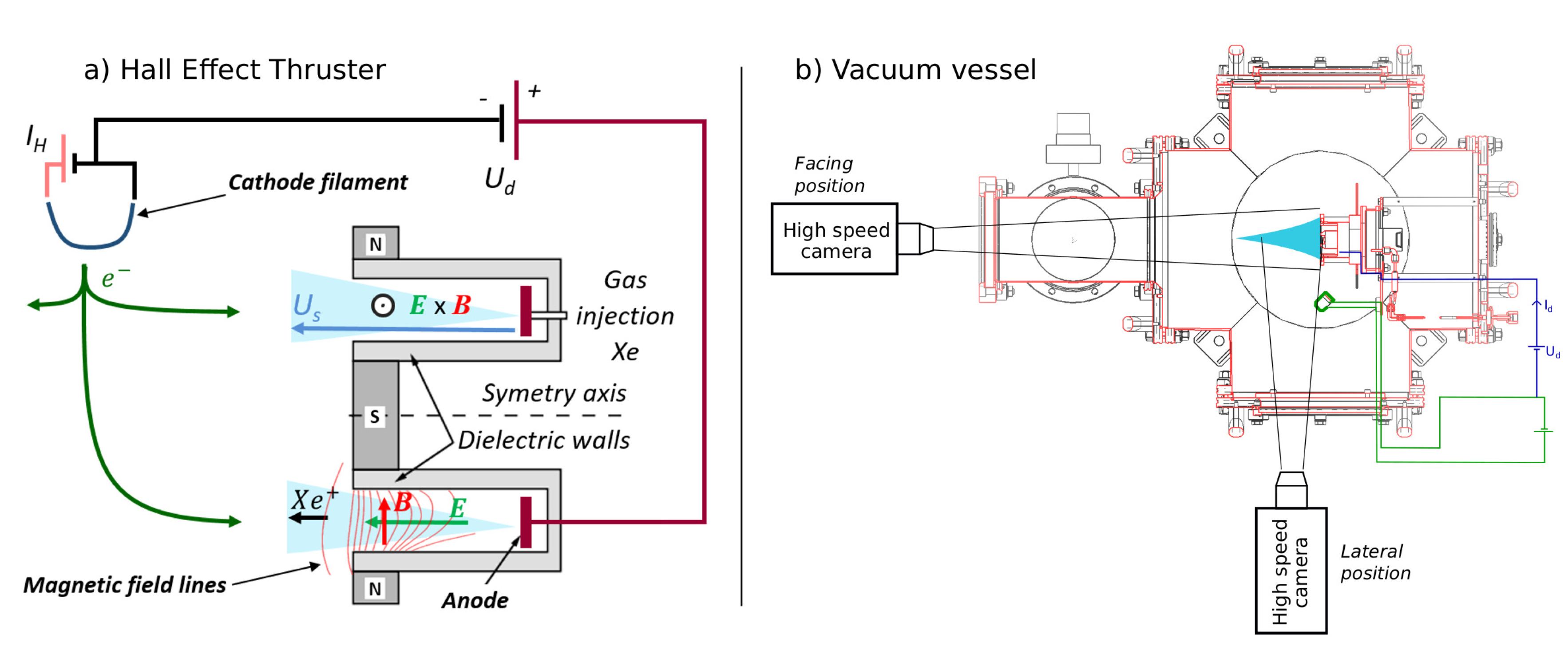
Figure 1. Schematics of: (a) a HET side view, with relevant parameters: discharge voltage U d , discharge current I d , cathode heating current I H and potential difference between the anode and the plume U S ; and (b) an experimental vacuum chamber with the two camera positions.
Atmosphere 11 00518 g001
Figure 2. Example of images captured with the high-speed camera in front of the thruster (top row) and from the side (bottom row). For both cases, the discharge parameters are: I H = 20.05 Amps ( I H / I H , c r i t = 1.09), Q = 1.8 mg·s 1 and U d = 200 V. (Left) Raw image; (Middle) mean image over the whole acquisition time interval; and (Right) raw image minus the mean image. The light intensity is given in counts, encoded between 0 and 4096 for the raw images and the mean images and between −4096 and +4096 for the raw images minus the mean images.
Atmosphere 11 00518 g002
Figure 3. (a) Evolution of the HET discharge current I d depending on the cathode heating current I H for different discharge voltage U d . The heating current is normalised to the heating current at the regime transition I H , c r i t . (b) Evolution of the potential difference between anode and plume U s depending on the normalised cathode heating current for different discharge voltage U d . (cf) The side view of the plume for different values of normalised cathode heating current. The other discharge parameters are Q = 1.8 mg·s 1 and U d = 200 V. The light intensity has been normalised to each image maximum.
Atmosphere 11 00518 g003
Figure 4. Nominal regime: POD analysis of the front videos with a discharge voltage U d = 250 V, a mass flow rate Q = 1.8 mg·s 1 , a cathode heating current I H = 19.95 A ( I H / I H , c r i t = 1.08) and a acquisition frequency of F f p s = 480 kfps. (Top) Spatial POD modes u i ; (Middle) corresponding temporal POD modes w i with their singular value λ i given as σ i = λ i 2 over the sum of all the λ i expressed as a percentage; and (Bottom) corresponding FFT.
Atmosphere 11 00518 g004
Figure 5. Nominal regime: POD analysis of the front videos with a discharge voltage U d = 200 V, a mass flow rate Q = 1.8 mg·s 1 , a cathode heating current I H = 20.05 A ( I H / I H , c r i t = 1.09) and a acquisition frequency of F f p s = 480 kfps. (Top) Spatial POD modes u i ; (Middle) corresponding temporal POD modes w i with their singular value λ i given as σ i = λ i 2 over the sum of all the λ i expressed as a percentage; and (Bottom) corresponding FFT.
Atmosphere 11 00518 g005
Figure 6. Nominal regime: POD analysis of the side videos with a discharge voltage U d = 200 V, a mass flow rate Q = 1.8 mg·s 1 , a cathode current I H = 20.05 A ( I H / I H , c r i t = 1.09) and a acquisition frequency of F f p s = 300 kfps. (Top) Spatial POD modes u i ; (Middle) corresponding temporal POD modes w i with their singular value λ i given as σ i = λ i 2 over the sum of all the λ i expressed as a percentage; and (Bottom) corresponding FFT.
Atmosphere 11 00518 g006
Figure 7. Under-emissive regime: POD analysis of the front videos with a discharge voltage U d = 200 V, a mass flow rate Q = 1.8 mg·s 1 , a cathode heating current I H = 17.50 A ( I H / I H , c r i t = 0.95) and a acquisition frequency of F f p s = 480 kfps. (Top) Spatial POD modes u i ; (Middle) corresponding temporal POD modes w i with their singular value λ i given as σ i = λ i 2 over the sum of all the λ i expressed as a percentage; and (Bottom) corresponding FFT.
Atmosphere 11 00518 g007
Figure 8. Under-emissive regime: POD analysis of the side videos with a discharge voltage U d = 200 V, a mass flow rate Q = 1.8 mg·s 1 , a cathode heating current I H = 17.50 A ( I H / I H , c r i t = 0.95) and a acquisition frequency of F f p s = 300 kfps. (Top) Spatial POD modes u i ; (Middle) corresponding temporal POD modes w i with their singular value λ i given as σ i = λ i 2 over the sum of all the λ i expressed as a percentage; and (Bottom) corresponding FFT.
Atmosphere 11 00518 g008
Figure 9. Evolution of the relative singular values λ i given as σ i = λ i 2 over the sum of all the λ i 2 expressed as a percentage for the 14th first POD modes and for different values of the heating current ratio I H / I H , c r i t . For each value of I H / I H , c r i t , the mode corresponding to the breathing mode is represented with a filled symbol.
Atmosphere 11 00518 g009