Abstract
Tunnels located in cold regions are vulnerable to frost damage resulting from the special atmosphere, which directly threatens the safety of the tunnel structure and operation. Frost problems of tunnels in cold regions have not been fundamentally resolved. This paper reviews design theory and the frost mitigation techniques currently used in the design, construction and maintenance of cold region tunnels. The depths of freezing and thawing and frost heaving force are the key indexes of design theory. Insulation is the main design technology used to prevent frost heaving and thawing, and the active heating technology has also been applied in practice. In construction, reducing the heat of hydration and blasting by specific winter construction techniques can prevent tunnel freeze–thaw damages. In operation, the restoration of drainage systems, the reinforcement of structures and the reinstallation of freezing-prevention systems are effective measures to treat frost problems. Finally, some constructive suggestions and opinions are put forward to improve the service performance of tunnels.
1. Introduction
In China, 52.4% of 15,117 tunnels have suffered frost damage [1,2], and in Japan 38.2% of tunnels have suffered frost problems [3]. Tunnels in Gangwon province of South Korea are also affected by a number of frost problems [4]. Based on the maximum freezing depth and the monthly average temperature in January, the tunnel frost damage intensity can be divided into several levels in the seasonal freezing areas of the Northern Hemisphere. In a survey of 156 tunnels in China, Gao et al. [5] divided tunnels in cold regions into high-latitude tunnels and high-altitude tunnels. Frost problems include lining material deterioration, tunnel deformation and cracking, concrete spalling, seepage and icing [6,7,8,9,10,11,12]. Tunnel linings can deform and crack under frost heaving and are intensified by forced ventilation and inadequate drainage. In addition, when the thermal stress acting on the lining is greater than the tensile strength of the lining, many cracks are formed [8,10]. As a result, the lining cracking causes more leakage in a tunnel than usual. Icing occurs when the temperature inside a tunnel is below zero, which affects the structure and traffic safety of the tunnel. Tunnels need more security systems and equipment to better withstand cold weather and reduce casualties and prolonged disruptions to the transport system [13]. Although there are many related studies, many challenges related to frost problems remain in theory and practice [14,15,16]. In permafrost regions, the basic principles of design and construction are to protect the tunnel-surrounding rock and the tunnel entrance slope from warming and thawing [17].
More and more tunnels are being constructed in cold regions, with difficulties in construction and maintenance in practice. Firstly, a large number of references about cold region tunnels are collected and read. Secondly, these related and important references are classified into four collections based on design theory, techniques for frost problem mitigation in design, construction and maintenance. And then, past and present techniques of frost-problem mitigation in the design, construction and maintenance of cold-regional tunnels (Figure 1) are summarized. Finally, some new ideas and directions to solve these problems are put forwards.
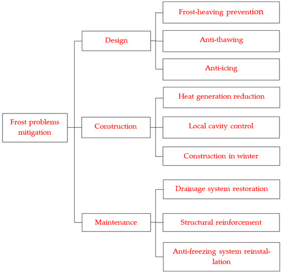
Figure 1.
Frost-problem mitigation techniques.
2. Theory of Tunnel Design in Cold Regions
2.1. Freezing and Thawing Depth
The depth of the freezing and thawing of the surrounding rock affects the thermal stability of cold-region tunnels. Engineers and researchers are thus interested in the temperature of the surrounding rock. The thermal conductivity of the surrounding rock is one of the most important factors affecting the temperature distribution. The thermal conductivity is usually obtained in laboratory tests or using empirical formulas [18,19] (Table 1).

Table 1.
Thermal conductivity models.
The depths of the freezing and thawing of the surrounding rock are easily determined if the temperature distribution of the surrounding rock is obtained. It is thus important to obtain the temperature distribution of the surrounding rock. The underground temperature field is affected by the ventilation, groundwater, and thickness of the secondary lining; i.e., the temperature distribution around a tunnel is affected by seepage, moisture transfer, the phase change, and air flow. It is therefore difficult to obtain the temperature distribution of the surrounding rock and tunnel structure. However, there are approximate analytical formulas and many numerical solutions.
The analytical solution of the temperature distribution is difficult to obtain and is approximate. There are only a few solutions of the solutions which are based on differential equations of heat transfer. First lining, insulation, second lining, and surrounding rock including frozen or unfrozen zone are assumed to be different materials. However, the approximate analytical solutions have been obtained by different methods, such as the dimensionless and perturbative method [22], orthogonal and expansion theorem of the Bessel eigenfunction [23], superposition principle and the orthogonal expansion of the Bessel eigenfunction [24], Stehfest numerical inversion method [25], quasi-steady state assumption and integration [26], and so on.
Solving the temperature-distribution solution of a tunnel in a cold region is a complex problem that should include the heat transfer, coupling of the heat transfer and seepage, coupling of the heat transfer and heat convection between the air in the tunnel and surrounding rock, and the ice-water phase change (Table 2). Lai derived governing differential equations of the coupled problem of temperature and seepage fields with a phase change from the theory of heat transfer and seepage [27,28]. Zhang and Zhang obtained the finite element formulae of three-dimensional temperature fields with a phase change using Galerkin’s method based on the governing differential equations of the temperature field [29,30]. Lai presented a three-dimensional calculation model of the coupled problem according to the basic theories of heat transfer, geocryology, and fluid mechanics, taking the coupled problem of the heat transfer of the surrounding rock and the heat convection between the air in the tunnel and the surrounding rock into account [31]. Yang introduced a common numerical method of solving the moisture and heat coupling for the soft rock of tunnels in cold regions [32]. Zhang developed a program including the latent heat of a change in phase based on the finite difference method and internal FISH language of FLAC3D2.1 [33]. Tan established governing equations for a thermohydro coupling model according to the basic law of water flow and heat transfer in porous media under freeze/thaw conditions, adopting the theory of continuum mechanics, thermodynamics, and the segregation potential [34]. Tan obtained the temperature field distribution with an ice-water phase change occurring in porous media by adjusting the parameters of the unfrozen water contents of the frozen zone, freezing zone, and unfrozen zone [35]. Tan presented an adaptive finite element method based on a standard k-ε turbulence model, wall function, and thermal function [36]. Tan developed a temperature field model that includes temperature control equations of the surrounding rock, air temperature field control equations of the tunnel, and wind flow control equations of the turbulence field [37]. Zhou developed an unsteady-state finite-difference numerical model to study heat convection between the air and the tunnel wall and the heat transfer in the surrounding rock and at interfaces between different materials in the structure of the tunnel according to unsteady-state finite-difference equations for heat transfer and heat convection [38]. Jin developed a heating element to study the temperature of groundwater at the backfill of the tunnel lining [39].
Table 2.
Differential equations of the temperature solution.
2.2. Frost Heaving Force
Freeze-thaw cycles often damage the surrounding rock and supporting structures. It is thus important to obtain the stress acting on the surrounding rock and supporting structures. Lai obtained the effect of the frost heaving force on the stress acting on the tunnel lining using a mathematical mechanical model of the coupled problem of temperature, seepage, and stress fields with a phase change [27]. Lai assumed that there was a viscoelastic frozen zone between the elastic lining and elastic unfrozen zone far from the lining. They then obtained the lining stresses of cold-region tunnels through numerical inversion of the Laplace transform [40]. On this basis, Lai assumed that frozen soil is viscoplastic and obtained the time stress response of tunnels [41]. Gao obtained the elastic stress in the surrounding rock and plastic zone that was determined by Kastner. Their analytical solution showed that the hardening effect of the plastic zone cannot be ignored because the frost heave parallel to the freezing direction is greater than that perpendicular to the freezing direction [42]. Feng divided the surrounding rock into the unfrozen elastic zone, frozen elastic zone, support zone, and frozen plastic zone, which conforms to the ideal elastoplastic model and the Mohr–Coulomb yield criterion. They established an analytical elastoplastic solution for the stress [43]. Feng presented an analytical calculation of a tunnel model under unequal compression, which included an excavation model and frost heaving model. They obtained the total stress and deformation of the lining and surrounding rock through the superposition of the results of the two models [44]. Huang established a statistical damage constitutive model, assuming that the micro-unit strength satisfies the Weibull distribution and maximum-tensile-strain yield criterion [45]. They then obtained the stress of the surrounding rock and lining using elastic and plastic theory.
The frost heaving force is an important load in a cold-region tunnel and has attracted much attention from engineers and researchers (Table 3). Lai assumed that there is a viscoelastic frozen zone between the elastic lining and elastic unfrozen zone far from the lining. They then obtained the frost forces of cold-region tunnels through the numerical inversion of the Laplace transform [40]. Wang simplified the calculation of the force generated by frost heaving behind the lining structure using numerical results [46]. Fan obtained the frost heaving force using the equivalent elasticity coefficient for a hard-rock cold tunnel [47]. Kang obtained the distributions of unfrozen, freezing, and frozen zones around a cold-region tunnel according to the conditions of occurrence of frost heaving strains. They then applied the frost heaving force in the form of pore pressure in their calculation [48]. Tan presented a model that is based on a thermo-hydro-mechanical damage (THMD) coupling mechanism and includes not only the effects of the volumetric strain on the temperature field, seepage field, and stress field but also the effects of the frost heave pressure and freeze–thaw cycles on the integrity of the rock mass [49]. The analytical solution for the anisotropic frost heaving force of a cold-region tunnel has been obtained using the non-uniform frost heaving coefficient k [26,50]. Adopting a constant ratio of frost heaving forces between a curved-wall lining and round lining, Huang obtained the frost heaving force acting on the curved-wall linings of different frost region tunnels by modifying the analytical solution of the frost-heaving force acting on a round tunnel [51].
Table 3.
Formulas for the frost heaving force.
2.3. Classifications of the Surrounding Rock and Cold Regions
Reasonable classifications of the surrounding rock and cold regions could provide guidance in the design of tunnels in cold regions. According to the effects of the frost heaving susceptibility of the rock and fissure filling, grade of the rock mass, rock porosity, and groundwater recharge conditions, Xia divided rock masses into two groups according to the frost heaving susceptibility of the rock. In the case of rocks that are not susceptible to frost heaving, frost heaving mainly occurs because of the freezing of field water in pores and fissures [52]. In the case of rock susceptible to frost heaving, the frost heaving is affected by water migration during freezing (Table 4).
Table 4.
Classification of frost-heave susceptibility for rock mass.
Yuan and Lai divided surrounding rock into freezing-thawing surrounding rock and permafrost surrounding rock [53]. Each of these classes were then divided into two subclasses according to the freezing-thawing sensitivity of the rock (Table 5).
Table 5.
Classification of surrounding rock in cold regions.
Gao, following a survey of 156 tunnels in China, suggested that tunnels in cold regions be separated into tunnels of low latitude and tunnels of high altitude [5]. They classified five sub-regions according to the average temperature in the coldest month and the frost depth (Table 6).
Table 6.
Sub-regions of tunnels in cold regions.
3. Techniques for Frost Problem Mitigation in Tunnel Design
There are many freeze–thaw problems in cold-region tunnels because the temperatures of surrounding rock and structures are susceptible to ambient temperatures [54], especially near the tunnel entrance/exit [55]. Generally, tunnels that suffer frost heaving are located in seasonally frozen areas. The durability of lining materials is affected by freeze–thaw cycles. Permafrost tunnels face thermal disturbance and refreezing due to a large amount of heat generated in construction, such as the heat generated by machines and blasting, and the hydration heat of cast-in-situ concrete lining and shotcrete. Field observations have shown that the thermal disturbance depth is about 30 m (Figure 2) and the thermal disturbance area undergoes warming, cooling, and super cooling [56]. As such, permafrost tunnels should reduce the thawing area in construction and accelerate refreezing in operation.
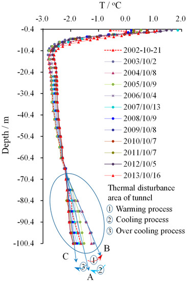
Figure 2.
In-situ geothermal observation of surrounding rock of a permafrost tunnel during the construction and operation process [56].
3.1. Frost Heaving Prevention
3.1.1. Insulation Layer
Thermal insulation materials can control frost heaving by reducing the freezing depth of the surrounding rock of tunnels in seasonally frozen regions. An insulation layer is usually installed on the inner surface of the lining (Figure 3, “Insulation layer (a, black)”) or between the preliminary lining and the secondary lining (Figure 3, “Insulation layer (b, red)”). Both installations have advantages and disadvantages. The insulation layer is easier to break for the former than the latter. If the insulation layer is broken, it is easier to replace for the former than the latter. Thermal insulation efficiency and reduction for the influence of temperature stress on the secondary lining are better for the former than the latter. In addition, there is an off-wall insulation installation referred to in reference [57]. There is a small distance between the insulation layer and the lining when the insulation layer is installed on the surface of the lining. A close air layer is formed between the insulation layer and lining, and it is another insulation layer. There is currently no consensus on the optimal installation, with some believing that the former installation is better [58,59,60,61] and others believing that the latter is better [62]. Depending on the environmental conditions, an insulation layer is usually installed at a specified length from the entrance/exit to the middle of tunnels. For example, an insulation layer was installed 600 m from the entrance and 400 m from the exit to the middle in Galongla tunnel [34,36,37], while an insulation layer was installed 796 m from the east entrance and 786 m from the west entrance toward the middle of Dongnanli tunnel [63]. The basic principle is that the installation length of the insulation layer is generally determined based on the location where the surrounding rock is not frozen in the cold season. The installation length of the insulation layer is largely affected by the ground temperature, inlet wind speed and temperature, atmospheric temperature and ground thermal conductivity [64,65]. Some valuable and specific stipulations are in Technical Specifications for Design and Construction of Highway in Seasonal Frozen Soil Region [66]. Practice has shown that the installation location and length of the insulation layer requires further research considering environmental, geological, hydrological and climatic conditions.
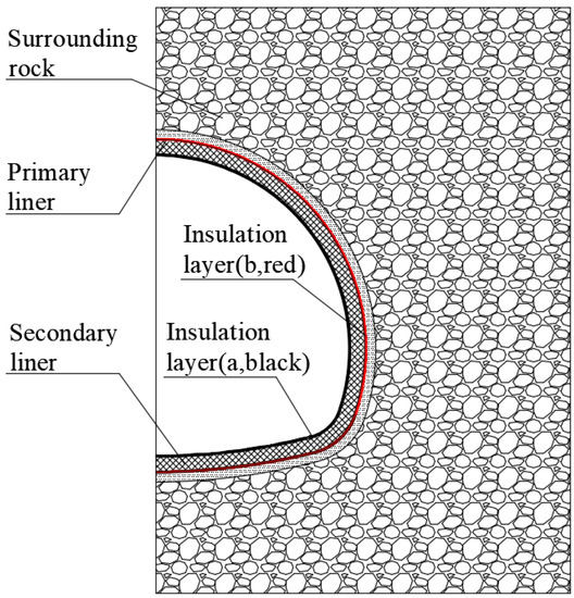
Figure 3.
Layout of insulation layers (Drawed by Y.F. Zhou).
There are many kinds of insulation materials, such as phenolic, polyurethane, polystyrene, high-pressure polyethylene, rubber materials, rock wool, and more. Important material parameters include cold tolerance, thermal conductivity, water absorption, and compressive strength (Table 7), and their cold tolerance is less than the lowest temperature in common cold seasons. Both the thermal conductivity and compressive strengths of phenolic and polyurethane are less than other insulation materials. Their insulation effects are optimal and relatively difficult to crush. Freezing resistance of phenolic and polyurethane is better than the other insulation materials because of their small water absorption [67,68,69].
Table 7.
Performance of insulation materials.
In the experimental investigation of eight materials, polyurethane foam was the optimal insulation material [70]. Thickness and thermal conductivity are the most important design parameters of the insulation layer [59], which are greatly affected by the burial depth, boundary conditions, phase transition, tunnel ventilation conditions, and ground thermal conductivity [71,72,73]. Polyurethane foam board (with a thickness of 3 cm), aluminum silicate fiberboard (2 cm), polyurethane foam board (3 or 4 cm), aluminum silicate fiberboard (3 or 4 cm), and polyphenolic foam board (4 cm) are reasonable selections for Zhegu Mountain tunnel [74]. In reality, different thicknesses have been used in different tunnels because of different environmental conditions and insulation layer materials (Table 8). An insulation layer with a thickness of 5 cm is often used in tunnels, and the most commonly used insulation material is hard polyurethane board. How to simply obtain the reasonable parameters of insulation materials will be a hot spot in the future research. Additionally, new environmentally friendly insulation materials with optimal durability should be studied and applied [75].
Table 8.
Thickness of the insulation layer used in some tunnels.
3.1.2. Heating and Other Measures
Heating is another way to alleviate frost problems of drainage ditches and entrance/exit structures. Geothermal energy, electrical heating, and hot-water supplies have been adopted for heating. The geothermal energy of the surrounding rock in the middle of a tunnel has been used to heat the ditch and lining at the entrance of Linchang tunnel (Figure 4) [81,82,83]. Lai et al. [84] showed that the combination of electric heat tracing (Figure 4) and insulation was a feasible and effective way to prevent frost damage. Heating from the back of the lining was another effective method to prevent freezing damage [39,85]. Additionally, thermal insulation doors (Figure 5) and snow shelters (Figure 6) have been used to increase the air temperature in tunnels in seasonally frozen areas. In-situ test results have revealed that thermal insulation doors are better than snow shelters in preventing frost damage [86,87]. All technologies have advantages and disadvantages (Table 9).
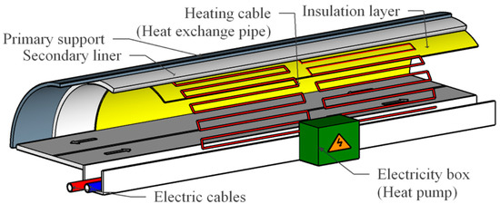
Figure 4.
Heating system using electricity and geothermal energy [77,79].
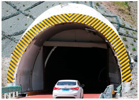
Figure 5.
Thermal insulation gate at the entrance of Yuximolegai tunnel (photographed by Y.F Zhou).
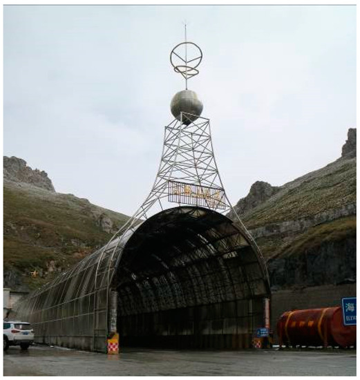
Figure 6.
Snow shelter at the entrance of a tunnel (photographed by Y.F. Zhou).
Table 9.
Comparison of advantages and disadvantages of different technologies.
3.2. Anti-Thawing Measures
During the construction and operation of tunnels in permafrost regions, engineers need to maintain the frozen state of the surrounding rock of tunnels. An insulation layer is therefore used to reduce heat transfer into the surrounding rock [88]. The layout of the insulation layer in a permafrost tunnel is similar to that in a seasonally frozen tunnel (Figure 3). The most important influencing parameters of the insulation layer are thermal conductivity and thickness [29]. An insulation layer with a thermal conductivity of 0.03 W m−1 °C−1 and a thickness of 5 cm was used for Fenghuoshan and Kunlunshan tunnels, and there were no seasonally thawing zones [89,90,91]. Xia et al. [92] obtained an analytical formula for the thickness of the thermal-insulation layer of a permafrost tunnel. Li et al. [93] presented a coupled heat–water model to optimize the parameters of the thermal insulation layer. A thermosyphon was used to prevent permafrost from thawing in part of a permafrost tunnel with small buried depth (Figure 7) [17,94,95]. The thermosyphon technology is a device that uses the conversion convection cycle of liquid and vapor phases to achieve heat transfer [96]. It is a device that uses natural cold energy without external power. It has the characteristics of strong heat transfer ability, small heat transfer temperature difference, low starting temperature, good temperature uniformity, one-way heat transfer, safety and economy. Until now, there are relatively few permafrost tunnel projects, and the accumulated engineering experience is limited. To this end, it is necessary to address the scientific prediction and long-term field monitoring of the thermal field of frozen surrounding rock under climate change and operation conditions.
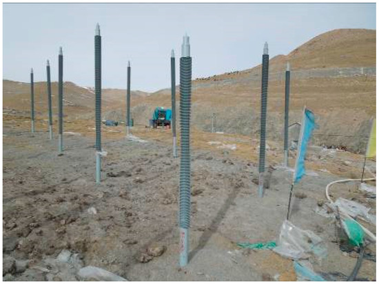
Figure 7.
Thermosyphon used in a tunnel located in permafrost regions (Image supplied by G.Q. Zhang).
3.3. Anti-Icing Measures
Icing is one of the main disaster risks faced by tunnels in cold regions [11]. It occurs in different parts of a tunnel in winter, such as the drainage system, the tunnel portal road, and the lining surface. Drainage tunnels are useless in permafrost tunnels but have been used for sluicing and drainage in unstable frozen and unstable local permafrost tunnels [97]. To prevent the water in drainage pipes from freezing, the ring drain pipes were wrapped with a striped insulating layer at the back of the lining and extended below the road [98]. Tattersall et al. [99] designed a heavy-gauge corrugated liner plate in the form of an arch with an insulation layer. Heating equipment was installed along the roads to melt the ice and snow at the tunnel portals. For example, Lai et al. [78] installed the heating cables in the structural layer of a road. A waterproof and ripped-rock layer was laid between two clay layers for insulation and preventing leakage during the construction of Kunlun mountain tunnel. This measure can prevent the water from icing in the tunnel [33,100]. There is little icing in cold tunnels if the waterproofing system and drainage system work well [101].
4. Tunnel Construction Techniques for Frost Problem Mitigation
Permafrost tunnels are often excavated through drilling and blasting. The stability of the surrounding rock is affected by the thermal disturbance in permafrost regions [102]. If permafrost tunnels are not supported, the thawing depth of the surrounding rock increases over time [103]. Finally, the thawing depth of the surrounding rock exceeds the upper limit of the natural permafrost ground [104]. The plastic area around the tunnel excavation profile and the tensile stress of the lining increases with increase of the thawing depth [105]. After the permafrost tunnel is completed, the thawing depth decreases by refreezing [89]. The freeze–thaw cycles of the thermal disturbance zone are harmful to the surrounding rock and structures. Control methods are thus adopted to reduce the generation of heat. For example, dynamite enwrapped in water or saltwater and brine mud is used in blasting holes [106,107]. The start date of construction is also important for permafrost tunnels. The best time for construction is when the atmospheric temperature is below zero [88]. However, there is no construction thermal disturbance for seasonally frozen tunnels. It is necessary to ensure that there is no gap between the waterproof board and concrete surface or insulation board in seasonally frozen tunnels, because there is more load acting on the lining than usual if there is water to freeze behind the lining. The peeling resistance between the waterproof board and concrete surface or insulation board should be increased as much as possible [108]. If grouting is used in construction, the materials must solidify rapidly, have early strength, and be suitable for sub-zero temperatures [109]. The requirements for construction quality and grouting material are thus high. When transporting and maintaining in winter, the insulation of concrete and shotcrete should be guaranteed. The construction of a permafrost tunnel is thus difficult.
5. Tunnel Maintenance Techniques for Frost Problem Mitigation
The most effective countermeasures to deal with frost damage are the restoration of drainage systems, the reinforcement of structures, and the reinstallation of freezing-prevention systems [6,7,9,110]. For example, the drainage pipes are wrapped with XPS-plates to ensure that the water in pipes does not freeze [6]. An anti-water layer and an anti-freezing layer have been constructed between an old concrete lining and newly added concrete lining [110]. Scaffold rapid construction, corrugated-slide installation, corrugated-plate fixed safety measures, and a corrugated plate combined with a spontaneous bubble polyurethane surface treatment have been adopted [91]. Reasonable parameters of grouting materials and grouting techniques can prevent and control water leakage [111]. The durability and rapid maintenance of materials need to be addressed in future research.
The sufficient and necessary condition for icing is the presence of water. Water may be from groundwater, rainfall, or the melting of ice and snow. Grouting is one of the most effective and popular methods for preventing icing. For example, there is a lot of icing on the road and lining surface in a tunnel (Figure 8) in Xinjiang. Based on investigation and test, the maximum snow thickness is 1.5 m and the maximum frost depth is 1.5 m in the tunnel site, where annual average temperature is 4.7 °C. There was no ice after being treated by grouting (Figure 9). However, it will take time to verify the long-term effectiveness of this approach.
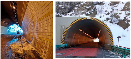
Figure 8.
(Left): before treatment of icing by grouting: (January 2019). (Right): after treatment of icing by grouting: (January 2020) (images supplied by Y.W. Yang).
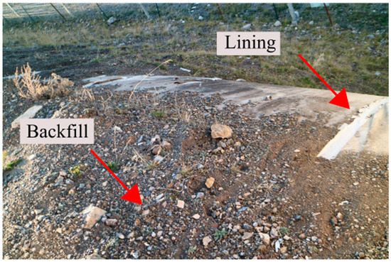
Figure 9.
Backfill soil loss due to freeze–thaw, rain and wind at the top of the open-cut tunnel (photographed by Y.F. Zhou).
There is much frost damage near the entrance/exit of a tunnel especially when the tunnel is partly open-cut. Open-cut tunnels are often built after earth-rock excavation based on the design. An open-cut tunnel is buried by backfilling once it is completed. The backfill at the top of an open-cut tunnel is usually lost under the influence of freezing-thawing, rain, and wind (Figure 9). Changes in atmospheric temperature and seasonal frost heaving of backfill can easily damage the structure. Structures should be buried with backfill until their depths reach the lower freezing limit. The practice of tunnel engineering in cold regions focuses on the frost problems of main structures and does not pay sufficient attention to the frost problems of auxiliary structures, such as the freeze–thaw problems of the drainage ditch at the top of a tunnel entrance and side slope, and the structural defects and durability of the snow shelter. These problems also affect the operation and security of tunnels.
6. Summary
Tunnels in cold regions can suffer freezing and thawing damage because of changes in atmospheric temperature. Theories of tunnel design in cold regions and current techniques for frost problem mitigation in the design, construction, and maintenance of tunnels are reviewed in this paper. The main problem faced by permafrost tunnels is the melting of surrounding rock, which is frost heaving and icing in cold regions. The severity of these problems is determined by the ambient temperature, initial ground temperature, groundwater, and ventilation conditions. Under the background of global warming, the problem of permafrost degradation is becoming prominent. The risks of permafrost tunnels will increase, and the corresponding risk assessment and preventive measures need to be strengthened. For seasonally frozen regions, extreme hot weather and extreme cold weather are also increasing, and the freezing and thawing cycle intensity of tunnel entrance/exit will increase. Additionally, the durability of surrounding rock and lining under large temperature difference also needs to be strengthened.
The freezing and thawing depth and frost heaving force are the most important parameters in the design of tunnels in cold regions. Existing theoretical research and technologies on the frost heaving force and temperature field of tunnels in cold regions have helped solve some problems in practice, but there remain theoretical and technical problems in practice that need to be further studied. As examples: (1) The theory is difficult to understand and use, so it needs to be simplified. (2) The atmospheric parameters at a tunnel site are not usually available because there is no atmosphere observation station. Therefore, this paper proposes to establish atmospheric observation points in the tunnel site area. (3) It is not clear which of the formulas is the most reasonable and how it can be used in design; the theoretical formulas need to be classified. (4) More verification cases need to be carried out. Finally, (5) It is not clear how to adapt to changes in the natural and operating environments, including climate warming.
Techniques for frost problem mitigation in tunnel design include the installation of an insulation layer, heating system, thermal insulation gate, snow shelter, and thermosyphon. An insulation layer is the most commonly adopted option. The reduction of hydration heat and blasting heat is an effective way of decreasing thermal disturbances in the construction of permafrost tunnels. Five issues relating to the mitigation of the freeze–thaw problem need to be addressed: (1) The service life of insulation materials, thermal insulation gates, and snow shelters are not widely verified and the materials that have the same service life as tunnels should be developed. (2) Energy saving techniques and new energy techniques need further research, because the heating systems are expensive and require electricity, which is sometimes unavailable. (3) Effective measures for reducing thermal disturbances and guaranteeing the quality of construction in winter require further study. (4) An evaluation index system of tunnel frost damage is required for further investigation. (5) How to rank the frost damage to new and old tunnels is a difficult problem to solve.
As for the maintenance of tunnels in cold regions, the restoration of the drainage system, the reinforcement of structures, and the reinstallation of freezing-prevention systems are the most effective treatments. In terms of the quality of maintenance, it is necessary to understand the underlying reasons of frost problems, to carry out maintenance as soon as possible to reduce the traffic interruption, and to improve the bonding between new and old materials that have experienced many freeze–thaw cycles.
In addition, the development of new construction materials and grouting materials for cold environments is an important way to improve the service performance of tunnels in cold regions in the future.
Author Contributions
Conceptualization, Y.Z.; Design theory review, M.L. (Min Liu); Construction review, X.Z. and X.S.; Operation and maintenance review, Y.Z. and M.L. (Mingyong Li); writing—original draft preparation, Y.Z. and M.L. (Min Liu); writing—review and editing, Y.Z. and M.L. (Min Liu). All authors have read and agreed to the published version of the manuscript.
Funding
This work was funded by the National Natural Science Foundation of China (51708070).
Institutional Review Board Statement
Not applicable.
Informed Consent Statement
Not applicable.
Data Availability Statement
Some or all data, models, or code that support the findings of this study are available from the corresponding author upon reasonable request.
Conflicts of Interest
The authors declare that they have no known competing financial interests or personal relationships that could have appeared to influence the work reported in this paper.
References
- Tao, Q. Study on Electric Film Heating and Thermal Insulation Technology for Tunnels in Cold Regions. Railw. Eng. 2022, 62, 130–134. [Google Scholar]
- Wan, J.G. Review on and Present Situation and Prospect of Antifreezing Technologies for Tunnels in Cold Areas in China. Tunn. Constr. 2021, 41, 1115–1131. [Google Scholar] [CrossRef]
- Inokuma, A.; Inano, S. Road tunnels in Japan: Deterioration and countermeasures. Tunn. Undergr. Space Technol. 1996, 11, 305–309. [Google Scholar] [CrossRef]
- Jin, H.; Hwang, Y. A Study on Current Extent of Damage of Road Tunnel Lining in Cold Regions (Gangwon-do). J. Korean Geoenviron. Soc. 2017, 18, 49–58. [Google Scholar] [CrossRef]
- Gao, Y.; Zhu, Y.Q.; Zhao, D.P.; Geng, J.Y.; Xin, H. Study on classified suggestion of tunnel in cold region and thermal insulation-considered drainage technology. Chin. J. Rock Mech. Eng. 2018, 37, 3489–3499. [Google Scholar] [CrossRef]
- Aursand, P.O. Frost heave in highway tunnels in Nordland County, Norway. Proc. Int. Conf. Bear. Capacit. Roads Railw. Airfields 2013, 2, 993–1001. [Google Scholar]
- Asakura, T.; Kojima, Y. Tunnel maintenance in Japan. Tunn. Undergr. Space Technol. 2003, 18, 161–169. [Google Scholar] [CrossRef]
- Kang, F.Z.; Qi, F.L.; He, S.H.; Jiang, B. Application of ground penetrating radar to disease detection of Kunlun Mountain tunnel. Chin. J. Rock Mech. Eng. 2010, 29, 3641–3646. [Google Scholar]
- Liu, H.J.; Zheng, J.Y.; Cheng, C.G.; Huang, L.H. Rehabilitation project of the Dabanshan highland road tunnel. J. Chong-Qing Univ. 2011, 34, 138–143+150. [Google Scholar]
- Lv, K.C.; Ji, Z.; Ma, C.C.; Xu, P. Causes and Prevention for Tunnel Lining Crack in Cold Region. Highway 2012, 1, 196–200. [Google Scholar]
- Yu, W.; Zhang, T.; Lu, Y.; Han, F.; Zhou, Y.; Hu, D. Engineering risk analysis in cold regions: State of the art and perspectives. Cold Reg. Sci. Technol. 2019, 171, 102963. [Google Scholar] [CrossRef]
- Zhou, L.C.; Zheng, Y.F.; Li, Z. Study on Mechanism of Circumferential Cracks in cold-region Tunnels. Glob. Geol. 2010, 13, 75–78. [Google Scholar] [CrossRef]
- Jensen, S.F.; Ayele, Y.Z.; Barabadi, A. Fire safety aspects for underwater tunnels in cold climate. In Proceedings of the 27th International Ocean and Polar Engineering Conference, San Francisco, CA, USA, 25–30 June 2017. [Google Scholar]
- Lai, J.; Wang, X.; Qiu, J.; Zhang, G.; Chen, J.; Xie, Y.; Luo, Y. A state-of-the-art review of sustainable energy based freeze proof technology for cold-region tunnels in China. Renew. Sustain. Energy Rev. 2018, 82, 3554–3569. [Google Scholar] [CrossRef]
- Luo, Y.; Chen, J. Research status and progress of tunnel frost damage. J. Traffic Transp. Eng. 2019, 6, 297–309. [Google Scholar] [CrossRef]
- Chen, L.; Yu, W.; Zhang, T.; Yi, X. Asymmetric talik formation beneath the embankment of Qinghai-Tibet Highway triggered by the sunny-shady effect. Energy 2023, 266, 126472. [Google Scholar] [CrossRef]
- Zhang, M.; Pei, W.; Lai, Y.; Niu, F.; Li, S. Numerical study of the thermal characteristics of a shallow tunnel section with a two-phase closed thermosyphon group in a permafrost region under climate warming. Int. J. Heat Mass Transf. 2017, 104, 952–963. [Google Scholar] [CrossRef]
- Shui, W.; Gao, G.; Han, X.; Lv, K. Analysis on thermal conductivity and frost depth of enclosing rock of tunnel in cold region. Undergr. Space 2002, 22, 343–346. [Google Scholar]
- Pei, W.; Yu, W.; Li, S.; Zhou, J. A new method to model the thermal conductivity of soil–rock media in cold regions: An example from permafrost regions tunnel. Cold Reg. Sci. Technol. 2013, 95, 11–18. [Google Scholar] [CrossRef]
- Liu, W.; He, P.; Zhang, Z. A calculation method of thermal conductivity of soils. J. Glaciol. Geocryol. 2002, 24, 770–773. [Google Scholar]
- Côté, J.; Konrad, J.-M. A generalized thermal conductivity model for soils and construction materials. Can. Geotech. J. 2005, 42, 443–458. [Google Scholar] [CrossRef]
- Lai, Y.M.; Liu, S.Y.; Wu, Z.W.; Yu, W.B. Approximate analytical solution for temperature fields in cold regions circular tunnels. Cold Reg. Sci. Technol. 2002, 34, 43–49. [Google Scholar] [CrossRef]
- Zhang, Y.; He, S.; Li, J. Analytic solutions for the temperature fields of a circular tunnel with insulation layer in cold region. J. Glaciol. Geocryol. 2009, 31, 113–118. [Google Scholar]
- Zhang, G.; Xia, C.; Yin, Z. Analytical solution to axial and radial temperature of tunnel in cold region. J. Tongji Univ. (Nat. Sci.) 2010, 38, 1117–1123. [Google Scholar]
- Feng, Q.; Jiang, B. Analytical calculation on temperature field of tunnels in cold region by Laplace integral transform. J. Min. Saf. Eng. 2012, 29, 391–395. [Google Scholar]
- Xia, C.; Lv, Z.; Li, Q.; Huang, J.; Bai, X. Transversely isotropic frost heave of saturated rock under unidirectional freezing condition and induced frost heaving force in cold region tunnels. Cold Reg. Sci. Technol. 2018, 152, 48–58. [Google Scholar] [CrossRef]
- Lai, Y.; Wu, Z.; Zhu, Y.; Zhu, L. Nonlinear analysis for the coupled problem of temperature, seepage and stress fields in cold-region tunnels. Tunn. Undergr. Space Technol. 1998, 13, 435–440. [Google Scholar] [CrossRef]
- Lai, Y.-M.; Wu, Z.; Zhu, Y.; Zhu, L. Nonlinear analysis for the coupled problem of temperature and seepage fields in cold regions tunnels. Cold Reg. Sci. Technol. 1999, 29, 89–96. [Google Scholar] [CrossRef]
- Zhang, X.F.; Lai, Y.M.; Yu, W.B.; Zhang, S.J. Nonlinear analysis for the three-dimensional temperature fields in cold region tunnels. Cold Reg. Sci. Technol. 2002, 35, 207–219. [Google Scholar] [CrossRef]
- Zhang, X.; Lai, Y.; Yu, W.; Zhang, S. Numerical analysis for the three-dimension temperature fields in cold region tunnels. J. China Railw. Soc. 2003, 25, 84–90. [Google Scholar]
- Lai, Y.; Zhang, X.; Yu, W.; Zhang, S.; Liu, Z.; Xiao, J. Three-dimensional nonlinear analysis for the coupled problem of the heat transfer of the surrounding rock and the heat convection between the air and the surrounding rock in cold-region tunnel. Tunn. Undergr. Space Technol. 2005, 20, 323–332. [Google Scholar] [CrossRef]
- Yang, G.; Zhou, C.; Tian, Y. Numerical simulation and analysis of moisture-heat coupling for soft rock tunnel in cold regions. Yantu Lixue (Rock Soil Mech.) 2006, 27, 1258–1262. [Google Scholar]
- Zhang, Q.; Gao, G.; Yang, G. Three-dimensional finite difference analysis of the temperature field of cold-region tunnels. J. Univ. Sci. Technol. Suzhou Eng. Technol. 2006, 19, 15–20. [Google Scholar]
- Tan, X.; Chen, W.; Tian, H.; Cao, J. Water flow and heat transport including ice/water phase change in porous media: Numerical simulation and application. Cold Reg. Sci. Technol. 2011, 68, 74–84. [Google Scholar] [CrossRef]
- Tan, X.; Chen, W.; Wu, G.; Yang, J. Numerical simulations of heat transfer with ice–water phase change occurring in porous media and application to a cold-region tunnel. Tunn. Undergr. Space Technol. 2013, 38, 170–179. [Google Scholar] [CrossRef]
- Tan, X.; Chen, W.; Wu, G.; Yang, J. Study of airflow in a cold-region tunnel using a standard k − ε turbulence model and air-rock heat transfer characteristics: Validation of the CFD results. Heat Mass Transf. 2012, 49, 327–336. [Google Scholar] [CrossRef]
- Tan, X.; Chen, W.; Yang, D.; Dai, Y.; Wu, G.; Yang, J.; Yu, H.; Tian, H.; Zhao, W. Study on the influence of airflow on the temperature of the surrounding rock in a cold region tunnel and its application to insulation layer design. Appl. Therm. Eng. 2014, 67, 320–334. [Google Scholar] [CrossRef]
- Zhou, X.; Zeng, Y.; Fan, L. Temperature field analysis of a cold-region railway tunnel considering mechanical and train-induced ventilation effects. Appl. Therm. Eng. 2016, 100, 114–124. [Google Scholar] [CrossRef]
- Jin, H.; Kim, T.; Hwang, Y. Analysis of Temperature Change of Tunnel Lining with Heating Element. J. Korean Geoenviron. Soc. 2017, 18, 5–12. [Google Scholar] [CrossRef]
- Lai, Y.; Hui, W.; Wu, Z.; Liu, S.; Den, X. Analytical viscoelastic solution for frost force in cold-region tunnels. Cold Reg. Sci. Technol. 2000, 31, 227–234. [Google Scholar] [CrossRef]
- Lai, Y.; Wu, Z.; Zhu, Y.; Zhu, L. Elastic visco-plastic analysis for earthquake response of tunnels in cold regions. Cold Reg. Sci. Technol. 2000, 31, 175–188. [Google Scholar] [CrossRef]
- Gao, G.; Chen, Q.; Zhang, Q.; Chen, G. Analytical elasto-plastic solution for stress and plastic zone of surrounding rock in cold region tunnels. Cold Reg. Sci. Technol. 2011, 72, 50–57. [Google Scholar] [CrossRef]
- Feng, Q.; Jiang, B.-S.; Zhang, Q.; Wang, L.-P. Analytical elasto-plastic solution for stress and deformation of surrounding rock in cold region tunnels. Cold Reg. Sci. Technol. 2014, 108, 59–68. [Google Scholar] [CrossRef]
- Feng, Q.; Liu, W.-W.; Jiang, B.-S. Analytical solution for the stress and deformation of rock surrounding a cold-regional tunnel under unequal compression. Cold Reg. Sci. Technol. 2017, 139, 1–10. [Google Scholar] [CrossRef]
- Huang, S.; Liu, Q.; Cheng, A.; Liu, Y. A statistical damage constitutive model under freeze-thaw and loading for rock and its engineering application. Cold Reg. Sci. Technol. 2018, 145, 142–150. [Google Scholar] [CrossRef]
- Wang, J.Y.; Hu, Y.F. A discussion on frost-heaving force on tunnel lining. J. Glaciol. Geocryol. 2004, 26, 112–119. [Google Scholar]
- Fan, L.; Zeng, Y.; He, C.; Cheng, X. Magnitude and Distribution of Frost Heave Force for Cold Region Strong Rock Tunnels. China Railw. Sci. 2007, 28, 44–49. [Google Scholar]
- Kang, Y.; Liu, Q.; Zhao, J.; Zhang, F. Research on frost deformation characteristics of rock and simulation of tunnel frost deformation in cold region. Chin. J. Rock Mech. Eng. 2012, 31, 2518–2526. [Google Scholar]
- Tan, X.; Chen, W.; Wu, G.; Zheng, P. Study of thermo-hydro-mechanical-damage (THMD) coupled model in the condition of freeze-thaw cycles and its application to cold region tunnels. Chin. J. Rock Mech. Eng. 2013, 32, 239–250. [Google Scholar] [CrossRef]
- Huang, J.; Xia, C.; Han, C.; Huang, M. Analytical solution of frost heave force acting on cold-region tunnel liner considering anisotropy frost heave of surrounding rock. Yanshilixue Yu Gongcheng Xuebao 2015, 34, 3766–3774. [Google Scholar] [CrossRef]
- Huang, J.; Xia, C.; Han, C.; Li, Z. Distribution and simplified calculation method of the frost heaving force of highway tunnels in cold regions. Mod. Tunn. Technol. 2016, 53, 63–70. [Google Scholar] [CrossRef]
- Xia, C.; Huang, J.; Han, C.; Tang, Z. Methods of frost-heave ratio evaluation and classification of frost-heave susceptibility of tunnel surrounding rocks in cold regions. Chin. J. Rock Mech. Eng. 2013, 32, 1876–1885. [Google Scholar]
- Yuan, Y.; Lai, Y. The Identification and Classification of Freezing-Thawing and Frozen Environments for the Surrounding Rocks of Tunnels in Cold Regions. Mod. Tunn. Technol. 2016, 53, 19–25. [Google Scholar] [CrossRef]
- Zhang, G.; Xia, C.; Sun, M.; Zou, Y.; Xiao, S. A new model and analytical solution for the heat conduction of tunnel lining ground heat exchangers. Cold Reg. Sci. Technol. 2013, 88, 59–66. [Google Scholar] [CrossRef]
- Zeng, Y.; Liu, K.; Zhou, X.; Fan, L. Tunnel temperature fields analysis under the couple effect of convection-conduction in cold regions. Appl. Therm. Eng. 2017, 120, 378–392. [Google Scholar] [CrossRef]
- Yu, W.; Lu, Y.; Han, F.; Liu, Y.; Zhang, X. Dynamic process of the thermal regime of a permafrost tunnel on Tibetan Plateau. Tunn. Undergr. Space Technol. 2018, 71, 159–165. [Google Scholar] [CrossRef]
- Fan, D.; Xia, C.; Han, C. Option of laying position of insulation layer for tunnel in frost region. Chin. J. Undergr. Space Eng. 2014, 10, 391. [Google Scholar]
- Hao, F.; Sun, Q.S. Research on the Temperature Fields and Insulating Layers of Highway Tunnels in a Cold Region. Mod. Tunn. Technol. 2012, 49, 39–43. [Google Scholar] [CrossRef]
- Ma, Q.; Luo, X.; Lai, Y.; Niu, F.; Gao, J. Numerical investigation on thermal insulation layer of a tunnel in seasonally frozen regions. Appl. Therm. Eng. 2018, 138, 280–291. [Google Scholar] [CrossRef]
- Wang, Z.H.; Zhang, Y.N.; She, X.K.; Dong, F.R.; Wang, S.H. Surrounding Rock Insulation Measures for Construction of Four-season Cross-country Skiing Tunnel. J. Water Resour. Archit. Eng. 2019, 17, 177–180+198. [Google Scholar]
- Yuan, J.X.; Wang, D.Y.; Ma, H.L. Study on Thermal Insulation Technology of Insulation Layer of Tunnels in Seasonal Frozen Soil Area. Railw. Stand. Des. 2018, 62, 100–105. [Google Scholar] [CrossRef]
- Chen, J.X.; Luo, Y.B. Calculation method of antifreezing layer thickness in cold region tunnel. J. Traffic Transp. Eng. 2007, 7, 76–79. [Google Scholar]
- Fan, H. Computational Optimization of the Insulation Parameter of Freeze-proof Separate Lining in Cold-region Tunnel. J. Inf. Comput. Sci. 2015, 12, 6201–6208. [Google Scholar] [CrossRef]
- Lu, T.; Zhang, G.; Liu, S.; Zheng, B.; Zhang, X. Numerical investigation of the temperature field and thermal insulation design of cold-region tunnels considering airflow effect. Appl. Therm. Eng. 2021, 191, 116923. [Google Scholar] [CrossRef]
- Yu, L.; Sun, Y.; Wang, M.N. Research on the calculation method for frost-resistance fortification lengths of tunnels in cold regions. Mod. Tunn. Technol. 2021, 58, 21–28. [Google Scholar] [CrossRef]
- Ministry of Transport of the People’s Republic of China. Technical Specifications for Design and Construction of Highway in Seasonal Frozen Soil Region: JTG/T D31-06-2017; China Communication Press: Beijing, China, 2018.
- Li, Y.; Sun, Y.; Zhuang, Y.; Duan, L.; Xie, K. Thermal Conductivity Characteristics of Thermal Insulation Materials Immersed in Water for Cold-Region Tunnels. Adv. Mater. Sci. Eng. 2020, 2020, 9345615. [Google Scholar] [CrossRef]
- Amin, S.; Heweidak, M. Phenolic Foams: The Insulating Materials to Reduce the Frost Penetration, Skidding, and Flooding Risk of Road and Airfield Pavements. In Phenolic Based Foams: Preparation, Characterization, and Applications; Springer Nature: Singapore, 2022; pp. 359–369. [Google Scholar] [CrossRef]
- Chen, Y.; Wang, S.; Guo, C.; Lin, C.; Zhao, C. Analyses of non-aqueous reactive polymer insulation layer in high geothermal tunnel. J. Rock Mech. Geotech. Eng. 2022, 15, 169–178. [Google Scholar] [CrossRef]
- Chen, J.X.; Zan, Y.J. Field test and analysis of antifreezing thermal protective layer effect of the highway tunnel in cold area. China J. Highw. Transp. 2001, 14, 75–79. [Google Scholar] [CrossRef]
- Son, H.S.; Jun, K.J.; Yune, C.Y. Analysis on Freezing Reduction of Road Tunnels with Heat Insulation Method during Winter. J. Korean Geotech. Soc. 2017, 33, 17–27. [Google Scholar] [CrossRef]
- Yan, Q.; Li, B.; Zhang, Y.; Yan, J.; Zhang, C. Numerical Investigation of Heat-Insulating Layers in a Cold Region Tunnel, Taking into Account Airflow and Heat Transfer. Appl. Sci. 2017, 7, 679. [Google Scholar] [CrossRef]
- Zhou, Y.; Zhang, X.; Deng, J. A mathematical optimization model of insulation layer’s parameters in seasonally frozen tunnel engineering. Cold Reg. Sci. Technol. 2014, 101, 73–80. [Google Scholar] [CrossRef]
- Xie, H.Q.; He, C.; Li, Y.L. Study on insulating layer thickness by phase-change temperature field of highway tunnel in cold region. Chin. J. Rock Mech. Eng. 2007, 26, 4395–4401. [Google Scholar]
- Li, Y.; Sun, Y.; Qiu, J.; Liu, T.; Yang, L.; She, H. Moisture absorption characteristics and thermal insulation performance of thermal insulation materials for cold region tunnels. Constr. Build. Mater. 2020, 237, 117765. [Google Scholar] [CrossRef]
- Broch, E.; Grøv, E.; Davik, K.I. The inner lining system in Norwegian traffic tunnels. Tunn. Undergr. Space Technol. 2002, 17, 305–314. [Google Scholar] [CrossRef]
- Yan, Q.X.; Chuan, H.; Zeng, D.Y. Study of temperature field and heat preservation and insulation layer for tunnel in cold area. Adv. Eng. Sci. 2005, 37, 24–27. [Google Scholar]
- Lai, J.; Qiu, J.; Chen, J.; Fan, H.; Wang, K. New Technology and Experimental Study on Snow-Melting Heated Pavement System in Tunnel Portal. Adv. Mater. Sci. Eng. 2015, 2015, 706536. [Google Scholar] [CrossRef]
- Feng, Q.; Jiang, B.-S.; Zhang, Q.; Wang, G. Reliability research on the 5-cm-thick insulation layer used in the Yuximolegai tunnel based on a physical model test. Cold Reg. Sci. Technol. 2016, 124, 54–66. [Google Scholar] [CrossRef]
- Wang, T.; Zhou, G.; Wang, J.; Yin, L. Stochastic analysis of uncertainty mechanical characteristics for surrounding rock and lining in cold region tunnels. Cold Reg. Sci. Technol. 2018, 145, 160–168. [Google Scholar] [CrossRef]
- Zhang, G.Z.; Xia, C.C.; Ma, X.G.; Li, P.; Wei, Q. Rock-soil thermal response test of tunnel heating system using heat pump in cold region. Chin. J. Rock Mech. Eng. 2012, 31, 99–105. [Google Scholar]
- Zhang, G.; Guo, Y.; Zhou, Y.; Ye, M.; Chen, R.; Zhang, H.; Yang, J.; Chen, J.; Zhang, M.; Lian, Y.; et al. Experimental study on the thermal performance of tunnel lining GHE under groundwater flow. Appl. Therm. Eng. 2016, 106, 784–795. [Google Scholar] [CrossRef]
- Zhang, H.M.; Cao, H.B.; Zhang, M.J. Analysis of Temperature Field of the Tunnel Surrounding Rock in Cold Regions. Adv. Mater. Res. 2013, 753–755, 745–749. [Google Scholar] [CrossRef]
- Lai, J.; Qiu, J.; Fan, H.; Chen, J.; Xie, Y. Freeze-proof method and test verification of a cold region tunnel employing electric heat tracing. Tunn. Undergr. Space Technol. 2016, 60, 56–65. [Google Scholar] [CrossRef]
- Wu, Y.M.; Li, W.B.; Fu, H.L.; Wang, B.S.; Liu, B. Frost protection system of heating from back of lining for tunnel in cold region and its control model. Electron. J. Geotech. Eng. 2013, 18, 5479–5490. [Google Scholar]
- Lai, Y.M.; Wu, Z.W.; Zhang, S.J.; Yu, W.B.; Den, Y.S. In-situ observed study for the effect of heat preservation in cold regions tunnels. J. China Railw. Soc. 2003, 25, 81–86. [Google Scholar]
- Wu, Z.; Zhang, S.; Yu, W.; Deng, Y. Study of Methods to Control Frost Action in Cold Regions Tunnels. J. Cold Reg. Eng. 2003, 17, 144–152. [Google Scholar] [CrossRef]
- Zhang, X.; Lai, Y.; Yu, W.; Zhang, S. Non-linear analysis for the freezing–thawing situation of the rock surrounding the tunnel in cold regions under the conditions of different construction seasons, initial temperatures and insulations. Tunn. Undergr. Space Technol. 2002, 17, 315–325. [Google Scholar] [CrossRef]
- Zhang, X.F.; Yu, W.B. Forecast analysis for the re-frozen of Kunlunshan Tunnel on Qing-Tibet railway. China J. High-Way Transp. 2005, 18, 67–71+82. [Google Scholar] [CrossRef]
- Zhang, X.F.; Zhang, M.X.; Yang, F.C. Nonlinear analysis on temperature characteristics of Fenghuo Mountain tunnel. Chin. J. Geotech. Eng. 2009, 31, 1680–1685. [Google Scholar]
- Zhang, Y.; Lai, Y.M.; Zhang, X.F. A practical method for calculating the design parameters of the heat insulation layer in cold region tunnel. China Railw. Sci. 2009, 30, 66–70. [Google Scholar] [CrossRef]
- Xia, C.C.; Fa, D.F.; Li, Z.H.; He, J. Discussion on analytical calculation for thermal-insulation layer thickness of tunnel in perma-frost area. China Civ. Eng. J. 2015, 48, 118–124. [Google Scholar] [CrossRef]
- Li, S.; Niu, F.; Lai, Y.; Pei, W.; Yu, W. Optimal design of thermal insulation layer of a tunnel in permafrost regions based on coupled heat-water simulation. Appl. Therm. Eng. 2017, 110, 1264–1273. [Google Scholar] [CrossRef]
- Liu, K.; Cai, H.C.; Li, F. Application of Thermal Probe Group in Protection of Shallow Section of Tunnel in Permafrost Area. J. Railw. Eng. Soc. 2013, 30, 60–64. [Google Scholar]
- Mainali, G.; Dineva, S.; Nordlund, E. Experimental study on debonding of shotcrete with acoustic emission during freezing and thawing cycle. Cold Reg. Sci. Technol. 2015, 111, 1–12. [Google Scholar] [CrossRef]
- Wang, F.; Li, G.; Alexander, F.; Ma, W.; Chen, D.; Wu, G.; Mu, Y.; Wang, X.; Jing, H.; Zhang, Z. Applicability analysis of thermosyphon for thermally stabilizing pipeline foundation perma-frost and its layout optimization. Cold Reg. Sci. Technol. 2023, 208, 103769. [Google Scholar] [CrossRef]
- Xia, C.C.; He, J.; Fan, D.F. Roles and structures of cold-proof drainage tunnels for different permafrost tunnels. Mod. Tunn. Technol. 2017, 54, 1–8. [Google Scholar] [CrossRef]
- Lv, K.C.; Ma, C.C.; Ji, Z.; Xu, P. Analysis on stripe insulating layer for ring drain pipe of tunnel in cold region and its temperature field. Chin. J. Undergr. Space Eng. 2013, 9, 304–308. [Google Scholar]
- Tattersall, C.; Mitchells, R.; Gallion, E.; Weller, R. Water and Ice Control in the Anton Anderson Memorial Tunnel. In Cold Regions Engineering: Cold Regions Impacts on Transportation and Infrastructure; American Society of Civil Engineers: Anchorage, AK, USA, 2002; pp. 219–229. [Google Scholar]
- Zhang, X.; Zhang, Y. Study on a new-styled measure for treating water leakage of the permafrost tunnels. Tunn. Undergr. Space Technol. 2006, 21, 656–667. [Google Scholar] [CrossRef]
- Zhang, Y.; Xia, C.; Zhou, S.; Hu, Y.; Zhang, J. A new sustainable energy based freeze proof method for drainage system in cold-region tunnels: A case study of Tianshan Shengli Tunnel. Case Stud. Therm. Eng. 2022, 34, 102020. [Google Scholar] [CrossRef]
- Huang, S.L.; Aughenbaugh, N.B.; Wu, M. Stability Study of Crrel Permafrost Tunnel. J. Geotech. Eng. 1986, 112, 777–790. [Google Scholar] [CrossRef]
- Jia, X.Y.; Zhu, Y.Q.; Li, W.J. Study of the temperature field of the surrounding rock during the tunnel construction in permafrost regions. Traffic Eng. Technol. Natl. Def. 2003, 4, 42–45. [Google Scholar] [CrossRef]
- Zhang, D.H.; Wang, M.S.; Ren, S.Q. Experimental study on temperature and response of seasonal active layer of tunnels sur-rounding rock in permafrost region on Qinghai-Tibet plateau. Chin. J. Rock Mech. Eng. 2007, 26, 614–619. [Google Scholar]
- Jia, X.Y.; Li, W.J.; Zhu, Y.Q. Analysis of stability for surrounding rock caused by depth of thawing range during plateau perma-frost tunnel construction. Chin. J. Rock Mech. Eng. 2005, 24, 5693–5697. [Google Scholar]
- Chu, H.B.; Yang, X.L.; Liang, W.M.; Yu, Y.Q.; Huang, X.G. Choose of Liquid Medium for Compound Non-coupling Charging for Frozen Soil Tunnel. Min. Metall. Eng. 2007, 27, 5–8. [Google Scholar]
- Tan, Z.S.; Kuang, C.M.; Yang, X.L.; Wang, M.S. Research on Blasting Technology for Construction of Fenghuoshan Tunnel in Permafrost. Chin. J. Rock Mech. Eng. 2006, 25, 1056–1061. [Google Scholar]
- Zhou, J.Z. Constructing technology research on water-proof/drainage and heat insulation lining in kunlunshan tunnel of qinghai-tibet railway, tibetan plateau. J. Glaciol. Geocryol. 2003, 25, 106–111. [Google Scholar]
- Liu, G.Y. Tunnel construction technology for the high altitude and the high and cold area. China Railw. Sci. 2001, 4, 50–55. [Google Scholar]
- Chen, J.X. Technique of preventing frost damage in highway tunnel. J. Chang. Univ. (Nat. Sci. Ed.) 2006, 26, 68–70. [Google Scholar] [CrossRef]
- Li, C.F.; Mei, Z.R. Research on leakage prevention techniques for tunnels embedded in frozen ground and located in bitter cold plateau. Mod. Tunn. Technol. 2005, 4, 44–49. [Google Scholar] [CrossRef]


Disclaimer/Publisher’s Note: The statements, opinions and data contained in all publications are solely those of the individual author(s) and contributor(s) and not of MDPI and/or the editor(s). MDPI and/or the editor(s) disclaim responsibility for any injury to people or property resulting from any ideas, methods, instructions or products referred to in the content. |
© 2023 by the authors. Licensee MDPI, Basel, Switzerland. This article is an open access article distributed under the terms and conditions of the Creative Commons Attribution (CC BY) license (https://creativecommons.org/licenses/by/4.0/).