Article

Automated Sampling System for Monitoring 85Kr in Air

1
Environmental Radioactivity Assessment Team, Korea Atomic Energy Research Institute, 111 Daedeokdae-ro 989 beongil, Yuseong-gu, Daejeon 34057, Republic of Korea
2
Nuclear Science and Technology, University of Science and Technology, 217, Gajeong-ro, Yuseong-gu, Daejeon 34113, Republic of Korea
*
Author to whom correspondence should be addressed.
Atmosphere 2023, 14(7), 1103; https://doi.org/10.3390/atmos14071103
Submission received: 31 May 2023 / Revised: 22 June 2023 / Accepted: 27 June 2023 / Published: 1 July 2023
(This article belongs to the Section Atmospheric Techniques, Instruments, and Modeling)

Abstract

:
Radioactive krypton-85 (85Kr) gas, a chemically inert and non-proliferation indicator, is derived from fission products. Its detection relies on the Budesamt für Strahlenschutz–Institute of Atmospheric Radioactivity (BfS-IAR) method, which necessitated impurity removal using soda lime, silica gel, and liquid nitrogen for cryogenic adsorption. This manual process requires frequent replacements, posing challenges for its automation. To address this, we developed a prototype krypton sampling system as an interim research product for the fully automated remote monitoring of covert nuclear activity. The system incorporates a hollow fiber membrane for impurity removal, a computer-controlled multi-position valve for sampling, and an electric cooler for adsorption. The impurity removal modules demonstrated high efficiencies, removing H2O and CO2 at 99.8% and 97.8% rates, respectively. Further, the custom-made sampling system can process 16 samples in a single run without analyst intervention. We conducted experiments to verify the automatic krypton sampling capability. The activity concentration of 85Kr in ambient air was measured using the BfS-IAR processing and detection system. The system exhibited a recovery rate of ~7.8% for krypton in 1000 L air, demonstrating good continuous remote monitoring capability. This study promotes the development of an automated analysis system for the detection of 85Kr in ambient air.

1. Introduction

The radioactive noble gas krypton-85 (85Kr) is a fission product of uranium and plutonium with a moderately long half-life of 10.76 years. Currently, the major sources of 85Kr in the atmosphere are anthropogenic, including nuclear weapons testing, nuclear reactors, and nuclear fuel reprocessing facilities located in the Northern Hemisphere [1,2,3]. Interestingly, no effective reduction mechanism exists for 85Kr other than radioactive decay because 85Kr is chemically inert. Owing to its long half-life and inertness, 85Kr has accumulated and spread throughout the atmosphere of the earth. For this reason, 85Kr is used as a tracer in environmental studies, in which radiokrypton-based chronometers (85Kr/Kr, 81Kr/Kr) surpass other hydrological tracers (e.g., 3H–He, CFCs, and SF6) [4,5].
Moreover, the continuous monitoring of radioactive noble gases such as 85Kr and Xe isotopes is an important and reliable method to detect clandestine nuclear activities in surrounding countries [6,7]. Noble gases are released when nuclear fuel rods are cut during reprocessing, which subsequently raises the 85Kr concentration past the average concentration in the atmosphere. The monitoring of 85Kr in the air has sufficient scientific value for nuclear non-proliferation and is an indicator of clandestine plutonium production [8,9]. Therefore, an 85Kr measurement system for continuous monitoring is required to reliably measure 85Kr activity concentration levels both globally and locally.
Considerable research has been conducted to develop a system that analyzes radioactive Kr concentration in the atmosphere. To date, the only commercially used instrument for radioactivity measurements of 85Kr in the atmosphere is the Budesamt für Strahlenschutz—Institute of Atmospheric Radioactivity (BfS-IAR) system [2,10]. The BfS-IAR system is a manual analysis instrument that performs gas capture and analysis. It consists of three main parts: sampling, processing (concentration and purification), and quantification. For air sampling, activated charcoal is used to capture 85Kr from the air at cryogenic conditions with liquid nitrogen (LN2, boiling point of −195.8 °C). To avoid Kr uptake deterioration by activated charcoal during sampling, CO2 and H2O must be removed before the air enters the cryogenic adsorption module. In the BfS-IAR system, soda lime and silica gel are applied for CO2 and H2O removal. The sample containing 85Kr gas is then transferred into an aluminum cylinder and concentrated. The concentrated gas sample is subsequently transferred into a U-tube containing activated charcoal for N2 and O2 removal via temperature control and separated into 85Kr and Xe isotopes using separation gas chromatography (GC). The purified 85Kr and Xe isotopes are analyzed using proportional gas counters applied with 10 cm Pb-shielding and anti-coincidence systems.
Recently, a new method for 85Kr detection using atom-trap-trace-analysis (ATTA) was reported by Chen et al., and it has been applied in diverse hydrology and paleoclimate studies as radiokrypton-based chronometers [5,11,12]. ATTA is an emerging technique used to detect rare isotopes by counting individual atoms. In addition, it is advantageous compared to conventional methods as it requires significantly fewer air samples to sufficiently determine the Kr isotope ratios. In addition, a more advanced technique for measuring 85Kr using mass spectrometry and ATTA has been developed, but its access is limited, and it is inappropriate and impractical for the routine and continuous detection of covert nuclear activities in the atmosphere.
Igarashi et al. developed an 85Kr measurement system for continuous monitoring based on the BfS-IAR system [13]. In this system, the sampling parts of the BfS-IAR system were used as is, whereas the purification and quantifications of 85Kr following gas capture by three GC and Geiger–Müller tubes were automated for the continuous monitoring of 85Kr in air. Gas chromatographic separation and gas activity evaluation in the BfS-IAR system were performed manually. Therefore, the automated separation and quantification process is a novel and notable advancement for the continuous and routine monitoring of 85Kr in the ambient air.
We aimed to develop an automated 85Kr sampling system to overcome the limitations of conventional systems, specifically the BfS-IAR system. Conventional krypton sampling systems are usually installed and operated at remote locations proximate to the source, for example, in border regions, for effective krypton detection. Therefore, it is difficult to access and requires a lot of time and manpower. On the other hand, an automated system allows a shorter sample collection cycle time during remote monitoring, thereby enhancing its monitoring capabilities and time resolution. In this study, we built an automated Kr sampling system, which has not been studied yet, for the periodic remote detection of nuclear reprocessing. For this purpose, a hollow fiber membrane module was applied to remove CO2 and H2O from the collected air, overcoming the limitations of soda lime and silica gel in conventional systems. In addition, we built an automated sample distribution module with a multi-position valve (MPV) and an adsorption system using an electric low-temperature (−80 ℃) cooling method instead of the cryogenic adsorption method. We evaluated the low-temperature cooling collection performance of the developed system using Kr standard gas mixtures with varied concentrations and volumes. This custom-made, automated Kr sampling system was verified by detecting 85Kr in ambient air.

2. Materials and Methods

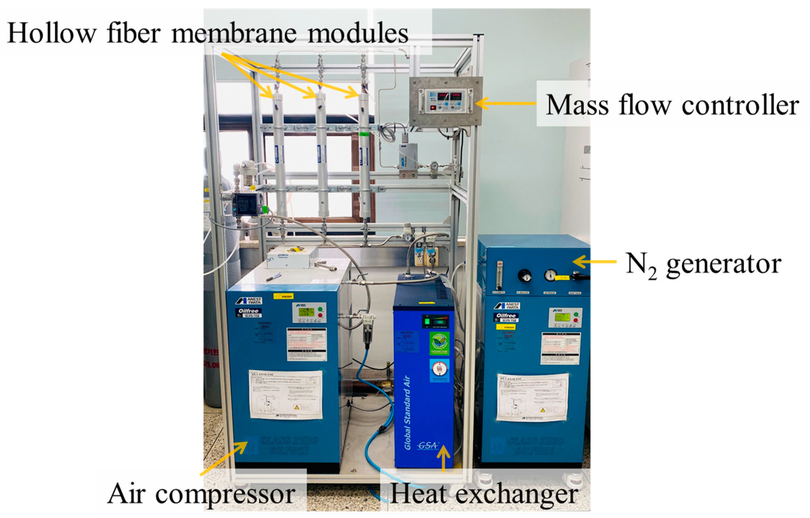
2.1. Reagents and Instrumentation

Figure 1 shows schematics of the sampling part of the conventional and proposed systems. The existing commercial BfS-IAR system uses soda lime and silica gel to remove CO2 and H2O before ambient air sampling, as shown in Figure 1a. Soda lime, composed of CaO, reacts with CO2 to form CaCO3, whereas silica gel, a porous material composed of SiO2·n(H2O), removes H2O from air owing to its strong hygroscopicity. In the conventional system, the analyst replaces the materials when the volume of the soda lime and the color of the silica gel change. Soda lime and silica gel are generally replaced after five and one sampling cycles. However, this is mainly based on the experience of the analysts rather than a quantitative evaluation. This is disadvantageous as the replacement cycle must be changed according to the sampling period and the environmental conditions, such as humidity. The impurity-removed air is then transferred to an adsorption module mounted on the LN2 dewar and adsorbed onto the activated charcoal. In addition, LN2 must be periodically replenished in the dewar to maintain a cryogenic environment.
The proposed system removes CO2 and H2O from the air using a hollow fiber membrane that can be easily operated, controlled, and scaled up. Before introducing the air sample to the hollow fiber membrane, some H2O from the air sample was removed through the air compressor and heat exchanger, and the remaining CO2 and H2O were removed from the hollow fiber membrane (Figure 1b). An N2 generator was used to remove the moisture remaining on the surface of the hollow fiber and maintain impurity removal performance. The sampled air was then transferred to the desired adsorption module mounted on the custom-made electric cooler through a sample distribution system using an MPV (VICI, Schenkon, Switzerland) and was subsequently absorbed into the activated charcoal. This reduces the need for analyst intervention and allows the annual replacement of hollow fiber membranes, enabling long-term and reliable operation of the impurity removal system. Activated charcoal with a diameter of 0.3–0.5 mm (Merck, Darmstadt, Germany), polysulfone hollow fiber membrane (MMD-1522A, Airrane, Cheongju-si, Republic of Korea), and standard gas (N2-balanced Kr (5, 10, 100 ppm), He-balanced Kr (100 ppm)) with a purity of 99.999% (Noble Gas, Daejeon, Republic of Korea) was used as the reagents. The details of each configuration are described in Section 2.2.

2.2. System Configuration

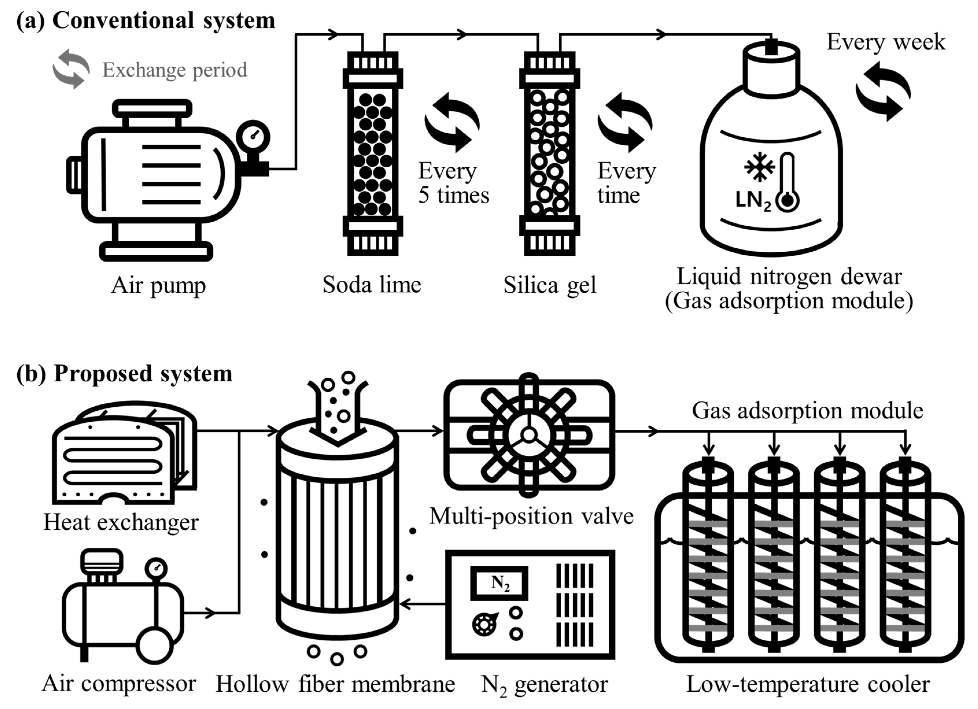
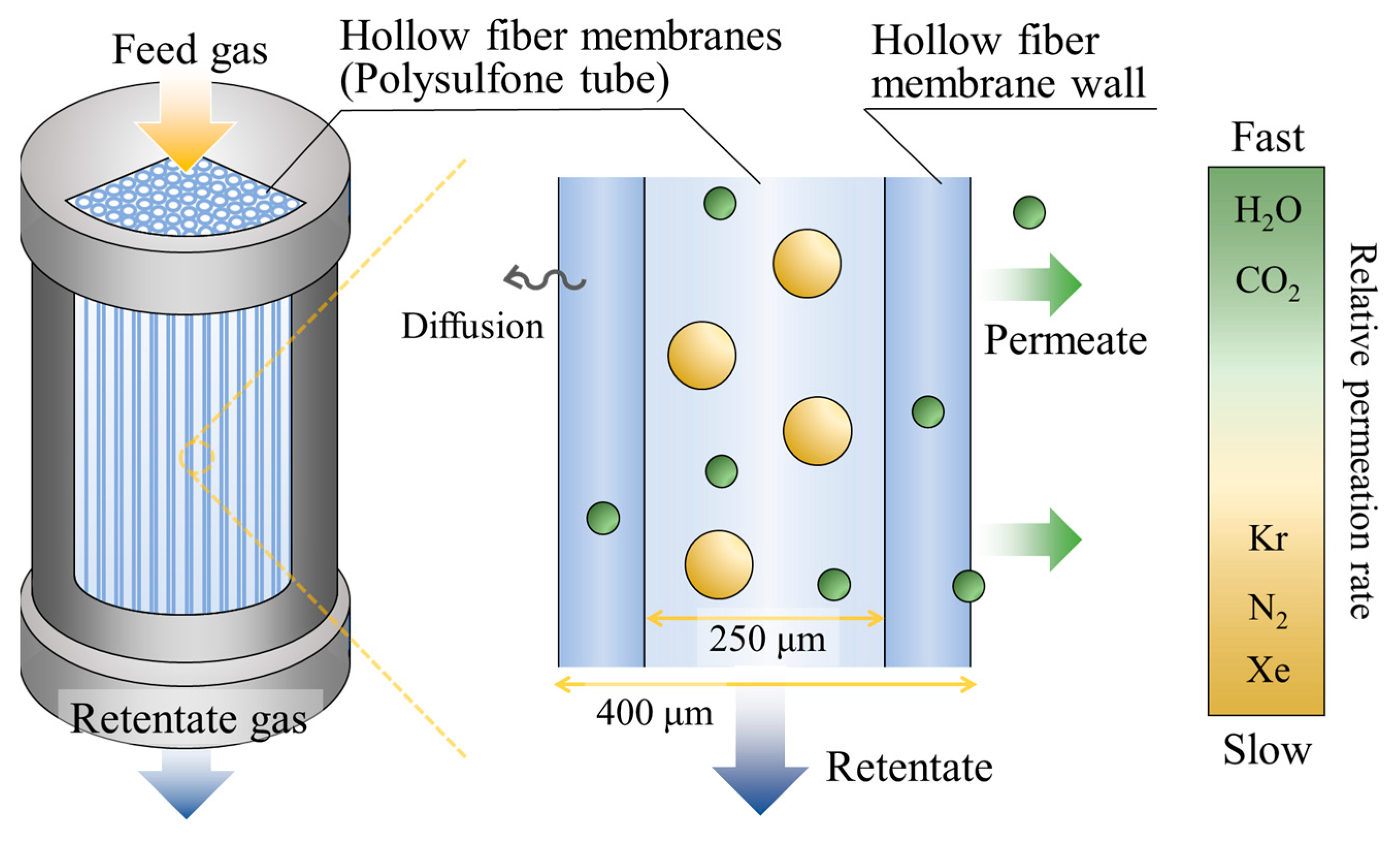
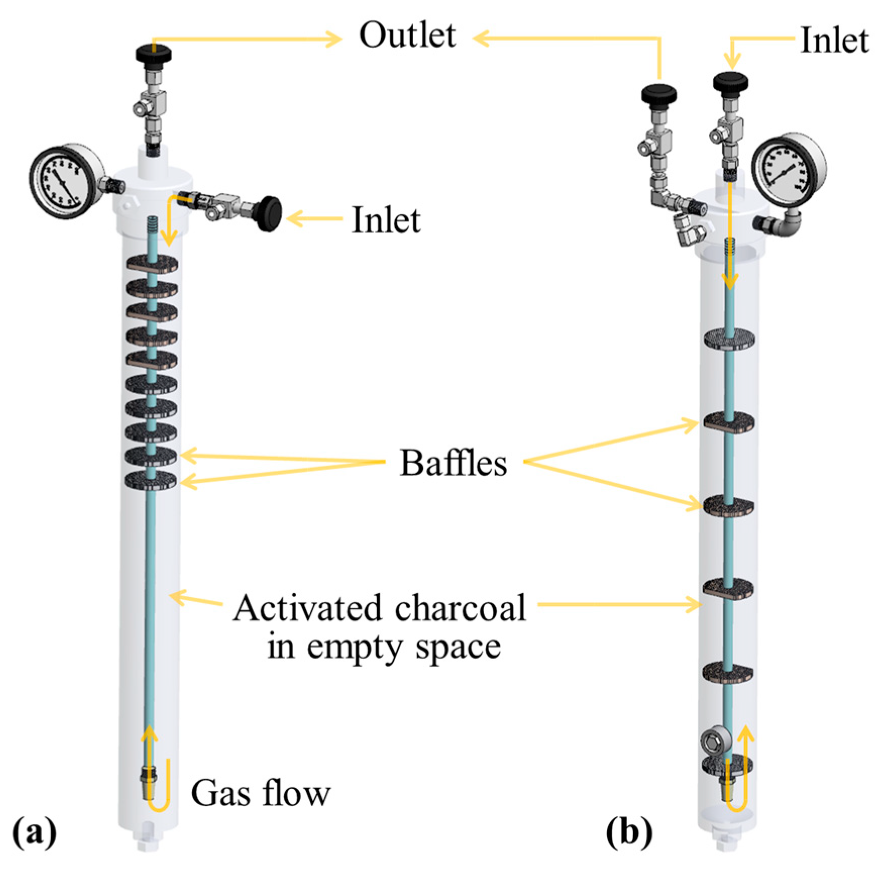
2.2.1. Impurity Removal System

An air compressor, heat exchanger, and hollow fiber membrane module were used to remove impurities in the air sample, as shown in Figure 2. First, the pressure of the sampled air was increased to 7 bar using the air compressor, and the temperature was lowered using the heat exchanger to condense and remove moisture above the saturated vapor. The compressed air was then passed through the hollow fiber membrane, and the remaining CO2 and H2O were removed according to the difference in their molecular sizes.
The hollow fiber membrane is a cylindrical membrane that selectively transports molecules in a radial direction. The molecule size is defined as the kinetic diameter of an atom or molecule without considering the size of its electron shell. The impurity removal principle using a hollow fiber membrane is illustrated in Figure 3.
As the mixed feed gas flowed through the hollow fiber membrane under increasing pressure, small molecules were expelled through the wall of the hollow fiber, whereas large molecules flowed in the hollow direction without permeating through the walls. Hollow fiber membranes are made of polysulfone, which is widely used as a membrane material because of its high mechanical strength, high thermal stability, and high chemical stability [14]. Gas separation using polymer membranes has already achieved significant success in commercial production since the late 1970s [15]. However, compared to polymer membranes, hollow fiber membranes have a structure that allows a higher surface-area-to-volume ratio, a more compact large filtration area into a small footprint, and operation at lower pressures.
We used hollow fiber membranes with internal and external diameters of 250 and 400 μm, respectively. The membranes were placed in a long cylindrical case with a diameter of 43 mm and length of 550 mm to build a module that removes CO2 and H2O from the air samples. Impurities such as H2O, CO2, H2, and O2, which have moderately small molecular kinetic diameters of 265, 330, 289, and 346 pm, respectively, permeated through the hollow fiber membrane wall. In contrast, Xe, Kr, and N2, which have large molecular kinetic diameters of 396, 360, and 364 pm, respectively, were retained in the hollow direction. This method can be used to achieve a constant removal efficiency without compromising performance during the removal process, unlike the conventional impurity removal method using soda lime and silica gel.
In addition, an automatic dried N2 generator that sprays dry N2 onto the surface of the hollow fiber membrane was constructed to prevent H2O condensation on the module surface, thereby maintaining a high impurity removal efficiency.

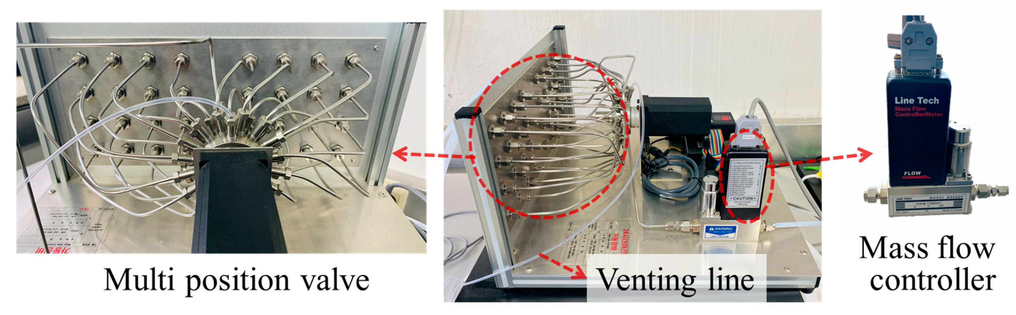
2.2.2. Automated Sample Distribution System

We designed an automated sample distribution system that continuously collects multiple adsorption modules using an MPV. A 16-channel MPV was used so that the impurity-removed air entered the MPV inlet and was delivered to one of the 16 channels as an outlet. The flow rate was controlled using a mass flow controller (MFC) with a maximum flow rate of 15 L min−1. Through this, gas can be collected by the desired adsorption module at a set flow rate and time. Figure 4 shows an automated sample distribution system that can continuously operate up to 16 adsorption modules in a single cycle.

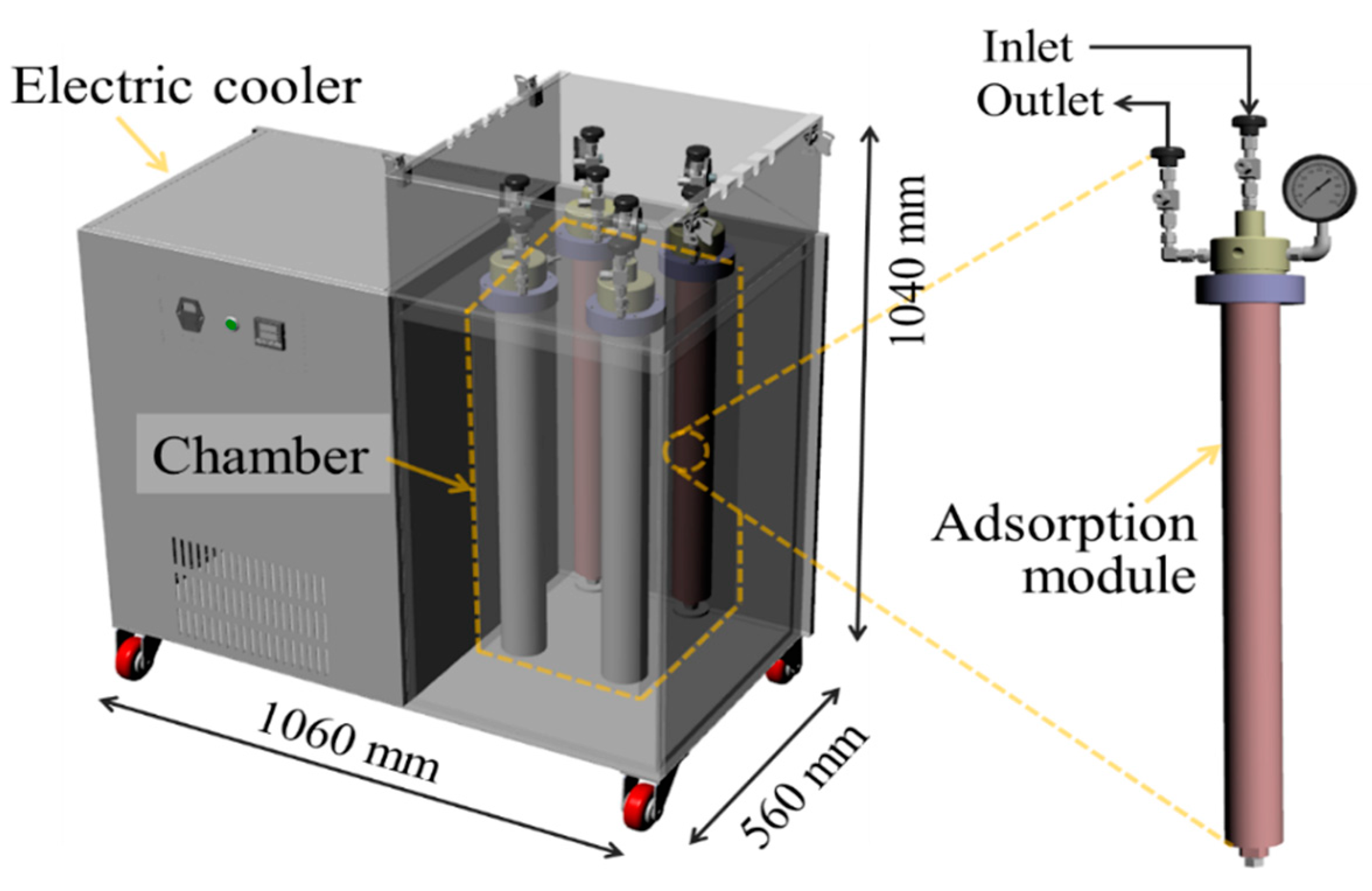
2.2.3. Adsorption Module

After passing through the MPV, the sampled gas was transferred to the inlet of the redesigned adsorption module. As shown in Figure 5a, conventional adsorption modules were designed such that the air sample is cooled through a baffle located at the top of the module and passed through the activated charcoal filled in the space at the bottom. The remaining H2O is condensed under cryogenic conditions in the upper space of the adsorption module where the baffles are located. It is necessary to remove this H2O before desorbing the Kr because H2O interferes with the adsorption of Kr on the activated carbon. Conversely, because the proposed system uses a hollow fiber membrane with superior water removal performance compared with conventional silica gel, the adsorption module does not require space for H2O removal; therefore, this space was filled with activated charcoal.
Thus, the redesigned module can contain up to 430 g of activated charcoal, which is more than twice the existing amount (200 g). This compensates for the disadvantages of electric cooling, which has a lower adsorption efficiency because of its higher temperature compared with that of LN2 cooling. As shown in Figure 5b, the sampled air enters the tube of the redesigned adsorption module, moves to the bottom, and passes through the baffles evenly located inside. The baffles cool the air, which is then passed through the activated charcoal and discharged from the outlet at the top. After the air sample passes through the adsorption modules, the air is discharged through the venting line of the MPV.

2.2.4. Electric Cooler

The air sample collected by the automated sample distribution system was transferred to an adsorption module filled with activated charcoal for Kr sampling. The existing cryogenic capture method has a limitation in that LN2 must be periodically replenished to maintain its capture performance. Hence, we designed an automated low-temperature capture system that uses an electric cooler instead of LN2 to improve the maintenance and repair of the cooling system. The electric cooler lowers the temperature of the cooling chamber where the adsorption modules are placed via vapor-compression refrigeration using compression, condensation, expansion, and evaporation. In addition, the water-cooling method was applied by filling the chamber with ethanol (vapor pressure 5.95 kPa at 20 °C) for increased cooling efficiency. The dimensions of the electric cooler are 1040 mm × 560 mm × 1060 mm, and it consists of a 43 L chamber with dimensions of 316 mm × 266 mm × 511 mm for the coolant, as shown in Figure 6. Four activated charcoal-packed adsorption modules can be mounted in the chamber for automatic sequential collection. A water level sensor was installed in the chamber to monitor the level of evaporation of the coolant, and a temperature sensor was installed to measure the cooling temperature. The maximum cooling temperature of the electric cooler was −90 °C. In the experiments, we applied a temperature of −80 °C to capture Kr in a stable low-temperature environment.

2.3. Performance Test

2.3.1. Impurity Removal Performance

To evaluate the performance of the developed impurity removal system, the H2O and CO2 concentrations in the air were measured before and after the impurity removal module was applied. The removal rates of H2O and CO2 were measured using a dew point analyzer (SADPmini, Alphamoisture, Bradford, England) and GC thermal conductivity detector (GC-TCD, Agilent, Santa Clara, CA, USA), respectively. We also measured the concentrations of H2O and CO2 in the surrounding air and air passing through the impurity removal module of BfS-IAR (soda lime, silica gel) in the same manner. The results were compared with those before and after passing through the impurity removal module.

2.3.2. Evaluation of Low-Temperature Capture Performance

To evaluate the capture performance of the developed electric cooler, sampling experiments were performed using standard gases with various Kr concentrations and volumes, and the amount of captured Kr and its capture efficiency were compared in each case. The Kr concentrations of the standard gases were 5, 10, and 100 ppm. The adsorption modules were pre-mounted in an electric cooler set to −80 °C at least 3 h before gas sampling so that the gas would be collected at a sufficiently low temperature. The gas is then transferred through the MPV to the adsorption modules mounted on the electric cooler at a sampling flow rate of 2 L/min. After sampling by the low-temperature electric cooler, the adsorption modules with a closed inlet and outlet were placed at room temperature for over 3 h so that some of the N2 in the air components could be desorbed from the adsorption module and released. The adsorption modules were then moved to the electric heating equipment and heated to a temperature of 300 °C so that the captured Kr could be desorbed. The desorbed gas was transferred into a vacuumed aluminum mini-can with a volume of 1 L at a constant flow rate using an MFC. The set flow rate of the MFC was 0.5 and 0.2 L/min, and the volume (Vminican, [L]) of the gas transferred to a mini-can (1 L gas canister) was calculated by measuring the transfer times T1 and T2 at each set flow rate using Equation (1).
V m i n i c a n = 0.5   [ L / min ] × T 1 [ min ] + 0.2   [ L / min ] × T 2 [ min ]
The amount of the sampled Kr and N2 in the mini-can be quantitatively analyzed using GC. The amount of Kr absorbed by the module was determined by calculating the volume of gas in the mini-can. Based on this, the Kr collection efficiency (Kreff, [%]) was calculated using the volume of desorbed gas transferred into the mini-can (Vminican), and the concentration of Kr (KrGC, [μL/L = ppm]) was measured using the GC.
K r e f f   [ % ] = V m i n i c a n   [ L ] × K r G C   [ μ L / L ] K r s a m p l e [ μ L ] × 100
where Krsample [μL] is the amount of Kr in the gas used in the experiment, which is obtained by multiplying the Kr concentration [ppm] of the standard gas by the volume [L] of the gas supplied to the adsorption module.
For GC, He was used as the carrier gas, and the TCD temperature was set at 200 °C. The sampled gas was injected into a 1 mL GC sample loop at a flow rate of 100 mL/min. Because the movement speed of gases differs depending on the interaction with the molecular sieve column (9ft, 1/8, Molsieve 5A), a difference in the retention time (RT) was observed in the column. The smaller the difference between the oven temperature and the boiling point of the gas, the faster the desorption. When the oven temperature is 60 °C, the peaks of N2 and Kr overlap with those of the gases transferred to the mini-can because of their similar RTs. Therefore, it was challenging to quantitatively evaluate the Kr concentration by measuring the Kr peak area. Hence, experiments were conducted to change the RT of the gas peak by lowering the oven temperature and separating the N2 and Kr peaks.

2.3.3. Evaluation of Air Capture Performance Using Automated Sampling System

Ambient air capture experiments were conducted to evaluate the performance of the developed impurity removal system using a hollow fiber membrane and an automated sample distribution system with a low-temperature electric cooler. Ambient air (1000 L) was collected at a flow rate of 2 L min−1. Similar to the previous experiments, the adsorption modules were mounted in an electric cooler set at −80 °C 3 h prior to sampling to allow air sampling at a sufficiently low temperature. After ambient air sampling, the adsorption modules were desorbed in the same manner as described in Section 2.2.2. The collected gas was then transferred into a mini-can. The Kr concentration of the ambient air sampled in the mini-can was analyzed using the detection part of the BfS-IAR system at the Korea Institute of Nuclear Safety (KINS), which is routinely applied for the quantification of 85Kr in ambient air. The BfS-IAR is a manual system used to measure the atmospheric activity concentrations of 85Kr and 133Xe, as mentioned in Section 1. The Kr recovery rate from sampling to radioactivity detection was evaluated, and the activity level of 85Kr was determined.

3. Results and Discussion

3.1. Impurity Removal Performance Evaluation

An impurity removal performance test using the hollow fiber membrane module was conducted prior to the gas-capture process. The CO2 and H2O removal efficiencies were compared using the impurity removal module of BfS-IAR. Table 1 shows the H2O and CO2 removal efficiencies of BfS-IAR and the hollow fiber membrane module from the collected air during the day at a flow rate of 7 L min−1 for each system.
At a temperature of 25 °C and a relative humidity of 45%, the H2O concentration in the air was 14,000 ppm, whereas the CO2 concentration was 1100 ppm. After removing the impurities using the developed hollow fiber membrane module, the H2O and CO2 concentrations in the air were 34.3–35.0 and 8.91 ± 0.9 ppm, respectively. In other words, the H2O removal efficiency was approximately 99.8%, which is higher than that for BfS-IAR (81.5%); therefore, the developed removal system does not require an additional procedure for the removal of H2O, which is essential for BfS-IAR. The CO2 removal efficiency was approximately 99.2%, which is similar to that for BfS-IAR. This hollow fiber membrane module enabled air sampling system automation with favorable impurity removal performance by removing only CO2 and H2O without the loss of Kr for collection and analysis.

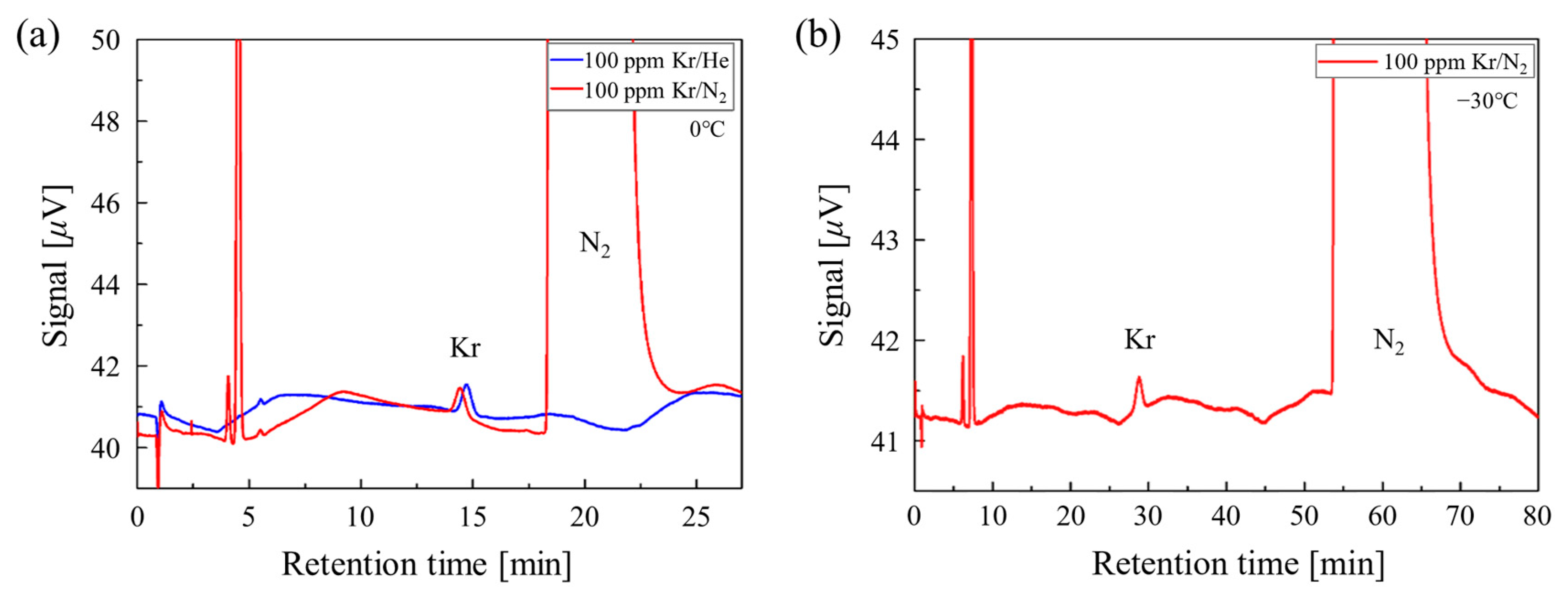
3.2. Quantification of Kr from N2 Using GC

Figure 7 shows the standard Kr gas spectrum at different GC oven temperatures. At an oven temperature of 0 °C, the RT of the Kr peak was approximately 14 min, and N2 was detected after 16 min. Interestingly, the vapor pressure of the gas components decreased with decreasing oven temperature; therefore, it was expected that the peak of N2 would be separated from that of Kr. The Kr peak was detected at the same RT, at a concentration of 100 ppm Kr standard gas balanced with He or N2, as shown in Figure 7a. At an oven temperature of −30 °C, the Kr and N2 peaks appeared at 28 and 50 min, respectively, improving the resolution of the Kr and N2 peaks, as shown in Figure 7b. In the developed sampling system, N2 was not effectively removed from Kr, indicating that the quantification of Kr under the normal temperature condition (30–40 °C) of the oven is not easy. At an oven temperature of 0 °C, the Kr and N2 peaks were separated, which was sufficient for quantitative evaluation. The experimental results were subsequently analyzed by applying the corresponding conditions in Section 2.3.2.

3.3. Analysis of Low-Temperature Capture Performance

To evaluate the low-temperature adsorption performance using an electric cooler, 100, 200, and 500 L of Kr standard gas at a concentration of 100 ppm were collected at a constant flow rate of 2 L min−1. We used N2-balanced Kr standard gas instead of a hollow fiber membrane module impurity removal system to estimate the low-temperature capture performance only. In addition, to ensure sufficient Kr sampling, sampling experiments were performed on 500 and 1000 L of Kr gas at concentrations of 10 and 5 ppm, respectively. The gas collection volume varied from 100 to 1000 L. After the gas was sampled by the adsorption module at a set volume, it was transferred to a mini-can for analysis.
Table 2 lists the amounts and recovery rates of Kr as a function of the Kr concentration and collected volume. Under the aforementioned experimental conditions, the amount of Kr tends to be almost constant according to the Kr concentration regardless of the collected gas volume, except at 100 L. This indicates that the amount of adsorbed Kr depends on the partial pressure of Kr in the gas sample. Notably, the Kr recovery rate is determined by the volume of the collected gas.
Figure 8 shows Kr recovery as a function of the collected gas volume cooled at −80 °C. This demonstrates that the Kr recovery rate is determined by the amount of gas collected in the adsorption module, regardless of the Kr concentration in the standard gas. Under the same cooling conditions, average Kr recovery rates of approximately 70, 58, 25, and 12% were obtained when 100, 200, 500, and 1000 L of the sample gas were collected, respectively. Interestingly, the Kr recovery rate decreased with increasing amounts of the collected gas. Therefore, the expected recovery rate of Kr from 1000 L of ambient air is approximately 12%. This is because activated charcoal does not selectively adsorb gases; hence, the amount of Kr adsorbed is affected by the N2 contained in the standard gas.

3.4. Determination of 85Kr Activity Concentration in Ambient Air

To evaluate the Kr capture performance of the developed system, sampling experiments using 1000 L of ambient air were performed using a hollow fiber membrane module impurity removal system and a low-temperature capture system using an electric cooler. As described in Section 2.2.1, CO2 and H2O were removed from the sampled air and transferred into the desired adsorption modules at a constant flow rate of 2 L min−1 through the MPV. The absorbed gas of the module was desorbed and transferred into a mini-can. As the concentration of Kr in the atmosphere was too low to be quantified by our GC system, we applied the processing and quantification parts of the BfS-IAR detection system for Kr detection in cooperation with KINS. Table 3 shows that the obtained radioactive Kr concentrations ranged from 1.15 to 1.76 Bq/m3, which is similar to the Northern Hemisphere average concentration of 1.5 Bq/m3. In addition, an average recovery rate of 7.8% (n = 5) was obtained from the calculation by applying 1.15 ppm, which is a stable Kr concentration in the Northern Hemisphere. However, because the amount of Kr obtained from 1000 L of ambient air was considerably small, the uncertainty of the Kr concentration measured using the BfS-IAR system increased, and the relative deviation was approximately 26%, indicating low reproducibility. It is estimated that the gas sampling temperature of −80 °C is feasible for Kr adsorption but insufficient for the reliable analysis of 85Kr.
This is an intermediate study for developing an automated Kr analysis system. While the use of the impurity removal system and the automated sample distribution system in this study proved a highly effective method, the adsorption system using the electric cooler requires further modifications to improve the Kr recovery rate. The initial experimental results demonstrated the applicability of the developed system as the sampling parts of the BfS-IAR system. It is anticipated that the developed automated sampling system can be integrated into the current BfS-IAR system. Regarding the Kr recovery rate, which is lower than the BfS-IAR method, the developed low-temperature capture system using the electric cooler can be further improved by applying a lower temperature or increasing the volume of activated charcoal in the adsorption module.

4. Conclusions

In this study, we developed an automatic Kr sampling system to overcome the limitations of the conventional impurity removal and Kr adsorption systems. We designed and developed this system using a hollow fiber membrane, an automated sample distribution system using an MPV, and a low-temperature capture system using an electric cooler. The developed system was tested by sampling ambient air from the laboratory under realistic conditions. It was found that the automated Kr sampling system achieved radioactive Kr concentrations ranging from 1.15 to 1.76 Bq/m3 at an average recovery rate of 7.8% from an air sample of 1000 L collected over 8 h 20 m at a flow rate of 2 L min−1. We believe that our study provides the basis for the development of a fully automated sampling and analysis system for continuous and remote Kr monitoring.

Author Contributions

Conceptualization, H.K. and M.J.; methodology, H.C. and H.K.; validation, W.L., M.J. and J.-M.L.; data curation, H.C. and H.K.; writing—original draft preparation, H.C.; writing—review and editing, H.K.; visualization, H.C.; funding acquisition, M.J. All authors have read and agreed to the published version of the manuscript.

Funding

This work was supported by the Nuclear Safety Research Program through the Korea Foundation Of Nuclear Safety (KoFONS) using financial resources granted by the Nuclear Safety and Security Commission (NSSC) of the Republic of Korea (No. 2203030-0120-SB110).

Institutional Review Board Statement

Not applicable.

Informed Consent Statement

Not applicable.

Data Availability Statement

Not applicable.

Acknowledgments

The authors would like to thank J.H. Park from KINS (Korea Institution of Nuclear Safety) for analyzing the 85Kr using the BfS-IAR method.

Conflicts of Interest

The authors declare no conflict of interest.

References

  1. Janssens, A.; Buysse, J.; Cottens, E. The Measurement of Low-Level Atmospheric Krypton-85. Nucl. Instrum. Methods Phys. Res. A 1985, 234, 335–343. [Google Scholar] [CrossRef]
  2. Schlosser, C.; Bollhöfer, A.; Schmid, S.; Krais, R.; Bieringer, J.; Konrad, M. Analysis of Radioxenon and Krypton-85 at the BfS Noble Gas Laboratory. Appl. Radiat. Isot. 2017, 126, 16–19. [Google Scholar] [CrossRef] [PubMed]
  3. Winger, K.; Feichter, J.; Kalinowski, M.B.; Sartorius, H.; Schlosser, C. A New Compilation of the Atmospheric 85krypton Inventories from 1945 to 2000 and Its Evaluation in a Global Transport Model. J. Environ. Radioact. 2005, 80, 183–215. [Google Scholar] [CrossRef] [PubMed]
  4. Bollhöfer, A.; Schlosser, C.; Schmid, S.; Konrad, M.; Purtschert, R.; Krais, R. Half a Century of Krypton-85 Activity Concentration Measured in Air over Central Europe: Trends and Relevance for Dating Young Groundwater. J. Environ. Radioact. 2019, 205–206, 7–16. [Google Scholar] [CrossRef] [PubMed]
  5. Yokochi, R.; Heraty, L.J.; Sturchio, N.C. Method for Purification of Krypton from Environmental Samples for Analysis of Radiokrypton Isotopes. Anal. Chem. 2008, 80, 8688–8693. [Google Scholar] [CrossRef] [PubMed]
  6. Saey, P.R.J. Ultra-Low-Level Measurements of Argon, Krypton and Radio Xenon for Treaty Verification Purposes. ESARDA Bull. 2007, 36, 42–56. [Google Scholar]
  7. Tu, L.Y.; Yang, G.M.; Cheng, C.F.; Liu, G.L.; Zhang, X.Y.; Hu, S.M. Analysis of Krypton-85 and Krypton-81 in a Few Liters of Air. Anal. Chem. 2014, 86, 4002–4007. [Google Scholar] [CrossRef] [PubMed]
  8. Avrahamov, N.; Yechieli, Y.; Purtschert, R.; Levy, Y.; Sültenfuß, J.; Vergnaud, V.; Burg, A. Characterization of a Carbonate Karstic Aquifer Flow System Using Multiple Radioactive Noble Gases (3H-3He, 85Kr, 39Ar) and 14C as Environmental Tracers. Geochim. Cosmochim. Acta 2018, 242, 213–232. [Google Scholar] [CrossRef]
  9. Kagabu, M.; Matsunaga, M.; Ide, K.; Momoshima, N.; Shimada, J. Groundwater Age Determination Using 85Kr and Multiple Age Tracers (SF6, CFCs, and 3H) to Elucidate Regional Groundwater Flow Systems. J. Hydrol. Reg. Stud. 2017, 12, 165–180. [Google Scholar] [CrossRef]
  10. Stockburger, H.; Sartorius, H. Messung Der Krypton-85-Und Xenon-133-Aktivität Der Atmosphärischen Luft/A Method for Measurement of the Krypton-85 and Xenon-133-Content in the Atmosphere. Z. Naturforsch. A 1977, 32, 1249–1253. [Google Scholar] [CrossRef]
  11. Chen, C.Y.; Li, Y.M.; Bailey, K.; O’Connor, T.P.; Young, L.; Lu, Z.T. Ultrasensitive Isotope Trace Analyses with a Magneto-Optical Trap. Science 1999, 286, 1139–1141. [Google Scholar] [CrossRef] [PubMed] [Green Version]
  12. Zappala, J.C.; Bailey, K.; Mueller, P.; O’Connor, T.P.; Purtschert, R. Rapid Processing of 85 Kr/Kr Ratios Using Atom Trap Trace Analysis. Water Resour. Res. 2017, 53, 2553–2558. [Google Scholar] [CrossRef] [Green Version]
  13. Igarashi, Y.; Aoyama, M.; Nemoto, K.; Hirose, K.; Miyao, T.; Fushimi, K.; Suzuki, M.; Yasui, S.; Asai, Y.; Aoki, I.; et al. 85Kr Measurement System for Continuous Monitoring at the Meteorological Research Institute, Japan. J. Environ. Monit. 2001, 3, 688–696. [Google Scholar] [CrossRef] [PubMed]
  14. Ismail, A.F.; Mansourizadeh, A. A Comparative Study on the Structure and Performance of Porous Polyvinylidene Fluoride and Polysulfone Hollow Fiber Membranes for CO2 Absorption. J. Membr. Sci. 2010, 365, 319–328. [Google Scholar] [CrossRef]
  15. Wang, D.; Teo, W.K.; Li, K. Preparation and Characterization of High-Flux Polysulfone Hollow Fibre Gas Separation Membranes. J. Membr. Sci. 2002, 204, 247–256. [Google Scholar] [CrossRef]
Figure 1. Schematics of the sampling methods for the (a) conventional and (b) proposed systems.
Atmosphere 14 01103 g001
Figure 2. Experimental setup of the impurity removal system.
Atmosphere 14 01103 g002
Figure 3. Schematic of the gas impurity removal principle using a hollow fiber membrane.
Atmosphere 14 01103 g003
Figure 4. Automated sample distribution system with the 16-channel MPV and MFC module.
Atmosphere 14 01103 g004
Figure 5. Schematic of the (a) existing adsorption module and (b) redesigned adsorption module with the improved cooling method and amount of activated charcoal.
Atmosphere 14 01103 g005
Figure 6. Low-temperature capture system using an electric cooler (left) with the adsorption module (right).
Atmosphere 14 01103 g006
Figure 7. Example of GC spectrum of Kr standard gas obtained at oven temperatures of (a) 0 °C and (b) −30 °C.
Atmosphere 14 01103 g007
Figure 8. Kr recovery rate as a function of the sampling volume.
Atmosphere 14 01103 g008
Table 1. Comparison of the impurity removal efficiencies of the BfS-IAR and hollow fiber membrane module through measurements of impurity concentrations before and after application.
ConcentrationAmbient AirBfS-IARHollow Fiber Membrane
H2O [ppm]14,0002529–263834.3–35.0
H2O removal efficiency [%]-81.599.8
CO2 [ppm]11002.74 ± 0.38.91 ± 0.9
CO2 removal efficiency [%]-99.899.2
Replacement cycle-Soda lime: every 4–5 samples
Silica gel: every sample
1/year
Table 2. Experimental results for the low-temperature adsorption performance measured based on the amount of Kr collected and the recovery rate.
Kr concentration [ppm]Volume [L]Main-Cooler [°C]Recovery [%]Kr [mL]
100100−8075.97.6
100100−80646.4
100200−8056.711.3
100200−8059.711.9
100500−8025.412.7
100500−8024.612.3
101000−8012.81.3
10500−8026.21.3
51000−8011.80.6
Table 3. Experimental results of Kr concentration obtained from ambient air.
Sample #12345
85Kr [Bq/m3]1.151.51.231.631.76
Disclaimer/Publisher’s Note: The statements, opinions and data contained in all publications are solely those of the individual author(s) and contributor(s) and not of MDPI and/or the editor(s). MDPI and/or the editor(s) disclaim responsibility for any injury to people or property resulting from any ideas, methods, instructions or products referred to in the content.

