Article

Fog Density Evaluation by Combining Image Grayscale Entropy and Directional Entropy

College of Science, Beijing Forestry University, Beijing 100083, China
*
Authors to whom correspondence should be addressed.
Atmosphere 2023, 14(7), 1125; https://doi.org/10.3390/atmos14071125
Submission received: 30 May 2023 / Revised: 2 July 2023 / Accepted: 5 July 2023 / Published: 7 July 2023
(This article belongs to the Section Atmospheric Techniques, Instruments, and Modeling)

Abstract

:
The fog density level, as one of the indicators of weather conditions, will affect the management decisions of transportation management agencies. This paper proposes an image-based method to estimate fog density levels to improve the accuracy and efficiency of analyzing fine meteorological conditions and validating fog density predictions. The method involves two types of image entropy: a two-dimensional directional entropy derived from four-direction Sobel operators, and a combined entropy that integrates the image directional entropy and grayscale entropy. For evaluating the performance of the proposed method, an image test set and an image training set are constructed; and each image is labeled as heavy fog, moderate fog, light fog, or fog-free according to the fog density level of the image based on a user study. Using our method, the average accuracy rates of image fog level estimation were 77.27% and 79.39% on the training set using the five-fold cross-validation and the test set, respectively. Our experimental results demonstrate the effectiveness of the proposed combined entropy for image-based fog density level estimation.

1. Introduction

Fog density forecasting and early warning is a crucial meteorological indicator that helps minimize fog’s impact on traffic safety [1]. The image-based fog density estimation method is becoming a low-cost and convenient means of fog density analysis due to the availability of video surveillance. Real-world images can provide a good indication of current visibility information, which makes it possible to infer the fog density level based on the image. With the increasing use of autonomous driving and intelligent monitoring, obtaining foggy image data under different weather conditions and measurement locations has become more convenient. These foggy images provide reliable experimental data for image-based fog density estimation research. In addition to providing fog forecasting and early warning, fog density estimation can also be used in image-defogging applications [2,3]. However, more research still needs to be done on classifying images based on fog density levels. An automatic and efficient method for evaluating fog density based on images would benefit various applications, including transportation, surveillance, and environmental monitoring.
We in this paper propose a new method by combining grayscale entropy and directional entropy to evaluate fog density levels and improve foggy image classification. Image entropy is a valuable tool for evaluating the degree of disorder and information content in images. At the same time, fog density can directly affect image color and shape information acquisition. By measuring changes in both color and shape influenced by fog, the new image entropy method helps improve the accuracy of foggy image classification and fog density evaluation.

2. Related Work

The literature related to this study can be broadly classified into two categories: image entropy and fog density evaluation.

2.1. Image Entropy

Entropy has a broad spectrum of applications in image processing. Conventional techniques compute image entropy using a solitary index, usually by extracting a specific attribute from the image and transforming pixel-level attributes into probability distributions. Probability distributions can be attained by computing a histogram of pixel intensity and normalizing it. The entropy is ultimately defined based on this probability distribution. Classical one-dimensional image entropy includes fuzzy entropy [4,5], Kapur entropy [6], cross entropy [7,8], and Shannon entropy [9]. In addition to being applied to image segmentation or classification, image entropy has also been applied to image filtering and denoising [10,11]. There are relatively few studies on two-dimensional or multidimensional entropy. Jena et al. [12] proposed a multi-threshold segmentation algorithm with three-dimensional Tsallis entropy as an objective function. Robin et al. [13] combined two-dimensional grayscale entropy with other features to achieve the binary classification of normal and cirrhotic liver ultrasound images.
Shape entropy measures the amount of information associated with an image’s shape. Compared to grayscale entropy, it describes an image’s texture and shape characteristics more efficiently. Typical shape features include image edges, line directions, boundary features, curvature functions, centroid distances, and geometric parameters such as roundness, eccentricity, and principal axis direction. Extracting shape features is a crucial step in studying shape entropy. Typical shape entropies include curvature entropy based on curvature function, edge entropy based on edge features, and directional entropy based on line directions. Shape entropy is widely used in image processing, including, but not limited to fingerprint and palm print recognition, leaf vein recognition, and wood texture recognition.
Using edge or contour information from images to define shape entropy is an effective method. Louis Oddo [14] proposed the concept of global and local shape entropy by introducing curvature as a measure of boundary information and calculating the first-order global shape entropy of boundary curvature, and used it for the automatic extraction of building outlines in aerial images. Briguglio et al. [15] calculated shape entropy based on the difference in length, middle axis length, and minor axis length of the particles; and used them to estimate the sedimentation velocity of the particles. Anders et al. [16] referred to the entropy effect generated by the geometric structure of shape in the particle model system as shape entropy, and proved that shape entropy drives the phase behavior of anisotropic shape systems through directional entropy force. Zhu [17] used the length and the number of breakpoints of the coastline to define shape entropy, which was then used to describe changes in the shoreline of the Yangtze River estuary. Lee et al. [18] defined the branch length similarity entropy (BLS entropy) to quantify the self-similarity of shape to solve shape problems in image retrieval. Hossein et al. [19] defined shape entropy based on the transverse slope of the cross-section of the riverbank, and used it to predict the shape trend of the riverbank profiles and the free water surface in the channel. Lu et al. [20] constructed the quadratic curvature entropy based on the Markov process, using it as macroscopic shape information of the curve profile of the target product to evaluate whether the product form conforms to consumers’ aesthetic preferences. Additionally, Sziová et al. [21] adopted structural Rényi entropy, based on the entropy definition, as one of the indexes to deal with the problem of insufficient data in colonoscopic polyp images.
Researchers have recently utilized different methods, such as particle system motion analysis and image contour line analysis, to design shape entropy for different research purposes. Despite these advancements, research on image shape entropy is still relatively limited. Therefore, further research and development are necessary to improve the accuracy and applicability of image shape entropy.

2.2. Fog Density Estimation

Fog density is traditionally measured by sensors, but this method is expensive, has limited coverage, and requires professional operators. In recent years, due to the rapid development of computer vision technology and the widespread application of monitoring equipment, research on the use of images for fog density estimation has received significant attention [3,22].
One commonly used approach is to utilize the dark channel of an image to determine fog density. Wan et al. [23] proposed an unsupervised learning method based on a five-dimensional feature vector consisting of edge strength, discrete cosine transform (DCT) ratio, dark channel (DC) ratio, average local contrast, and average standard deviation, as well as Gaussian mixture model. This method can classify fog images into three categories: fog-free, foggy, and dense fog. Li et al. [24] developed a foggy image classification algorithm that uses a linear SVM classifier and a hybrid feature composed of the dark channel, wavelet features, and mean normalization. Jiang et al. [25] employed a proxy-based method to learn a refined optical depth PRG model and selected features related to fog density, such as the dark channel, saturation value, and chrominance, for fog density estimation and image defogging. Ju et al. [26] defined a fog density index model to guide image defogging. This model utilizes the positive correlation between fog density’s minimum and range values, and the dark channel.
In addition, some literature employs image features, such as global contrast, color saturation, and image gradient, to estimate fog density. For example, in reference [27], foggy images were analyzed by maximizing three features relevant to fog density, including image saturation, brightness, and clarity, when performing foggy image classification and recognition. Lou et al. [28] defined fog density by brightness, saturation, and flatness; and established a linear model of transmittance and fog density based on these features. Literature [29] mainly focused on evaluating the defogging effect, subjectively dividing the fog image dataset into three levels: light fog, moderate fog, and heavy fog; and then comparing and analyzing the defogging results. The selection of features used depends on the specific application scenario and the image content that is prone to be affected by fog.
The two methods close to our research objectives are FADE (fog aware density evaluator) [2,30,31] and SFDE (a simple fog density evaluator) [32]. FADE extracts 12 dimensional features, such as MSCN coefficient variance, contrast, brightness fog perception statistical features; and uses a Mahalanobis-like distance measure between multivariate Gaussian fitting to predict the fog density. SFDE establishes a linear combination of three fog-related statistical features, namely saturation, Weber contrast of haze, and variance of chrome, for fog density estimation. Both methods mainly utilize color features, while our method utilizes color features and shape features.
In this paper, we propose a new shape entropy based on the two-dimensional angle characteristics of the edge points in the image. This shape entropy is combined with the gray entropy to estimate the fog density level in images. Referring to China’s national haze warning levels, yellow, orange, and red, which are three foggy cases, our image-based fog density classification results consist of four levels: fog-free, light fog, moderate fog, and heavy fog. The following sections will detail our methods, experiments, and conclusions.

3. Proposed Method

In this section, we propose a method for estimating fog density in images using a combined entropy approach. Our method first uses the Sobel operator in four directions to extract two-dimensional angular features from each edge point. We then calculate the binary probability and directional entropy, and construct a new type of combined entropy that integrates the image directional entropy and grayscale entropy to evaluate fog density and classify the image. The algorithm flow is as follows:
  • Step 1. Convert the original image to grayscale and perform pseudo-edge detection;
  • Step 2. Calculate two-dimensional grayscale entropy and directional entropy using the pseudo-edge image;
  • Step 3. Define a piecewise function to construct the combined entropy based on the fog density discrimination capability of the two entropies;
  • Step 4. Conduct experiments on both synthetic and real fog image datasets to evaluate the fog density level recognition performance of the combined entropy.

3.1. Two-Dimensional Grayscale Entropy

To comprehensively describe the spatial characteristics of the grayscale distribution of an image, an additional feature quantity is introduced based on the one-dimensional (1D) entropy of the image ( H g r a y 1 ) to form a two-dimensional (2D) entropy. The image is converted into a grayscale image. If the gray value at pixel point i , j is x 1 , and the average gray value of its 8-neighborhood is x 2 , the probability of the occurrence of the binary tuple   x 1 , x 2 , represented as p x 1 , x 2 ,   can be calculated. Based on this probability, the 2D entropy is calculated as:
H g r a y 2 I = x 1 = 0 255 x 2 = 0 255 p x 1 , x 2 log 2 p x 1 , x 2 ,  
The image entropy of a color image, denoted as H R G B , can be directly defined as the sum of the grayscale entropy ( H g r a y 1 ) of the image in the red, green, and blue color channels; and its calculation formula is as follows:
H R G B I = C R , G , B x = 0 255 p C x log 2 p C x ,  
Three foggy images listed in the top-left of Figure 1 are used to illustrate the values of images with different fog densities. The fog density of these images decreases gradually from left to right and exhibits significant visual variation.
The calculation results of three methods, H g r a y 1 , H g r a y 2 , and H R G B , are shown on the right of Figure 1 as the line charts of three types of entropy for three foggy images with different fog densities. It is observed that H g r a y 2 has the widest range of 3.3091 (i.e.,   12.0194 8.7103 = 3.3091 ), while the other two entropies (i.e., H g r a y 1 and H R G B ) have significantly smaller ranges of 0.6168 and 0.5085 , respectively. A larger range indicates a more distinctive contrast, which effectively distinguishes the fog density. Therefore, the two-dimensional grayscale entropy H g r a y 2 is integrated into constructing our proposed combined entropy.

3.2. Two-Dimensional Directional Entropy

The shape features in image content can be reflected to some extent by the image edges. There are many methods for calculating image edges; and we here use the Sobel operator in four directions, including 0° horizontal, 90° vertical, 45° diagonal, and 135° anti-diagonal, to calculate the gradients. The horizontal gradient g x and vertical gradient g y are calculated as follows:
g x i , j = I i + 1 , j 1 + 2 × I i + 1 , j + I i + 1 , j + 1 I i 1 , j 1 2 × I i 1 , j I i 1 , j + 1
g y i , j = I i 1 , j 1 + 2 × I i , j 1 + I i + 1 , j 1 I i 1 , j + 1 2 × I i , j + 1 I i + 1 , j + 1
In Formulas (3) and (4), I i , j is the gray value at pixel point i , j in the edge image. The gradient magnitude M a g 1   and direction θ 1   of edge points   i , j are computed as:
M a g 1 i , j = g x i , j 2 + g y i , j 2 ,
θ 1 i , j = a t a n 2   g y i , j g x i , j × 180 ° π + 180 ° ,
Similarly, using 45° and 135° directional templates, compute another gradient direction θ 2 i , j . With the two direction values, we generate a two-dimensional random variable θ 1 i , j , θ 2 i , j , which represents the directional feature of the edge pixel   i , j in the image.
Then, the marginal directional angle values of   θ 1 and θ 2 are discretized by dividing interval 0 o ,   360 o into n subintervals of equal size, which are   360 ° l 1 / n ,   360 ° × l / n , l = 1 , 2 , , n . These subintervals are labeled in ascending order as 1 to   n . Generally, a larger n results in a greater difference in entropy values, providing better differentiation effects. However, higher n-values also increase the computational complexity since the number of binary tuples that require counting rises, leading to a surge in events within the probability space.
Finally, each angle value of   θ 1   and θ 2 is assigned a corresponding quantization value between 1 and n.
Θ k i , j = l , θ k 360 ° n l 1 ,   360 ° n × l ,   l = 1 , 2 , , n ,
In this way, each pixel is mapped to a certain angle group, forming a new two-dimensional discrete random variable Θ 1 i , j , Θ 2 i , j . The edge points on each direction group are counted, and the resulting edge direction histogram is used as the image’s shape feature. After normalization, a probability distribution is obtained for each direction interval, and this distribution is used to calculate the two-dimensional directional entropy H s o b e l 2 I .
H s o b e l 2 I = Θ 1 = 1 n Θ 2 = 1 n p Θ 1 , Θ 2 l o g 2 p Θ 1 , Θ 2 .
In the Formula (8), p Θ 1 , Θ 2 = f Θ 1 , Θ 2 / N e d g e   , which represents the probability of occurrence of the two-dimensional discrete variable, where   f Θ 1 , Θ 2 is the statistical frequency of   Θ 1 , Θ 2   for all edge points in the image I, and N e d g e   is the number of edge points.
To simplify the notation, we denote the probability p Θ 1 , Θ 2 as p m , where m = Θ 1 1 n + Θ 2 , and m varies between 1 and n 2 . The probability vector is represented as   P = p 1 , p 2 , p n 2 . We can rewrite Formula (8) as follows:
H s o b e l 2 I = m = 1 n 2 p m l o g p m = H s o b e l 2 P ,
where H s o b e l 2 P is the entropy function of the probability vector   P , another expression of H s o b e l 2 I . It has been proven that the constructed 2D directional entropy H s o b e l 2 I satisfies the four properties of information entropy: non-negativity, symmetry, extremum, and additivity.
If only the horizontal and vertical gradients are preserved, Equation (8) degenerates into a 1D directional entropy formula, that is
H E D H I = i = 1 n p Θ i l o g p Θ i  
So, the 2D directional entropy H s o b e l 2 I is an extension of 1D directional entropy.
We use three images in the top-left of Figure 1 again to illustrate the calculation results of H s o b e l 2 and H E D H . At first, three pseudo-edge images are generated using the Canny operator and shown in the third row of Figure 1. Let n = 72 . After calculating with Formulas (9) and (10), two line charts are shown in the right sub-figure of Figure 1, which uncovers the relationship between 1D direction entropy ( H E D H ) and 2D direction entropy ( H s o b e l 2 ) with respect to the fog density. It could be found that both methods effectively highlight the differences in fog density, with the range of H s o b e l 2 being 2.6177, and   H E D H being 0.9127.
Obviously, the range of H s o b e l 2   is significantly higher than   H E D H , indicating that the proposed H s o b e l 2   can better distinguish the fog density. Thus, it can be used as an appropriate index to distinguish fog density within images. However, the value of H s o b e l 2 ,   like grayscale entropy, is not solely affected by fog density, but also by the scene within the image.

3.3. The Combined Entropy

Figure 1 shows that H g r a y 2   in red line changes less at high fog density, but significantly at low fog density, while the H s o b e l 2 in the purple line has the opposite performance. To utilize the advantages of both 2D grayscale entropy and 2D directional entropy in fog density estimation, we construct a piecewise function:
H c o m = H g r a y 2   ,     H g r a y 2   > δ H s o b e l 2 ,     H g r a y 2   δ
In Formula (11), the threshold δ in the function is an experimental value. In subsequent experiments, we provide a method to determine its value.

3.4. Algorithm Evaluation Indexes

To assess the effectiveness of the classification model, we create a confusion matrix that compares the preset fog density labels (true labels) with the model’s predicted labels. Using this matrix, four metrics, including precision, recall, f1 value, and accuracy, are calculated to objectively evaluate the effectiveness of the fog density level classification model.
If we divide fog density into K levels, each level is given a corresponding label between 1 and K. The resulting confusion matrix is represented as:
C M = m i j K × K
In Formula (12), m i j represents the number of samples with preset label i and algorithmic estimated label j, where i , j = 1 , 2 , , K . The precision, recall, and score f 1 of each category are:
P r e c i s i o n j = m j j i = 1 K m i j  
R e c a l l i = m i i j = 1 K m i j
f 1 i = 2 × p r e c i s i o n i × r e c a l l i p r e c i s i o n i + r e c a l l i
The overall index of the classification model is calculated by taking the weighted average of all the indexes.
Furthermore, accuracy, the overall evaluating index of classification tasks, can be calculated using Formula (16), as
A c c u r a c y = i = 1 K m i i i = 1 K j = 1 K m i j

4. Experiments and Results

It is necessary to verify the effectiveness of the proposed method for foggy images under different scenes. The experimental process for this section is illustrated in Figure 2.

4.1. Datasets and Preprocessing

Three datasets, as the following three subsections, are used to verify our method and to analyze the fog density levels.

4.1.1. Color Hazy Image Database

The Color Hazy Image Database (CHIC, http://chic.u-bourgogne.fr/chicpage.php, accessed on 16 August 2022) is opened by El Khoury et al. [33,34].
This dataset comprises CHIC_Static_scenes and CHIC_Dynamic_scenes. In CHIC_Static_scenes, there are two indoor scenes, named Scene 1 and Scene 2, in a controlled environment. Each scene consists of 10 images with different fog densities, from heavy fog (Level 1) to haze-free (Level 10). Ten images consisting of Scene 2 are displayed in Figure 3. We use the resized images from Scene 1 and Scene 2, and the size of each image is 1800 × 1200 .

4.1.2. Haze Groups Training Set

Our experimental dataset, Haze groups, is divided into training and test sets. The training set includes 194 images that are randomly selected from three publicly available datasets, O-HAZE, Dense_Haze, and D-HAZY_DATASET, as well as an image website, Ooopic (https://www.ooopic.com, accessed on 29 September 2022).
O-HAZE (https://data.vision.ee.ethz.ch/cvl/ntire18//o-haze/, accessed on 23 September 2022) is initially released by [35] and employed in the dehazing challenge of the NTIRE 2018 CVPR workshop, which contains 45 different outdoor scenes composed of pairs of real hazy and corresponding haze-free images. The fog with foggy images is relatively light.
Dense_Haze [36,37] contains 33 pairs of real hazy and corresponding haze-free images of various outdoor scenes, which are characterized by dense and homogeneous hazy scenes (https://data.vision.ee.ethz.ch/cvl/ntire19//dense-haze/, accessed on 25 September 2022).
HAZY, initially released by [38], contains more than 1400 pairs of images with ground truth reference images and synthetic hazy images of the same scene (https://dial.uclouvain.be/pr/boreal/object/boreal:175854/datastream/, accessed on 23 September 2022).

4.1.3. Haze Groups Test Set

The test set includes 131 images with different fog density levels. Some of those images are also randomly selected from O-HAZE, Dense_Haze, D-HAZY_DATASET, and Ooopic website. Other images are from another publicly available dataset, Foggy Driving (https://people.ee.ethz.ch/~csakarid/SFSU_synthetic/, accessed on 21 June 2023), which is released by [39,40], mainly composed of foggy images of traffic roads. The test set does not intersect with the training set.

4.1.4. Preprocessing

Images in the test and training sets are classified into four groups: heavy fog, moderate fog, light fog, and fog-free, with a questionnaire. According to the user study results, the number of images in each class is listed in Table 1. In this table, “Total N” is the number of images in the corresponding image set.
We then applied Formula (17) to assign appropriate labels for each image.
L a b e l = 1 , h e a v y   f o g 2 , m o d e r a t e   f o g 3 , l i g h t   f o g 4 , f o g f r e e
For the sake of computational efficiency in engineering applications, we downsized all images in the dataset by reducing them to 50% of their original size while preserving their initial aspect ratios. Figure 4 shows some examples of images from different fog density groups.

4.2. Experimental Results

4.2.1. The Threshold of Combinatorial Entropy

To find the threshold δ of combinatorial entropy (Formula (11)), images in Scene 2 in the CHIC dataset, as shown in Figure 3, are used to calculate their 2D grayscale entropy (Formula (1)), and 2D directional entropy (Formula (9)). The calculated results are shown as two line charts in Figure 5.
From Figure 5, it can be concluded that both H g r a y 2   and H s o b e l 2   are effective in distinguishing the ten different levels of fog density. From the first image to the fifth one, the difference in directional entropy ( H s o b e l 2   ) is more significant, making it easier to distinguish fog density levels. Conversely, grayscale entropy ( H g r a y 2 ) shows a relatively flat change and is not as effective in distinguishing fog density levels as the directional entropy. On the other hand, from the fifth image to the tenth one, the slope of the grayscale entropy curve becomes a lot bigger, highlighting a more apparent change in grayscale entropy. The shape entropy, however, remains relatively stable, showing minimal changes. These observations suggest that directional entropy is more effective in distinguishing higher fog density levels, while grayscale entropy is more effective in situations with lower fog density.
The threshold δ in the function (11) can be determined based on the experimental results (Figure 5) obtained from Scene 2. Figure 5 shows that the grayscale entropy of images at different fog density levels varied significantly, while the difference in directional entropy was relatively small. Hence, it is more reasonable to use the grayscale entropy value as a threshold. In this paper, the threshold δ was determined as 7.3 based on the mean grayscale entropy values of the fourth ( H g r a y 2 = 6.8142 ) and fifth images ( H g r a y 2   = 7.8099 5).
By setting δ = 7.3 and using Formula (11), the experiment results on two data sets, Scene 1 and Scene 2, are displayed as line charts in Figure 6. The curves in the figure display the relationship between the 2D grayscale entropy H g r a y 2   , the 2D directional entropy H s o b e l 2 , and the combined entropy H c o m concerning fog density. Two sub-figures clearly demonstrate that the proposed combined entropy H c o m is more effective than the other entropies in distinguishing the ten levels of fog density in the view of the strictly monotone increasing and maximum level difference.

4.2.2. Training and Analysis
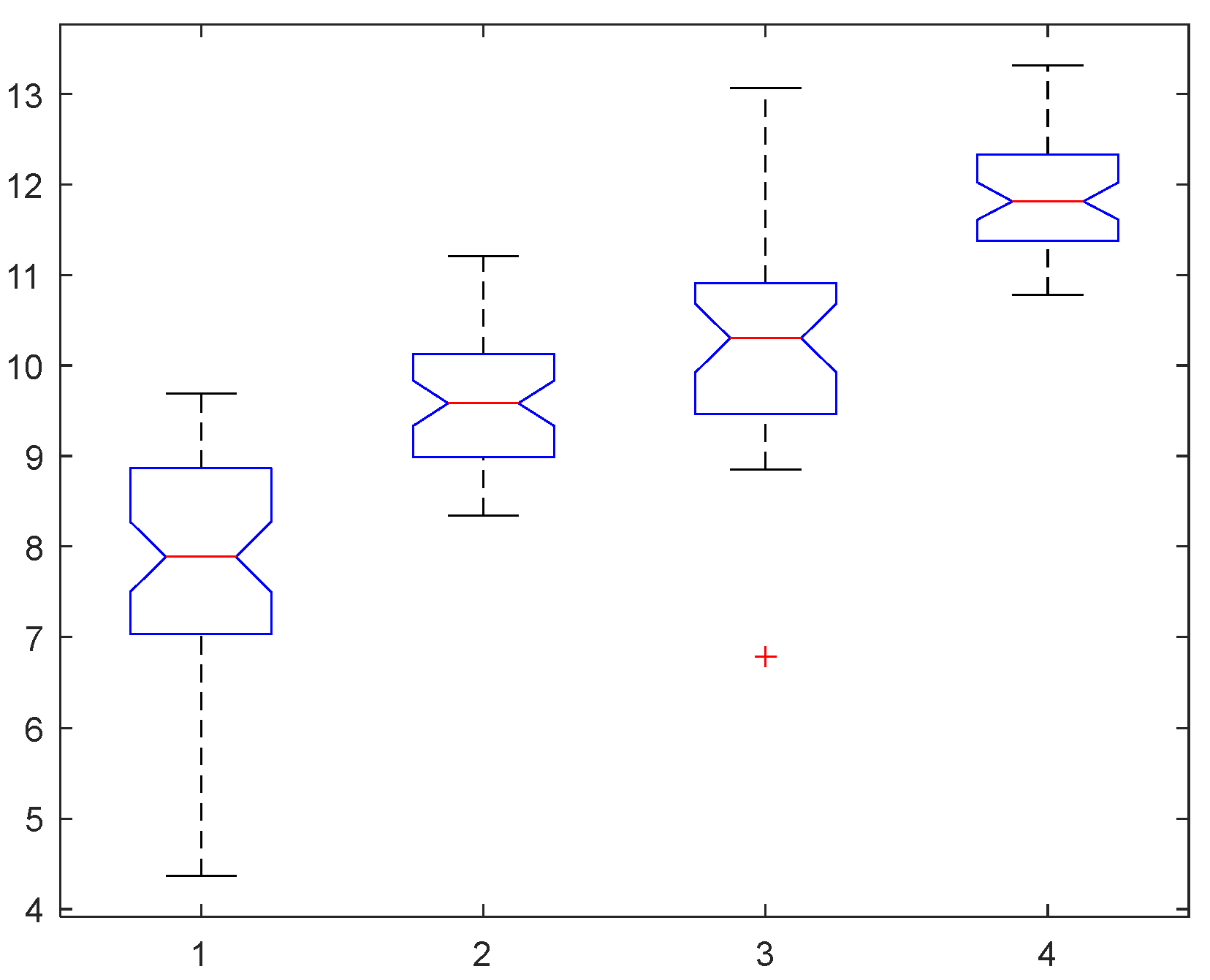
For classifying foggy images into four categories, heavy fog, moderate fog, light fog, and fog-free, using combination entropy, the training set of “Haze groups” is used to determine inter-class segmentation parameters.
First, the 2D grayscale entropy, 2D directional entropy, and combined entropy for all images in the training set are calculated. Next, all images were classified into four categories with respect to their fog density levels, which were estimated using the combined entropy value (Figure 7).
Figure 7 indicates that the curve of the combined entropy displays an overall increasing trend from thick fog to fog-free. The thick fog image exhibits a relatively low entropy value, with directional entropy playing a significant role. On the other hand, for images with lower fog density, grayscale entropy becomes the dominant contributing factor. This observation aligns with the findings in Section 3.3, where the fog-free image shows the highest entropy value. However, distinguishing between light and moderate fog data is challenging based on the graph. Next, we will classify the images based on their density levels, evaluated by their combined entropy values.
We first conduct a statistical analysis of the obtained entropy data. According to the pre-set labels (Section 4.1.4), the data are grouped and tested for normality. The test results showed that the p-value of the fog group is 0.0045, which is less than 0.05, indicating that the data in this group does not conform to the normal distribution. Therefore, the nonparametric Kruskal-Wallis (K-W) method [41] is selected for significance difference testing, with a significant level set to 0.05.
The null hypothesis H 0   is that there is no significant difference between these four sets of data, and the alternative hypothesis   H 1 is that that these four sets of data are significantly different.
The K-W test results show that the p-value is 6.3186 × 10 32 , less than the significance level of 0.05, which indicates a significant difference in the entropy results of the four groups.
Based on the results shown in Figure 7 and Figure 8, it can be observed that the third group exhibits outliers, and the distance between the upper or lower quartile values and the median is significant for both the first and third groups. These factors can potentially affect the normal distribution fitting effect. To eliminate the impact of outliers, we employ the 1sigma criterion (as the 3sigma criterion is not applicable in this experiment). Consequently, we obtained a final dataset that includes 37 images with heavy fog, 34 with moderate fog, 28 with light fog, and 33 without fog.
For the entropy data of the processed image group, we perform a new normality test. The results reveal that the p-values for the four groups of data are 0.2905, 0.3960, 0.2405, and 0.2521, all greater than 0.05; so, it can be considered that they all conform to normal distribution. Next, we conduct a homogeneity test for variance, and the result shows a p-value of 0.0002, which does not meet the homogeneity of variance condition. However, since the sample size of each dataset is small, the violation of the homogeneity of variance condition is temporarily overlooked. We will subsequently proceed with a one-factor ANOVA analysis.
Null hypothesis   H 0   : it is believed that the mean values of all four dataset are the same; alternative hypothesis   H 1 : it is believed that the mean values of the four datasets are different, and there are significant differences.
The p-value of the test result is 6.5322 × 10 56 , which is less than 0.05. Thus, the null hypothesis is rejected, and it is concluded that the mean values of the four sets of entropy values are significantly different. The boxplot shown in Figure 9 confirms the significant difference in the combined entropy of images with different fog density levels, which supports using this entropy value for fog density level evaluation.
In order to determine the fog density level based on the combined entropy, the first step is to determine the division thresholds ( δ 1 , δ 2 , δ 3 , and   δ 4 ) for the four categories using the training data. To achieve this, we perform a normal distribution fitting for each group of entropy data and present the fitting curves in Figure 10.
The threshold value for any two adjacent categories is determined by calculating the X value of their intersection within the fitted curve and the labeled adjacent curve. By utilizing these thresholds, it becomes feasible to construct a fog density level estimation model with the following structure:
L a b e l p r e d i c t = 1 , H c o m δ 1 2 , δ 1 < H c o m δ 2 3 , δ 2 < H c o m δ 3 4 , H c o m > δ 3
Utilize the five-fold cross-validation approach to train and fine-tune the model, enhancing its capacity for generalization. Table 2 shows the three thresholds obtained from five experiments along with the classification accuracy on both the training and testing sets using those thresholds. By averaging the thresholds obtained from the five experiments, the final thresholds are: δ 1 = 9.08, δ 2 = 9.8938, and δ 3 = 11.256. The fog density evaluation model with determined thresholds is:
L a b e l p r e d i c t = 1 , H c o m 9.08 2 , 9.08 < H c o m 9.8938 3 , 9.8938 < H c o m 11.256 4 , H c o m > 11.256
Based on the calculation results of the above model, all images in the dataset have been assigned new fog density levels, as depicted in Figure 11. The red dots indicate the preset fog density labels, while the yellow dots show the predicted labels. It is apparent from Figure 11 that the training performance is optimal for the set of clear images since they typically exhibit bright colors, clarity, brightness, and prominent edge details, leading to higher entropy values. Following this, the group of images with heavy fog has a better outcome because the images possess diminished edge information and low entropy values. On the other hand, the categorization effect for the groups containing light and medium fog images is less effective due to imprecise preset labels and difficulties in defining them. Additionally, the scene content of the images is obscured by thin fog, making it challenging to extract clear edge information.

4.3. Evaluation

To quantitatively evaluate the accuracy of our proposed method, we built the confusion matrix and compared our results to those estimated by FADE [2,30,31] and SFDE [32]. The three confusion matrices are displayed in Figure 12. The precision, recall, f1 value for each category, and classification accuracy are described in Table 3. In this table, “weighted-avg” is the weighted average.
From Table 3, it can be seen that among the three methods, our method attains the best performance according to all four indexes, precision, recall, f1, and overall accuracy; compared with the other two methods, SFDE and FADE, our method has improved overall accuracy by 64.7% and 41.4%, respectively. In addition, compared to the first category (heavy fog) and fourth category (fog-free), the three methods have relatively low recognition accuracy for the second and third categories, which may be a key point for constructing methods with higher accuracy in the future.

4.4. Experimental Results on Test Set

In this sub-section, the proposed method is validated on the test set and compared with FADE and SFDE. Three confusion matrices are built, similar to what has been conducted in Section 4.3. Then four metrics, precision, recall, f1 value, and accuracy, are calculated to objectively evaluate the three models’ effectiveness objectively.
The visual comparison of classification results can be seen in Figure 13. The classification performance of our model on the test is similar to that on the training set, with better performance in the heavy-fog and fog-free groups, and worse performance in the light-fog and moderate-fog groups. It is noteworthy that there is an increase in controversial images between the light-fog and fog-free groups because the images labeled as ‘3’ in fog-free groups mostly have monotonous colors, while some mist images are labeled as ‘4’, which are colorful and with complex scenes.
Then, the confusion matrices of the three methods assessed on the test set are displayed in Figure 14. Moreover, the precision, recall, f1 value for each category, and classification accuracy are described in Table 4.
As shown in Table 4, the proposed method obtains the best performance among the three methods, according to all four indexes, precision, recall, f1, and overall accuracy; compared with the other two methods, SFDE and FADE, our method has improved overall accuracy by 23.8% and 15.6%, respectively. Based on the classification results of the training and the test sets, our method performs the best among the three methods compared.

4.5. Discussion

When assessing the level of fog density in images, 2D grayscale entropy provides better results than 1D grayscale entropy. Additionally, 2D directional entropy based on the Sobel operator in four directions can better distinguish the level of fog density than 1D directional entropy based on the edge direction histogram. The results of 2D grayscale and 2D directional entropies on the same data set show they have different application ranges. As a result, a new quantitative indicator, combined entropy, is proposed.
Although the CHIC dataset’s combined entropy efficiently distinguishes ten fog density levels in both scenarios, the piecewise function thresholds need experimental derivation using diverse image sets with varying density levels within the same scene. We trained the threshold on scene 2 of the CHIC dataset, which yielded satisfactory outcomes when validated on scene 1. Nevertheless, this threshold has some restrictions due to the limited datasets of the same type. A more comprehensive dataset of the same type could lead to more precise thresholds.
Furthermore, the pre-labeling of fog density is based on the subjective visual perception of an individual, which can be influenced by personal observation and emotions. It is challenging to ensure the accuracy of the pre-labeling, potentially impacting the calculation of the final classification accuracy.
In summary, the proposed method has several limitations. On the one hand, the level of image fog density is labeled through the user study, which is a subjective way. A better approach is to build the relationship between the image entropy value and the measurable property of fog. The property can be measured through fixed-point scene sensing equipment and visibility measurements. On the other hand, the threshold δ in combined entropy is an experimental value. Although its value obtained in the experiment in this article showed a suitable partition, it still needs more experiments on a large number of datasets to test. Similarly, the thresholds of our classification model are also data-driven, and the generalizability of the proposed method still needs further verification.

5. Conclusions and Future Work

This study proposes a formula for calculating a two-dimensional directional entropy based on the four-direction Sobel gradient algorithm. Additionally, a combined entropy is constructed by merging the 2D grayscale entropy and 2D directional entropy to distinguish between various levels of fog density. This method was used to effectively differentiate between ten levels of fog density in images from the CHIC dataset. In the multi-scenario Haze-groups dataset, the study employed normal fitting to obtain related thresholds and utilized five-fold cross-validation for training the model. After obtaining the optimal threshold, the fog density was classified into four levels: heavy fog, medium fog, light fog, and fog-free. The four indicators calculated using the confusion matrix demonstrated that the classification accuracy rate of the combined entropy was larger than 77.2%, indicating effective differentiation of fog density levels.
There are only a few research results on image-based estimation of fog density, and there are still many related topics worth further research. For example, deep-learning methods have been widely applied in various fields recently, especially in image classification and restoration [42]. A natural extension is the image classification based on the image fog density level. Therefore, using deep-learning methods to estimate fog density after collecting labeled data [43] should be a promising research direction in the future. In addition to the directional entropy and combined entropy proposed in this paper, we can also extract other fog density-related features, such as brightness, saturation, dark channel, to form a multi-dimensional feature group, input the convolutional neural network encoder for better representation, and then use the classifier for training to judge the image fog concentration level. Selecting features, determining feature dimensions, and balancing classification accuracy and computational efficiency are all critical issues worth studying.

Author Contributions

Conceptualization, R.C., X.W. and H.L.; methodology, X.W. and H.L.; software, R.C. and H.L.; validation, R.C. and H.L.; formal analysis, R.C. and X.W.; investigation, R.C.; resources, R.C.; data curation, R.C.; writing—original draft preparation, R.C.; writing—review and editing, X.W.; visualization, R.C. and H.L.; supervision, X.W. and H.L.; project administration, H.L.; funding acquisition, X.W. All authors have read and agreed to the published version of the manuscript.

Funding

This research was funded by the NSFC, grant number 61571046.

Institutional Review Board Statement

Not applicable.

Informed Consent Statement

Not applicable.

Data Availability Statement

The data download links have been embedded in the location of the data introduction in the main text (Section 4.1).

Acknowledgments

We would like to sincerely thank the authors of the FADE and SFDE algorithms for sharing their code. The constructive comments from anonymous reviewers were also greatly appreciated.

Conflicts of Interest

The authors declare no conflict of interest.

References

  1. Bartokova, I.; Bott, A.; Bartok, J.; Gera, M. Fog Prediction for Road Traffic Safety in a Coastal Desert Region: Improvement of Nowcasting Skills by the Machine-Learning Approach. Bound. Layer Meteorol. 2015, 157, 501–516. [Google Scholar] [CrossRef]
  2. Choi, L.K.; You, J.; Bovik, A.C. Referenceless Prediction of Perceptual Fog Density and Perceptual Image Defogging. IEEE Trans. Image Process. 2015, 24, 3888–3901. [Google Scholar] [CrossRef] [PubMed]
  3. Guo, H.; Wang, X.; Li, H. Density Estimation of Fog in Image Based on Dark Channel Prior. Atmosphere 2022, 13, 710. [Google Scholar] [CrossRef]
  4. Li, G.; An, C.; Zhang, Y.; Tu, X.; Tan, M. Color Image Clustering Segmentation Based on Fuzzy Entropy and RPCL. J. Image Graph. 2005, 10, 1264–1268+1204. [Google Scholar] [CrossRef]
  5. Lhermitte, E.; Hilal, M.; Furlong, R.; O’Brien, V.; Humeau-Heurtier, A. Deep Learning and Entropy-Based Texture Features for Color Image Classification. Entropy 2022, 24, 1577. [Google Scholar] [CrossRef]
  6. Lang, C.; Jia, H. Kapur’s Entropy for Color Image Segmentation Based on a Hybrid Whale Optimization Algorithm. Entropy 2019, 21, 318. [Google Scholar] [CrossRef] [Green Version]
  7. Zhao, Y.; Zeng, L.; Wu, Q. Classification of Cervical Cells Based on Convolution Neural Network. Jisuanji Fuzhu Sheji Yu Tuxingxue Xuebao/J. Comput.-Aided Des. Comput. Graph. 2018, 30, 2049–2054. [Google Scholar] [CrossRef]
  8. Ni, K.; Zhai, M.; Wang, P. Scene Classification of Remote Sensing Images Based on Wavelet-Spatial High-Order Feature Aggregation Network. Guangxue Xuebao/Acta Opt. Sin. 2022, 42, 212–221. [Google Scholar] [CrossRef]
  9. Cassetti, J.; Delgadino, D.; Rey, A.; Frery, A.C. Entropy Estimators in SAR Image Classification. Entropy 2022, 24, 509. [Google Scholar] [CrossRef]
  10. Imani, M. Entropy/anisotropy/alpha based 3DGabor filter bank for PolSAR image classification. Geocarto Int. 2022, 37, 18491–18519. [Google Scholar] [CrossRef]
  11. Wang, Y.; Zhou, L.; Zhang, X. Spatio-temporal regularized shock-diffusion filtering with local entropy for restoration of degraded document images. Appl. Math. Comput. 2023, 439, 127618. [Google Scholar] [CrossRef]
  12. Jena, B.; Naik, M.K.; Panda, R.; Abraham, A. Maximum 3D Tsallis entropy based multilevel thresholding of brain MR image using attacking Manta Ray foraging optimization. Eng. Appl. Artif. Intell. 2021, 103, 104293. [Google Scholar] [CrossRef]
  13. Luo, B.; Wang, B.; Ni, S. Texture-Based Automatic classification of B-scan Liver Images. Pattern Recognit. Artif. Intell. 1995, 8, 76–81. [Google Scholar]
  14. Oddo, L.A. Global shape entropy: A mathematically tractable approach to building extraction in aerial imagery. In Proceedings of the 20th AIPR Workshop: Computer Vision Applications: Meeting the Challenges, McLean, VA, USA, 16–18 October 1991; pp. 91–101. [Google Scholar]
  15. Briguglio, A.; Hohenegger, J. How to react to shallow water hydrodynamics: The larger benthic foraminifera solution. Mar. Micropaleontol. 2011, 81, 63–76. [Google Scholar] [CrossRef] [Green Version]
  16. van Anders, G.; Klotsa, D.; Ahmed, N.K.; Engel, M.; Glotzer, S.C. Understanding shape entropy through local dense packing. Proc. Natl. Acad. Sci. USA 2014, 111, E4812–E4821. [Google Scholar] [CrossRef]
  17. Zhu, M.S.; Sun, T.; Shao, D.D. Impact of Land Reclamation on the Evolution of Shoreline Change and Nearshore Vegetation Distribution in Yangtze River Estuary. Wetlands 2016, 36, S11–S17. [Google Scholar] [CrossRef]
  18. Lee, S.-H.; Park, C.-M.; Choi, U. A New Measure to Characterize the Degree of Self-Similarity of a Shape and Its Applicability. Entropy 2020, 22, 1061. [Google Scholar] [CrossRef]
  19. Bonakdari, H.; Gholami, A.; Mosavi, A.; Kazemian-Kale-Kale, A.; Ebtehaj, I.; Azimi, A.H. A Novel Comprehensive Evaluation Method for Estimating the Bank Profile Shape and Dimensions of Stable Channels Using the Maximum Entropy Principle. Entropy 2020, 22, 1218. [Google Scholar] [CrossRef]
  20. Lu, P.; Hsiao, S.-W.; Wu, F. A Product Shape Design and Evaluation Model Based on Morphology Preference and Macroscopic Shape Information. Entropy 2021, 23, 639. [Google Scholar] [CrossRef]
  21. Sziova, B.; Nagy, S.; Fazekas, Z. Application of Structural Entropy and Spatial Filling Factor in Colonoscopy Image Classification. Entropy 2021, 23, 936. [Google Scholar] [CrossRef]
  22. Wen, L.-M.; Ju, Y.-F.; Yan, M.-D. Inspection of Fog Density for Traffic Image Based on Distribution Characteristics of Natural Statistics. Tien Tzu Hsueh Pao/Acta Electron. Sin. 2017, 45, 1888–1895. [Google Scholar] [CrossRef]
  23. Wan, J.; Qiu, Z.; Gao, H.; Jie, F.; Peng, Q. Classification of fog situations based on Gaussian mixture model. In Proceedings of the 36th Chinese Control Conference, CCC 2017, Dalian, China, 26–28 July 2017; pp. 10902–10906. [Google Scholar]
  24. Li, K.; Chen, H.; Zhang, S.; Wan, J. An SVM Based Technology for Haze Image Classification. Electron. Opt. Control 2017, 25, 37–41+47. [Google Scholar]
  25. Jiang, Y.; Sun, C.; Zhao, Y.; Yang, L. Fog Density Estimation and Image Defogging Based on Surrogate Modeling for Optical Depth. IEEE Trans. Image Process. 2017, 26, 3397–3409. [Google Scholar] [CrossRef] [PubMed]
  26. Ju, M.; Chen, C.; Liu, J.; Cheng, K.; Zhang, D. VRHI: Visibility restoration for hazy images using a haze density model. In Proceedings of the 2021 IEEE/CVF Conference on Computer Vision and Pattern Recognition Workshops, CVPRW 2021, Virtual, 19–25 June 2021; pp. 897–904. [Google Scholar]
  27. Ngo, D.; Lee, G.-D.; Kang, B. Haziness Degree Evaluator: A Knowledge-Driven Approach for Haze Density Estimation. Sensors 2021, 21, 3896. [Google Scholar] [CrossRef]
  28. Lou, W.; Li, Y.; Yang, G.; Chen, C.; Yang, H.; Yu, T. Integrating Haze Density Features for Fast Nighttime Image Dehazing. IEEE Access 2020, 8, 113318–113330. [Google Scholar] [CrossRef]
  29. Zhao, S.; Zhang, L.; Huang, S.; Shen, Y.; Zhao, S. Dehazing Evaluation: Real-World Benchmark Datasets, Criteria, and Baselines. IEEE Trans. Image Process. 2020, 29, 6947–6962. [Google Scholar] [CrossRef]
  30. Choi, L.K.; You, J.; Bovik, A.C. Referenceless perceptual fog density prediction model. In Proceedings of the Human Vision and Electronic Imaging XIX, San Francisco, CA, USA, 3–6 February 2014; p. 90140H. [Google Scholar] [CrossRef]
  31. Choi, L.K.; You, J.; Bovik, A.C. Referenceless perceptual image defogging. In Proceedings of the 2014 IEEE Southwest Symposium on Image Analysis and Interpretation, SSIAI 2014, San Diego, CA, USA, 6–8 April 2014; pp. 165–168. [Google Scholar]
  32. Ling, Z.; Gong, J.; Fan, G.; Lu, X. Optimal Transmission Estimation via Fog Density Perception for Efficient Single Image Defogging. IEEE Trans. Multimed. 2018, 20, 1699–1711. [Google Scholar] [CrossRef]
  33. El Khoury, J.; Thomas, J.-B.; Mansouri, A. A database with reference for image dehazing evaluation. J. Imaging Sci. Technol. 2018, 62, 10503. [Google Scholar] [CrossRef]
  34. El Khoury, J.; Thomas, J.-B.; Mansouri, A. A color image database for haze model and dehazing methods evaluation. In Proceedings of the 7th International Conference on Image and Signal Processing, ICISP 2016, Trois Rivieres, QC, Canada, 30 May–1 June 2016; pp. 109–117. [Google Scholar]
  35. Ancuti, C.O.; Ancuti, C.; Timofte, R.; De Vleeschouwer, C. O-HAZE: A dehazing benchmark with real hazy and haze-free outdoor images. In Proceedings of the 31st Meeting of the IEEE/CVF Conference on Computer Vision and Pattern Recognition Workshops, CVPRW 2018, Salt Lake City, UT, USA, 18–22 June 2018; pp. 867–875. [Google Scholar]
  36. Ancuti, C.O.; Ancuti, C.; Sbert, M.; Timofte, R. Dense-Haze: A Benchmark for Image Dehazing with Dense-Haze and Haze-Free Images. In Proceedings of the 26th IEEE International Conference on Image Processing, ICIP 2019, Taipei, Taiwan, 22–25 September 2019; pp. 1014–1018. [Google Scholar]
  37. Ancuti, C.O.; Ancuti, C.; Timofte, R.; Van Gool, L.; Zhang, L.; Yang, M.-H.; Guo, T.; Li, X.; Cherukuri, V.; Monga, V.; et al. NTIRE 2019 image dehazing challenge report. In Proceedings of the 32nd IEEE/CVF Conference on Computer Vision and Pattern Recognition Workshops, CVPRW 2019, Long Beach, CA, USA, 16–20 June 2019; pp. 2241–2253. [Google Scholar]
  38. Ancuti, C.; Ancuti, C.O.; De Vleeschouwer, C. D-HAZY: A dataset to evaluate quantitatively dehazing algorithms. In Proceedings of the 23rd IEEE International Conference on Image Processing, ICIP 2016, Phoenix, AZ, USA, 25–28 September 2016; pp. 2226–2230. [Google Scholar]
  39. Sakaridis, C.; Dai, D.; Van Gool, L. Semantic Foggy Scene Understanding with Synthetic Data. Int. J. Comput. Vis. 2018, 126, 973–992. [Google Scholar] [CrossRef] [Green Version]
  40. Cordts, M.; Omran, M.; Ramos, S.; Rehfeld, T.; Enzweiler, M.; Benenson, R.; Franke, U.; Roth, S.; Schiele, B. The Cityscapes Dataset for Semantic Urban Scene Understanding. In Proceedings of the 29th IEEE Conference on Computer Vision and Pattern Recognition, CVPR 2016, Las Vegas, NV, USA, 26 June–1 July 2016; pp. 3213–3223. [Google Scholar]
  41. Theodorsson-Norheim, E. Kruskal-Wallis Test: Basic Computer Program to Perform Nonparametric One-Way Analysis of Variance and Multiple Comparisons on Ranks of Several Independent Samples. Comput. Methods Programs Biomed. 1986, 23, 57–62. [Google Scholar] [CrossRef]
  42. Su, J.; Xu, B.; Yin, H. A survey of deep learning approaches to image restoration. Neurocomputing 2022, 487, 46–65. [Google Scholar] [CrossRef]
  43. Zhang, J.; Min, X.; Zhu, Y.; Zhai, G.; Zhou, J.; Yang, X.; Zhang, W. HazDesNet: An End-to-End Network for Haze Density Prediction. IEEE Trans. Intell. Transp. Syst. 2022, 23, 3087–3102. [Google Scholar] [CrossRef]
Figure 1. Comparison of five entropy values for images with varying levels of fog density. On the left, the first row shows three images with significantly different fog density. The corresponding grayscale images and pseudo-edge details are presented on the second and third rows, respectively. (d) is a comparison chart of the five entropy values of the three images (ac). H g r a y 1 , H g r a y 2 , H R G B , H E D H , and H s o b e l 2 refer to one-dimensional grayscale entropy, two-dimensional grayscale entropy, color image entropy, 1D directional entropy, and 2D directional entropy, respectively.
Atmosphere 14 01125 g001
Figure 2. Flowchart rof the experimrent.
Atmosphere 14 01125 g002
Figure 3. Ten images in different fog density levels in Scene 2.
Atmosphere 14 01125 g003
Figure 4. Several sample images from different fog density groups in Haze Groups constructed in this paper using multiple datasets.
Atmosphere 14 01125 g004
Figure 5. Comparison of the 2D grayscale entropy and the 2D directional entropy using images from Scene 2 in CHIC dataset. The numbers on the x-axis indicate that the image sequence number is consistent with the image sequence in Figure 3. The red dashed line represents δ 0 = 7.3 , which means the position where the curvature of the two lines changes significantly.
Atmosphere 14 01125 g005
Figure 6. Line charts of three image entropies calculated by three methods on images from Scene 1 and Scene 2. The thick line is the line chart of combined entropy proposed in this paper.
Atmosphere 14 01125 g006
Figure 7. Line charts of the 2D grayscale entropy   H g r a y 2 , 2D directional entropy H s o b e l 2 , and combined entropy H c o m   for images in training set. The blue line overlaps with the orange line with red square when H c o m > 7.3 . Otherwise, the blue line overlaps with the green one. Each entropy calculation result is divided into four segmented groups, corresponding to four different concentration levels of fog.
Atmosphere 14 01125 g007
Figure 8. Box plot of K-W test results of significant difference for the combined entropy. Four boxes from left to right are H c o m values of heavy fog, moderate fog, light fog, and fog-free group, respectively. The information contained in each box includes the upper or lower quartile values and the median.
Atmosphere 14 01125 g008
Figure 9. Box plot of single-factor variance analysis results for the combined entropy. The information contained in each box includes the mean values of the four sets of H c o m   entropy values.
Atmosphere 14 01125 g009
Figure 10. Normal fitting curve and intersection point using the five-fold cross-validation. Each sub-figure represents a cross-validation. Different color bars represent different image categories, i.e., images with different fog density levels.
Atmosphere 14 01125 g010
Figure 11. Analysis of classification accuracy of the training set.
Atmosphere 14 01125 g011
Figure 12. Heatmap of three confusion matrices constructed on the training set using three methods, respectively.
Atmosphere 14 01125 g012
Figure 13. Analysis of classification accuracy of test set.
Atmosphere 14 01125 g013
Figure 14. Heatmap of three confusion matrices constructed on the Test set using three methods, respectively.
Atmosphere 14 01125 g014
Table 1. The number of images in each class.
SetHeavy FogModerate FogLight FogFog-FreeTotal N
Training set55513652194
Test set38342435131
Table 2. Experimental results on the training set using five-fold cross-validation.
Index δ 1 δ 2 δ 3 Training AccuracyTesting Accuracy
19.1069.95211.20.80000.7692
29.029.77711.210.77360.6154
39.0369.91311.310.76420.8077
49.069.82911.30.72380.8519
59.1789.99811.260.83960.6538
Table 3. Accuracy comparison of fog density estimated on the training set by three methods.
SFDEFADEOur Method
LabelPrecisionRecallf1PrecisionRecallf1PrecisionRecallf1
10.58540.43640.50000.75560.61820.68000.82500.89190.8571
20.44120.30000.35710.39680.50000.44250.57580.55880.5672
30.25400.43240.32000.29170.37840.32940.68000.60710.6415
40.64290.69230.66670.86840.63460.73330.97061.00000.9851
weighted avg0.50040.40910.47350.60490.54640.56620.77640.77270.7787
Accuracy0.46910.54640.7727
Table 4. Accuracy comparison of fog density estimated on the test set by three methods.
SFDEFADEOur Method
LabelPrecisionRecallf1PrecisionRecallf1PrecisionRecallf1
10.64150.89470.74730.62710.97370.76290.85710.94740.9000
20.56520.38240.45610.57140.35290.43640.80770.61760.7000
30.40740.45830.43140.60000.50000.54550.58620.70830.6415
40.92860.74260.82540.93550.82860.87880.88240.85710.8696
weighted avg0.65550.64120.63470.69010.68700.66930.80140.79390.7926
Accuracy0.64120.68700.7939
Disclaimer/Publisher’s Note: The statements, opinions and data contained in all publications are solely those of the individual author(s) and contributor(s) and not of MDPI and/or the editor(s). MDPI and/or the editor(s) disclaim responsibility for any injury to people or property resulting from any ideas, methods, instructions or products referred to in the content.

