Article

Synthetic Wind Estimation for Small Fixed-Wing Drones

Environmental Sensing Observatory, Laboratory of Cryospheric Sciences (CRYOS), École Polytechnique Fédérale de Lausanne (EPFL), Route des Ronquos 86, 1950 Sion, Switzerland
*
Author to whom correspondence should be addressed.
Atmosphere 2024, 15(11), 1339; https://doi.org/10.3390/atmos15111339
Submission received: 27 September 2024 / Revised: 25 October 2024 / Accepted: 26 October 2024 / Published: 8 November 2024
(This article belongs to the Section Atmospheric Techniques, Instruments, and Modeling)

Abstract

:
Wind estimation is crucial for studying the atmospheric boundary layer. Traditional methods such as weather balloons offer limited in situ capabilities; besides an Air Data System (ADS) combined with inertial measurements and satellite positioning is required to estimate the wind on fixed-wing drones. As pressure probes are an important constituent of an ADS, they are susceptible to malfunctioning or failure due to blockages, thus affecting the capability of wind sensing and possibly the safety of the drone. This paper presents a novel approach, using low-fidelity aerodynamic models of drones to estimate wind synthetically. In our work, the aerodynamic model parameters are derived from post-processed flight data, in contrast to existing approaches that use expensive wind tunnel calibration for identifying the same. In sum, our method integrates aerodynamic force and moment models into a Vehicle Dynamic Model (VDM)-based navigation filter to yield a synthetic wind estimate without relying on an airspeed sensor. We validate our approach using two geometrically distinct drones, each characterized by a unique aerodynamic model and different quality of inertial sensors, altogether tested across several flights. Experimental results demonstrate that the proposed cross-platform method provides a synthetic wind velocity estimate, thus offering a practical backup to traditional techniques.

1. Introduction

Boundary-layer meteorology studies primarily focus on understanding the atmospheric processes in the layer of air in contact with the Earth’s surface. Wind is one of the critical entities that is required to understand these processes. It is also important to note that acquiring high-resolution spatial and temporal wind measurements is challenging given the constrained mobility of land-based sensors, logistical difficulties, and the environmental impact associated with deploying balloon-based sensors [1]. The technological boom in aerial robotics in the past few decades has inspired the use of drones (rotary/winged/hybrid) for many novel applications; meteorological research, with a particular focus on wind measurement, is one among many others. A comprehensive review of various methodologies for wind estimation using rotary drones, as described in [2], provides valuable insights. However, since our work is focused on fixed-wing drones (we motivate the benefits of such drones later in Section 4.2), most of our literature review emphasizes wind estimation techniques specifically tailored to fixed-wing platforms. For these drones, wind estimation is typically carried out through inexpensive sensors and powerful onboard computers. For instance, in [3], measurements from a single-hole pitot tube are fused with AHRS (Attitude and Heading Reference System) via a Kalman filter to compute the wind velocity on three fixed-wing platforms. This method has also been used by [4,5] to estimate the wind and then subsequently utilize it to identify the aerodynamic model parameters of three fixed-wing drones solely using post-processed flight data. In this section, we motivate the idea of inverting our already established wind-to-aerodynamics mapping (see [4,5]) to yield a wind estimate without reliance on any airspeed (or airflow) sensor. It is important to emphasize that the authors in Ref. [3] have based their work on the kinematics of the vehicle; meanwhile, our approach and others focus on introducing flight dynamics for wind estimation; for instance, (i) nonlinear observer [6] in a simulated setting and (ii) moving horizon estimator [7,8] in simulations too. The practical validity of the moving horizon estimator in two different drones is reported in [9]. It is worth noting that all the works referenced in this paragraph have made use of a pitot tube to estimate the wind and other wind-related entities (angle of attack [AOA] and side slip angle [SSA]).
In the following sections, we first review some of the literature relevant/closely-related to wind estimation. Subsequently, we briefly summarize this in Section 1.5; thereafter, we highlight the gap of knowledge and our contributions in Section 1.6. Furthermore, the differences between the proposed and closely related approach is presented in Section 1.7, whereas our motivation for the proposed work is highlighted in Section 1.8.

1.1. Pitot Tube: Differential Pressure Sensor

A pitot tube consists of a pressure probe and a differential pressure sensor to produce airspeed measurements based on Bernoulli’s principle. Although pitot tubes provide a robust, simple, and precise mechanism to measure airspeed, their primary weakness is their susceptibility to blockages. Failure of airspeed sensors has been a cause of several aircraft accidents, for instance: Birgenair Flight 301 in 1996 (https://planecrash.fandom.com/wiki/Birgenair_Flight_301, accessed on 25 October 2024), Northwest Orient Airlines 6231 (https://www.wikiwand.com/en/Northwest_Orient_Airlines_Flight_6231, accessed on 25 October 2024) in 1974, and Austral Líneas Aéreas Flight 2553 (https://shorturl.at/Bsvtq, accessed on 25 October 2024) in 1997; a database on flight accidents is openly available on [10]. As per Federal Aviation’s Part-135 certification procedure, an unmanned carrier is required to have at least one heated pitot tube [11]. Yet, failures can still occur on all redundant pitot tubes simultaneously, for instance, Air France Flight 447 in 2009 (https://en.wikipedia.org/wiki/Air_France_Flight_447, accessed on 25 October 2024). Most small unmanned aircrafts usually have one or two pitot tubes as the sole sensor in their Air Data System (ADS) with a dedicated heating and drainage system. However, for small and low-cost drones, onboard heating is impractical due to size, weight, and power (SWAP) constraints. On the other hand, not having a dedicated heating or drainage system makes these drones prone to water blockage faults. These faults usually occur when water droplets enter the pitot tube during foggy or rainy days, thereby causing partial or full blockage of the stagnation port. ADS (in more general terms, an ADS consists of an airspeed sensor alongside mechanical vanes for measuring AOA and SSA), therefore, not only serves as an airspeed sensor, and indirectly a wind sensor, but also a safety-critical system: it defines an operating airspeed range to prevent the aircraft from stalling. An alternative to the pitot tube, using a counterpropagating laser [12], has also been proposed, whereas some of the other options for small drones are discussed later in this paper.

1.2. Analytical Redundancy

A growing interest in employing small fixed-wing drones for Line-of-Sight (LOS) and Beyond Visual Line-of-Sight (BVLOS) missions has led to a commensurate effort in developing low-cost and highly reliable avionics to meet SWAP constraints. However, it is not always possible to respect these constraints simultaneously with double (or triple) redundancy in ADS. This has attracted researchers to explore the domain of analytical redundancy, wherein physical hardware is replaced with analytical models in multiple-redundant safety-critical systems [13]. The development of such analytical model-based wind estimators presents an inexpensive alternative to navigation in environments wherein the existing sensory hardware is at its limit, absent or in nominal conditions as an independent verification of wind-estimation quality. This aspect is further explored within this contribution.

Flight Control System

There have been contributions to analytical redundancy for ADS in the domain of flight control systems. Some of these works are reviewed here for the sake of relevance and completeness. The methodologies reported in [14,15,16] assume the availability of an independent airspeed measurement and accurate model of lift coefficient to estimate the angle of attack and side-slip using IMU measurements. On the other hand, refs. [17,18,19,20] have collectively presented a methodology to estimate the angle of attack and side-slip using inertial sensors by carrying out gust compensation. Conversely, refs. [21,22] have collectively put air data estimation into an Extended Kalman Filter (EKF) framework to estimate the angle of attack and side-slip from INS (Inertial Navigation System) measurements.

1.3. Wind Estimation in the Environmental Engineering

Stepping aside from the control engineering community, we now review certain works in the domain of environmental engineering. Contemporary atmospheric measurement methods, for instance, balloons and towers, have limited capability in carrying out targeted, in situ measurements of atmospheric phenomena [23,24]. To bridge this measurement deficit, manned aircrafts have been historically used in several applications, for example, wind measurements [25,26], including measurements during typhoons and hurricanes [27]. To foster operational safety, minimize logistical glitches (in terms of availability of airports), respect minimum altitude constraints, reduce operational cost, and cater to other practical aspects, small drones represent an attractive alternative for carrying out meteorological sampling. An exhaustive overview of fixed-wing drones for meteorological measurements can be found in [28].
There have been several studies in the domain of environmental engineering using fixed-wing drones for wind estimation [29,30,31,32,33]. These studies have also made use of pressure probes (including the multi-port probes) in addition to GNSS (Global Navigation Satellite System) and IMU (Inertial Measurement Unit). Some of the applications of wind energy are (i) wind-turbine wake measurements using drones [34] and (ii) investigation of the effects of wind turbines on boundary layer turbulence using drones [35]. Some of the drones have been even flown as close as one rotor diameter to make in situ measurements [36] for studying turbulence and wake.
Additionally, drones have been used in several other studies for understanding the atmospheric boundary layer, for instance, high-resolution temperature and humidity measurements [37], environment monitoring in the arctic [38], airmass boundary measurements [39], and fine-scale turbulence measurement [40], among many others.

1.4. Flushed Air Data Systems

Distributed sensors have been a part of flush air data systems (FADS) to estimate airspeed, angle of attack, and angle of side-slip [41,42]. Also, FADS of large aircraft have utilized distributed flow sensors where traditional air data booms were impractical, for instance, X-33 [43] and the space shuttle [44]. On the other hand for drones, there have been many different examples where pressure sensors [42,45,46,47,48,49,50], hot film sensors [51,52], and artificial hair sensors [53,54] were used to measure one or more aerodynamic quantities: relative air speed/velocity, angle of attack, side-slip, lift/drag, and pitching moment coefficients. Although FADS provide a non-conventional way of estimating wind, they are less suited for small fixed-wing drones due to SWAP constraints.

1.5. Summary of Existing Works on Wind Estimation

The existing methods, as reviewed in the previous paragraphs, have enriched the scientific community with wind-estimation approaches. These approaches can be categorized based on the specific hardware/technology as enumerated below:
1.
Tethered balloons and anemometers.
2.
Multi-copter-based wind estimation with/without airspeed sensors.
3.
Fixed-wing drones using single-hole/multi-hole pitot tubes and/or distributed sensing modalities for wind estimation.
4.
Fixed-wing/Multi-copters using wind-tunnel calibrated aerodynamic models for wind estimation.

1.6. Problem Statement and Contributions

Objective: Development of a generalized procedure, valid across different geometry of fixed-wing drones, to estimate wind velocity without relying on an airspeed sensor or wind-tunnel-identified aerodynamic model parameters.
Contributions: We demonstrate the usage of a Vehicle Dynamic Model (VDM)-based navigation system [55] (in this system, the measurements of inertial sensors and GNSS position/velocity are fused via an aerodynamic model; this is later reviewed in Section 2.1) to estimate wind velocity across a conventional fixed-wing drone and a delta-wing drone without relying on any airspeed sensor or wind-tunnel calibration. As our approach does not utilize any additional hardware or external calibration setup, it strives to serve as a virtually zero-cost alternative to conventional wind-sensing methods.

1.7. Distinction from Closely Related Work

A decade ago, ref. [56] proposed a novel synthetic air-data system without using pitot tubes or mechanical vanes. This system is based on a framework that comprises two cascaded EKFs to estimate wind (or airspeed, AOA, and SSA). However, their framework relies on aerodynamic model parameters of the drone, obtained as a result of rigorous experimentation at a dedicated state-of-the-art NASA facility [57]. This work is perhaps the closest to ours in terms of usage of the same sensory setup (GNSS and IMU); however, there are important differences. Firstly, we calibrate the aerodynamic model of our drone using recorded-flight data as opposed to expensive wind-tunnel characterization as described in [4,5]. Secondly, our drone is more than two times lighter, i.e., <3 kg as opposed to 7 kg. Thirdly, we show the scalability of the method to two geometrically different drones, and finally, we make use of the VDM-based navigation system [55] as compared to two cascaded estimators. While the VDM-based system has been primarily used in the past for improving navigation performance during GNSS denial [4,5,55,58,59,60,61,62,63,64,65,66,67,68,69,70], we focus on the nominal conditions (GNSS presence) to estimate the wind while using different quality of inertial sensors.

1.8. Motivation and Inspiration

In our previous works [4,5], we utilized wind velocity to estimate the aerodynamic model parameters of three fixed-wing drones using recorded flight data. Furthermore, we demonstrated the use of these identified model parameters in a VDM-based system to mitigate the positioning drift during GNSS outages. Meanwhile, in the proposed work, we envisage inverting the previously established wind to aerodynamics mapping. To do so, we leverage the VDM-based navigation filter, under nominal operating conditions (GNSS presence), with initial values of the aerodynamic model parameters set to the ones obtained in [4,5], to yield an estimate of wind velocity.

2. Materials and Methods

2.1. VDM-Based Navigation System

In this section, we briefly review the mathematical formulations for a general understanding of the VDM-based navigation system and its calibration. For a thorough understanding, we refer the readers to [4,55,71]. VDM-based navigation system provides a mathematical framework to simultaneously estimate (i) position, (ii) velocity, (iii) attitude, (iv) wind, and other quantities using an EKF, as briefly illustrated in Figure 1. It is assumed that a reader is familiar with the fundamentals of navigation and commonly used estimators, namely, Recursive Least Squares (RLS) and Extended Kalman Filter (EKF), to comprehend this section.

2.1.1. Notation

Let the different reference frames be defined as follows:
1.
i for the inertial frame;
2.
e for the Earth Centered Earth Fixed (ECEF) frame;
3.
l for the navigation frame (local level parameterized by north, east, and down directions);
4.
b for the body (drone) frame.
These frames are used as a subscript/superscript of vectors and matrices (described later). Let the motion variables be defined as follows:
1.
Let r e = [ ϕ , λ , h ] T be the drone’s position in ellipsoidal coordinates (latitude, longitude, and height);
2.
Let v l R 3 be the velocity of the drone in the navigation frame;
3.
Let q b l = [ q 0 , q 1 , q 2 , q 3 ] T be the attitude of the drone represented using quaternions (from the body frame to navigation frame);
4.
Let ω i b b R 3 be the angular velocity of the drone with respect to the inertial frame, expressed in drone’s reference frame.
In general, ω a b c represents the angular velocity of frame b with respect to a, expressed in c. Also:
Ω = [ ω × ] = 0 ω 3 ω 2 ω 3 0 ω 1 ω 2 ω 1 0 , where ω = ω 1 ω 2 ω 3
Additionally, R b a denotes a rotation matrix from frame b to a. Let the following variables define the following:
1.
Let x w = w N w E w D T be the wind velocity in navigation frame;
2.
V = V x V y V z = v l x w . Let V = V define the airspeed, α = arctan V z b V x b be the angle of attack, and β = arcsin V y b V be the angle of side slip; note that [ V x b , V y b , V z b ] T = R l b V ;
3.
Let ρ be the air density and q ¯ = 1 2 ρ V 2 be the dynamic pressure;
4.
n denotes propeller speed;
5.
Let δ a , δ e , δ r denote ailerons, elevator, and rudder deflections, respectively, for a conventional fixed-wing drone;
6.
For a delta wing drone, δ L , δ R denote the deflections of left and right control surfaces (also known as elevons);
7.
b , S , c ¯ , D , I b , m 0 denote wing span, wing surface, mean aerodynamic chord, propeller diameter, inertia tensor, and mass of the drone, respectively;
8.
D 1 denotes Jacobian from Cartesian (NED) to ellipsoidal coordinates.

2.1.2. State-Space Representation

The differential equations governing the state dynamics (process model) are given below:
r ˙ e = D 1 v l
v ˙ l = R b l f b + g l ( Ω e l l + 2 Ω i e l ) v l
q ˙ b l = 1 2 q b l ω l b b q
ω ˙ i b b = I b 1 M b Ω i b b ( I b ω i b b )
x ˙ w = 0
x ˙ e = 0
x ˙ p = 0
where R b l denotes rotation matrix from body to navigation frame, f b denotes specific force—later given by (15)— g l denotes local gravity, ω l b b q denotes the quaternion-equivalent of ω l b b , ⊗ denotes the quaternion product, M b denotes the aerodynamic moments—given by (16) for the conventional fixed-wing drone and Equation (30) for the delta-wing— x p denotes the aerodynamic model parameters—given in (17)—and x e R 6 denotes the IMU errors, modeled here as a random constant.
The observation models of GNSS position/velocity and IMU are standard and can be found in [55] and are hence not repeated here. The above described process and observation models are used to implement an EKF, thereby estimating the wind velocity.

2.1.3. VDM for Conventional Fixed-Wing Drone

The aerodynamic model [72], given by Equations (8)–(14), is used for the conventional aircraft type fixed-wing drone:
F T b = ρ n 2 D 4 C F T 1 + C F T 2 J + C F T 3 J 2
F x w = q ¯ S C F x 1 + C F x α α + C F x α 2 α 2 + C F x β 2 β 2
F y w = q ¯ S C F y 1 β
F z w = q ¯ S C F z 1 + C F z α α
M x b = q ¯ S b C M x a δ a + C M x β β + C M x ω ˜ x ω ˜ x + C M x ω ˜ z ω ˜ z
M y b = q ¯ S c ¯ C M y 1 + C M y e δ e + C M y ω ˜ y ω ˜ y + C M y α α
M z b = q ¯ S b C M z δ r δ r + C M z ω ˜ z ω ˜ z + C M z β β ,
where F T b , F x w , F y w , F z w denote thrust, drag, lateral, and lift force, respectively, M x b , M y b , M z b denote aerodynamic moments, and the advance ratio is J = V / ( D π n ) . The non-dimensional angular velocities are defined as ω ˜ x = b ω x / ( 2 V ) , ω ˜ y = c ¯ ω y / ( 2 V ) , and ω ˜ z = b ω z / ( 2 V ) , where ω l b b = ω x ω y ω z T .
A model of the specific forces and moments is given by the following equations:
f b = 1 m 0 F T b 0 0 + ( R b w ) T F x w F y w F z w ; R b w = cos β sin β 0 sin β cos β 0 0 0 1 cos α 0 sin α 0 1 0 sin α 0 cos α
M b = M x b M y b M z b
Note that the vector of aerodynamic model parameters:
x p = c F T c M T T
where
c F = C F T 1 C F T 2 C F T 3 C F x 1 C F x α C F x α 2 C F x β 2 C F y 1 C F z 1 C F z α T
c M = C M x a C M x β C M x ω ˜ x C M x ω ˜ z C M y 1 C M y e C M y ω ˜ y C M y α C M z δ r C M z ω ˜ z C M z β T

2.2. VDM for Delta-Wing Drone

The aerodynamic model [5] given by the Equations (20)–(27) is used for the Delta wing drone:
F T b = C T 0 · ρ · D p 4 · n 2 + C T 1 · ρ · D p 4 · J p · n 2
F x w = q ¯ S C D 0 + C D α 2 α 2
F y w = q ¯ S C Y 0 + C Y β β
F z w = q ¯ S C L 0 + C L α α
M x b = q ¯ S b C M x 0 + C M x δ a δ a
M y b = q ¯ S c ¯ C M y 0 + C M x δ e δ e
M z b = q ¯ S b C M z β β
Q b = C Q 0 · ρ · D p 5 · n 2 + C Q 1 · ρ · D p 5 · J p · n 2
In these equations, J p = V / n and the model parameter vector, x p , is defined in the same way as the conventional fixed-wing drone (see Equation (17)), but with different force and moment parameters, defined below:
c F = C D 0 C D α 2 C Y 0 C Y β C L 0 C L α C T 0 C T 1 T
c M = C M x 0 C M x δ a C M y 0 C M x δ e C M z β C Q 0 C Q 1 T
Also, the specific force model for this drone is the same as that of the conventional one (see Equation (15)) with all aerodynamic forces defined by Equations (20)–(23). Besides, the moment equation follows from Equations (24)–(27):
M b = M x b + Q b M y b M z b

2.3. Identifying Aerodynamic Model Parameters

In [4], the authors define calibration as the methodology to estimate aerodynamic-model parameters ( x p ) from known navigation states and available sensor measurements. Conversely, application is defined as the estimation of navigation states, wind, and possibly other states subject to known (or reasonably known) aerodynamic model parameters. To correctly execute application in the EKF framework, knowledge of aerodynamic parameters is of prime importance. Failure to have reasonably correct a priori estimates of these parameters can lead to filter divergence, or worse, a software failure [4] due to numerical instability.
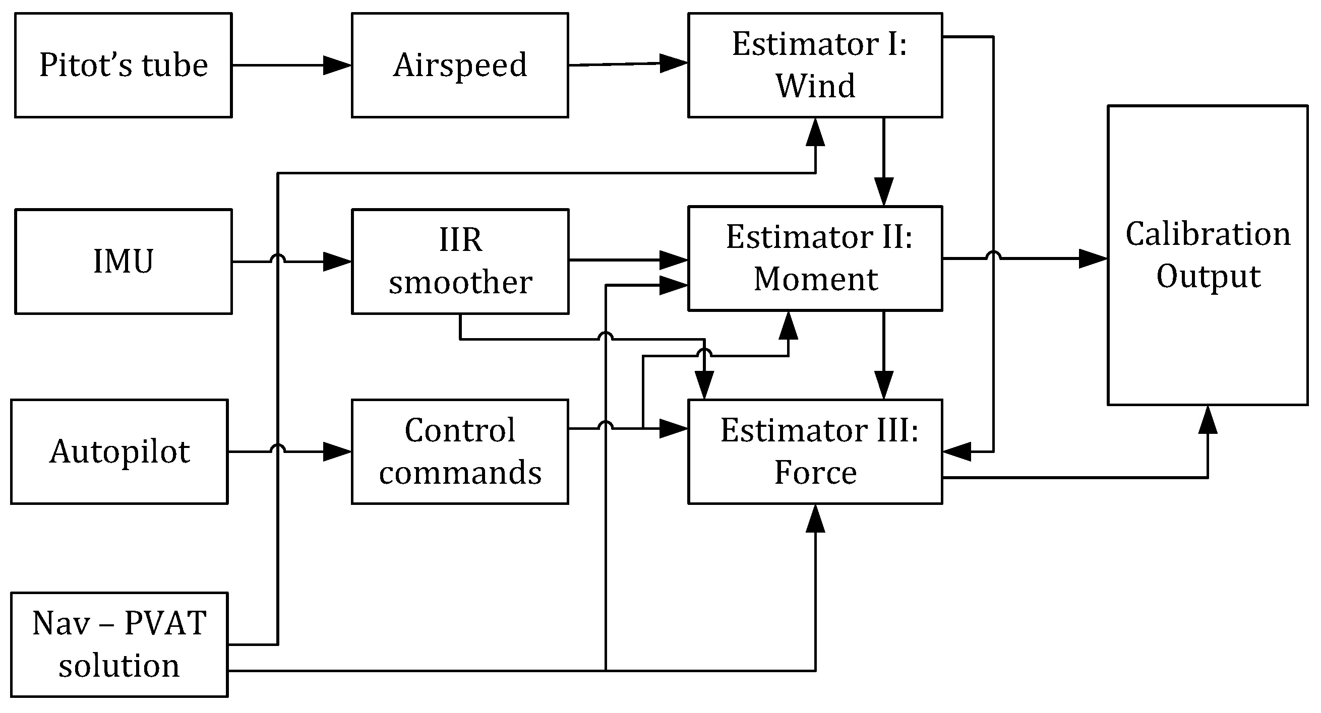
Calibration is carried out using a cascaded architecture comprising three linear estimators, namely, (i) wind, (ii) moments, and (iii) forces, henceforth referred to as WMF. These estimators depend solely on recorded flight data: IMU, GNSS, autopilot control commands (propeller, ailerons, elevator, rudder, and elevons), and pitot measurements. A schematic representation of the calibration procedure is illustrated in Figure 2. We have used the numerical values of aerodynamic model parameters, identified from this approach, to estimate the wind in the application phase.

2.4. Kinematics-Based Wind Estimation

In order to evaluate the correctness of the synthetic wind estimate by a flying fixed-wing drone, we make use of a kinematics-based methodology [3], using GNSS, IMU, and single-hole pitot tube, to obtain another estimate of the wind. The latter is briefly presented in discrete time for the sake of completeness. Let w l R 3 be the wind velocity in the local-level (note that for the kinematic modeling, we represent wind with a separate notation, w l , as compared to x w in the VDM-based system, to avoid confusion) navigation frame denoted as l, and γ R + be the scale factor of the Pitot’s tube. The process model or the state dynamics is described as below:
w k + 1 l γ k + 1 = w k l γ k + w w k w γ k
with { w w k , w γ k } denoting process noise, modeled as Gaussian. That being said, the measurement/observation model is given by the following equation:
z w k = h ( w k l , γ k ) = d T C l k b w k l + p k γ k + ν k ,
where d = 1 0 0 T , p is the airspeed measured by the pitot tube, C l b is the rotation matrix from navigation frame to body frame, z w is drone’s longitudinal velocity, obtained as a result of sensor fusion (INS/GNSS), and ν denotes measurement noise, assumed to be Gaussian. The incorporation of Equations (31) and (32) as the process and observation models of the Kalman filter, respectively, yields the wind velocity in addition to the pitot scale factor.

2.5. Hardware: Conventional Fixed-Wing Drone

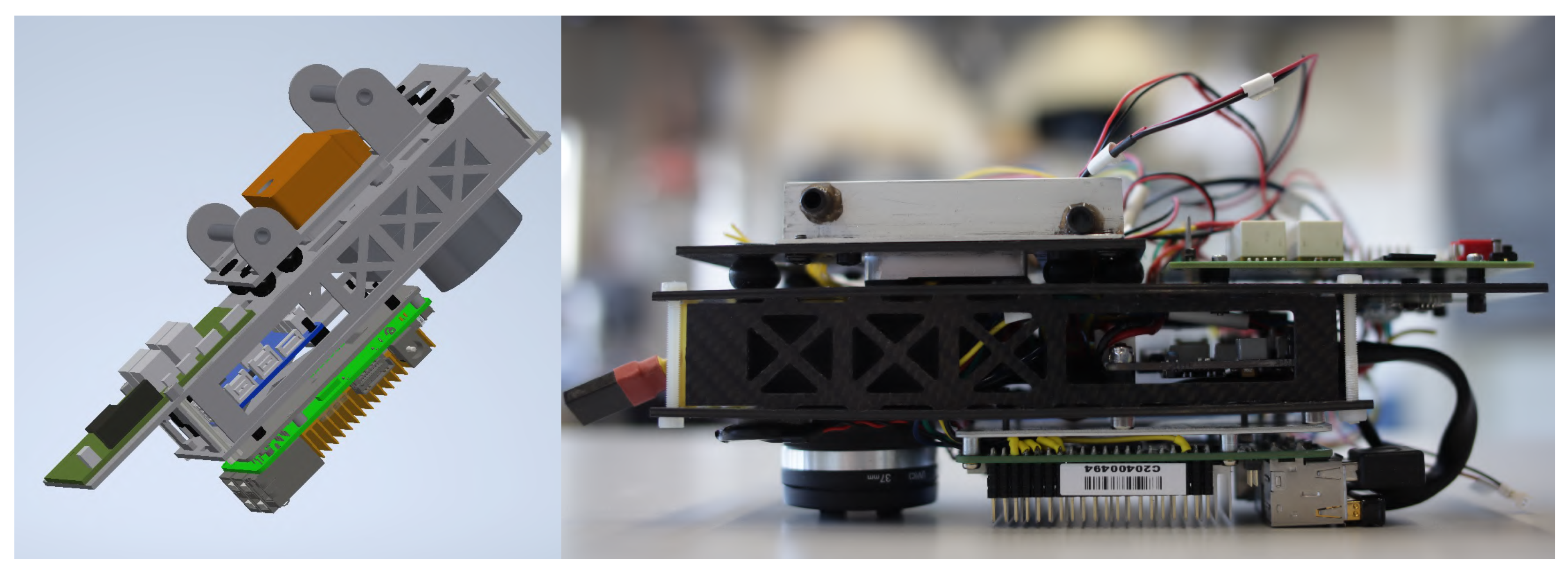
We test the proposed wind-estimation methodology on an in-house-developed conventional aircraft drone—referred to as TP2 henceforth. TP2 has been used in previous research works [4,55,65,69,73] and it accommodates a state-of-the-art payload, open source autopilot, and GNSS receiver. An image of the payload and the drone can be seen in Figure 3 and Figure 4 (top). The payload of the drone consists of several components, including an Inertial Measurement Unit (IMU) called STIM318 (https://www.sensonor.com/products/inertial-measurement-units/stim318/, accessed on 25 October 2024), Sentiboard [74], an onboard computer, and other (unused) components. STIM318 communicates its measurements through one of the serial ports of the Sentiboard [74]. Some of the characteristics of the STIM318 IMU are presented in Table 1. Besides, the Sentiboard, specifically designed for drone applications, is responsible for accurately time-tagging all incoming data with a common GPS reference time. It has a second serial port dedicated to receiving messages from the multi-constellation, multi-frequency TOPCON B125 GNSS receiver, which is equipped with a three-frequency antenna. This receiver allows for the acquisition of both code and phase measurements, essential for post-processing differential position and velocity references. The time reference for the GNSS receiver is provided by a Pulse Per Second (PPS) signal issued at the same frequency as the GNSS messages. The control commands used by the VDM are stored directly in the autopilot system.

2.6. Hardware: Delta-Wing Drone

The delta-wing drone utilized in this analysis is the Concorde S, a custom-built platform, depicted in Figure 4 (bottom). This drone is derived from the commercially available Xeno electric hobby flying wing, which has been modified to support a larger payload bay and an enhanced propulsion system. The Concorde S is equipped with several advanced avionics components. It uses the Pixhawk 4 Holybro as its autopilot, while the Holybro SiK module manages telemetry. Communication is enabled by a Graupner GR-16 2.4 GHz HOTT radio module. For navigation, the system incorporates a JAVAD TR-2S GNSS receiver, which is paired with a TOPGNSS AN-306 antenna. Airspeed is measured using a single-hole Pitot tube from Holybro, and a Beastx Brushless RPM sensor monitors propeller rotation rate. The IMU characteristics of the onboard autopilot are shown in Table 2.

3. Results

Wind velocity is included in the state vector of the VDM-based navigation filter [55], so it can be estimated by the EKF (sensor fusion). That being said, the quality of this estimation depends on the proper initialization of the vehicle’s aerodynamic model parameters. In our approach, we initialize them using the WMF methodology [4,5]. This results in a synthetic estimate of the wind velocity by the VDM-based navigation system without the need for an airspeed sensor. Finally, to evaluate the validity of our approach, we compare the wind velocity estimated by the VDM-based system to that of a conventional kinematic approach, described in Section 2.4. For the kinematics-based method, the measurement noise [see Equation (32)] and process noise for the wind are tuned starting from the values reported in [3]; for the VDM-based system, these values are empirically refined. The numerical value of the process noise for the wind in (i) VDM-based system is tuned to 8.9 × 10 4 m / s 2 / Hz for TP2 and 8.9 × 10 5 m / s 2 / Hz for ConcordeS; conversely, for (ii) the kinematics-based system, this is tuned to 8.3 × 10 3 m / s for both the drones. The measurement noise for Equation (32) is set to 1 m/s (the same as in [3]).
The VDM/kinematics-based wind sensing is tested employing four flights of TP2 and three flights of Concorde S. These flights shall be referred to as STIM6, STIM8, STIM12, and STIM13 for the former drone, whereas for the latter, they will be referred to by TF-1, TF-2, and TF-3. We analyze the data from these flights to compare the estimated wind velocity using the two discussed methodologies.

3.1. Conventional Fixed-Wing Drone

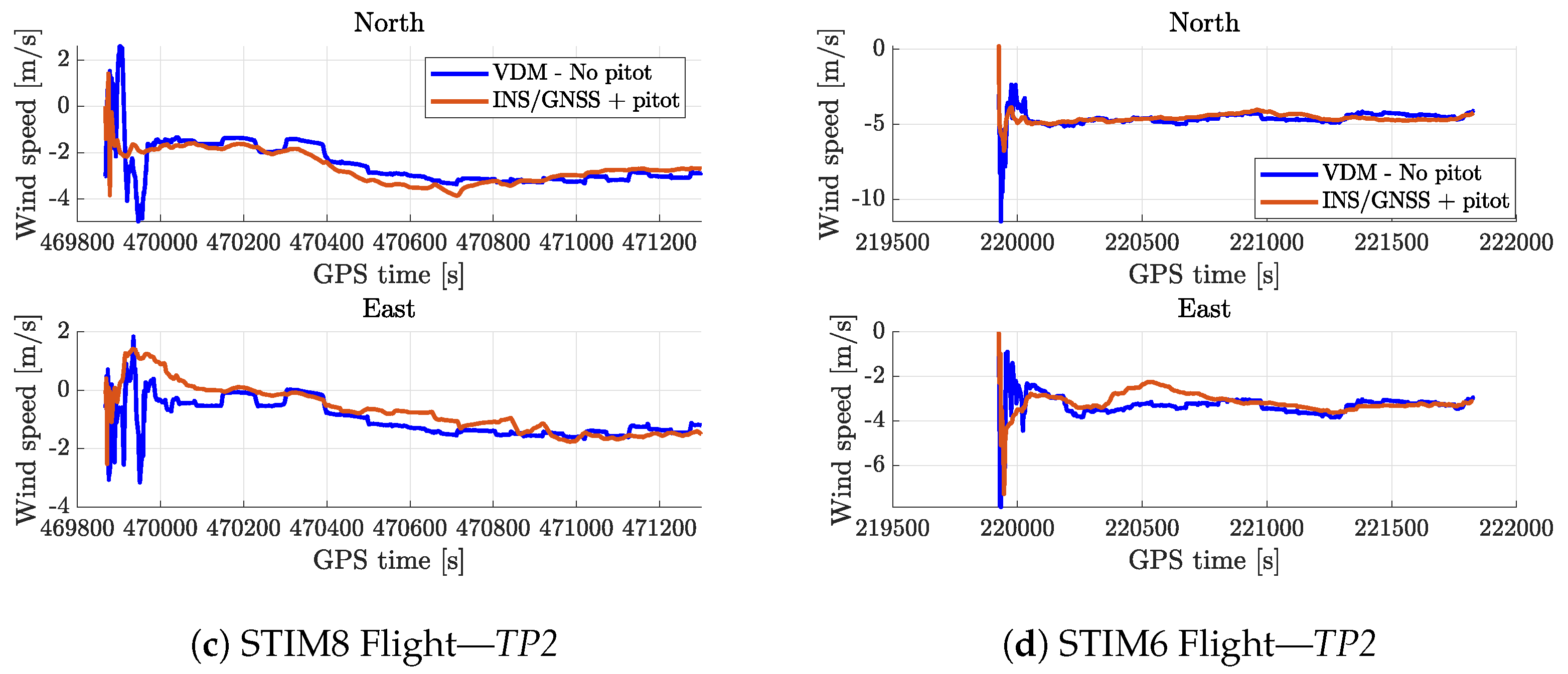
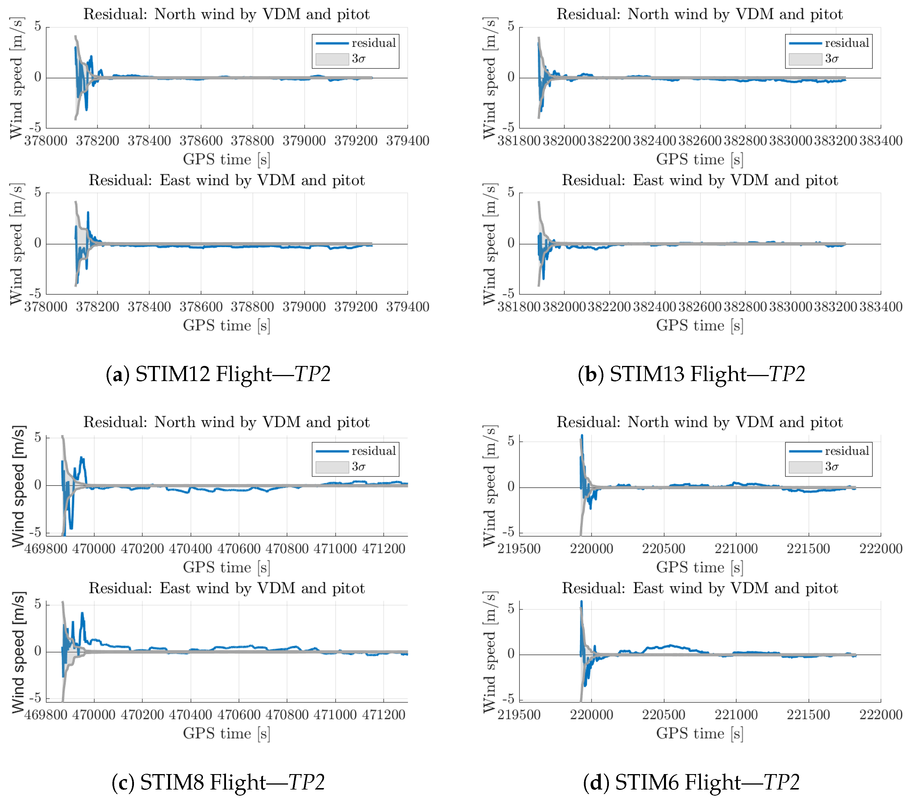
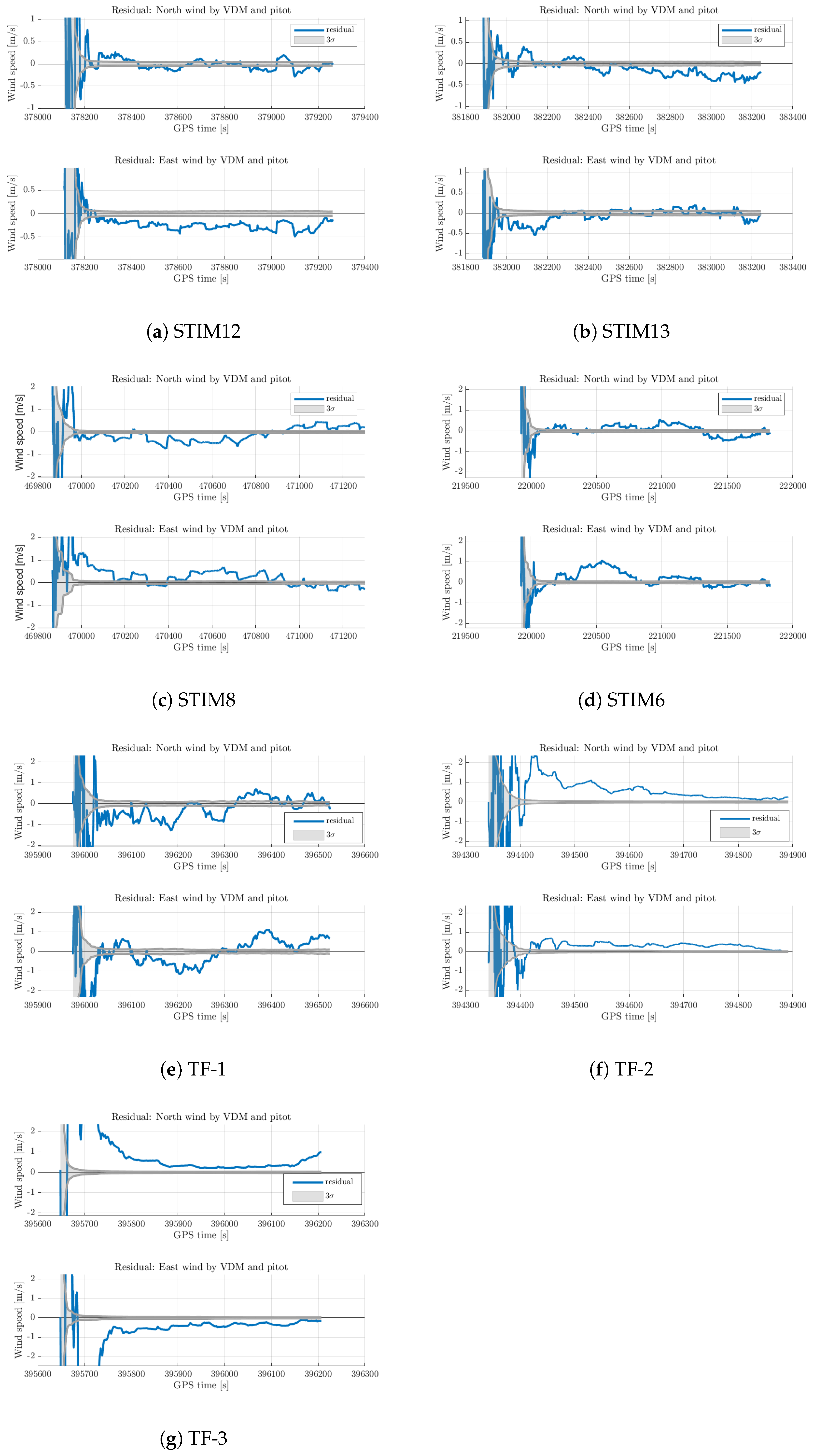
The results of wind estimation for the different flights for TP2 are presented in Figure 5. These results demonstrate that the VDM-based approach can yield a reasonable synthetic wind estimate in comparison to the state-of-the-art kinematics approach relying on a pitot tube (in the absence of an external reference). The difference between the wind estimated by the two methodologies is depicted in Figure 6, along with the predicted standard deviation. The presented results show that the differences generally align with the predicted covariance ( 3 σ ) for the chosen level of driving noise, albeit not perfectly due to unmodeled effects (see Figure 7 for a zoomed version). Similar observations have been reported in [56] (refer to Figure 7 in [56]), where wind residuals tend to converge within the 3 σ bound, but not precisely, as in our results. A summary of the RMSE for the wind estimate is presented later in Table 3 highlighting that on average, the RMSE is 0.4 m/s (a more nuanced discussion on the RMSE calculation is later presented in Section 4). Importantly, it should be emphasized that the magnitude of the wind examined in this study falls within the safe operating range for small and lightweight drones (<10 m/s). Furthermore, the estimated wind magnitude is comparable to to some of the experimental values reported in the previous work by [3] for flights STIM12 and STIM13, whereas the wind velocity is large and more variable in the latter two flights, STIM6 and STIM8. Furthermore, we have tested the need for correct initialization of vehicle aerodynamic model parameters in Appendix A. In sum, the results emphasize the practicality and relevance of the synthetic wind estimation approach without relying on an airspeed sensor and wind tunnel-calibrated model parameters.

3.2. Delta-Wing Drone

We conduct similar tests with the custom-made delta-wing drone, Concorde S, to assess the scalability of the developed framework across different geometries and aerodynamic models. In our previous investigations, we have already proven the scalability of the framework for:
1.
Identification of aerodynamic model parameters (in [4,5]);
2.
Software architecture for real-time navigation (in [69]);
3.
Inclusion of multiple inertial sensors (in [70]).
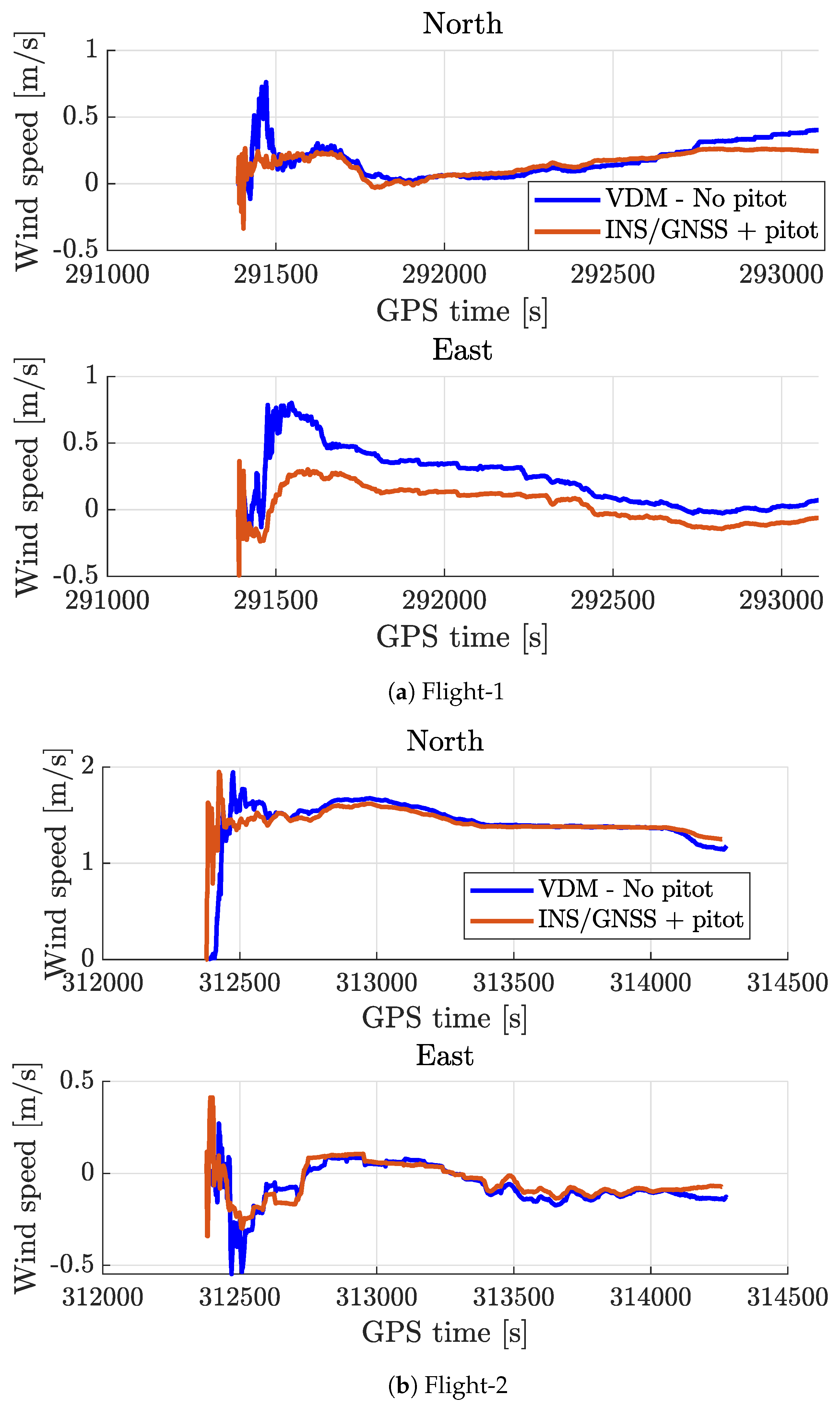
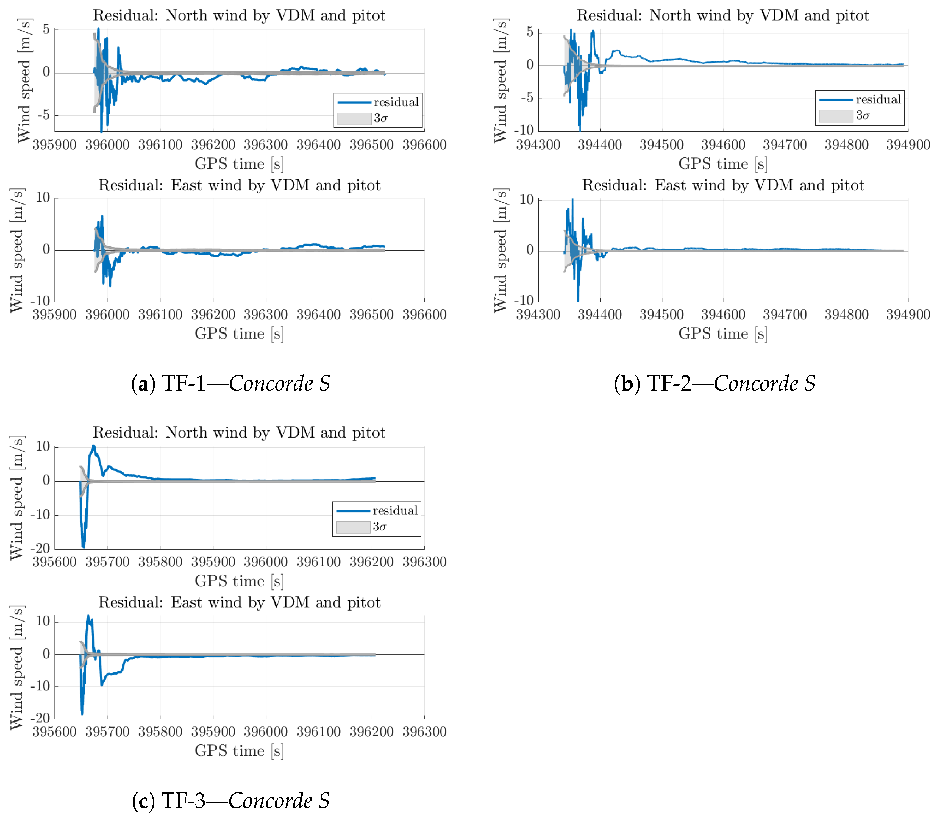
In this contribution, we envisage assessing the scalability of this framework for wind estimation. The wind estimated by the VDM-based and conventional framework is reported in Figure 8, whereas the residuals and 3 σ bounds are portrayed in Figure 9 (see Figure 7 for a zoomed-in version). These results are similar to the ones obtained using the conventional platform and have an average RMSE of 0.74 m/s (see Table 3) for the tested flights. These results altogether show the scalability/modularity of the VDM-EKF framework and the developed WMF methodology to estimate wind without particular hardware at virtually zero cost without relying on airspeed sensors. To further substantiate this point, we report the results for the off-the-shelf delta-wing drone, eBeeX, in Appendix B.

4. Additional Discussion

In this section, we elaborate on certain nuances associated with the proposed methodology and provide references to further reading wherever possible.

4.1. Integrating VDM of Different Drones in the Navigation Filter for Wind Estimation

Without loss of generality, the state dynamics of the navigation filter, applicable to both types of drones (discussed in this work), are modeled using Equations (1)–(7). Although this setup provides a conceptual understanding of the fusion-framework, a step-wise procedure to integrate different aerodynamic models (of possibly different drones) into a VDM-based navigation filter is summarized below.
1.
Aerodynamic models are encapsulated by the terms { f b , M b } in Equations (2) and (4). These models vary depending on the type of the drone. For a conventional fixed-wing drone, the aerodynamic forces and moments are modeled by Equations (8)–(14) and then subsequently integrated into the state-dynamics/observation models (the equations can be found in [55]) via Equations (15) and (16). On the other hand, for a delta-wing drone, the model is governed by Equations (20)–(27) and then integrated into the state dynamics/observations via Equations (15) and (30). Following similar lines, the aerodynamics of a new drone should be modeled so as to obtain a mathematical expression for { f b , M b } . Deducing a new functional model structure is beyond the scope of this paper and more details on this can be found in [68]. It should be noted that we have relied on the models already existing in literature [5,72] for VDM-based wind estimation.
2.
Aerodynamic model parameters, represented as x p , are included in the state vector as described by Equation (7). The dimensionality of x p depends on the structure of the model. For a conventional fixed-wing drone, x p comprises 21 parameters segregated by force and moment identifier as shown in Equations (18) and (19). These are altogether combined in Equation (17). Meanwhile, for a delta-wing drone, 15 parameters constitute x p ; these are segregated by force and moment identifier in Equations (28) and (29) and later combined in Equation (17). For a new drone platform, depending on the nature of its model, the force and moment parameters should be included in the state vector in a way similar to the two drones in our work.
3.
A priori estimates of aerodynamic model parameters are assumed to be known for this work. We rely on [4] for their values for the conventional fixed-wing and [5] for the delta-wing drone. However, for a new drone, methodologies described in [4,5,61] could be used to obtain their a priori values. Note that knowledge of insufficient quality can result in erroneous wind estimates as further highlighted in Appendix A.
4.
Implementation of VDM-based navigation filter is based on [55] and is optimized for numerical stability as discussed in [65]. This step is independent of the choice of the drone and the aerodynamic model.
To execute the above procedure, existence of an aerodynamic model is assumed. We have relied on [72] for the aerodynamic model of a fixed-wing drone, whereas for the delta-wing drone, we have used the model deduced in [5]. It is, therefore, important to first characterize the aerodynamics of a new drone before using it for wind-estimation via the VDM-based navigation system.
In sum, by following the above procedure, a fixed-wing drone could be used to estimate wind velocity without relying on airspeed sensors. As this approach does not use any extra sensors or hardware, it serves as a practical alternative to traditional wind estimation techniques. Having said that, some of the limitations of this approach are later discussed in Section 4.5 for the sake of completeness.

4.2. Benefits of Fixed-Wing Drones

We have used fixed-wing drones, conventional or delta-wing, in this study. Here, we motivate some of the benefits of these platforms to better highlight the relevance of this study. In general, fixed-wing drones offer significant advantages over multi-rotor systems in terms of efficiency and endurance. Unlike multi-rotors that constantly expend energy to maintain lift, fixed-wing drones rely on the aerodynamic lift generated by their wings, allowing them to cover greater distances and remain aloft for longer periods with less power. Besides, delta-wing drones, with their tailless, blended-wing-body design, further increase aerodynamic efficiency by allowing the entire fuselage to contribute to lift. This feature enables them to achieve even longer flight autonomy, which is crucial for extended-duration missions. Their streamlined shape reduces drag, making them ideal for high-speed flights or scenarios where long-term loitering and wide-area coverage are necessary.

4.3. Observability

To assess the observability of a linear time-varying system, the rank of the observability Gramian can be evaluated as discussed in [75]. The system is considered observable if the observability Gramian has a full column rank. On the other hand, for non-linear “control affine” systems [76], the observability is determined by computing the Lie derivatives of the observation (measurement) model to construct a nonlinear observability matrix. If this matrix has full rank, then the system is observable. In non-linear systems with many states, the observability can be empirically evaluated, as described in [55,71]. In this section, we refer to previous works that have contributed to establishing the observability of EKF-based wind estimators.

4.3.1. Observability of GNSS/IMU/Pitot Based Wind Estimators

The utilization of pitot tube, GNSS, and IMU for wind estimation has been widely adopted, but a comprehensive non-linear observability analysis was introduced more recently in [77,78]. In these works, the authors have introduced the concept of conditional observability and presented key findings: firstly, they demonstrated that drone acceleration plays a crucial role in determining heading and IMU biases; secondly, the wind was assumed to be quasi-static, meaning that wind variations are considered to be constant over a small time window. The authors also addressed the maneuver optimization problem and established that certain maneuvers are more important for wind observability than others, utilizing a metric based on the condition number of the observability Gramian. The maneuvers that result in low condition number/high observability include (a) changing the drone’s pitch and heading angle simultaneously; and (b) varying airspeed while changing the orientation of the drone. These contributions have significantly advanced the understanding and analysis of wind observability in the context of the pitot tube, GNSS, and IMU-based estimation methods.

4.3.2. Observability of Synthetic Wind Estimator

In a model-based framework, the wind becomes observable when the drone is undergoing acceleration [56] even when the VDM parameters are constant. However, differentiating between sensor biases and atmospheric disturbances can be challenging [56]. Specifically, inertial sensor biases, including bias instability, can lead to inaccurate wind estimation. As shown in the results for the two drones in Table 3, the RMSE for wind with a lower quality IMU (Concorde S) is worse than that of the higher quality (TP2). Nevertheless, a significant part of IMU biases can be removed before the take off [79].
The wind observability for both kinematics-based and dynamics-based systems relies heavily on regular changes in the drone’s orientation, especially when using a single-hole pitot tube. In this work, the drone’s flight trajectories include two distinct phases: (i) sections with manual piloting or automatic stabilization, where frequent attitude changes occur, and (ii) sections where the drone follows a fully automated “camera-mapping” mission with fewer attitude changes while maintaining optimal airspeed. As a result, the wind observability is limited in the second phase, and for both approaches, when following flight-lines at a constant speed and heading. In such situations, and in the absence of an external reference, the RMSE metric serves more as a comparative agreement between these two methodologies.

4.4. Insights on VDM-Based Navigation Filter: A Focus on Wind-Estimation

Consider a general system, whose state dynamics are modeled as x ˙ = f ( x , u ) , with x being the state and u the known control inputs of a system. Additionally, let z = h ( x , u ) be the measurements from the system. If the system is observable (as briefly discussed in Section 4.3), the state can be estimated via an EKF. In conventional kinematic-based wind sensing, f ( . ) in discrete-time is given by Equation (31) whereas h ( . ) by Equation (32). As the wind, w l , is part of the state [see Equation (31)], it is estimated as a result of the agreement between the longitudinal speed of the drone and airspeed. Likewise, for a VDM-based framework, where f ( . ) is given by Equations (1)–(7) and wind being a part of this system [see Equation (5)], it is estimated as a result of the agreement between IMU measurements and the aerodynamic model. For the sake of completeness, the measurement model of an IMU is presented here:
Z f i m u = C b I f b + Ω ˙ i b b + Ω i b b Ω i b b r b I b + b f + ν f
Z ω i m u = ω i b b + b ω + ν ω
where r b I b , C b I represents the lever arm and boresight between the origin of the body frame and the IMU, { b f , b ω } represent the accelerometer and gyro bias, and { nu f , nu ω } denote the measurement noise.
It is important to note that for wind estimation, using both the kinematics and VDM-based approach, the general observability conditions mentioned in Section 4.3 are fulfilled. Apart from fulfilling these conditions, it is also important to initialize the EKF with reasonably correct values of the aerodynamic model parameters ( x p ) . These parameters are responsible for computing the aerodynamic forces and moments experienced by the drone under different flight conditions. We have utilized data from a reasonably manoeuvered flight, with motions in different directions and changes in attitude, to identify the values of these parameters [4,5]. Although these parameters are also refined with regards to the conflict with IMU measurements, their improper initialization can lead to erroneous wind estimates as highlighted in Appendix A.

4.5. Wind Model

In Ref. [3], the authors assumed that the wind exhibits slow variations over time. In [77,78], a window size equalling three times the sampling period is found to be a necessary condition for the wind to remain constant and thus become observable by model-free estimators. Despite being limited by the rotational motion of the drone, the observable wind variations can be estimated by carefully adjusting the Kalman gain. As suggested in [3], this gain effectively defines a cut-off frequency, allowing wind velocity frequencies below this threshold to be captured while filtering out higher frequencies. Although the authors provide general insights into tuning the Kalman filter, they do not present a systematic methodology. It seems that empirical testing was employed to determine suitable parameter settings—which is precisely what we have also followed for each drone separately. Similar to many other studies utilizing the VDM-EKF framework [4,5,55,58,59,60,61,62,63,64,65,66,67,68,69,70,71,73], the wind model used in [3] followed a random walk process. For the sake of completeness, we would like to mention that the wind was modeled as a first-order Gauss Markov process in [77,78,80]. In our work, given the close association with previous research on the VDM-EKF framework, we also employ the same stochastic model, namely, a random walk. The magnitude of the white noise in the random walk process plays a critical role in wind estimation and we have also relied on empirical testing to set its value. If the process noise is set to be low then the estimation of wind by the two approaches matches very well. However, once set too low, the predicted uncertainty becomes unrealistically optimistic and the system does not adapt well to wind variations. From a practical point of view, this does not seem very plausible, and hence, the process noise is tuned to achieve more realistic covariance values. In this sense, having an accurate local reference could significantly improve the tuning of the respective filter parameters.

4.6. Limitations

While the VDM-based navigation system has shown promising results in terms of wind estimation, the approach comes with a few assumptions that could limit its use in certain situations. Firstly, it is assumed that the aerodynamics of the drones can be represented using low-fidelity models. Secondly, the aerodynamic models are assumed to be linear with respect to model parameters ( C ); this is a necessary condition to identify their a priori values from recorded flight data (no wind-tunnel experimentation). Thirdly, the identification procedure relies on measurements from lightweight sensors, such as pitot tubes/pressure sensors and IMUs; this introduces inherent errors that can impact estimation accuracy. That being said, the VDM-EKF framework does the job of refining these coarse estimates during flight [65]. Finally, tuning the wind process noise is a slightly tedious process, especially in the absence of an external wind reference of sufficient quality.

5. Conclusions

The results presented in this study have altogether shown that wind velocity can be synthetically estimated without using an airspeed sensor on small-fixed-wing drones. Where most of the existing works have relied on such sensors or wind-tunnel-calibrated aerodynamics, our approach relies on neither of the above, thus standing out as a novel contribution to the state of the art. We have also proven the generalization of our methodology by demonstrating its effectiveness on drones with different geometry, aerodynamic models, control surfaces, and quality of inertial sensors. The versatility of our approach has been found to come from the characterization of the underlying aerodynamics of individual drones in terms of functional models of forces and moments that are linear with respect to model parameters. In sum, our methodology entails identifying these parameters a priori from recorded flight data, after which they are plugged into a VDM-based navigation filter, where they are fused with GNSS and IMU data to yield a wind-velocity estimate without relying on an airspeed sensor. As our methodology does not utilize any additional hardware or external calibration equipment, it serves as an alternative to conventional approaches, or simply a redundant analytical wind sensor, at virtually no extra cost. In conclusion, our method can either serve as a backup wind sensor during potential sensor failure or perhaps be used as a standalone solution in environments where the existing pressure probes are susceptible to blockages or there are space and power constraints on the side of the drone itself.

Author Contributions

Conceptualization, A.S., G.F.L., P.L., and J.S.; methodology, A.S., G.F.L., P.L., and J.S.; software, G.F.L., A.S., and P.L.; validation, A.S., G.F.L., P.L., and J.S.; formal analysis, A.S.; investigation, A.S., P.L., and G.F.L.; resources, J.S.; writing—original draft preparation, A.S.; writing—review and editing, J.S., A.S., G.F.L., and P.L.; visualization, A.S., P.L., and G.F.L.; supervision, J.S.; project administration, J.S.; funding acquisition, J.S. All authors have read and agreed to the published version of the manuscript.

Funding

This project has received funding from the European Union’s Horizon 2020 research and innovation program under the Marie Skłodowska-Curie grant agreement No. 754354. Additionally, this work has been supported by Swiss DDPS (armasuisse) under contract ARF00-009.

Institutional Review Board Statement

Not applicable.

Informed Consent Statement

Not applicable.

Data Availability Statement

The data presented in this study are available on request from the corresponding author. The data are not publicly available due to research contractual restrictions.

Acknowledgments

We would like to thank Mohammad Abedini and Kenneth Joseph Paul, colleagues from the Geodetic Engineering Laboratory, EPFL for their contribution to hardware development.

Conflicts of Interest

The authors declare no conflicts of interest.

Abbreviations

The following abbreviations are used in this manuscript:
VDMVehicle Dynamic Model
GNSSGlobal Navigation Satellite System
IMUInertial Measurement Unit
ADSAir Data System
AHRSAttitude and Heading Reference System
SWAPSize, Weight and Power
LOSLine of Sight
BVLOSBeyond Visual Line of Sight
EKFExtended Kalman Filter
INSInertial Navigation System
FADSFlush Air Data System
AOAAngle of attack
SSASideslip angle
RLSRecursive Least Squares
ECEFEarth-Centered Earth Fixed
NEDNorth, East Down
WMFWind, Moment Force
CADComputer-Aided Design
PPSPulse Per Second
RPMRotation Per Minute
RMSERoot Mean Square Error
GPSGlobal Positioning System

Appendix A. Adversarial Testing

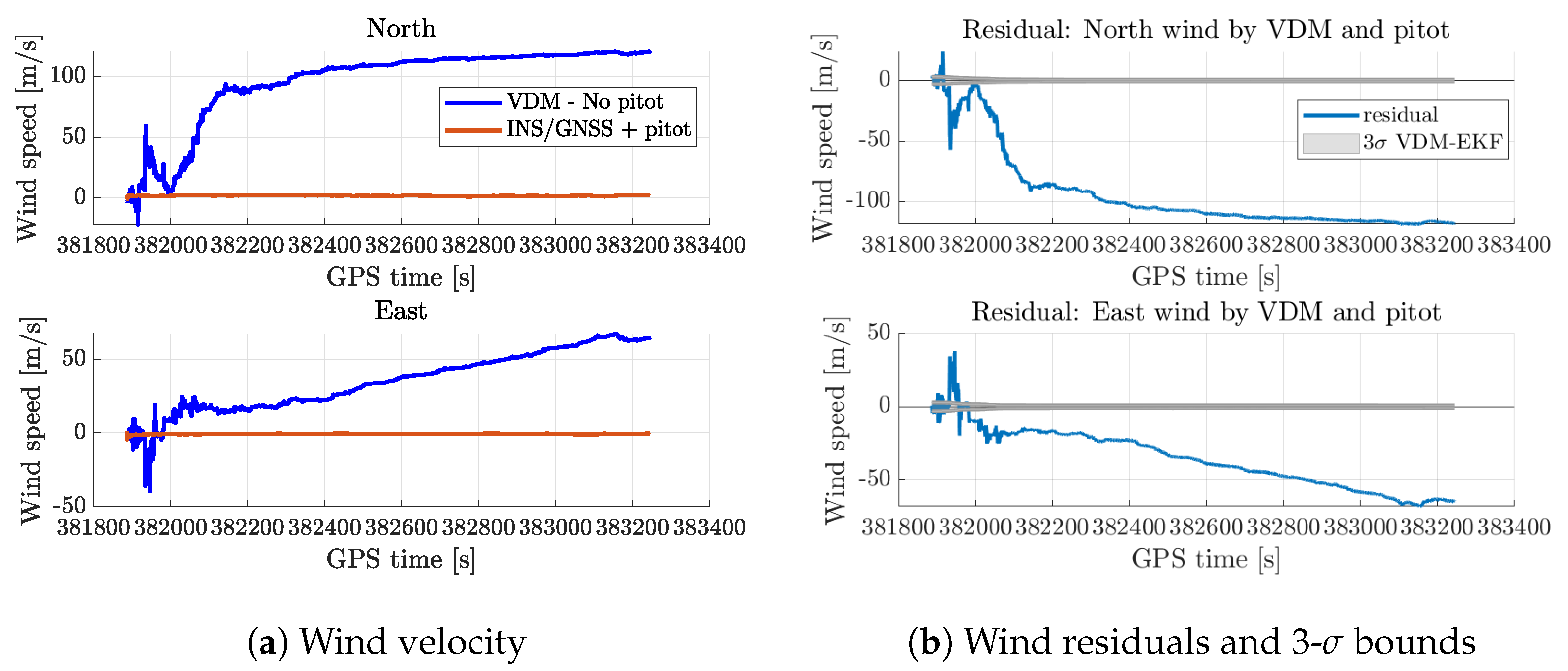
To underscore the significance of aerodynamic identification for wind estimation, we intentionally initialize the VDM-EKF framework for the STIM13 flight with incorrect aerodynamic model parameters. Various initialization attempts were made by randomly assigning values to these parameters, drawn from both Gaussian and uniform distributions. However, all of these initialization attempts resulted in numerical instability as discussed previously in [4]. Nonetheless, when all the parameters were initialized with a very small value, specifically 10 5 in our case, the estimated wind exhibited significant errors. This is evident in Figure A1a,b. Therefore, it becomes evident that reasonable prior knowledge of these parameters is crucial for wind estimation.
Figure A1. Wind estimated using incorrect VDM parameters for TP2—STIM13.
Atmosphere 15 01339 g0a1

Appendix B. eBeeX Wind Estimation

To further test the proposed synthetic wind estimation approach, we have used another delta-wing drone, eBeex, shown in Figure A2, whose VDM is presented in [4,62]. Although the sub-optimality of the aerodynamic model is discussed in [4,5,66], the results for wind estimation are still promising, as presented in Figure A3.
Figure A2. eBeeX drone.
Atmosphere 15 01339 g0a2
Figure A3. Wind estimated by eBeex.
Atmosphere 15 01339 g0a3

References

  1. O’Shea, O.R.; Hamann, M.; Smith, W.; Taylor, H. Predictable pollution: An assessment of weather balloons and associated impacts on the marine environment—An example for the Great Barrier Reef, Australia. Mar. Pollut. Bull. 2014, 79, 61–68. [Google Scholar] [CrossRef]
  2. Meier, K.; Hann, R.; Skaloud, J.; Garreau, A. Wind Estimation with Multirotor UAVs. Atmosphere 2022, 13, 551. [Google Scholar] [CrossRef]
  3. Johansen, T.A.; Cristofaro, A.; Sørensen, K.; Hansen, J.M.; Fossen, T.I. On estimation of wind velocity, angle-of-attack and sideslip angle of small UAVs using standard sensors. In Proceedings of the 2015 International Conference on Unmanned Aircraft Systems (ICUAS), Denver, CO, USA, 9–12 June 2015; pp. 510–519. [Google Scholar] [CrossRef]
  4. Sharma, A.; Laupré, G.F.; Skaloud, J. Identifying Aerodynamics of Small Fixed-Wing Drones Using Inertial Measurements for Model-Based Navigation. NAVIGATION J. Inst. Navig. 2023, 70, navi.611. [Google Scholar] [CrossRef]
  5. Longobardi, P.; Sharma, A.; Skaloud, J. Identifying Aerodynamics of Delta-Wing Drones for Model-Based Navigation: A Comparative Study. IEEE Access 2024, 12, 91649–91663. [Google Scholar] [CrossRef]
  6. Borup, K.T.; Fossen, T.I.; Johansen, T.A. A nonlinear model-based wind velocity observer for unmanned aerial vehicles. IFAC-PapersOnLine 2016, 49, 276–283. [Google Scholar] [CrossRef]
  7. Wenz, A.; Johansen, T.A. Estimation of wind velocities and aerodynamic coefficients for UAVs using standard autopilot sensors and a moving horizon estimator. In Proceedings of the 2017 International Conference on Unmanned Aircraft Systems (ICUAS), Miami, FL, USA, 13–16 June 2017; pp. 1267–1276. [Google Scholar] [CrossRef]
  8. Wenz, A.; Johansen, T.A. Real-Time Moving Horizon Estimation of Air Data Parameters and Wind Velocities for fixed-wing UAVs. In Proceedings of the 2020 International Conference on Unmanned Aircraft Systems (ICUAS), Athens, Greece, 1–4 September 2020; pp. 998–1006. [Google Scholar] [CrossRef]
  9. Wenz, A.; Johansen, T.A. Moving horizon estimation of air data parameters for UAVs. IEEE Trans. Aerosp. Electron. Syst. 2019, 56, 2101–2121. [Google Scholar] [CrossRef]
  10. Flight Safety Foundation. 2022. Available online: http://aviation-safety.net/database (accessed on 14 July 2022).
  11. 14 AC Part 135 Air Carrier and Operator Certification. 2022. Available online: https://www.faa.gov/licenses_certificates/airline_certification/135_certification (accessed on 14 July 2022).
  12. Kurtz, J.; Wittig, S.; O’Byrne, S. Applicability of a counterpropagating laser airspeed sensor to aircraft flight regimes. J. Aircr. 2016, 53, 439–450. [Google Scholar] [CrossRef]
  13. Wheeler, T.J.; Seiler, P.; Packard, A.K.; Balas, G.J. Performance analysis of fault detection systems based on analytically redundant linear time-invariant dynamics. In Proceedings of the 2011 American Control Conference, San Francisco, CA, USA, 29 June–1 July 2011; pp. 214–219. [Google Scholar] [CrossRef]
  14. Zeis, J., Jr.; Lambert, H.; Calcio, R.; Gleason, D. Angle of attack estimation using an inertial reference platform. In Proceedings of the 15th Atmospheric Flight Mechanics Conference, Minneapolis, MN, USA, 15–17 August 1988. [Google Scholar] [CrossRef]
  15. Myschik, S.; Holzapfel, F.; Sachs, G. Low-cost sensor based integrated airdata and navigation system for general aviation aircraft. In Proceedings of the AIAA Guidance, Navigation and Control Conference and Exhibit, Honolulu, HI, USA, 18–21 August 2008; p. 7423. [Google Scholar] [CrossRef]
  16. Murch, A. A flight control system architecture for the NASA AirSTAR flight test infrastructure. In Proceedings of the AIAA Guidance, Navigation and Control Conference and Exhibit, Honolulu, HI, USA, 18–21 August 2008; p. 6990. [Google Scholar] [CrossRef]
  17. Colgren, R. The Feasibility of using an INS for control system feedbacks. In Proceedings of the AIAA and SAE, 1998 World Aviation Conference, Anaheim, CA, USA, 28–30 September 1998; p. 5517. [Google Scholar] [CrossRef]
  18. Colgren, R.; Frye, M.; Olson, W. A proposed system architecture for estimation of angle-of-attack and sideslip angle. In Proceedings of the Guidance, Navigation, and Control Conference and Exhibit, Portland, OR, USA, 9–11 August 1999; p. 4078. [Google Scholar] [CrossRef]
  19. Colgren, R.; Martin, K. Flight Test validation of sideslip estimation using inertial accelerations. In Proceedings of the AIAA Guidance, Navigation, and Control Conference and Exhibit, Dever, CO, USA, 14–17 August 2000; p. 4448. [Google Scholar] [CrossRef]
  20. Colgren, R.D. Method and System for Estimation and Correction of Angle-of-Attack and Sideslip Angle from Acceleration Measurements. US Patent 6,273,370, 14 August 2001. [Google Scholar]
  21. Wise, K.A. Computational Air Data System for Angle-of-Attack and Angle-of-Sideslip. US Patent 6,928,341, 9 August 2005. [Google Scholar]
  22. Wise, K. Flight testing of the X-45A J-UCAS computational alpha-beta system. In Proceedings of the AIAA Guidance, Navigation, and Control Conference and Exhibit, Keystone, CO, USA, 21–24 August 2006. [Google Scholar] [CrossRef]
  23. Giebel, G.; Schmidt Paulsen, U.; Bange, J.; la Cour-Harbo, A.; Reuder, J.; Mayer, S.; van der Kroonenberg, A.; Mølgaard, J. Autonomous Aerial Sensors for Wind Power Meteorology—A Pre-Project; Danmarks Tekniske Universitet: Copenhagen, Denmark, 2012. [Google Scholar]
  24. Emeis, S.; Schafer, K.; Munkel, C. Surface-based remote sensing of the mixing-layer height-a review. Meteorol. Z. 2008, 17, 621–630. [Google Scholar] [CrossRef]
  25. Lenschow, D. The Measurement of Air Velocity and Temperature Using the NCAR Buffalo Aircraft Measuring System; National Center for Atmospheric Research Boulder: Boulder, CO, USA, 1972. [Google Scholar]
  26. Cho, J.Y.; Newell, R.E.; Anderson, B.E.; Barrick, J.D.; Thornhill, K.L. Characterizations of tropospheric turbulence and stability layers from aircraft observations. J. Geophys. Res. Atmos. 2003, 108. [Google Scholar] [CrossRef]
  27. Aberson, S.D.; Franklin, J.L. Impact on hurricane track and intensity forecasts of GPS dropwindsonde observations from the first-season flights of the NOAA Gulfstream-IV jet aircraft. Bull. Am. Meteorol. Soc. 1999, 80, 421–428. [Google Scholar] [CrossRef]
  28. Elston, J.; Argrow, B.; Stachura, M.; Weibel, D.; Lawrence, D.; Pope, D. Overview of small fixed-wing unmanned aircraft for meteorological sampling. J. Atmos. Ocean. Technol. 2015, 32, 97–115. [Google Scholar] [CrossRef]
  29. Spiess, T.; Bange, J.; Buschmann, M.; Vorsmann, P. First application of the meteorological Mini-UAV’M2AV’. Meteorol. Z. 2007, 16, 159–170. [Google Scholar] [CrossRef]
  30. Mansour, M.; Kocer, G.; Lenherr, C.; Chokani, N.; Abhari, R.S. Seven-sensor fast-response probe for full-scale wind turbine flowfield measurements. J. Eng. Gas Turbines Power 2011, 133, 081601. [Google Scholar] [CrossRef]
  31. Reineman, B.D.; Lenain, L.; Statom, N.M.; Melville, W.K. Development and testing of instrumentation for UAV-based flux measurements within terrestrial and marine atmospheric boundary layers. J. Atmos. Ocean. Technol. 2013, 30, 1295–1319. [Google Scholar] [CrossRef]
  32. Van den Kroonenberg, A.; Martin, T.; Buschmann, M.; Bange, J.; Vörsmann, P. Measuring the wind vector using the autonomous mini aerial vehicle M 2 AV. J. Atmos. Ocean. Technol. 2008, 25, 1969–1982. [Google Scholar] [CrossRef]
  33. Wildmann, N.; Ravi, S.; Bange, J. Towards higher accuracy and better frequency response with standard multi-hole probes in turbulence measurement with remotely piloted aircraft (RPA). Atmos. Meas. Tech. 2014, 7, 1027–1041. [Google Scholar] [CrossRef]
  34. Kocer, G.; Mansour, M.; Chokani, N.; Abhari, R.S.; Müller, M. Full-scale wind turbine near-wake measurements using an instrumented uninhabited aerial vehicle. J. Sol. Energy Eng. 2011, 133, 041011. [Google Scholar] [CrossRef]
  35. Reuder, J.; Jonassen, M.O. First results of turbulence measurements in a wind park with the Small Unmanned Meteorological Observer SUMO. Energy Procedia 2012, 24, 176–185. [Google Scholar] [CrossRef]
  36. Wildmann, N.; Hofsäß, M.; Weimer, F.; Joos, A.; Bange, J. MASC—A small Remotely Piloted Aircraft (RPA) for wind energy research. Adv. Sci. Res. 2014, 11, 55–61. [Google Scholar] [CrossRef]
  37. Dias, N.; Gonçalves, J.; Freire, L.; Hasegawa, T.; Malheiros, A. Obtaining potential virtual temperature profiles, entrainment fluxes, and spectra from mini unmanned aerial vehicle data. Bound.-Layer Meteorol. 2012, 145, 93–111. [Google Scholar] [CrossRef]
  38. Crowe, W.; Davis, K.; la Cour-Harbo, A.; Vihma, T.; Lesenkov, S.; Eppi, R.; Weatherhead, E.; Liu, P.; Raustein, M.; Abrahamsson, M.; et al. Enabling Science Use of Unmanned Aircraft Systems for Arctic Environmental Monitoring; Arctic Monitoring and Asessment Programme (AMAP): Oslo, Norway, 2012. [Google Scholar]
  39. Houston, A.L.; Argrow, B.; Elston, J.; Lahowetz, J.; Frew, E.W.; Kennedy, P.C. The collaborative Colorado–Nebraska unmanned aircraft system experiment. Bull. Am. Meteorol. Soc. 2012, 93, 39–54. [Google Scholar] [CrossRef]
  40. Balsley, B.B.; Lawrence, D.A.; Woodman, R.F.; Fritts, D.C. Fine-scale characteristics of temperature, wind, and turbulence in the lower atmosphere (0–1,300 m) over the south Peruvian coast. Bound.-Layer Meteorol. 2013, 147, 165–178. [Google Scholar] [CrossRef]
  41. Quindlen, J.; Langelaan, J. Flush air data sensing for soaring-capable UAVs. In Proceedings of the 51st AIAA Aerospace Sciences Meeting Including the New Horizons Forum and Aerospace Exposition, Grapevine, TX, USA, 7–10 January 2013. [Google Scholar] [CrossRef]
  42. Samy, I.; Postlethwaite, I.; Gu, D.W.; Green, J. Neural-network-based flush air data sensing system demonstrated on a mini air vehicle. J. Aircr. 2010, 47, 18–31. [Google Scholar] [CrossRef]
  43. Whitmore, S.; Cobleigh, B.; Haering, E., Jr. Design and calibration of the X-33 flush airdata sensing (FADS) system. In Proceedings of the 36th AIAA Aerospace Sciences Meeting and Exhibit, Reno, NV, USA, 12–15 January 1998; p. 201. [Google Scholar] [CrossRef]
  44. Pruett, C.D.; Wolf, H.; Heck, M.L.; Siemers, P.M., III. Innovative air data system for the space shuttle orbiter. J. Spacecr. Rocket. 1983, 20, 61–69. [Google Scholar] [CrossRef]
  45. Shen, H.; Xu, Y.; Remeikas, C. Pitch control of a micro air vehicle with micropressure sensors. J. Aircr. 2013, 50, 239–248. [Google Scholar] [CrossRef]
  46. Shyy, W.; Bernal, L.; Yeo, D.; Atkins, E. Aerodynamic sensing for a fixed wing uas operating at high angles of attack. In Proceedings of the AIAA Atmospheric Flight Mechanics Conference, Minneapolis, MN, USA, 13–16 August 2012. [Google Scholar] [CrossRef]
  47. Marino, M.; Ravi, S.; Watkins, S. Optimum location of pressure measurments around a wing as a dynamic control input in smooth and turbulent conditions. In Proceedings of the 28th International Congress of the Aeronautical Sciences; ICAS: Bonn, Germany, 2012; Volume 2, pp. 955–962. [Google Scholar]
  48. Mohamed, A.; Watkins, S.; Fisher, A.; Marino, M.; Massey, K.; Clothier, R. Bioinspired wing-surface pressure sensing for attitude control of micro air vehicles. J. Aircr. 2015, 52, 827–838. [Google Scholar] [CrossRef]
  49. Laurence, R.J., III; Argrow, B.M.; Frew, E.W. Wind tunnel results for a distributed flush airdata system. J. Atmos. Ocean. Technol. 2017, 34, 1519–1528. [Google Scholar] [CrossRef]
  50. Thompson, K.; Xu, Y.; Dickinson, B.T. Aerodynamic moment model calibration from distributed pressure arrays. J. Aircr. 2017, 54, 716–723. [Google Scholar] [CrossRef]
  51. Fei, H.; Zhu, R.; Zhou, Z.; Wang, J. Aircraft flight parameter detection based on a neural network using multiple hot-film flow speed sensors. Smart Mater. Struct. 2007, 16, 1239. [Google Scholar] [CrossRef]
  52. Que, R.; Zhu, R. Aircraft aerodynamic parameter detection using micro hot-film flow sensor array and BP neural network identification. Sensors 2012, 12, 10920–10929. [Google Scholar] [CrossRef]
  53. Keshavan, J.; Humbert, J.S. MAV stability augmentation using weighted outputs from distributed hair sensor arrays. In Proceedings of the 2010 American Control Conference, Baltimore, MD, USA, 30 June–2 July 2010; pp. 4445–4450. [Google Scholar] [CrossRef]
  54. Lee, L.; Dickinson, B.; Baur, J.; Reich, G. Embedded Sensors for Autonomous Air Systems, LRIR 09rw10cor. 2012. Available online: https://api.semanticscholar.org/CorpusID:136535505 (accessed on 25 October 2024).
  55. Khaghani, M.; Skaloud, J. Assessment of VDM-based autonomous navigation of a UAV under operational conditions. Robot. Auton. Syst. 2018, 106, 152–164. [Google Scholar] [CrossRef]
  56. Lie, F.A.P.; Gebre-Egziabher, D. Synthetic air data system. J. Aircr. 2013, 50, 1234–1249. [Google Scholar] [CrossRef]
  57. Owens, B.; Cox, D.; Morelli, E. Development of a low-cost sub-scale aircraft for flight research: The FASER project. In Proceedings of the 25th AIAA Aerodynamic Measurement Technology and Ground Testing Conference, San Francisco, CA, USA, 5–8 June 2006. [Google Scholar] [CrossRef]
  58. Mwenegoha, H.A.; Moore, T.; Pinchin, J.; Jabbal, M. Error characteristics of a model-based integration approach for fixed-wing unmanned aerial vehicles. J. Navig. 2021, 74, 1353–1366. [Google Scholar] [CrossRef]
  59. Mwenegoha, H.A.; Moore, T.; Pinchin, J.; Jabbal, M. Enhanced fixed wing UAV navigation in extended GNSS outages using a vehicle dynamics model and raw GNSS observables. In Proceedings of the 32nd International Technical Meeting of the Satellite Division of The Institute of Navigation (ION GNSS+ 2019), Miami, FL, USA, 16–20 September 2019; pp. 2552–2565. [Google Scholar] [CrossRef]
  60. Mwenegoha, H.A.; Moore, T.; Pinchin, J.; Jabbal, M. Model-based autonomous navigation with moment of inertia estimation for unmanned aerial vehicles. Sensors 2019, 19, 2467. [Google Scholar] [CrossRef]
  61. Mwenegoha, H.A.; Moore, T.; Pinchin, J.; Jabbal, M. A model-based tightly coupled architecture for low-cost unmanned aerial vehicles for real-time applications. IEEE Access 2020. [Google Scholar] [CrossRef]
  62. Laupré, G.; Longobardi, P.; Skaloud, J.; Charlaix, J.C. Model Based Navigation of Delta-Wing UAV-In-Flight Calibration and Autonomous Performance. Eur. J. Navig. 2021, 21, 22–30. [Google Scholar]
  63. Laupré, G.; Skaloud, J. On the self-calibration of aerodynamic coefficients in vehicle dynamic model-based navigation. Drones 2020, 4, 32. [Google Scholar] [CrossRef]
  64. Laupré, G.; Khaghani, M.; Skaloud, J. Sensitivity to time delays in VDM-based navigation. Drones 2019, 3, 11. [Google Scholar] [CrossRef]
  65. Laupré, G.; Pirlet, L.; Skaloud, J. Reliable strategies for implementing model-based navigation on fixed-wing drones. J. Navig. 2023, 76, 413–431. [Google Scholar] [CrossRef]
  66. Longobardi, P.; Skaloud, J. On the scalability of experimentally determined aerodynamic model for model-based navigation on a delta-wing UAV. In Proceedings of the 2023 IEEE 10th International Workshop on Metrology for AeroSpace (MetroAeroSpace), Milan, Italy, 19–21 June 2023; pp. 19–24. [Google Scholar] [CrossRef]
  67. Longobardi, P.; Bonneau, G.; Skaloud, J. Wind Tunnel Characterization of a Delta-Wing UAV for—Model-Based Navigation. In Proceedings of the 2023 Aerospace Europe Conference 10th EUCASS and 9th CEAS Conference, CEAS, Lausanne, Switzerland, 9–13 July 2023. [Google Scholar] [CrossRef]
  68. Longobardi, P.; Skaloud, J. Aerodynamic Modeling of a Delta-Wing UAV for ModelBased Navigation. CEAS Aeronaut. J. 2024, 15, 283–301. [Google Scholar] [CrossRef]
  69. Laupré, G.F.; Sharma, A.; Skaloud, J. VDMNav: Software Architecture for Aerodynamically Constrained Navigation on Small Fixed-Wing Drones. IEEE Robot. Autom. Lett. 2024, 9, 2869–2876. [Google Scholar] [CrossRef]
  70. Sharma, A.; Gilgien, S.; Skaloud, J. Model-Based Fusion of GNSS and Multiple-IMUs. In Proceedings of the 2024 11th International Workshop on Metrology for AeroSpace (MetroAeroSpace), Lublin, Poland, 3–5 June 2024; pp. 266–271. [Google Scholar] [CrossRef]
  71. Khaghani, M.; Skaloud, J. Autonomous Vehicle Dynamic Model-Based Navigation for Small UAVs. NAVIGATION J. Inst. Navig. 2016, 63, 345–358. [Google Scholar] [CrossRef]
  72. Ducard, G.J. Nonlinear Aircraft Model; Chapter Fault-tolerant Flight Control and Guidance Systems: Practical Methods for Small Unmanned Aerial Vehicles; Springer: London, UK, 2009; pp. 27–41. [Google Scholar] [CrossRef]
  73. Laupré, G.; Skaloud, J. Calibration of Fixed-Wing UAV Aerodynamic Coefficients with Photogrammetry for VDM-based Navigation. In Proceedings of the 2021 International Technical Meeting of The Institute of Navigation, Online, 25–28 January 2021; pp. 775–786. [Google Scholar] [CrossRef]
  74. Albrektsen, S.M.; Johansen, T.A. User-configurable timing and navigation for UAVs. Sensors 2018, 18, 2468. [Google Scholar] [CrossRef]
  75. Anderson, B.D.; Moore, J.B. Optimal Filtering; Dover Publications, Inc.: New York, NY, USA, 2005. [Google Scholar]
  76. Sastry, S. Nonlinear Systems Analysis, Stability, and Control; Springer: New York, NY, USA, 1999. [Google Scholar]
  77. Sun, K.; Regan, C.D.; Egziabher, D.G. GNSS/INS based estimation of air data and wind vector using flight maneuvers. In Proceedings of the 2018 IEEE/ION Position, Location and Navigation Symposium (PLANS), Monterey, CA, USA, 23–26 April 2018; pp. 838–849. [Google Scholar] [CrossRef]
  78. Sun, K.; Regan, C.D.; Gebre-Egziabher, D. Observability and performance analysis of a model-free synthetic air data estimator. J. Aircr. 2019, 56, 1471–1486. [Google Scholar] [CrossRef]
  79. Burkhard, J.; Sharma, A.; Skaloud, J. Linear Estimation of Deterministic Accelerometer Errors. NAVIGATION J. Inst. Navig. 2024, 71, navi.656. [Google Scholar] [CrossRef]
  80. Paul, K.J.; Cucci, D.A.; Skaloud, J. Model-based constraints for trajectory determination of quad-copters: Design, calibration & merits for direct orientation. ISPRS Open J. Photogramm. Remote Sens. 2023, 7, 100030. [Google Scholar] [CrossRef]
Figure 1. VDM-based navigation system. Image courtesy: Ref. [71].
Atmosphere 15 01339 g001
Figure 2. Aerodynamic calibration procedure. Image courtesy: Ref. [4].
Atmosphere 15 01339 g002
Figure 3. TP2 payload: (left) CAD model; (right) practical realization.
Atmosphere 15 01339 g003
Figure 4. Drones: (top) TP2; (bottom) Concorde S.
Atmosphere 15 01339 g004
Figure 5. Comparison of wind estimated by VDM and INS/GNSS/Pitot fusion for TP-2.
Atmosphere 15 01339 g005aAtmosphere 15 01339 g005b
Figure 6. Wind residual between VDM and INS/GNSS/Pitot fusion for TP-2.
Atmosphere 15 01339 g006
Figure 7. Zoomed-in view of the residual error.
Atmosphere 15 01339 g007
Figure 8. Comparison of wind estimated by VDM and INS/GNSS/Pitot fusion for Concorde S.
Atmosphere 15 01339 g008
Figure 9. Wind residual between VDM and INS/GNSS/Pitot fusion for Concorde S.
Atmosphere 15 01339 g009
Table 1. STIM318 IMU parameters.
ParametersValueUnit
Accelerometer
Temperature calibrationYes
Bias repeatability (1 year)1.5mg
In run bias stability0.003mg
Velocity random walk0.014m/s/ h
Gyroscope
Temperature calibrationYes
Bias repeatability250deg/h
In run bias stability0.3deg/h
Angular random walk0.15deg/ h
Table 2. Pixhawk 4 IMU noise characteristics.
IMUAccelerometerGyroscope
BiasNoise DensityBiasNoise Density
[mg][mg/ Hz ][deg/h][deg/s/ Hz ]
ICM-20689 ± 20 1.5 ±18,000 0.006
BMI-055 ± 70 1.5 ± 3600 0.014
Table 3. RMSE values for different flights and drones—after convergence.
DroneFlightPrevailing Wind [m/s]RMSE [m/s]
TP2STIM12∼10.30
STIM13∼1.5–20.28
STIM8∼2–30.52
STIM6∼4–60.50
ConcordeSTF-1∼3–40.78
TF-2∼4–60.74
TF-3∼3–50.69
Disclaimer/Publisher’s Note: The statements, opinions and data contained in all publications are solely those of the individual author(s) and contributor(s) and not of MDPI and/or the editor(s). MDPI and/or the editor(s) disclaim responsibility for any injury to people or property resulting from any ideas, methods, instructions or products referred to in the content.