Article

A Numerical Modeling Study on the Earth’s Surface Brightening Effect of Cirrus Thinning

School of Atmospheric Sciences, Nanjing University of Information Science and Technology, Nanjing 210044, China
*
Author to whom correspondence should be addressed.
Atmosphere 2024, 15(2), 189; https://doi.org/10.3390/atmos15020189
Submission received: 6 December 2023 / Revised: 13 January 2024 / Accepted: 29 January 2024 / Published: 1 February 2024
(This article belongs to the Section Atmospheric Techniques, Instruments, and Modeling)

Abstract

:
Cirrus thinning, as one kind of geoengineering approach, not only cools our planet but also enhances the amount of sunlight reaching the Earth’s surface (brightening effect). This study delves into the brightening effect induced by cirrus thinning with a flexible seeding method. The thinning of cirrus clouds alone leads to a considerable globally averaged cooling effect (−2.46 W m−2), along with a notable globally averaged brightening effect (2.19 W m−2). Cirrus thinning also results in substantial reductions in the cloud radiative effects of the lower mixed-phase and liquid clouds. While these reductions counteract the cooling effect from cirrus clouds, they enhance the brightening effect from cirrus clouds. Consequently, the brightening effect caused by cirrus seeding (4.69 W m−2) is considerably stronger than its cooling effect (−1.21 W m−2). Furthermore, due to the more pronounced changes from the mixed-phase and liquid clouds at low and mid-latitudes, the cooling effect is primarily concentrated at high latitudes. In contrast, the brightening effect is stronger over most low- and mid-latitude regions. Overall, cirrus thinning could lead to a notable brightening effect, which can be leveraged to offset the dimming effect (the opposite of the brightening effect) of other geoengineering approaches.

1. Introduction

Geoengineering, considered as a supplementary strategy to counteract global warming, has been garnering more and more attention in recent years [1,2,3,4,5,6,7,8]. Geoengineering approaches can be briefly divided into two categories: carbon dioxide removal and solar radiation modification [9,10,11,12,13,14]. Carbon dioxide removal techniques aim to remove CO2 directly from the atmosphere by either increasing natural sinks for carbon or using physical/chemical engineering to remove the CO2 [15,16,17,18]. Solar radiation modification techniques aim to modify the Earth’s radiation budget through artificial intervention, such as stratospheric aerosol injection, marine cloud brightening, and cirrus cloud thinning [19,20,21,22,23,24]. Compared to carbon dioxide removal techniques, more attention is paid to solar radiation modification techniques due to their relatively low cost and faster cooling effects [25,26,27,28,29].
Solar radiation modification techniques are often referred to as “Plan B”, “last-ditch response”, or “emergency shield” due to their uncertain potential side effects and risks [30,31,32,33,34]. Previous studies have pointed out that solar radiation modification techniques could affect extreme precipitation events and ecological systems [35,36,37,38,39,40]. For instance, stratospheric aerosol injection could impact the frequency of tropical cyclones [41]. Moreover, cirrus thinning might lead to more vigorous convective activities [42,43]. Among all potential ecological influences, the most important might be on food production. Climate intervention could impact food crop production in several ways, including the insolation effect, hydrological effect, and heat stress. The impacts and risks would vary depending on the specific solar radiation modification technique used and the types of crops involved. Therefore, results vary greatly between different studies [44,45,46,47,48,49,50]. Overall, our understanding of the solar radiation modification side effects is still in its early stages. In order to gain confidence about geoengineering deployments, it is crucial that we conduct in-depth evaluations of the benefits and harms associated with using solar radiation modification techniques [51,52,53,54].
Cirrus clouds typically reflect a smaller amount of incoming solar radiation, yet they trap a larger proportion of Earth’s outgoing longwave radiation, thereby contributing to the warming of our planet [55,56,57]. Cirrus thinning techniques cool the Earth by allowing more longwave radiation to escape into space, while most solar radiation modification techniques (e.g., stratospheric aerosol injection and marine cloud brightening) cool the Earth by returning more solar radiation back into space [58,59,60]. Unlike solar dimming techniques, cirrus thinning could increase the amount of sunlight reaching Earth’s surface [61,62]. This is referred to as a “brightening effect” in this study. The sunlight at the Earth’s surface plays an important role in photosynthesis, which is vital for plant growth and ecological systems [63,64,65,66,67]. However, there are few studies focused on the brightening effect of cirrus thinning and its corresponding mechanisms.
The present study aims to better estimate the brightening effect caused by cirrus thinning via a flexible method using the seeding of ice nuclei particles. Compared to the cirrus thinning method (i.e., artificially increasing the sedimentation velocity of ice crystals) proposed in Phase 6 of the Geoengineering Model Intercomparison Project (GeoMIP6; [26]), the cirrus thinning method used in this study (i.e., flexible seeding ice nuclei particles) is relatively more physically feasible, and its corresponding simulation results offer superior reference values. The structure of this study is as follows: the seeding method and experimental design are described in Section 2; the simulation results are presented and analyzed in Section 3; finally, the discussion is presented in Section 4, and the conclusions are provided in Section 5.

2. Experiments and Methods

2.1. Two Kinds of Models Used in This Study

To better understand how to make cirrus clouds thinner via a physically feasible approach, a cloud parcel model is employed to demonstrate the process of thinning cirrus clouds. The parcel model showcases the process of ice crystal formation within an adiabatically rising air parcel, which maintains a constant updraft vertical velocity (W). The ice crystal formation process considers the competition between homogeneous nucleation on soluble aerosol particles and heterogeneous nucleation on ice nuclei particles (insoluble aerosol particles). Equations that outline the evolution of temperature (T), pressure (P), ice-phase supersaturation (Si), and ice crystal size (Ri) are well-documented in academic textbooks (e.g., [68]). There are two kinds of aerosol particles in the air parcel model, soluble sulfate aerosol particles and insoluble ice nuclei particles. Their number concentrations (Nsul and NINP) are prescribed. When Si reaches 10%, heterogeneous nucleation occurs. The number concentration of newly formed ice crystals is NINP. The threshold Si for homogeneous nucleation (Sihom, usually > 50%) is relatively higher. When Si reaches Sihom, a few soluble sulfate aerosol particles freeze instantaneously (i.e., homogenous nucleation occurs). For more detailed information about this cloud parcel model, please refer to the work by Shi and Liu (2016) [69].
The Community Atmosphere Model version 5.3 (CAM5; [70]) is used to carry out climate simulations. The treatment of clouds in CAM5 is divided into two categories: the convective cloud scheme with simplified cloud microphysics and the stratiform cloud scheme with relatively detailed cloud microphysics. The convective cloud scheme does not consider the microphysics processes of cloud particles’ formation. The stratiform cloud microphysics is represented by a two-moment scheme [71]. In this stratiform cloud scheme, besides the default ice nucleation parameterizations developed by Liu and Penner in 2005 (hereafter LP), the ice crystal formation process can also be represented by the ice nucleation parameterizations developed by Barahona and Nenes in 2009 (hereafter BN) [72,73]. The newly formed ice crystal number concentration (Ninuc) is mainly dependent on effective sub-grid vertical velocity (Weff), the number concentration of coarse-mode dust aerosols (Ndust, which can 100% act as ice nuclei particles), and the number concentration of sulfate aerosols (Nsul, soluble particles) [74]. In mixed-phase clouds (0 °C ≥ T > −37 °C), only heterogeneous nucleation occurs. Besides the ice nucleation process in the stratiform cloud scheme, the detrainment from convective activity (which rarely occurs) under cirrus formation condition (i.e., T < −37 °C) is also a source of ice crystals. Finally, it is necessary to point out that cirrus cloud is referred to ice cloud (T < −37 °C) in the cloud microphysics scheme [10,75].

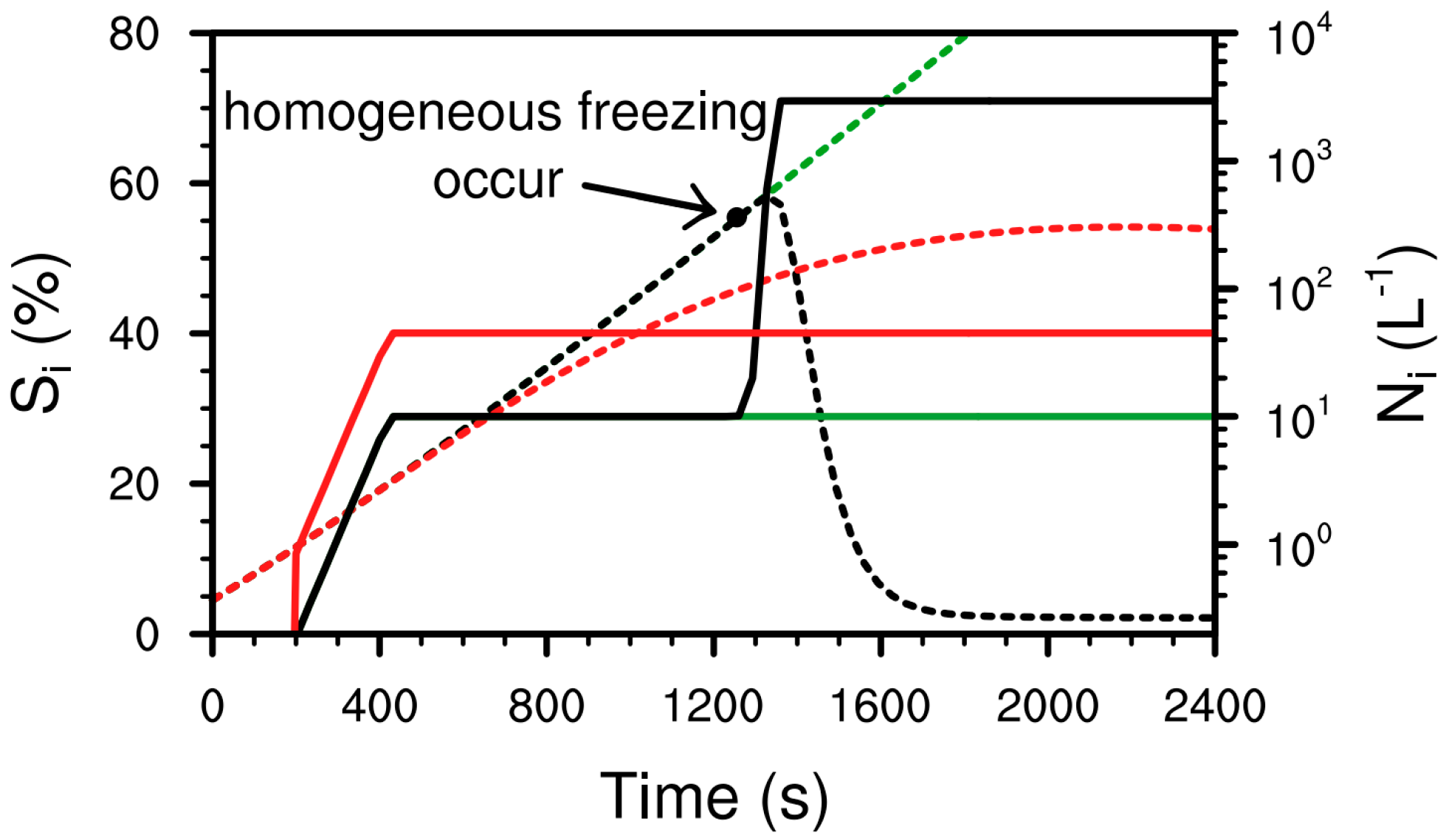
2.2. A Physically Feasible Method Used for Cirrus Thinning

Under the closed adiabatic assumption (i.e., neither thermal exchange nor mass exchange with the surrounding ambiance is possible), the change in cloud parcel Si is mainly determined by vertical velocity and ice crystal deposition/sublimation. During the rising process of Si, heterogeneous nucleation occurs earlier with the aid of ice nuclei particles. Usually, heterogeneous nucleation only produces a limited number of ice crystals (less than 100 L−1). This is primarily due to the relatively low concentration of ice nuclei particles (NINP) in the upper troposphere. Homogeneous nucleation requires relatively higher Si (Sihom usually > 50%). In other words, it is difficult to achieve homogeneous nucleation. However, homogeneous nucleation can produce a large number of ice crystals (much greater than 100 L−1) once it occurs. This is primarily due to the high concentration of soluble aerosols present in the environment [76,77]. Therefore, decreasing in-cloud ice crystal number concentration (Ni) can be achieved by preventing homogeneous nucleation from occurring [58,78]. If the ice nuclei particles can reach a certain number concentration (NINPlim, usually less than 100 L−1), the ice crystals from heterogeneous freezing could prevent Si from reaching Sihom because these newly formed ice crystals consume water vapor via deposition growth [73,79]. In other words, cirrus thinning (i.e., decreasing Ni and cloud optical depth) can be achieved by seeding with a few ice nuclei particles (NINPseed = NINPlimNINP, if NINP < NINPlim).
Figure 1 illustrates three different ice crystal formation processes from parcel model simulations. With the air parcel rising, the P of the surrounding ambiance decreases (P decreases with altitude height). The P of the air parcel is also decreased correspondingly (air parcel expands). Meanwhile, the expansion of the air parcel causes internal energy reduction, T drops, and Si increases. In the reference simulation (REF, black lines), heterogeneous nucleation produces 10 L−1 ice crystals (Ni = NINP) when Si reaches 10%. Afterward, Si is still increasing because these newly formed ice crystals are too few. Finally, homogeneous nucleation takes place (i.e., Si reaches Sihom) and produces 2937 L−1 ice crystals (much lower than Nsul, only a few parts of soluble sulfate aerosol particles freeze). The simulation in which only heterogeneous nucleation is allowed (HET, green lines) can be viewed as an idealized method of cirrus thinning, indicating the maximum potential effect of decreasing Ni (decreases to 10 L−1). In the simulation involving seeding with 35 L−1 (i.e., NINPseed) of ice nuclei particles (SEED, red lines), the 45 L−1 (i.e., NINPlim) ice crystals produced by heterogeneous freezing can prevent Si from reaching Sihom. As a result, the final Ni is still 45 L−1. It is evident that the final Ni from the SEED simulation is obviously decreased as compared to the REF simulation. Both LP and BN ice nucleation parameterizations were developed based on simulation results from similar cloud parcel models (including both homogeneous and heterogeneous nucleation, and the competition between the two pathways for ice formation in cirrus clouds). As compared to LP parameterization, one advantage of BN parameterization is that the minimum ice nuclei particle number concentration which could hinder homogeneous nucleation (i.e., NINPlim) is provided. This is the reason why the BN parameterization is implemented in CAM5.

2.3. Climate Simulation Setup

In alignment with the three parcel model simulations previously discussed, there exist three corresponding climate simulations conducted using CAM5. As compared to the REF simulation, the homogeneous nucleation is artificially deactivated in the HET simulation (i.e., pure heterogeneous nucleation). In the SEED simulation, if Ndust < NINPlim, a specific number (i.e., NINPseed) of ice nuclei particles is incorporated into the coarse-mode dust aerosols (i.e., ice nuclei particles) used to drive ice nucleation parameterization.
It is noteworthy that the changes in cirrus clouds, directly resulting from cirrus thinning, would also exert an influence on the lower mixed-phase and liquid clouds [4,32,43,80]. To enhance the analysis of how cirrus thinning affects radiative fluxes, some modifications have been made to the radiation package. Besides the default entire cloud optical depth (COD) and cloud radiative effect (CRE, the difference in the radiative fluxes between the cloud and cloud-free atmosphere), the radiation package also diagnoses COD and CRE specifically for cirrus clouds (iCOD and iCRE). Note that, iCRE is difference between the default CRE and the CRE without cirrus clouds. Meanwhile, COD and CRE from mixed-phase and liquid clouds (mlCOD and mlCRE) are calculated by subtracting iCOD from COD and iCRE from CRE. For easy reference, it is necessary to point out the rules for the abbreviations used in this study. The prefix “i” denotes that from cirrus clouds (i.e., ice clouds) and the prefix “ml” denotes that from mixed-phase and liquid clouds.
All climate simulations (i.e., REF, HET, and SEED) are atmosphere-only simulations (i.e., sea surface temperature and sea ice are given) with a horizontal resolution of 1.9° latitude × 2.5° longitude and 30 vertical layers. All simulations are executed for 11 years, and the last 10 years are used in analyses. Variability analysis of simulation results is performed using standard deviations, which are calculated based on the averages from each year.

3. Results

To facilitate communication, the symbol “Δ” is employed to represent the discrepancies (“Δ”) in relation to the REF simulation from cirrus thinning simulations (HET or SEED). If there is no special explanation, all comparative analyses are also based on the changes induced by cirrus thinning simulations. To show the source of one variable, the simulation name is added as a superscript. For example, the Ni from the REF experiment is denoted as NiREF, and ΔCODSEED indicates the COD from the SEED simulation minus that from the REF simulation. To enhance comprehension of the brightening effect induced by cirrus thinning, it is better to illustrate a comparative analysis between this brightening effect and the corresponding cooling effect. In accordance with previous studies [23,58,81], the cooling effect is quantified by anomalies in CRE at the top of the atmosphere (ΔCRETOA). Analogous to the cooling effect, the brightening effect is quantified by anomalies in CRE at the Earth’s surface (ΔCREbri). It is noteworthy that ΔCRETOA has longwave (Earth radiation) net flux (including both downward and upward irradiance) and shortwave (solar radiation) net flux (ΔCRETOAlw and ΔCRETOAsw), whereas ΔCREbri solely takes into account the component of downward solar radiation. For easy reference, it is necessary to point out that the subscript (e.g., “TOA”, “sw”, and “bri”) denotes the properties of the variable. Here, we not only demonstrate the brightening effect and cooling effect, but also place emphasis on understanding the corresponding mechanisms. These mechanisms could yield more valuable insights for leveraging the brightening effect.

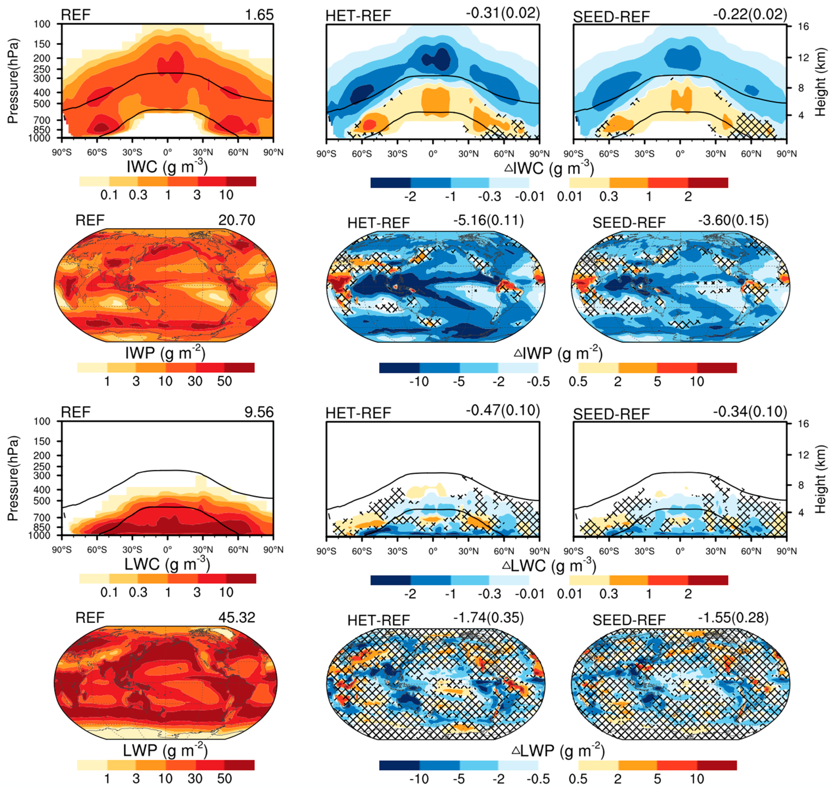
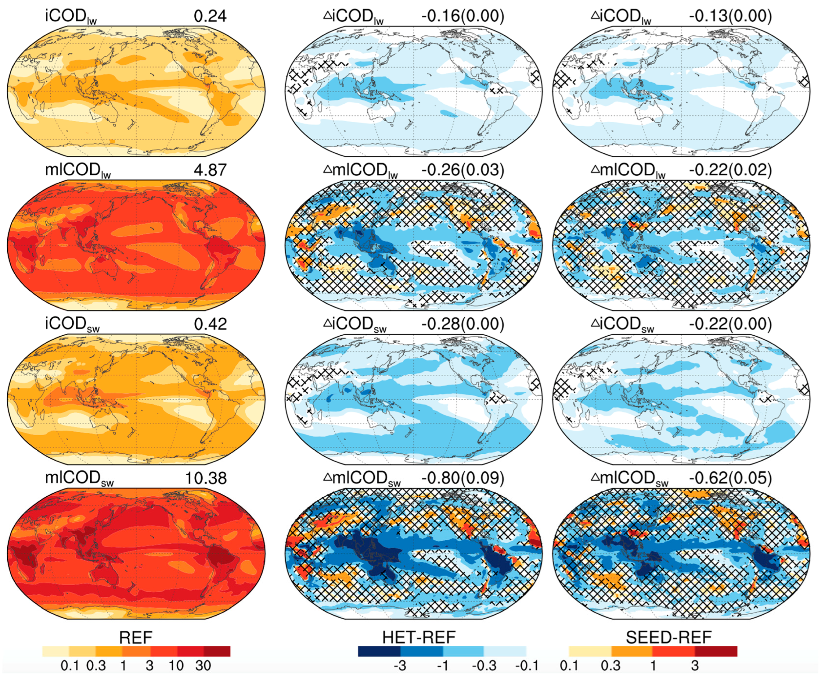
3.1. Impacts on Cloud Properties

The changes in ice crystal number concentration caused by cirrus thinning (i.e., both HET and SEED simulations) are analyzed firstly (Figure 2). After artificially turning off homogeneous freezing (i.e., HET simulation), the average number concentration of newly formed ice crystals under cirrus conditions (Ninuc) drastically decreases to a very low level (NinucHET vs. NinucREF), especially in the Southern Hemisphere where ice nuclei particles are scarce. Compared to the HET simulation (i.e., NinucHET), Ninuc is obviously increased in the SEED simulation (i.e., NinucSEED) due to seeding ice nuclei particles. However, NinucSEED is also much lower than NinucREF. In cirrus clouds, the ice crystal number concentration (i.e., Ni) is primarily influenced by the process of ice nucleation (i.e., Ninuc) [69,74]. As expected, the zonal mean Ni from both HET and SEED simulations (i.e., NiHET and NiSEED) is obviously decreased above the −37 °C isotherms (i.e., cirrus clouds). All these three simulations show that the Ni in mixed-phase clouds at mid-to-high latitudes is relatively substantial. This might be due to convective detrainment, which provides a lot of ice crystals. Because there is no homogeneous nucleation in the mixed-phase cloud scheme, neither NiHET nor NiSEED shows an obvious decrease in mixed-phase clouds. Because NiHET and NiSEED are remarkably decreased in cirrus clouds, the vertically integrated Ni (i.e., column Ni) also obviously decreases in both HET and SEED simulations. Taken overall, these cirrus thinning simulations (i.e., HET and SEED simulations) have successfully achieved their objective of remarkably reducing Ni.
The decrease in Ni (i.e., cirrus thinning) impacts not only the cloud water in cirrus clouds but also the cloud water in mixed-phase and liquid clouds (Figure 3). The ice water content (IWC) from both the HET and SEED simulations shows a notable decrease in cirrus clouds (i.e., negative ΔIWCHET and ΔIWCSEED) due to lower NiHET and NiSEED. Conversely, the positive ΔIWCHET and ΔIWCSEED in mixed-phase clouds suggest that cirrus thinning leads to an increasing IWC in mixed-phase clouds. The main reason for this might be that cirrus thinning reduces atmospheric stability through its impact on the radiation budget, thereby instigating increased convective activity, which brings more water to mixed-phase cloud layers. Another reason might be that the decrease in Ni (i.e., cirrus thinning) leads to larger ice crystals in the cirrus (not shown), and more large ice crystals (including snows) fall into mixed-phase clouds (more potent accretion of droplets by large ice crystals). The ice water path (IWP) is decreased (i.e., negative ΔIWPHET and ΔIWPSEED) in most regions because the decrease in IWC (i.e., negative ΔIWCHET and ΔIWCSEED) in cirrus clouds is stronger than the increase in IWC (i.e., positive ΔIWCHET and ΔIWCSEED) in mixed-phase clouds. It is worth noting that, in certain regions (e.g., middle Africa and northern Brazil), the IWP is increased (i.e., positive ΔIWPHET and ΔIWPSEED) because the decreases in IWC within cirrus clouds are slight (which is consistent with the slight decrease in Ni, Figure 2) and these decreases are even less strong than the increases in IWC within mixed-phase clouds there. The liquid water content (LWC) and liquid water path (LWP) are also impacted by the thinning of cirrus clouds, as shown in both HET and SEED simulations. However, these changes in LWC and LWP (i.e., ΔLWC and ΔLWP) are not as noticeable as the ΔIWC and ΔIWP. Despite the overall less noticeable changes in LWC and LWP, it is important to highlight that, in some low- and mid-latitude regions, there are obvious decreases in both LWC and LWP (i.e., negative ΔLWC and ΔLWP). Furthermore, in terms of global mean values, both LWC and LWP are also decreased (i.e., negative globally averaged ΔLWC and ΔLWP). One possible reason for this is that the larger cirrus cloud ice crystals (associated with cirrus thinning, not shown) fall into the lower mixed-phase and liquid cloud layers and enhance the efficiency of converting cloud droplets into precipitation [59,78]. Another possible reason is that cirrus thinning results in more convective activities and convective precipitation which would consume more cloud water [42,58,59,82]. The above analyses suggest that cirrus thinning also has considerable impacts on the lower mixed-phase and liquid clouds.
The changes in CRE mainly depend on the changes in cloud optical depth (COD). Figure 4 shows the changes in COD. Here, the COD in both longwave and shortwave bands (CODlw and CODsw) are shown. The COD from cirrus clouds (iCOD) is obviously decreased in both longwave and shortwave bands (iCODlw and iCODsw) over most regions (i.e., negative ΔiCODlw and ΔiCODsw). This is consistent with the decreased IWC (i.e., negative ΔIWC) in cirrus clouds (Figure 3). Furthermore, cirrus thinning (lower Ni) results in larger ice crystals (not shown), which also contribute to the decreased iCOD (i.e., opposite Twomey effect). The global mean values of iCODlw and iCODsw are decreased by more than half (i.e., ΔiCOD vs. iCOD), especially for the HET simulation. The ΔiCODlw and ΔiCODsw pass the significance test over most regions except for middle Africa and northern Brazil. Compared to ΔiCOD, the changes in COD from mixed-phase and liquid clouds (ΔmlCOD) become complicated. This is in agreement with the complex changes in cloud water within mixed-phase and liquid clouds (Figure 3). Both ΔmlCODlw and ΔmlCODsw show considerable decreases (i.e., negative values) over some low- and mid-latitude regions. In terms of global mean values, ΔmlCODlw is stronger than ΔiCODlw, and ΔmlCODsw is stronger than ΔiCODsw. In short, cirrus thinning leads to a noticeable and consistent decrease in iCOD across most regions. Additionally, it also results in a substantial decrease in mlCOD over some low- and mid-latitude regions.

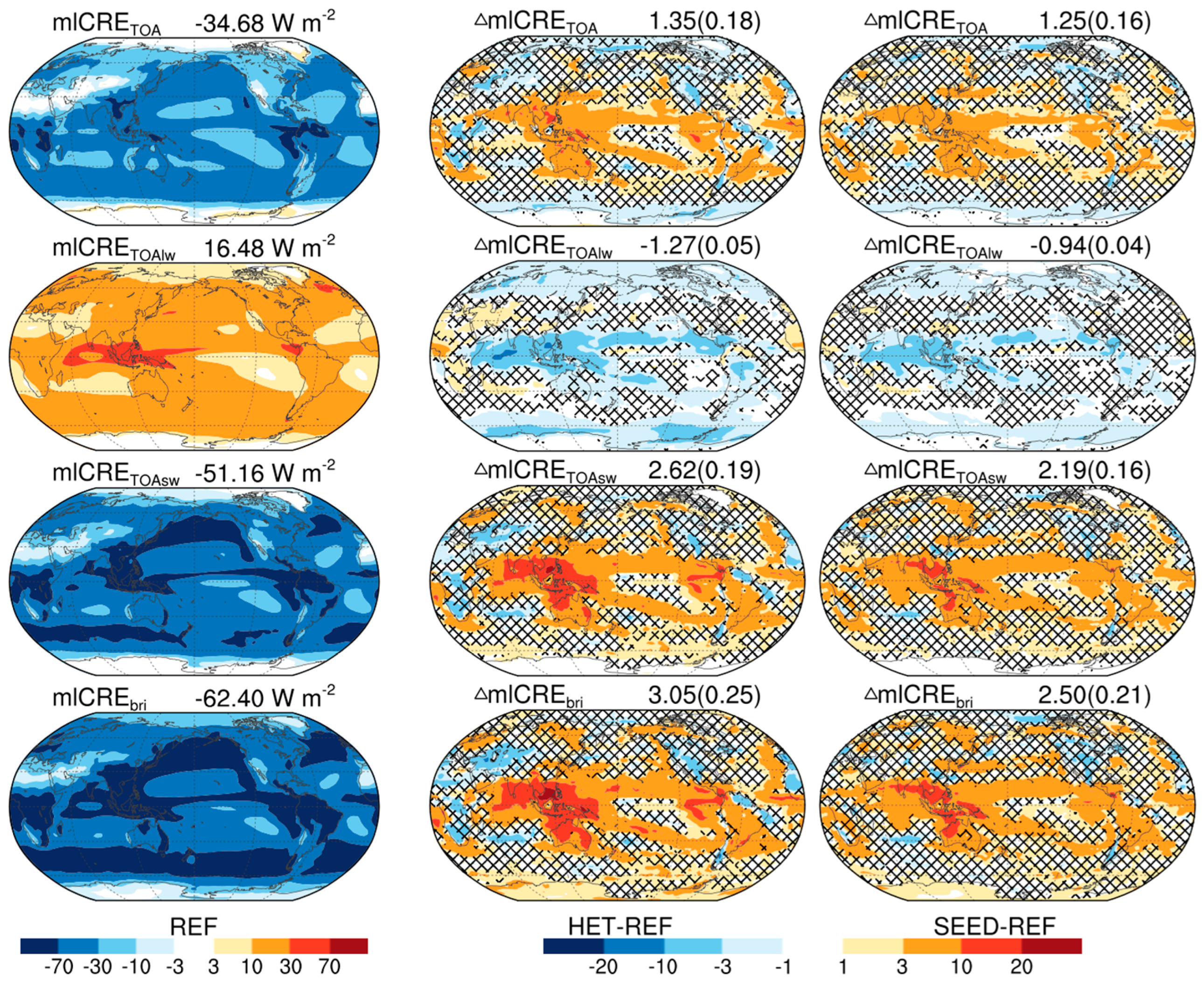
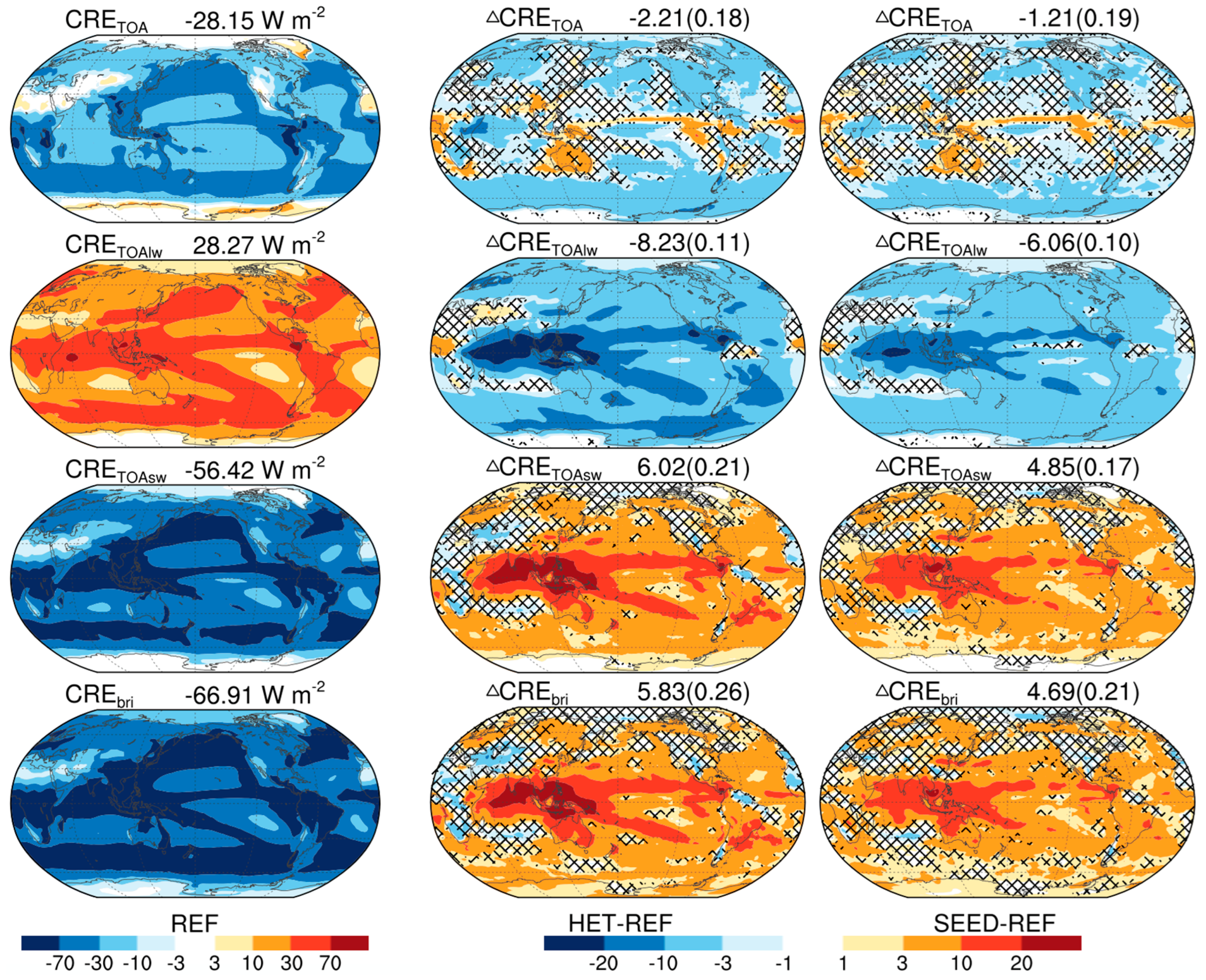
3.2. Brightening Effect and Cooling Effect

In this section, we quantify the brightening effect and cooling effect of cirrus thinning using CREbri variables (e.g., ΔCREbri and ΔmlCREbri) and CRETOA variables (e.g., ΔiCRETOA and ΔmlCRETOA), respectively. A positive value of the CREbri variables indicates a brightening effect, while a negative value suggests a dimming effect. Similarly, a negative value of the CRETOA variables signifies a cooling effect and a positive value implies a warming effect.
Firstly, we analyze the CRETOA variables and CREbri variables solely from cirrus clouds (Figure 5). The positive iCRETOAlwREF indicates that cirrus clouds warm our planet via absorbing Earth’s outgoing longwave radiation. In terms of solar radiation, the negative iCRETOAswREF indicates that cirrus clouds cool our planet. The warming effect (i.e., positive iCRETOAlwREF) is stronger than the cooling effect (i.e., absolute value of the negative iCRETOAswREF). Therefore, the globally averaged iCRETOA (iCRETOAlw + iCRETOAsw) from the REF simulation (i.e., iCRETOAREF) is 6.53 W m−2 (net warming effect). This value falls within the potential range reported in recent studies (4.5 to 6.8 W m−2) [23,32,56,80,83]. The negative iCREbriREF suggests that cirrus clouds cause a dimming effect on the Earth’s surface. The value of iCRETOAswREF (global mean is −5.26 W m−2) is a little stronger (more negative) than the value of iCREbriREF (global mean is −4.51 W m−2). Why iCRETOAswREF is a little stronger than iCREbriREF can be explained by that, in the absence of cirrus clouds, more downward solar irradiance can enter the mixed-phase and liquid cloud layers. Although the mixed-phase and liquid clouds scatter and absorb some solar radiation, most of it can reach the Earth’s surface causing a brightening effect. All these radiative fluxes (i.e., iCRETOAREF, iCRETOAlwREF, iCRETOAswREF, and iCREbriREF) show a similar spatial pattern that aligns with the COD of cirrus clouds (i.e., iCODlwREF and iCODswREF). After cirrus clouds become thin (i.e., HET and SEED simulations), the net warming effect and surface dimming effect from cirrus clouds also weaken (i.e., less positive iCRETOA and less negative iCREbri). In other words, cirrus thinning leads to cooling (i.e., negative ΔiCRETOA) and brightening (i.e., positive ΔiCREbri) effects. The globally averaged ΔiCRETOAHET and ΔiCRETOASEED are −3.56 ± 0.04 and −2.46 ± 0.04 W m−2, respectively. The globally averaged ΔiCREbriHET and ΔiCREbriSEED are 2.78 ± 0.03 and 2.19 ± 0.03 W m−2, respectively. These global mean values suggest that the cirrus cloud net warming effect (i.e., positive iCRETOA) and surface dimming effect (i.e., negative iCREbri) from the REF simulation are reduced by about half. In short, after cirrus thinning, the warming and dimming effects of cirrus clouds obviously become weaker.
Secondly, the radiative effects of mixed-phase and liquid clouds are analyzed (Figure 6). Similar to cirrus clouds, mixed-phase and liquid clouds also have a longwave warming effect (i.e., positive mlCRETOAlw) and shortwave cooling effect (i.e., negative mlCRETOAsw). As compared to cirrus clouds (iCRETOAlwREF and iCODlwREF), mlCRETOAlwREF is only increased by about half despite a roughly twenty-fold increase in mlCODlwREF. The efficiency (CRETOAlw/CODlw) of mixed-phase and liquid clouds (i.e., mlCRETOAlwREF/mlCODlwREF) is much weaker than that from cirrus clouds (i.e., iCRETOAlwREF/iCODlwREF). This is caused by the relatively small temperature difference between the Earth’s surface and these clouds (i.e., mixed-phase and liquid clouds). Unlike longwave cloud forcing (i.e., mlCRETOAlwREF), mlCRETOAswREF is approximately ten times stronger than iCRETOAswREF. Thus, the shortwave cooling effect (i.e., absolute value of negative mlCRETOAswREF) is much stronger than the longwave warming effect (i.e., positive mlCRETOAlwREF) over most regions. In terms of the sum of mlCRETOAswREF and mlCRETOAlwRE, mixed-phase and liquid clouds show a net cooling effect (i.e., negative mlCRETOAREF). Mixed-phase and liquid clouds also make the Earth’s surface dimmer (i.e., negative mlCREbriREF). Here, mlCREbriREF (downward solar irradiance at the Earth’s surface) is a little stronger (more negative) than mlCRETOAswREF (net radiative flux). The main reason for this is that a portion of mlCREbriREF (surface albedo) is reflected back into the atmosphere. Because the impact of cirrus thinning on mixed-phase and liquid clouds is complex (Figure 3 and Figure 4), the regions with statistically significant ΔmlCRE (Figure 6) are obviously smaller than ΔiCRE (Figure 5). These two cirrus thinning simulations (i.e., HET and SEED simulations) show that ΔmlCRETOAlw is generally negative (cooling effect) and ΔmlCRETOAsw is generally positive (warming effect). This is consistent with the decrease in mlCOD caused by cirrus thinning (i.e., ΔmlCOD in Figure 4). The positive ΔmlCRETOAsw is obviously stronger than the absolute value of ΔmlCRETOAlw over most low- and mid-latitude regions where solar radiation is relatively dominant. Therefore, the ΔmlCRETOA (ΔmlCRETOAlw + ΔmlCRETOAsw) values from cirrus thinning simulations are generally positive (warming effect) over there. The globally averaged ΔmlCRETOAHET and ΔmlCRETOASEED are 1.35 ± 0.18 and 1.25 ± 0.16 W m−2, respectively. The warming effect caused by the changes in mixed-phase and liquid clouds would counteract, to some extent, the cooling effect derived from the thinning of cirrus clouds alone (−3.56 ± 0.04 and −2.46 ± 0.04 W m−2, Figure 5). The globally averaged ΔmlCREbriHET and ΔmlCREbriSEED are 3.05 ± 0.25 and 2.50 ± 0.21 W m−2, respectively. The brightening effect from mixed-phase and liquid clouds is a little larger than that from cirrus clouds (ΔiCREbriHET is 2.78 ± 0.03 and ΔiCREbriSEED is 2.19 ± 0.03 W m−2). In short, after cirrus thinning, the cooling and dimming effects of mixed-phase and liquid clouds become weaker.
Finally, the brightening effect and cooling effect caused by cirrus thinning are quantified by the changes in radiative effects of entire clouds (ice, mixed-phase, and liquid clouds; Figure 7). In terms of solar radiation, the entire clouds have a globally averaged shortwave cooling effect (CRETOAswREF is −56.42 W m−2) and dimming effect (CREbriREF is −66.91 W m−2). The first two paragraphs have already shown that cirrus thinning not only causes substantial reductions in cirrus clouds’ radiative effects, but also leads to weaker radiative effects of mixed-phase and liquid clouds. As a result, the entire cloud CREs (i.e., CRETOA, CRETOAsw, CRETOAlw and CREbri) exhibit considerable reductions. The globally averaged ΔCRETOAswHET and ΔCRETOAswSEED are 6.02 ± 0.21 and 4.85 ± 0.17 W m−2, respectively. The globally averaged ΔCREbriHET and ΔCREbriSEED are 5.83 ± 0.26 and 4.69 ± 0.21 W m−2, respectively. The brightening effect (i.e., positive ΔCREbri) is close to the shortwave warming effect (positive ΔCRETOAsw), and they have a similar spatial pattern. The positive ΔCREbri values are obvious across most low- and mid-latitude regions because of the intense solar radiation present in these areas. In terms of longwave radiation, the entire clouds have a global averaged warming effect (CRETOAlwREF is 28.27 W m−2). Although the globally averaged CRETOAlwREF is roughly half of the absolute value of CRETOAswREF, ΔCRETOAlwHET and ΔCRETOAlwSEED are generally stronger than ΔCRETOAswHET and ΔCRETOAswSEED due to the dominant contribution from cirrus clouds. Therefore, in terms of the sum of shortwave and longwave radiation, both ΔCRETOAHET and ΔCRETOASEED show a cooling effect. ΔCRETOAHET and ΔCRETOASEED are −2.21 ± 0.18 and −1.21 ± 0.19 W m−2, respectively. Unlike brightening effects (ΔCREbri), these cooling effects (i.e., negative ΔCRETOA) are mainly distributed over high-latitude regions. Both HET and SEED simulations show that the brightening effect (ΔCREbri) is much stronger than the cooling effect (ΔCRETOA), especially for the SEED simulation.

4. Discussion

Compared to artificially halting homogeneous nucleation (i.e., the HET simulation) or artificially increasing the fall velocity of ice crystals (e.g., GeoMIP6), cirrus thinning via seeding of ice nuclei particles holds potential real-world feasibility. Whether there is a need to seed ice nuclei particles (i.e., if NINP < NINPlim) and the quantity of ice nuclei particles to be seeded (i.e., NINPseed) depend on the ambient atmospheric condition. The NINPseed values over different locations/times are different. Even if NINPseed has been accurately calculated, a large number of aircraft would be needed to seed these ice nuclei particles at specific times and locations. This logistical challenge presents the main barrier to the real-world feasibility of cirrus thinning. From this perspective, the SEED simulation remains largely an academic endeavor. While the quantified values of the brightening effect shown in this study are important, the analyses exploring the mechanisms behind this brightening effect (i.e., why the brightening effect caused by cirrus seeding is considerably stronger than its cooling effect) are arguably more robust and useful. These mechanism analyses could potentially contribute to future technological developments in geoengineering.

5. Conclusions

This study investigates the brightening effect caused by cirrus thinning with the CAM5 model. Here, two methods are used for cirrus thinning: artificially halting homogeneous nucleation (HET simulation) and hindering homogeneous nucleation via seeding a few ice nuclei particles (SEED simulation). As anticipated, the SEED simulation exhibits marginally diminished alterations in cloud radiative effects when compared to those from the HET simulation. Nevertheless, the underlying mechanism driving these changes remains consistent. For cirrus thinning simulations through the reduction in homogeneous nucleation, this mechanism appears to be more robust. The following conclusions drawn are based on the SEED simulation results, which possess better reference values.
After seeding ice nuclei particles, both Ninuc and Ni are obviously reduced to a very low level. The IWC of cirrus clouds is also noticeably decreased. Meanwhile, cirrus COD (both iCODlw and iCODsw) decreases by approximately half. Consequently, the net warming effect (positive iCRETOA, iCRETOA = iCRETOAlw + iCRETOAsw) and dimming effect (negative iCREbri, iCREbri is close to iCRETOAsw) from cirrus clouds are reduced by approximately half. The cooling effect (negative ΔiCRETOA) and brightening effect (positive ΔiCREbri) induced by cirrus thinning alone (i.e., only the changes in cirrus clouds) are −2.46 ± 0.04 W m−2 and 2.19 ± 0.03 W m−2, respectively. In addition, cirrus thinning also results in substantial reductions in the COD of mixed-phase and liquid clouds over some regions. Correspondingly, the net cooling effect (i.e., negative mlCRETOA) and dimming effect (i.e., negative mlCREbri, mlCREbri is close to mlCRETOAsw) from these mixed-phase and liquid clouds are also reduced. In other words, the changes within mixed-phase and liquid clouds induced by cirrus thinning lead to a globally averaged warming effect (ΔmlCRETOA, 1.25 ± 0.16 W m−2) and brightening effect (ΔmlCREbri, 2.50 ± 0.21 W m−2). The positive ΔmlCRETOA counteracts the negative ΔiCRETOA, whereas the positive ΔmlCREbri enhances the positive ΔiCREbri. Therefore, the overall brightening effect (ΔCREbri = ΔiCREbri + ΔmlCREbri, 4.69 ± 0.21 W m−2) induced by cirrus thinning is much more pronounced than its cooling effect (ΔCRETOA = ΔiCRETOA + ΔmlCRETOA, −1.21 ± 0.19 W m−2).
The spatial distribution of the brightening effect differs from that of the cooling effect due to the weakening of solar radiation at high latitudes. Cirrus thinning simulations demonstrate a considerable cooling effect (negative ΔCRETOA in Figure 7) over most high-latitude regions. This spatial distribution pattern is more conducive to mitigating the melting of polar ice caps and glaciers. Contrary to the cooling effect, the brightening effect (positive ΔCREbri in Figure 7) is considerable over most low- and mid-latitude regions. If implementing marine cloud brightening (another geoengineering approach) over the Western Pacific Warm Pool and adjacent regions, the reduction in the Earth’s surface brightness due to increased marine cloud COD could potentially be offset by the cirrus seeding approach. In short, the cirrus thinning approach possesses a unique advantage (i.e., the brightening effect) that other geoengineering approaches lack. Integrating the cirrus seeding with other geoengineering approaches could potentially enhance the cooling effect and reduce side effects [84].

Author Contributions

X.S. designed this study. X.S. and J.L. modified CAM5 model code. Y.L. carried out parcel model simulations and CAM5 simulations. X.S. and Y.L. analyzed simulation results and wrote the manuscript. All authors have read and agreed to the published version of the manuscript.

Funding

This research was funded by the National Natural Science Foundation of China (grant nos. 41775095 and 42075145). The APC was supported by the same funders.

Institutional Review Board Statement

Not applicable.

Informed Consent Statement

Not applicable.

Data Availability Statement

The Fortran code for the cloud parcel model, modified CAM5 model code, the NCL scripts, and simulation results used for making plots have been archived in a public repository (https://doi.org/10.5281/zenodo.10261111, accessed on 5 December 2023).

Acknowledgments

This study was conducted at the High-Performance Computing Center of Nanjing University of Information Science and Technology.

Conflicts of Interest

The authors declare no conflicts of interest.

References

  1. Zhang, J.C.; Zhang, K.; Liu, J.F.; Ban-Weiss, G. Revisiting the climate impacts of cool roofs around the globe using an Earth system model. Environ. Res. Lett. 2016, 11, 084014. [Google Scholar] [CrossRef]
  2. IPCC. Global Warming of 1.5 °C. An IPCC Special Report on the Impacts of Global Warming of 1.5 °C above Pre-Industrial Levels and Related Global Greenhouse Gas Emission Pathways, in the Context of Strengthening the Global Response to the Threat of Climate Change, Sustainable Development, and Efforts to Eradicate Poverty; Masson-Delmotte, V., Zhai, P., Pörtner, H.-O., Roberts, D., Skea, J., Shukla, P.R., Pirani, A., Moufouma-Okia, W., Péan, C., Pidcock, R., Eds.; Cambridge University Press: Cambridge, UK; New York, NY, USA, 2018. [Google Scholar] [CrossRef]
  3. Vaughan, N.E.; Gough, C.; Mander, S.; Littleton, E.W.; Welfle, A.; Gernaat, D.E.H.J.; van Vuure, D.P. Evaluating the use of biomass energy with carbon capture and storage in low emission scenarios. Environ. Res. Lett. 2018, 13, 044014. [Google Scholar] [CrossRef]
  4. Gruber, S.; Blahak, U.; Haenel, F.; Kottmeier, C.; Leisner, T.; Muskatel, H.; Storelvmo, T.; Vogel, B. A process study on thinning of Arctic winter cirrus clouds with high-resolution ICON-ART simulations. J. Geophys. Res. Atmos. 2019, 124, 5860–5888. [Google Scholar] [CrossRef]
  5. Kravitz, B.; MacMartin, D.G.; Visioni, D.; Boucher, O.; Cole, J.N.S.; Haywood, J.; Jones, A.; Lurton, T.; Nabat, P.; Niemeier, U.; et al. Comparing different generations of idealized solar geoengineering simulations in the Geoengineering Model Intercomparison Project (GeoMIP). Atmos. Chem. Phys. 2021, 21, 4231–4247. [Google Scholar] [CrossRef]
  6. Diamond, M.S.; Gettelman, A.; Lebsock, M.D.; McComiskey, A.; Russell, L.M.; Wood, R.; Feingold, G. To assess marine cloud brightening’s technical feasibility, we need to know what to study—And when to stop. Proc. Natl. Acad. Sci. USA 2022, 119, e2118379119. [Google Scholar] [CrossRef] [PubMed]
  7. MacMartin, D.G.; Visioni, D.; Kravitz, B.; Richter, J.H.; Felgenhauer, T.; Lee, W.R.; Morrow, D.R.; Parson, E.A.; Sugiyama, M. Scenarios for modeling solar radiation modification. Proc. Natl. Acad. Sci. USA 2022, 119, e2202230119. [Google Scholar] [CrossRef] [PubMed]
  8. Baur, S.; Nauels, A.; Nicholls, Z.; Sanderson, B.M.; Schleussner, C.-F. The deployment length of solar radiation modification: An interplay of mitigation, net-negative emissions and climate uncertainty. Earth Syst. Dynam. 2023, 14, 367–381. [Google Scholar] [CrossRef]
  9. Caldeira, K.; Bala, G.; Cao, L. The Science of Geoengineering. Annu. Rev. Earth Planet. Sci. 2013, 41, 231–256. [Google Scholar] [CrossRef]
  10. Boucher, O.; Randall, D.; Artaxo, P.; Bretherton, C.; Feingold, G.; Forster, P.; Kerminen, V.M.; Kondo, Y.; Liao, H.; Lohmann, U.; et al. Clouds and Aerosols. In Climate Change 2013: The Physical Science Basis. Contribution of Working Group I to the Fifth As-sessment Report of the Intergovernmental Panel on Climate Change; Stocker, T.F., Qin, D., Plattner, G.K., Tignor, M., Allen, S.K., Boschung, J., Nauels, A., Xia, Y., Bex, V., Midgley, P.M., Eds.; Cambridge University Press: Cambridge, UK; New York, NY, USA, 2013; pp. 571–658. [Google Scholar] [CrossRef]
  11. IPCC. Climate Change 2014: Mitigation of Climate Change. Contribution of Working Group III to the Fifth Assessment Report of the Intergovernmental Panel on Climate Change; Edenhofer, O., Pichs-Madruga, R., Sokona, Y., Farahani, E., Kadner, S., Seyboth, K., Adler, A., Baum, I., Brunner, S., Eickemeier, P., Eds.; Cambridge University Press: Cambridge, UK; New York, NY, USA, 2014. [Google Scholar] [CrossRef]
  12. Irvine, P.J.; Kravitz, B.; Lawrence, M.G.; Muri, H. An overview of the Earth system science of solar geoengineering. Wiley Interdiscip. Rev. Clim. Change 2016, 7, 815–833. [Google Scholar] [CrossRef]
  13. Cao, L. Short commentary on CMIP6 Geoengineering Model Intercomparison Project (GeoMIP). Clim. Change Res. 2019, 15, 487–492. [Google Scholar] [CrossRef]
  14. IPCC. Climate Change 2021: The Physical Science Basis. Contribution of Working Group I to the Sixth Assessment Report of the Intergovernmental Panel on Climate Change; Masson-Delmotte, V., Zhai, P., Pirani, A., Connors, S.L., Péan, C., Berger, S., Caud, N., Chen, Y., Goldfarb, L., Gomis, M.I., Eds.; Cambridge University Press: Cambridge, UK; New York, NY, USA, 2021. [Google Scholar] [CrossRef]
  15. Keller, D.P.; Lenton, A.; Scott, V.; Vaughan, N.E.; Bauer, N.; Ji, D.; Jones, C.D.; Kravitz, B.; Muri, H.; Zickfeld, K. The Carbon Dioxide Removal Model Intercomparison Project (CDRMIP): Rationale and experimental protocol for CMIP6. Geosci. Model Dev. 2018, 11, 1133–1160. [Google Scholar] [CrossRef]
  16. Minx, J.C.; Lamb, W.F.; Callaghan, M.W.; Fuss, S.; Hilaire, J.; Creutzig, F.; Amann, T.; Beringer, T.; de Oliveira Garcia, W.; Hartmann, J.; et al. Negative emissions—Part 1: Research landscape and synthesis. Environ. Res. Lett. 2018, 13, 063001. [Google Scholar] [CrossRef]
  17. Rickels, W.; Reith, F.; Keller, D.; Oschlies, A.; Quaas, M.F. Integrated Assessment of Carbon Dioxide Removal. Earth’s Future 2018, 6, 565–582. [Google Scholar] [CrossRef]
  18. Cao, L. Climate system response to carbon dioxide removal. Clim. Change Res. 2021, 17, 664–670. [Google Scholar] [CrossRef]
  19. Alterskjær, K.; Kristjánsson, J.E.; Seland, Ø. Sensitivity to deliberate sea salt seeding of marine clouds—Observations and model simulations. Atmos. Chem. Phys. 2012, 12, 2795–2807. [Google Scholar] [CrossRef]
  20. Keith, D.W.; MacMartin, D.G. A temporary, moderate and responsive scenario for solar geoengineering. Nat. Clim. Change 2015, 5, 201–206. [Google Scholar] [CrossRef]
  21. Jones, A.C.; Hawcroft, M.K.; Haywood, J.M.; Jones, A.; Guo, X.; Moore, J.C. Regional Climate Impacts of Stabilizing Global Warming at 1.5 K Using Solar Geoengineering. Earth’s Future 2018, 6, 230–251. [Google Scholar] [CrossRef]
  22. Kravitz, B.; Rasch, P.J.; Wang, H.; Robock, A.; Gabriel, C.; Boucher, O.; Cole, J.N.S.; Haywood, J.; Ji, D.; Jones, A.; et al. The climate effects of increasing ocean albedo: An idealized representation of solar geoengineering. Atmos. Chem. Phys. 2018, 18, 13097–13113. [Google Scholar] [CrossRef]
  23. Gasparini, B.; McGraw, Z.; Storelvmo, T.; Lohmann, U. To what extent can cirrus cloud seeding counteract global warming? Environ. Res. Lett. 2020, 15, 054002. [Google Scholar] [CrossRef]
  24. Cao, L. Climate system response to solar radiation modification. Clim. Change Res. 2021, 17, 671–684. [Google Scholar] [CrossRef]
  25. Vaughan, N.E.; Lenton, T.M. A review of climate geoengineering proposals. Clim. Change 2011, 109, 745–790. [Google Scholar] [CrossRef]
  26. Kravitz, B.; Robock, A.; Tilmes, S.; Boucher, O.; English, J.M.; Irvine, P.J.; Jones, A.; Lawrence, M.G.; MacCracken, M.; Muri, H.; et al. The Geoengineering Model Intercomparison Project Phase 6 (GeoMIP6): Simulation design and preliminary results. Geosci. Model. Dev. 2015, 8, 3379–3392. [Google Scholar] [CrossRef]
  27. Xin, Y. A Brief Review and Outlook of Geoengineering. Adv. Meteor. Sci. Technol. 2016, 60, 30–36. [Google Scholar] [CrossRef]
  28. Duan, L.; Cao, L.; Bala, G.; Caldeira, K. Comparison of the fast and slow climate response to three radiation management geoengineering schemes. J. Geophys. Res. Atmos. 2018, 123, 11980–12001. [Google Scholar] [CrossRef]
  29. Lawrence, M.G.; Schäfer, S.; Muri, H.; Scott, V.; Oschlies, A.; Vaughan, N.E.; Boucher, O.; Schmidt, H.; Haywood, J.; Scheffran, J. Evaluating climate geoengineering proposals in the context of the Paris Agreement temperature goals. Nat. Commun. 2018, 9, 3734. [Google Scholar] [CrossRef] [PubMed]
  30. Shepherd, J.; Caldeira, K.; Cox, P.; Haigh, J.; Keith, D.; Launder, B.; Mace, G.; MacKerron, G.; Pyle, J.; Raynor, S.; et al. Geoengineering the Climate: Science, Governance and Uncertainty; The Royal Society Publishing: London, UK, 2009; ISBN 978-0-85403-773-5. [Google Scholar]
  31. Fairbrother, M. Geoengineering, moral hazard, and trust in climate science: Evidence from a survey experiment in Britain. Clim. Change 2016, 139, 477–489. [Google Scholar] [CrossRef]
  32. Lohmann, U.; Gasparini, B. A cirrus cloud climate dial? Science 2017, 357, 248–249. [Google Scholar] [CrossRef]
  33. Heutel, G.; Moreno-Cruz, J.; Shayegh, S. Solar geoengineering, uncertainty, and the price of carbon. J. Environ. Econ. Manag. 2018, 87, 24–41. [Google Scholar] [CrossRef]
  34. Pezzoli, P.; Emmerling, J.; Tavoni, M. SRM on the table: The role of geoengineering for the stability and effectiveness of climate coalitions. Clim. Change 2023, 176, 141. [Google Scholar] [CrossRef]
  35. Naik, V.; Wuebbles, D.; DeLucia, E.; Foley, J.A. Influence of Geoengineered Climate on the Terrestrial Biosphere. Environ. Manag. 2003, 32, 373–381. [Google Scholar] [CrossRef]
  36. Robock, A.; Marquardt, A.; Kravitz, B.; Stenchikov, G. Benefits, risks, and costs of stratospheric geoengineering. Geophys. Res. Lett. 2009, 36, L19703. [Google Scholar] [CrossRef]
  37. Pitari, G.; Aquila, V.; Kravitz, B.; Robock, A.; Watanabe, S.; Cionni, I.; Luca, N.D.; Genova, G.D.; Mancini, E.; Tilmes, S. Stratospheric ozone response to sulfate geoengineering: Results from the Geoengineering Model Intercomparison Project (GeoMIP). J. Geophys. Res. Atmos. 2014, 119, 2629–2653. [Google Scholar] [CrossRef]
  38. Kleidon, A.; Kravitz, B.; Renner, M. The hydrological sensitivity to global warming and solar geoengineering derived from thermodynamic constraints. Geophys. Res. Lett. 2015, 42, 138–144. [Google Scholar] [CrossRef]
  39. Zarnetske, P.L.; Gurevitch, J.; Franklin, J.; Groffman, P.M.; Harrison, C.S.; Hellmann, J.J.; Hoffman, F.M.; Kothari, S.; Robock, A.; Tilmes, S.; et al. Potential ecological impacts of climate intervention by reflecting sunlight to cool Earth. Proc. Natl. Acad. Sci. USA 2021, 118, e1921854118. [Google Scholar] [CrossRef]
  40. Tye, M.R.; Dagon, K.; Molina, M.J.; Richter, J.H.; Visioni, D.; Kravitz, B.; Tilmes, S. Indices of extremes: Geographic patterns of change in extremes and associated vegetation impacts under climate intervention. Earth Syst. Dyn. 2022, 13, 1233–1257. [Google Scholar] [CrossRef]
  41. Jones, A.C.; Haywood, J.M.; Dunstone, N.; Emanuel, K.; Hawcroft, M.K.; Hodges, K.I.; Jones, A. Impacts of hemispheric solar geoengineering on tropical cyclone frequency. Nat. Commun. 2017, 8, 1382. [Google Scholar] [CrossRef]
  42. Kristjánsson, J.E.; Muri, H.; Schmidt, H. The hydrological cycle response to cirrus cloud thinning. Geophys. Res. Lett. 2015, 42, 10807–10815. [Google Scholar] [CrossRef]
  43. Liu, J.; Shi, X. Estimating the potential cooling effect of cirrus thinning achieved via the seeding approach. Atmos. Chem. Phys. 2021, 21, 10609–10624. [Google Scholar] [CrossRef]
  44. Pongratz, J.; Lobell, D.B.; Cao, L.; Caldeira, K. Crop yields in a geoengineered climate. Nat. Clim. Change 2012, 2, 101–105. [Google Scholar] [CrossRef]
  45. Xia, L.; Robock, A.; Cole, J.; Curry, C.L.; Ji, D.; Jones, A.; Kravitz, B.; Moore, J.C.; Muri, H.; Niemeier, U.; et al. Solar radiation management impacts on agriculture in China: A case study in the Geoengineering Model Intercomparison Project (GeoMIP). J. Geophys. Res. Atmos. 2014, 119, 8695–8711. [Google Scholar] [CrossRef]
  46. Parkes, B.; Challinor, A.; Nicklin, K. Crop failure rates in a geoengineered climate: Impact of climate change and marine cloud brightening. Environ. Res. Lett. 2015, 10, 084003. [Google Scholar] [CrossRef]
  47. Zhan, P.; Zhu, W.Q.; Zhang, T.Y.; Cui, X.F.; Li, N. Impacts of sulfate geoengineering on rice yield in China: Results from a multimodel ensemble. Earth’s Future 2019, 7, 395–410. [Google Scholar] [CrossRef]
  48. Fan, Y.; Tjiputra, J.F.; Muri, H.; Lombardozzi, D.L.; Park, C.; Wu, S.; Keith, D. Solar geoengineering can alleviate climate change pressures on crop yields. Nat. Food 2021, 2, 373–381. [Google Scholar] [CrossRef]
  49. Kravitz, B. Effects of climate engineering on agriculture. Nat. Food 2021, 2, 320–321. [Google Scholar] [CrossRef]
  50. Proctor, J. Atmospheric opacity has a nonlinear effect on global crop yields. Nat. Food 2021, 2, 166–173. [Google Scholar] [CrossRef]
  51. Wanser, K.; Doherty, S.J.; Hurrell, J.W.; Wong, A. Near-term climate risks and solar radiation modification: A roadmap approach for physical sciences research. Clim. Change 2022, 174, 23. [Google Scholar] [CrossRef]
  52. Cassidy, M.; Sandberg, A.; Mani, L. The ethics of volcano geoengineering. Earth’s Future 2023, 11, e2023EF003714. [Google Scholar] [CrossRef]
  53. Kortetmäki, T.; Oksanen, M. Right to Food and Geoengineering. J. Agric. Environ. Ethics 2023, 36, 5. [Google Scholar] [CrossRef]
  54. McDonald, M. Geoengineering, climate change and ecological security. Environ. Polit. 2023, 32, 565–585. [Google Scholar] [CrossRef]
  55. Berry, E.; Mace, G.G. Cloud properties and radiative effects of the Asian summer monsoon derived from A-Train data. J. Geophys. Res. Atmos. 2014, 119, 9492–9508. [Google Scholar] [CrossRef]
  56. Hong, Y.; Liu, G.; Li, J.F. Assessing the Radiative Effects of Global Ice Clouds Based on CloudSat and CALIPSO Measurements. J. Clim. 2016, 29, 7651–7674. [Google Scholar] [CrossRef]
  57. Matus, A.V.; L’Ecuyer, T.S. The role of cloud phase in Earth’s radiation budget. J. Geophys. Res. Atmos. 2017, 122, 2559–2578. [Google Scholar] [CrossRef]
  58. Storelvmo, T.; Herger, N. Cirrus cloud susceptibility to the injection of ice nuclei in the upper troposphere. J. Geophys. Res. Atmos. 2014, 119, 2375–2389. [Google Scholar] [CrossRef]
  59. Gasparini, B.; Münch, S.; Poncet, L.; Feldmann, M.; Lohmann, U. Is increasing ice crystal sedimentation velocity in geoengineering simulations a good proxy for cirrus cloud seeding? Atmos. Chem. Phys. 2017, 17, 4871–4885. [Google Scholar] [CrossRef]
  60. Ji, D.; Fang, S.; Curry, C.L.; Kashimura, H.; Watanabe, S.; Cole, J.N.S.; Lenton, A.; Muri, H.; Kravitz, B.; Moore, J.C. Extreme temperature and precipitation response to solar dimming and stratospheric aerosol geoengineering. Atmos. Chem. Phys. 2018, 18, 10133–10156. [Google Scholar] [CrossRef]
  61. Liu, J. Cooling the earth and brightening the surface by cirrus thinning geoengineering. In Proceedings of the GeoMIP Meeting, Online, 29 June 2020. [Google Scholar]
  62. Duan, L.; Cao, L.; Bala, G.; Caldeira, K. A model-based investigation of terrestrial plant carbon uptake response to four radiation modification approaches. J. Geophys. Res. Atmos. 2020, 125, e2019JD031883. [Google Scholar] [CrossRef]
  63. Mercado, L.; Bellouin, N.; Sitch, S.; Boucher, O.; Huntingford, C.; Wild, M.; Cox, P.M. Impact of changes in diffuse radiation on the global land carbon sink. Nature 2009, 458, 1014–1017. [Google Scholar] [CrossRef]
  64. Wild, M.; Roesch, A.; Ammann, C. Global dimming and brightening—Evidence and agricultural implications. CABI Rev. 2012, 7, 1–7. [Google Scholar] [CrossRef]
  65. Yang, H.Y.; Dobbie, S.; Ramirez-Villegas, J.; Feng, K.; Challinor, A.J.; Chen, B.; Gao, Y.; Lee, L.; Yin, Y.; Sun, L.X.; et al. Potential negative consequences of geoengineering on crop production: A study of Indian groundnut. Geophys. Res. Lett. 2016, 43, 11786–11795. [Google Scholar] [CrossRef]
  66. Proctor, J.; Hsiang, S.; Burney, J.; Burke, M.; Schlenker, W. Estimating global agricultural effects of geoengineering using volcanic eruptions. Nature 2018, 560, 480–483. [Google Scholar] [CrossRef]
  67. Meng, Q.; Liu, B.; Yang, H.; Chen, X. Solar dimming decreased maize yield potential on the North China Plain. Food Energy Secur. 2020, 9, e235. [Google Scholar] [CrossRef]
  68. Pruppacher, H.; Klett, J. Microphysics of Clouds and Precipitation; Atmospheric and Oceanographic Sciences Library; Springer: Dordrecht, The Netherland, 2010; Volume 18. [Google Scholar] [CrossRef]
  69. Shi, X.; Liu, X. Effect of cloud-scale vertical velocity on the contribution of homogeneous nucleation to cirrus formation and radiative forcing. Geophys. Res. Lett. 2016, 43, 6588–6595. [Google Scholar] [CrossRef]
  70. Neale, R.B.; Gettelman, A.; Park, S.; Chen, C.-C.; Lauritzen, P.H.; Williamson, D.L.; Conley, A.J.; Kinnison, D.; Marsh, D.; Smith, A.K.; et al. Description of the NCAR Community Atmosphere Model (CAM 5.0); NCAR/TN-486+STR; National Center for Atmospheric Research: Boulder, CO, USA, 2012. [Google Scholar] [CrossRef]
  71. Morrison, H.; Gettelman, A. A New Two-Moment Bulk Stratiform Cloud Microphysics Scheme in the Community Atmosphere Model, Version 3 (CAM3). Part I: Description and Numerical Tests. J. Clim. 2008, 21, 3642–3659. [Google Scholar] [CrossRef]
  72. Liu, X.; Penner, J.E. Ice nucleation parameterization for global models. Meteorol. Z. 2005, 14, 499–514. [Google Scholar] [CrossRef]
  73. Barahona, D.; Nenes, A. Parameterizing the competition between homogeneous and heterogeneous freezing in ice cloud formation—Polydisperse ice nuclei. Atmos. Chem. Phys. 2009, 9, 5933–5948. [Google Scholar] [CrossRef]
  74. Shi, X.; Liu, X.; Zhang, K. Effects of pre-existing ice crystals on cirrus clouds and comparison between different ice nucleation parameterizations with the Community Atmosphere Model (CAM5). Atmos. Chem. Phys. 2015, 15, 1503–1520. [Google Scholar] [CrossRef]
  75. Shi, X.; Liu, X. Sensitivity study of anthropogenic aerosol indirect forcing through cirrus clouds with CAM5 using three ice nucleation parameterizations. J. Meteorol. Res. 2018, 32, 693–706. [Google Scholar] [CrossRef]
  76. Lohmann, U.; Spichtinger, P.; Jess, S.; Peter, T.; Smit, H. Cirrus cloud formation and ice supersaturated regions in a global climate model. Environ. Res. Lett. 2008, 3, 045022. [Google Scholar] [CrossRef]
  77. Kärcher, B.; Lohmann, U. A parameterization of cirrus cloud formation: Homogenous freezing of supercooled aerosols. J. Geophys. Res. 2002, 107, 4010. [Google Scholar] [CrossRef]
  78. Storelvmo, T.; Kristjansson, J.E.; Muri, H.; Pfeffer, M.; Barahona, D.; Nenes, A. Cirrus cloud seeding has potential to cool climate. Geophys. Res. Lett. 2013, 40, 178–182. [Google Scholar] [CrossRef]
  79. Hoose, C.; Möhler, O. Heterogeneous ice nucleation on atmospheric aerosols: A review of results from laboratory experiments. Atmos. Chem. Phys. 2012, 12, 9817–9854. [Google Scholar] [CrossRef]
  80. Gasparini, B.; Lohmann, U. Why cirrus cloud seeding cannot substantially cool the planet. J. Geophys. Res. Atmos. 2016, 121, 4877–4893. [Google Scholar] [CrossRef]
  81. Mitchell, D.L.; Finnegan, W. Modification of cirrus clouds to reduce global warming. Environ. Res. Lett. 2009, 4, 045102. [Google Scholar] [CrossRef]
  82. Rapp, A.D.; Kummerow, C.D.; Fowler, L. Interactions between warm rain clouds and atmospheric preconditioning for deep convection in the tropics. J. Geophys. Res. Atmos. 2011, 116, D23210. [Google Scholar] [CrossRef]
  83. Muench, S.; Lohmann, U. Developing a cloud scheme with prognostic cloud fraction and two moment microphysics for ECHAM-HAM. J. Adv. Model. Earth Syst. 2020, 12, e2019MS001824. [Google Scholar] [CrossRef]
  84. Cao, L.; Duan, L.; Bala, G.; Caldeira, K. Simultaneous stabilization of global temperature and precipitation through cocktail geoengineering. Geophys. Res. Lett. 2017, 44, 7429–7437. [Google Scholar] [CrossRef]
Figure 1. Schematic diagram of cirrus thinning methods. Shown are the reference simulation without seeding (REF, black), seeding ice nuclei particles simulation (SEED, red), and only heterogeneous nucleation simulation (HET, green). The ice supersaturation (Si, units: %) and number concentration of ice crystals (Ni, units: L−1) in the air parcel are represented by dashed and solid lines, respectively. All simulations start with common initial conditions (NINP = 10 L−1, Nsul = 500,000 L−1, P = 330 hPa, T = 220 K, and W = 0.3 m s−1).
Atmosphere 15 00189 g001
Figure 2. Annual zonal mean of newly formed ice crystal number concentration in cirrus clouds (Ninuc, first row) and in-cloud ice crystal number concentration (Ni, second row), and spatial distributions of vertically integrated Ni (column Ni, third row). Simulation names and globally averaged values are displayed at the top. The zonal mean results are derived from model grids where the occurrence frequency of corresponding events is greater than 0.1%. The two black lines denote specific temperatures (0 and −37 °C).
Atmosphere 15 00189 g002
Figure 3. Annual zonal mean ice water content (IWC, first row) and spatial distribution of ice water path (IWP, second row). The third and fourth rows respectively denote the liquid water content (LWC) and the ice water path (IWP). The first column displays the REF simulation, while the second and third columns represent the discrepancies (“Δ”) in relation to the REF simulation from both HET and SEED simulations. Global mean values and corresponding standard deviations (in brackets) are shown in the upper right corner. Hatching represents the nonsignificant area at the 90% confidence level of t-test.
Atmosphere 15 00189 g003
Figure 4. Annual mean maps of cirrus cloud optical depth in longwave band (iCODlw, first row) and shortwave band (iCODsw, third row), and optical depth from mixed-phase and liquid clouds in long-wave band (mlCODlw, second row) and short-wave band (mlCODsw, fourth row). Global mean values and corresponding standard deviations (in brackets) are shown in the upper right corner. Hatching represents the nonsignificant area at the 90% confidence level of t-test.
Atmosphere 15 00189 g004
Figure 5. Annual mean maps of cirrus cloud radiative effect (iCRETOA, first row), its longwave (iCRETOAlw, second row) and shortwave (iCRETOAsw, third row) components, and brightness radiative effect (iCREbri, fourth row). Global mean values and corresponding standard deviations (in brackets) are shown in the upper right corner. Hatching represents the nonsignificant area at the 90% confidence level of t-test.
Atmosphere 15 00189 g005
Figure 6. Similar to Figure 5, but for mixed-phase and liquid cloud radiative effects (mlCRETOA, mlCRETOAlw, mlCRETOAsw, and mlCREbri).
Atmosphere 15 00189 g006
Figure 7. Similar to Figure 5, but for the entire clouds’ (ice, mixed-phase, and liquid) radiative effect (CRETOA, CRETOAlw, CRETOAsw, and CREbri).
Atmosphere 15 00189 g007
Disclaimer/Publisher’s Note: The statements, opinions and data contained in all publications are solely those of the individual author(s) and contributor(s) and not of MDPI and/or the editor(s). MDPI and/or the editor(s) disclaim responsibility for any injury to people or property resulting from any ideas, methods, instructions or products referred to in the content.

