Article

Development of High-Precision Local and Regional Ionospheric Models Based on Spherical Harmonic Expansion and Global Navigation Satellite System Data in Serbia

by
Dušan Petković
1,*,
Oleg Odalović
1,
Aleksandra Nina
2,
Miljana Todorović-Drakul
1,
Aleksandra Kolarski
2,
Sanja Grekulović
1 and
Stefan Krstić
1
1
Faculty of Civil Engineering, University of Belgrade, 11000 Belgrade, Serbia
2
Institute of Physics Belgrade, University of Belgrade, 11080 Belgrade, Serbia
*
Author to whom correspondence should be addressed.
Atmosphere 2025, 16(5), 496; https://doi.org/10.3390/atmos16050496
Submission received: 20 March 2025 / Revised: 12 April 2025 / Accepted: 23 April 2025 / Published: 25 April 2025
(This article belongs to the Special Issue GNSS Remote Sensing in Atmosphere and Environment (2nd Edition))

Abstract

:
The relationship between ionospheric research and global navigation satellite systems (GNSS) can be analysed through two approaches. The direct approach utilises ionospheric models to mitigate its influence, while the indirect approach leverages GNSS data to model ionospheric parameters. This study presents an indirect approach in which the total electron content (TEC), a fundamental parameter for ionospheric conditions, is modelled as a harmonic function using spherical harmonic (SH) expansion. Station-specific (local) and regional ionospheric models are developed by decomposing ionospheric influence into deterministic and stochastic components. GNSS data from seven evenly distributed stations in Serbia were used to estimate TEC coefficients. Local models were provided in the ION format as SH coefficients, allowing TEC determination at any epoch, while regional models had a 0.5 × 0.5 spatial and 2 h temporal resolution. The TEC root mean square (RMS) values ranged from 0.2 to 0.5 TECU (total electron content unit), with a mean of 0.3 TECU. Validation against global ionospheric maps showed agreement within 5.0 TECU. The impact of the SH expansion degree and order on TEC values was also analysed. These results refine regional ionospheric modelling, improving GNSS positioning accuracy in Serbia and beyond.

1. Introduction

The ionosphere is one of the Earth’s atmosphere layers, extending from approximately 50 km to over 1000 km in altitude [1,2]. It is characterised by the presence of free electrons and ions, which are primarily generated through ionisation caused by solar radiation. Due to its unique electrical properties, the ionosphere plays a crucial role in communications and radio wave propagation [3]. Considering radio wave (e.g., satellite signals) propagation, the ionosphere can be described as a highly inhomogeneous, anisotropic, and dispersive medium [4].
A fundamental parameter used to describe ionospheric conditions is the electron density, representing the number of free electrons per unit volume. Electron density is not uniform across the ionosphere and varies with altitude, forming distinct ionospheric regions (layers) [1,2,3]:
  • The D-region exists at lower altitudes (from 50 km to 90 km) only during daytime and exhibits weak ionisation. The influence of the D-region is generally considered negligible. However, during the solar cycle maximum and periods of maximum perturbations of electron concentration caused by solar X flares, the influence is not insignificant [5];
  • The E-region (from 90 km to 140 km) represents an intermediate region with moderate ionisation, present both during the day and partially at night. Compared to the higher regions, the E-region is weakly ionised. Although partially present at night, this region has a minor effect on radio waves, compared to higher ones;
  • The F-region (from 140 km to 1000 km) contains the highest concentration of electrons and is the most significant for radio wave propagation [6]. During the day, the F-region splits into the F1 and F2 regions. The F2 is the most significant cause of delay in satellite signals and is the most critical for navigation and space communication. A high variability rate also characterises this region in time, so it is difficult to predict its impact. It is present both during the day and during the night [7].
The ionosphere is a very complex and highly dynamic region of the Earth’s atmosphere, characterised by a high degree of variability. One of the key challenges in ionospheric research is the accurate modelling of the total electron content (TEC) as a key measurable quantity, representing the integral electron density along the signal path between a transmitter and a receiver. The TEC is expressed in total electron content units (TECU), where 1 TECU corresponds to 10 16 free electrons per square meter [7,8].
Ionosphere studies and research are essential for various scientific and technological applications. Since the 1960s, an international project sponsored by the Committee on Space Research (COSPAR) and the International Union of Radio Science (URSI) named International Reference Ionosphere (IRI) was released in order to produce an empirical standard model of the ionosphere [9,10]. Throughout the years, several IRI models have been released, as new data became available, such as IRI 2000 [11], IRI 2012 [12], IRI 2016 [13] and IRI 2020 [14]. Besides the IRI model, the empirical ionospheric model NeQuick can also be highlighted [10]. The NeQuick model is developed at the T-ICT4D Department of The Abdus Salam International Centre for Theoretical Physics (ICTP), Trieste, Italy, and at the Institute for Geophysics, Astrophysics, and Meteorology (IGAM) of the University of Graz, Austria. NeQuick is based on the model introduced originally by Di Giovanni and Radicella (DGR model) [15], and several versions have been introduced throughout the years of development [16,17,18]. It is important to note that the International Telecommunication Union (ITU) adopted NeQuick for TEC estimation [10]. Additionally, the special version NeQuick-G implemented by the European Space Agency (ESA) has been adopted as the Galileo single-frequency ionospheric correction algorithm [10,19,20].
In addition to global and empirical modelling, ionospheric conditions have traditionally been investigated through ionosonde measurements [21,22,23,24,25], providing valuable insights into electron density variability and the temporal dynamics of ionospheric regions. Moreover, investigations of lower ionospheric layers, particularly the D-region, frequently utilise very-low-frequency (VLF) and low-frequency (LF) signals [26,27,28]. Analysing amplitude and phase variations in VLF/LF signals enables effective detection and characterisation of electron density perturbations induced by solar and other external factors.
Global navigation satellite systems (GNSS), such as GPS (Global Positioning System), GLONASS (Globalnaya Navigationnaya Sputnikovaya Sistema), Galileo, and BeiDou [29], rely heavily on precise ionospheric modelling due to the significant impact of ionospheric electron content on signal propagation. Variations in the ionosphere directly affect GNSS signal delays [6,7,8], positioning accuracy, and overall system reliability, making ionospheric research fundamental for advancing satellite navigation technologies.
The utility of ionospheric models is reflected in their use in many processes and algorithms within data processing (for example, when resolving integer carrier-phase ambiguity) [30]. Additionally, model usage in GNSS data processing can be significant, taking into account the advantage of single-frequency data processing in combination with ionospheric models over dual-frequency data processing in the case of relatively small areas (about 10 km) [6]. Considering the aforementioned, the determination of reliable ionospheric models has a key role and great importance as well.
Contrary to what has been mentioned, the dispersive property of the ionosphere provides GNSS positioning with great potential for ionospheric research, i.e., ionospheric model determination [8,30]. By using dual-frequency data, one can either eliminate the ionospheric effect (the most significant part of it) or extract (isolate) it to preserve the amount of effect and finally derive the TEC.
Many studies and research efforts have been dedicated to the approaches mentioned above. One of the foundational contributions was made by Klobuchar, who introduced an empirical ionospheric correction algorithm known as the Klobuchar model. This model is designed for single-frequency GPS users, effectively reducing ionospheric delay by approximating electron content variability using a simplified cosine-based representation [31].
During the last decade of the 20th century, several significant advancements were made in ionospheric modelling and GNSS technologies. For instance, one notable study [32] introduced a TEC representation based on geometry-free linear combination observables and Taylor series expansions. Another important contribution [33] utilised GPS-derived TEC data to enhance the performance of global ionospheric models. A substantial step forward was presented by the research [6,34,35] which clearly defined the concept of global, regional, and station-specific ionospheric models, representing the TEC through spherical harmonic functions.
Other research [4] further contributed by developing methodologies for modelling and predicting the ionospheric TEC specifically tailored for high-precision differential GNSS applications. This study also introduced a recursive physics-based model capturing regular TEC variations, along with an algorithm for real-time modelling of medium-scale travelling ionospheric disturbances (TIDs).
Within the International GNSS Service (IGS) framework, the Ionosphere Working Group has been generating combined global ionospheric maps (GIMs) since 1998 [36]. These maps are produced by integrating independent GIMs, regularly calculated by eight designated IGS Ionosphere Associate Analysis Centers. Currently, the primary products provided by the IGS Ionosphere Working Group include final, rapid, real-time, and predicted (1- and 2-day-ahead) IGS GIMs, along with IGS TEC fluctuation maps [37]. Significant publications associated with the activities of the IGS Ionosphere Working Group encompass several comprehensive studies [38,39,40,41,42].
In general, it can be said that the relationship between ionospheric research and GNSS can be analysed through two approaches:
  • The direct approach, which utilises existing ionospheric models to minimise their impact on GNSS positioning and support other aspects of data processing;
  • The indirect approach, which leverages GNSS observations to estimate ionospheric parameters and develop ionospheric models.
Thus, the GNSS technology not only benefits from ionospheric modelling advancements, but also actively contributes to a better understanding and characterisation of ionospheric conditions.
To the best of our knowledge, significant ionospheric research in Serbia has been carried out, focusing particularly on modelling the ionospheric influence on GPS signals within network RTK (real-time kinematic) environments [43]. Additionally, one study [44] showed noticeable variations in the D-region electron content during the activity of a solar X-ray flare, when the D-region’s TEC contribution to the TEC could reach several percent, which cannot be neglected. Finally, another study [45] was dedicated to modelling extreme TEC values in the territory of Serbia based on machine learning techniques. For the extreme TEC values, maximum values from the peak of the 11-year cycle of solar activity in the years 2013, 2014, and 2015 for the days of the winter and summer solstice and autumnal and vernal equinox were considered. GNSS observations from three permanent stations in Serbia were used to inspect the possibility of using machine learning techniques. Considering the Balkan Peninsula region, we can highlight a study [46] that presented the development of regional ionosphere models in several countries in the western Balkans based on dense GNSS observations and using an artificial neural network that combined regional ionosphere parameters estimated from the GNSS data with spatiotemporal, solar, and geomagnetic parameters.
Considering that GNSS-based methods are among the most effective ways to model ionospheric parameters, this study followed the indirect approach, in which the TEC is modelled as a spherical harmonic (SH) function to develop local and regional ionospheric models. The modelling process involved decomposing ionospheric effects into deterministic and stochastic components [6,30], allowing for a more precise representation of ionospheric variability. A dataset of GNSS observations from seven GNSS stations in Serbia was used to estimate SH expansion coefficients, enabling the development of station-specific and regional models. The station-specific models were determined for each GNSS station and stored in the ION format, facilitating TEC determination at any epoch. Unlike station-specific (local) ionospheric models, the determination of regional ionospheric models was performed by an estimation of the unique set of SH coefficients for the desired territory, with a spatial resolution of 0.5 × 0.5 and a temporal resolution of 2 h, provided in both the ION and IONEX (Ionosphere Map Exchange) formats [47,48].
This study, to the best of our knowledge, is the first to develop both local and regional ionospheric models for the territory of the Republic of Serbia using spherical harmonic expansion. The novelty of the approach lies in the exclusive use of GNSS observations from a network of stations located entirely within Serbia, without incorporating data from the regional or global GNSS infrastructure. This strategy allows for the assessment of how reliably a local GNSS infrastructure alone can support TEC modelling over a limited geographic area. Although publicly available IGS stations in neighbouring countries could offer a broader coverage, the chosen approach highlights the feasibility of creating high-precision ionospheric products using only local data. This has practical relevance, especially considering that no GNSS station from Serbia currently contributes to the computation of global ionospheric maps. Therefore, the presented methodology offers a foundation for integrating locally derived TEC products into GNSS data processing workflows and potentially enhancing the modelling of ionospheric conditions at the national and regional levels.
Spherical harmonic expansion remains a widely used and powerful approach in ionospheric modelling due to its capability to describe large-scale TEC variations with a compact set of coefficients. Several studies have demonstrated the application of SH-based methods across different spatial scales and methodological focuses. For instance, global TEC mapping based on the phase difference approach and truncated SH expansion was presented in one study [49], eliminating the need for DCB estimation and implementing the least squares technique with constraints. Multi-GNSS global ionospheric maps were developed in one study [50] using SH expansion up to degree 15, while another study [51] investigated different estimation schemes and configurations for SH modelling under moderate solar activity. A broader global model was also proposed in one study [52], using over 100 GPS stations to produce hourly TEC maps. Importantly, local and regional applications of SH-based models were also reported. A TEC model over Pakistan using only a local GNSS network and SH expansion was developed in one study [53], achieving a better agreement with regional observations than with global models. One study [54] applied spherical harmonic analysis to TEC modelling across the Arctic region, while another study [55] combined an artificial neural network and SH modelling to construct regional TEC maps for Australia based on dense GNSS coverage. Another study [56] evaluated regional TEC mapping in China using SH modelling. These works confirm that SH-based approaches are suitable for global, regional, and local applications and support the development of locally adapted models such as the one presented in this study.

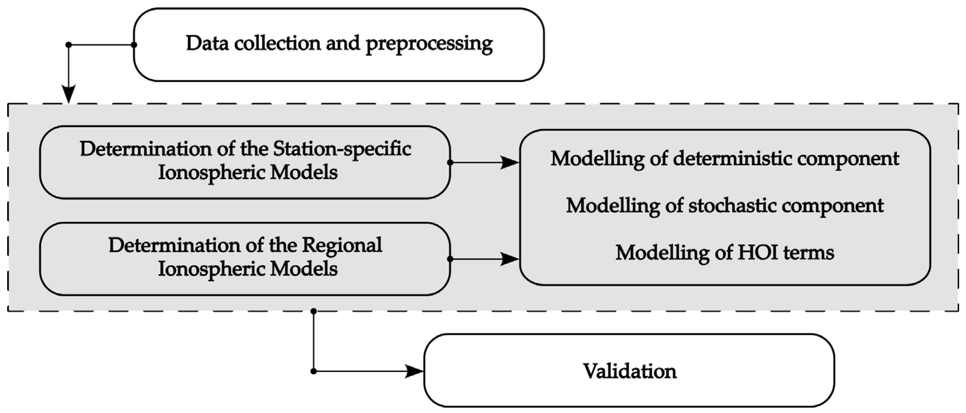
2. Data and Methodology

This chapter presents the data sources and basic methodology used in this study. Section 2.1 provides the mathematical background, outlining the fundamental equations and the TEC spherical harmonic expansion, and Section 2.2 describes the study area and details the data collection process, including the selection and distribution of GNSS stations across Serbia. The methodological approach for the local and regional ionospheric modelling and the validation techniques applied to assess model accuracy are also introduced.

2.1. Mathematical Background

This section briefly presents the mathematical foundation of the conducted research. First, it is necessary to define the fundamental observables in GNSS positioning: code pseudoranges and carrier phase measurements. In GNSS positioning, the primary measurements are based on code and carrier phase observations, both of which are affected by various sources of error. The fundamental equation describing code pseudoranges P can be expressed as follows [7,8,30,57]:
P R S t f = ρ R S + c 0 Δ t R c 0 Δ t S + Δ ρ I o n o + Δ ρ T r o p + Δ ρ M . P a t h + Δ ρ E p h + Δ ρ R e s + ε P ,
and for phase pseudoranges L :
L R S t f = ρ R S + c 0 Δ t R c 0 Δ t S Δ ρ I o n + Δ ρ T r o p + Δ ρ M . P a t h + Δ ρ E p h + Δ ρ R e s + ε L + λ N R S ,
where ρ R S denotes the geometric distance between satellite S and receiver R , Δ t R and Δ t S represent the errors of the receiver and satellite clock, ε denotes the random measurement error part, while Δ ρ terms represent the various sources of errors caused by (in the order of appearance in the equations) ionosphere, troposphere, multi-path, and ephemerides. Specifically, Δ ρ R e s represents all other unmodelled effects (which is often joined to a random measurement error term ε ), while λ N denotes the integer carrier phase ambiguity (where λ is the carrier wavelength and N is the unknown integer number of full carrier cycles between the satellite and the receiver). Terms c 0 and f denote the speed of light and the observed frequency. For readability, explicit time and frequency dependencies are omitted in the above equations.
In addition to the presented equations, ionospheric GNSS determination relies on two fundamental data processing concepts: difference formation and linear combination of dual-frequency data. Based on the notation in the previous equations, for receivers i and j observing satellites m and n , we defined a total of 8 equations—4 for code pseudoranges and 4 for phase pseudoranges, at observed frequency f within a single epoch t . Such a set of equations (non-differentiated) is often referred to in the literature as zero-difference equations [6,30].
The first level of differentiation concept, the so-called single differences, are defined as the difference between the pseudoranges from receivers i and j to satellite m [7,8]:
L i , j m t f = L i m t f L j m t f = ρ i , j m + c 0 ( Δ t i Δ t j ) Δ ρ i , j m I o n o + ε L i , j m + λ N i , j m ,
where we can eliminate satellite clock errors Δ t m , while the other model members now refer to differentiated values. It is important to note that, due to simplicity, the model’s terms that refer to troposphere, multi-path, and satellite ephemerides are included in the random noise part. By applying single differencing, the impact of these error sources is significantly reduced or even eliminated, particularly for receivers that are geographically close and at similar elevations. Further details can be found in [7].
The second level of differentiation, known as double differences, is defined as the difference between the single differences formed for receivers i and j while observing satellites m and n :
L i , j m , n t f = L i , j m t f L i , j n t f = ρ i , j m , n Δ ρ i , j m , n I o n o + ε L i , j m , n + λ N i , j m , n ,
where we can eliminate receiver clock errors Δ t i and Δ t j . By forming double differences, the influence of the single-differences model’s terms is further reduced.
Finally, triple differences are obtained by computing the difference between the double differences at two closely spaced epochs t 1 and t 2 . In the absence of signal interruptions, forming triple differences eliminates the λ N i , j m , n term, further reducing all remaining errors [8].
Besides differentiation, an equally important concept in GNSS data processing is the formation of linear combinations of dual-frequency signals ( f 1 and f 2 frequencies), which can be expressed as follows:
L i m t L K = a L i m t f 1 + b L i m t f 2 .
By carefully selecting the parameters a and b , it is possible to suppress specific error terms or isolate desired effects, such as the ionospheric component. By setting the previously mentioned parameters to 1 and −1, we obtained a geometry-free linear combination L i m t G F (or L 4 only) essential for ionospheric investigation, defined by the following equation [30,58] in the case of phase measurements and the zero-difference approach:
L i m t G F = 40.3 1 f 1 2 1 f 2 2 T E C V F I ( z ) + λ f 1 B f 1 λ f 2 B f 2
It is important to note that the B f i terms are introduced, which consist of integer carrier phase ambiguity N R S and hardware delays of the satellite and the receiver, b S and b R , respectively. The geometry-free code P i m t G F (or P 4 only) measurements equation is slightly different [30,58]:
P i m t G F = + 40.3 1 f 1 2 1 f 2 2 T E C V F I z + c 0 Δ b R c 0 Δ b S ,
where Δ b S and Δ b R represent the differential inter-frequency hardware delays expressed in time units, generally called the differential code bias (DCB) of the satellite and the receiver, respectively. It can be noted that Equations (6) and (7) contain the fundamental unknown quantity introduced in the Introduction—the so-called slant T E C . For practical applications, slant T E C is expressed as the product of the vertical total electron content T E C V and an appropriate mapping function F I ( z ) .
The previously derived equations provide a robust foundation for ionospheric modelling using GNSS. A significant part of the ionospheric effect arises from the simple presence of the ionospheric layer during so-called quiet ionospheric conditions. A smaller portion can be assigned to sudden variations in ionospheric conditions.
According to the above, one can identify the persistent ionospheric influence, which significantly affects multiple facets of GNSS positioning, i.e., resolve phase ambiguities, while ionospheric irregularities can induce short-term variations, potentially leading to disruptions in signal reception.
Given these considerations and the nature of the ionosphere, in the concept of GNSS modelling, ionospheric influence can be decomposed into two fundamental components [6,30]:
  • Deterministic component;
  • Stochastic component.
Additionally, it is important to note that ionospheric influence also includes a relatively small contribution from high-order terms, such as second- and third-order terms and signal-bending phenomena [4].

2.1.1. Deterministic Component

The deterministic component of GNSS-derived ionospheric models can be determined based on the functional model represented by the equations of the geometry-free linear combination at the level of zero- or double-differences code and phase measurements, as well as phase-filtered code measurements. Generally, three types of models can be used to represent the deterministic component of ionospheric models, namely [30]:
  • Local ionospheric models based on two-dimensional Taylor series expansions;
  • Global or regional ionospheric models based on spherical harmonic expansion;
  • Station-specific ionospheric models, represented as (2), with an estimated set of ionosphere parameters for each station involved.
This research only focused on ionospheric models based on the spherical harmonic expansion for regional and station-specific (local) applications.
Considering Equations (6) and (7), T E C V based on the spherical harmonic expansion that represents a deterministic component of ionospheric models can be represented by the following equation [6,30]:
T E C V ( β , s ) = n = 0 n m a x m = 0 n P ~ n m sin ( β ) a n m cos m s + b n m sin m s ,
where β , s represents the latitude and longitude in an adequate reference frame, n and m represent the degree and order of the spherical harmonic expansion, n m a x is the maximum degree of expansion, P ~ n m are the normalised associated Legendre functions of degree n and order m , while a n m and b n m represent the unknown T E C coefficients of the spherical harmonics. Normalised associated Legendre functions P ~ n m are based on Legendre functions P n m and normalisation function Λ n m [6]:
P ~ n m = Λ n m P n m = n m ! ( 2 n + 1 ) ! ( 2 δ 0 m ) ( n + m ) ! P n m ,
where δ 0 m is the Kronecker delta function defined as follows:
δ i j = 1 , i = j 0 , i j .

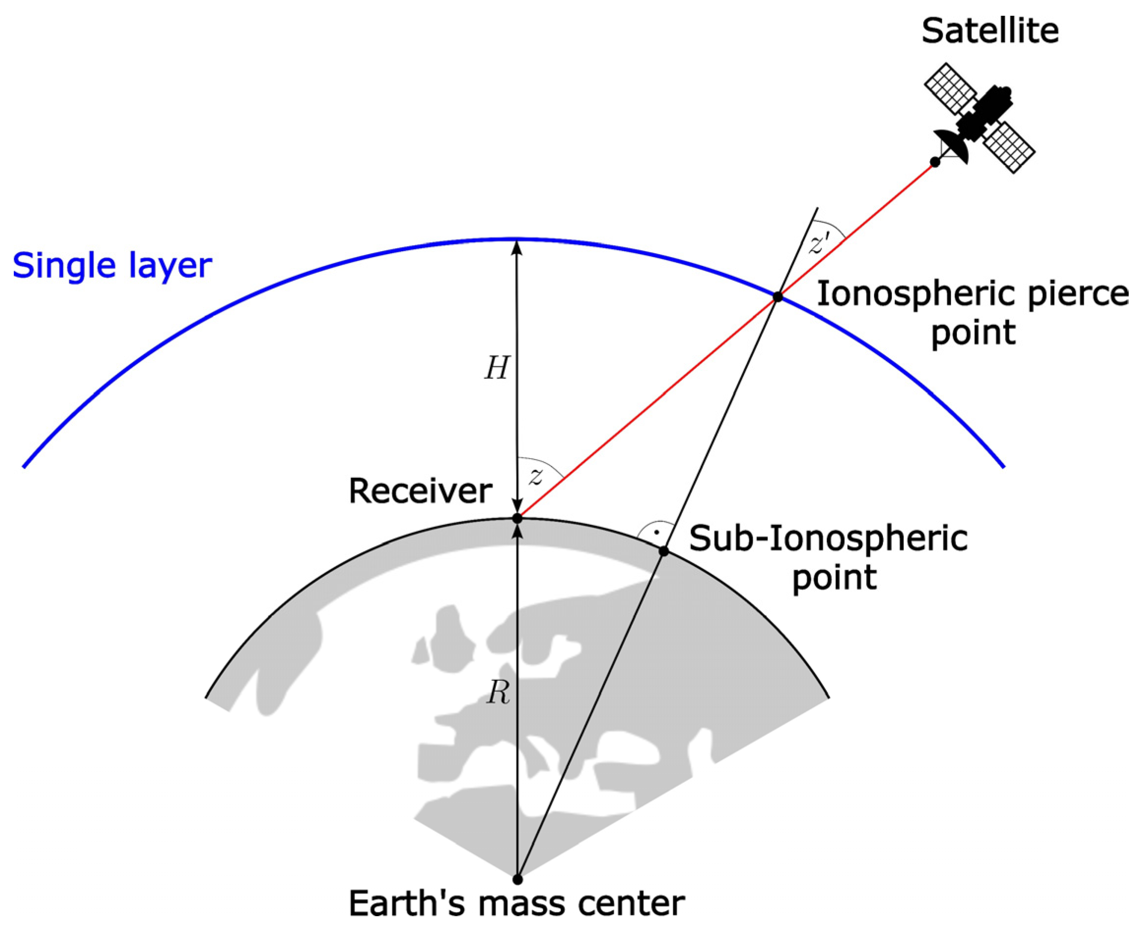
2.1.2. Mapping Function

It is important to note that ionospheric models that represent the deterministic component are based on the single-layer model (SLM), with an adequate mapping function. The SLM implies an approximation of the ionospheric layer in the following way:
  • It is assumed that the free electrons in the ionosphere are concentrated within a thin membrane (shell) at a constant height above the Earth’s surface;
  • The height of the ionospheric shell is adopted following the characteristic profile of the ionosphere;
  • The satellite signal emitted by the satellite changes its direction of propagation when interacting with the ionospheric shell;
  • The adopted height is considered a fixed value.
In addition, the mapping function is defined by the following equation:
F I z = T E C T E C V = 1 cos ( z ) = 1 1 sin 2 ( z ) ,
where z is defined as follows:
sin z = R R + H sin ( α z )
The defined mapping function is called the modified single-layer model (MSLM) mapping function where R is the mean Earth radius, H is the height of a single layer above Earth’s surface, α is an additional constant introduced in [6], and z and z are signal zenith distances at the height of the receiver (Earth’s surface) and at the height of a single layer. An interpretation of the SLM is shown in Figure 1.

2.1.3. Stochastic Component

The stochastic component of the ionosphere includes short-term and sudden variations of the ionosphere. Concerning previously defined modelling, using a geometry-free linear combination, the stochastic component of ionospheric models is treated as noise and cannot be modelled.
Therefore, to estimate the stochastic part, it is necessary to define a different functional model, within which it is possible to preserve information about short-term and sudden variations in the ionospheric layer. In this regard, instead of the geometry-free linear combination equations, it is necessary to use double-differences equations defined by Equation (4), where it is possible to define the double-differences ionospheric term Δ ρ i , j m , n I o n o directly as an unknown parameter.
Therefore, the parameters that define the stochastic component of the ionosphere are called stochastic ionospheric parameters (SIPs). In most cases, the number of SIPs is significant—it is necessary to estimate one parameter at a time within one observation epoch per satellite [6].

2.1.4. High-Order Terms and Signal-Bending Effect

The mathematical formulation of the ionospheric delay term Δ ρ I o n o can be obtained based on Fermat’s principle and the expression for the ionospheric refractive index. Taking into account the Appleton–Hartree equation [59,60,61] for the ionospheric refractive index, as well as the dispersive property of the ionosphere, where it is necessary to consider the phase and the group refractive index, the ionospheric delay term in the case of code pseudoranges is defined by the following equation [4]:
Δ ρ I o n o P = + k 1 + k 2 + k 3 + b ,
and in the case of phase pseudoranges:
Δ ρ I o n o L = k 1 1 2 k 2 1 3 k 3 + b .
In Equations (13) and (14), first-order term k 1 is defined by the well-known expression:
k 1 = 40.3 f 2 T E C
while k 2 and k 3 refer to the second-order and third-order terms, commonly known as the higher-order ionosphere (HOI) terms, and b stands for the ray path-bending correction.
During relatively quiet ionospheric conditions, the influence of the HOI terms can be considered negligible—even the second-order term can reach a value of about 2 mm. However, in periods with high ionospheric activity, the second-order term can reach a value of 1 cm, and even up to a few centimetres in extreme cases. The above has the consequence that the HOI terms are necessary to consider in the case of processing global and regional-scale GNSS networks, as well as in the case of precise point positioning (PPP).

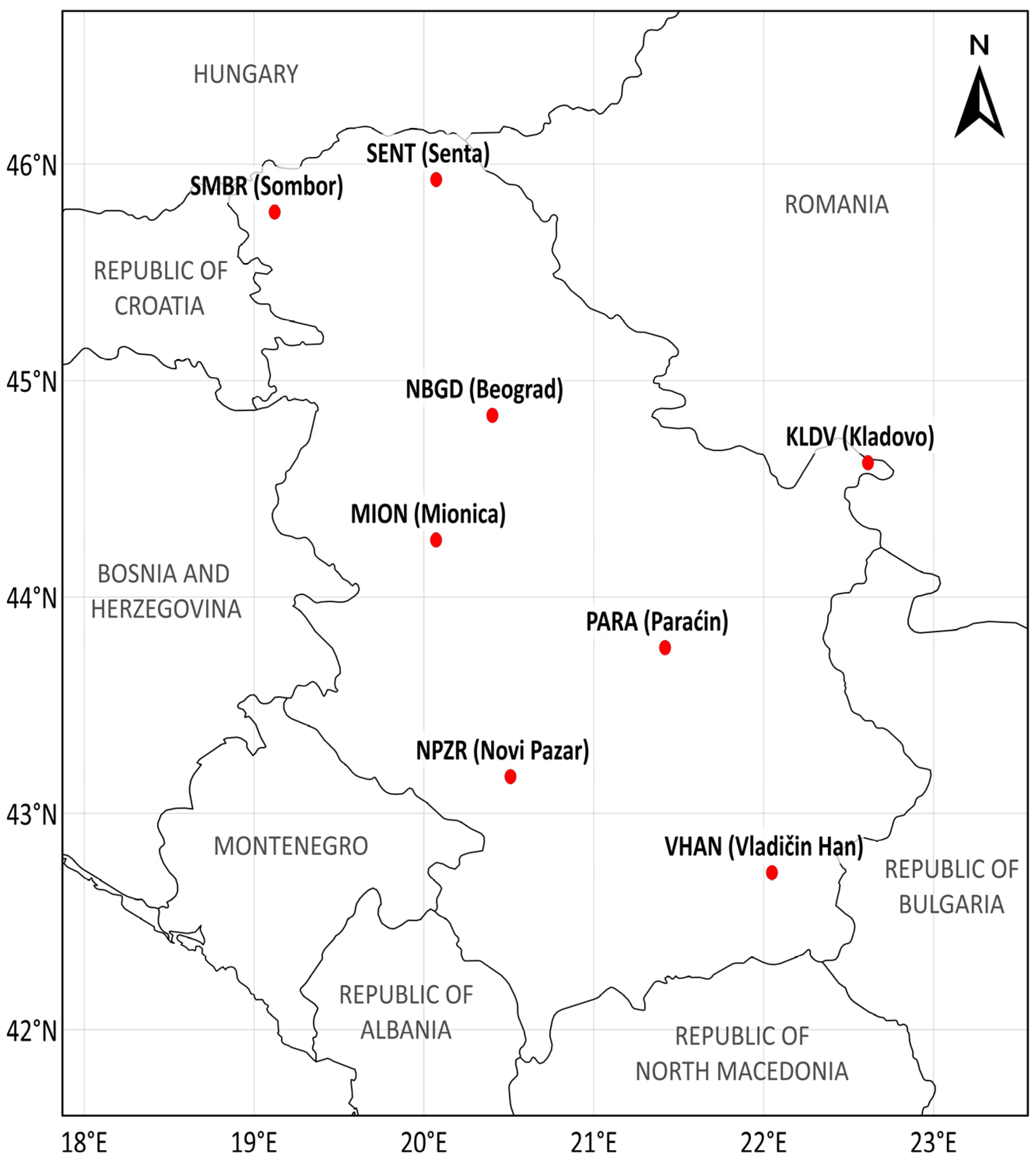
2.2. Study Area and Data Collection

Within the scope of this research, the study area covered the territory of the Republic of Serbia. To ensure reliable data processing, selecting an optimal number of continuously operational GNSS stations that would provide complete coverage of the area of interest was necessary. In addition, the position and stabilisation of the stations had to be such that unhindered reception of satellite signals was enabled, that there was no source of electromagnetic radiation in the vicinity of the stations, and that the stabilisation of the stations was performed adequately with an uninterrupted connection to external servers for adequate data archiving.
Considering all these factors, the best choice for the experimental dataset was the set of available permanent GNSS stations across Serbia. For this study, private company GentooARS kindly provided data from its GentooARS network (former GeotaurNet network) [62] in the RINEX (Receiver Independent Exchange) format. A total of seven stations were selected for further data processing, with their spatial distribution presented in Figure 2.
The selected GNSS stations were chosen to ensure uniform coverage of the area of interest while maintaining an optimal distance between them. The distance between neighbouring stations does not exceed approximately 150 km, ensuring adequate spatial distribution and reliable local ionospheric modelling. The general characteristics of the selected stations are presented in Table 1.
The experimental dataset covered the period of one GPS week, from 3 April 2022 to 9 April 2022 (GPS week 2204). When selecting the timeframe, special attention was given to ensuring that the solar and geomagnetic activity remained within moderate levels, avoiding extreme values associated with sudden, non-periodic events such as solar X-ray flares and geomagnetic storms. Figure 3 presents information on solar X-ray flares and the geomagnetic activity. Red bars indicate the daily number of solar X-ray flares (all classified as C-class), while blue bars represent K P index values. A K P index of 5 or greater indicates the occurrence of a geomagnetic storm [63]. Additionally, during the selected period, Dst index values ranged from −30 nT to +11 nT, confirming the absence of significant geomagnetic storms. The data can be accessed at https://wdc.kugi.kyoto-u.ac.jp/ (accessed on 10 April 2025).
The necessary information on the solar and geomagnetic activity, as well as the relevant indices (such as the number of solar X-ray flares, sunspot number, K P or A P index) can be found, for example, in [64,65].

2.3. Software and Computation Strategy

It is necessary to note that all data processing was performed within Bernese GNSS Software Version 5.4 and its defined sophisticated processing modules [30]. Additionally, the obtained results were calculated in the form of widely accepted data formats in the context of GNSS-derived ionospheric models such as the IONEX and ION spherical harmonic format [47,48], which ensure further use and implementation without additional conversion.
On the one hand, the computation strategy relies on a geometry-free linear combination of dual frequency data on the zero-differences level in the context of the deterministic component, with smoothed code observations. On the other hand, the stochastic component relies only on pure double-differences measurements [30]. The computation strategy consists of a relatively considerable number of software routines. These routines are directed toward solving various tasks, such as preparing the pole and orbit information, preprocessing, converting and synchronising observation data, synchronising the receiver clock, data filtering, noise reduction, etc.
All mandatory input data for the ionosphere determination can be downloaded from the CODE (Center for Orbit Determination in Europe) server [66], IGS [67], and CDDIS (Crustal Dynamics Data Information System) [68]. All model parameter values adopted in this research were selected based on the reference values established in the official literature [6,30]. This applies primarily to the choice of the coordinate system, the mapping function and its associated parameters within the single-layer ionospheric approximation, as well as the definition of the maximum degree and order used in the spherical harmonic expansion. This approach ensures methodological consistency and facilitates comparison with the existing global and regional models. Further information and details can be found in the official Bernese GNSS software user manual [30] and tutorial examples [69,70].
The entire research process can be structured into four main phases: (1) data collection and preprocessing, (2) determination of station-specific (local) ionospheric models, (3) determination of regional ionospheric models, and (4) validation. Figure 4 presents a schematic representation of the research process.

3. Results and Discussion

Based on the defined methodology and mathematical background, this section presents the key study results—station-specific (local) and regional ionospheric models, including all necessary details regarding preset parameters. Analysis of the results is presented in the form of statistical indicators, and an analysis of modelling parameters is also introduced. Additionally, the obtained results were validated to assess their accuracy and reliability.

3.1. Station-Specific (Local) Ionospheric Models

Station-specific ionospheric models based on the spherical harmonic expansion (addressed as local) were determined based on the following parameters:
  • Ionospheric modelling was performed by modelling the stochastic and deterministic components, considering higher-order ionospheric correction terms;
  • Unknown TEC parameters a n m and b n m of the spherical harmonic expansion were estimated for all GNSS stations with the initial values of the maximum degree and order m m a x = n m a x = 6 ;
  • The height of the ionosphere layer within the single-layer model was chosen as 450 km;
  • In terms of the mode of temporal modelling, the ionospheric models represented static (frozen) TEC structures in the sun-fixed frame with reference to specific time intervals;
  • This approach assumes that the TEC distribution remains approximately constant within each interval, allowing dynamic changes to be captured by generating successive models over time;
  • The MSLM mapping function was chosen for mapping slant TEC values into vertical TEC;
  • The solar magnetic (SM) coordinate system was chosen as the reference frame of coordinates ( β , s ) ;
  • Geomagnetic pole coordinates of the Earth-centred dipole axis were calculated for the epoch of interest based on the IGRF13 (international geomagnetic reference field) coefficients [71] and equations presented in [72];
  • Estimated spherical harmonic coefficients were developed in the ION format and valid for 24 h;
  • For each selected GNSS station, an estimate of unknown DCB parameters was also performed.
Estimated unknown SH coefficients were archived in the ION format. Based on the presented equations and methodology, local ionospheric models were determined for all the GNSS stations within the 1 min time interval. The created models are presented in Figure 5 for all the GNSS stations (the station’s ID mark is in the top-left corner of each graph) within GPS week 2204. Day marks are presented at the bottom of each graph in the form of the GPS week and DOW (day of week) mark, where zero (0) denotes Sunday, one (1) denotes Monday, and so on. It is important to note that discontinuities may appear at daily boundaries as a result of processing the data in separate 24 h clusters. These discontinuities are not indicative of real ionospheric variations but rather reflect limitations in the processing.
It can be noticed that the SM coordinate system was chosen as the reference frame. As the process of motion of charged particles is tightly linked to the geomagnetic field (a combination of rotation around a magnetic field line, bouncing along a field line), it is completely natural to present the ( β , s ) coordinates within the mentioned coordinate system in order to determine the TEC [6]. Furthermore, the SM coordinate system is in a certain way fixed on the Earth–Sun line, which results in a much slower variation of the ionosphere in time and a more accurate estimation of the parameters of the ionospheric models [33]. Definition and usage of the SM coordinate system, with other important systems as well, and all the necessary transformations are defined in several research studies, such as [72,73,74].
In addition to Figure 5, basic statistical data (minimum (MIN) and maximum (MAX) values and range (RANGE)) for all the GNSS stations within the research period is presented in Table 2. The last column presents the average MIN, MAX, and RANGE values for all the GNSS stations. It can be noted that day 2204 6 (9 April 2022) was the day with the greatest TEC values, and day 2204 1 (4 April 2022) was the day with the lowest TEC values.

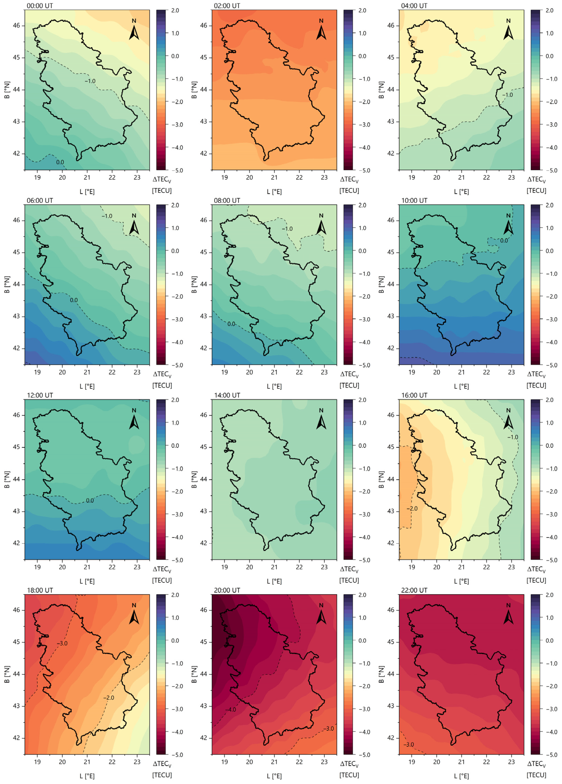
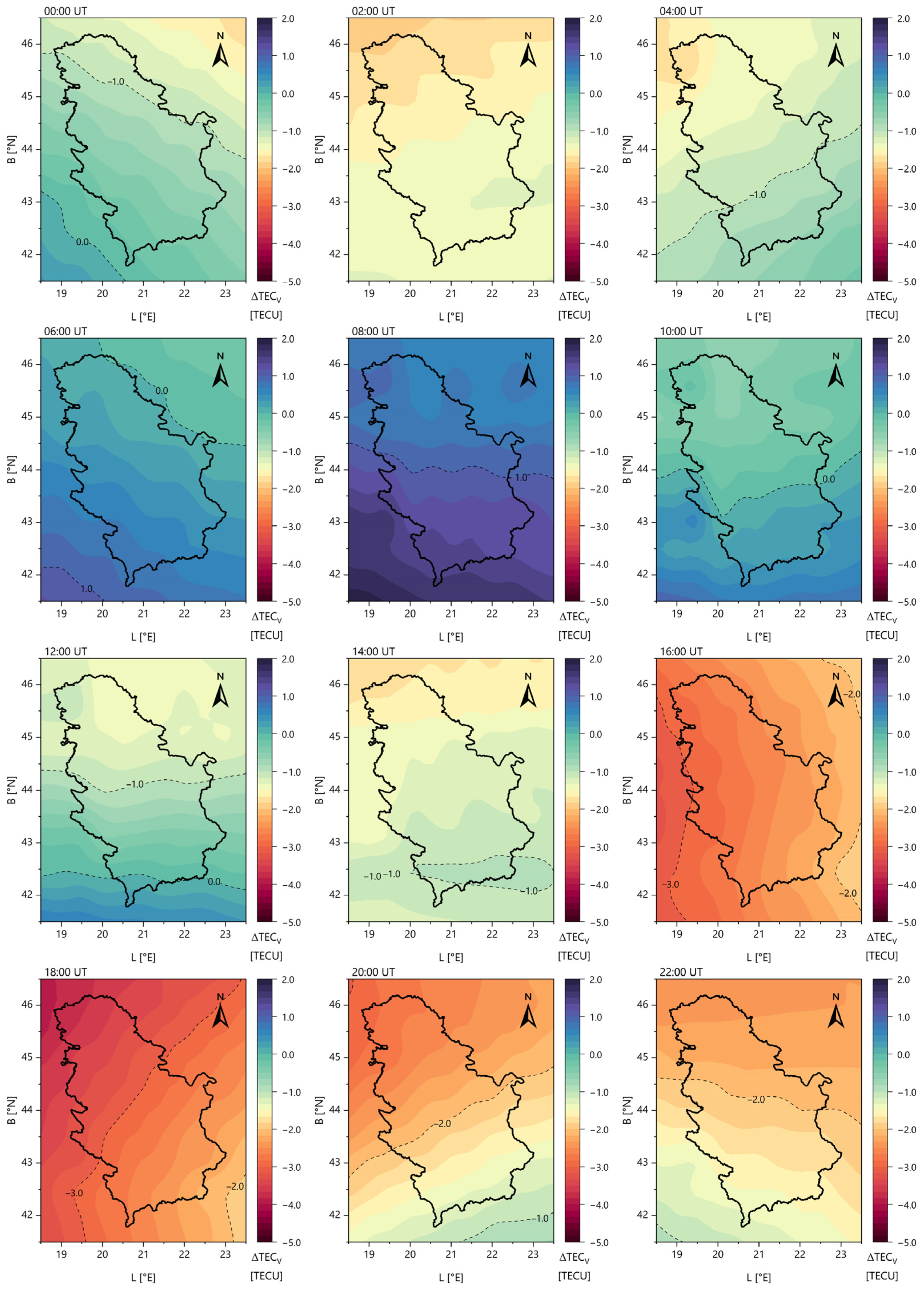
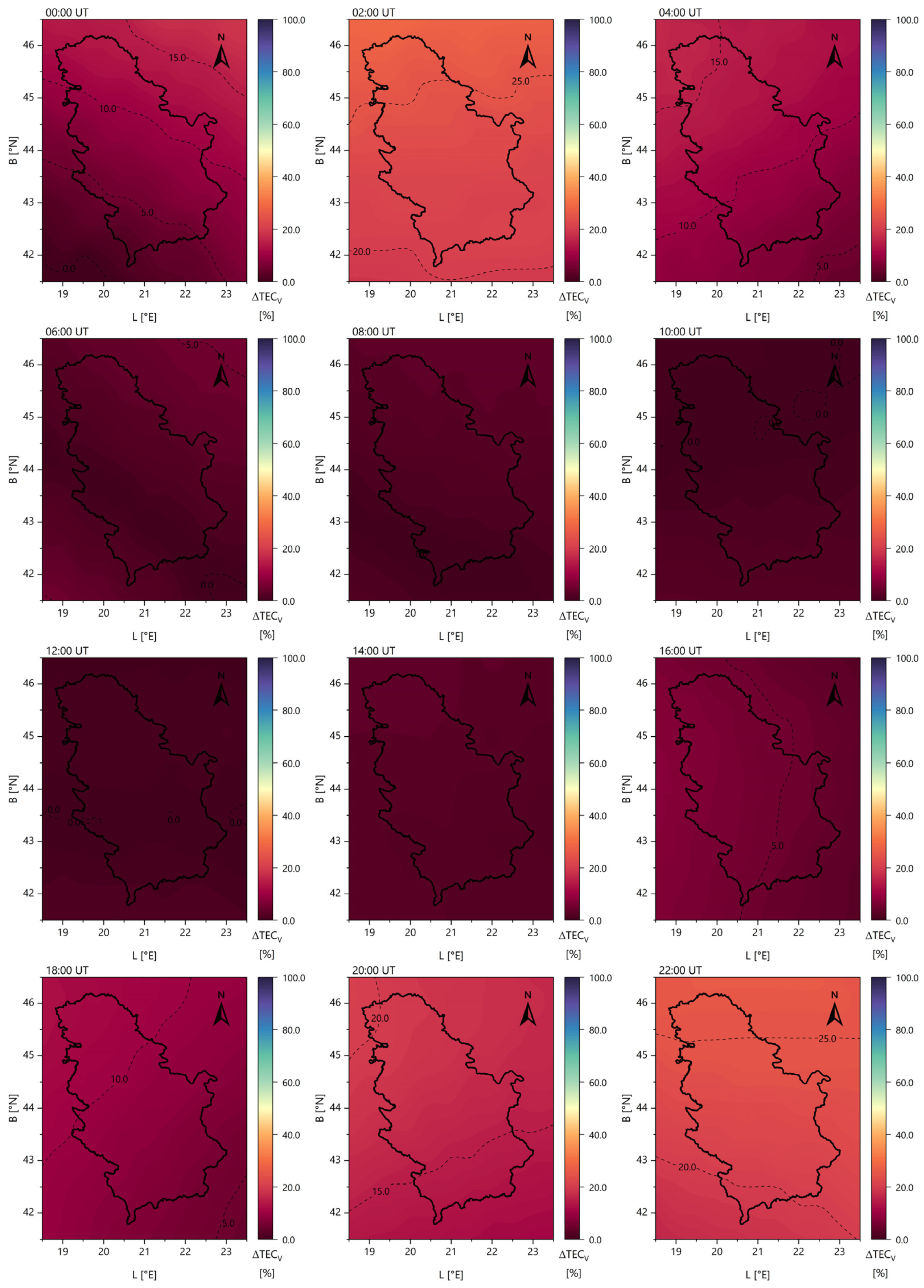
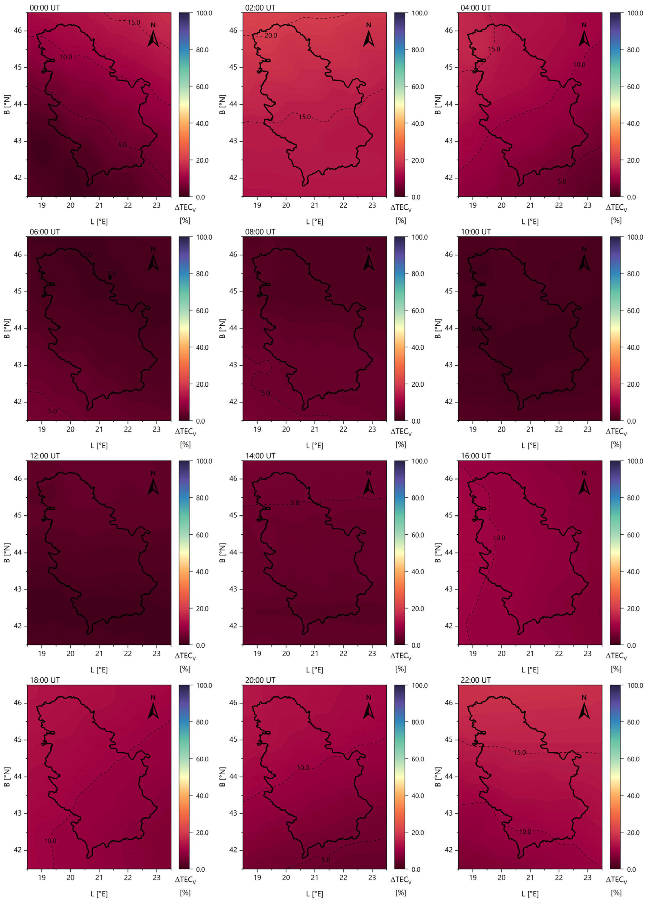
3.2. Regional Ionospheric Models

Regional ionospheric models (RIM) were determined based on the following parameters:
  • The modelling was conducted for the territory of the Republic of Serbia (one set of SH coefficients with the initial values m m a x = n m a x = 6 ), covering the latitude range from 42 N to 47 N and the longitude range from 18 E to 23 E;
  • The spatial resolution of the created models was 0.5 × 0.5 ( Δ B × Δ L );
  • The temporal resolution of the created regional models was 2 h.
The created models are presented in Figure 6 corresponding to the day with extreme TEC values within the research period—9 April 2022 (2204 6). The regional models were provided in both the ION and IONEX formats.
The quality analysis of the generated regional ionospheric models primarily focused on the TEC RMS (root mean square) parameter values, which serve as a formal measure of the accuracy of the ionospheric maps. Based on the numerical results, the following conclusions can be drawn:
  • The average RMS value was approximately 0.3 TECU, with most values ranging from 0.2 to 0.5 TECU. These values correspond to the ionospheric maps generated during the deterministic component modelling process.
  • The RMS values were nearly two to three times higher when modelling the stochastic component. The specific values depended on the TEC estimates obtained from stochastic modelling, with the RMS values increasing as the TEC values increased. In most cases, the RMS values ranged from 0.6 to 1.2 TECU.

3.3. Ionospheric Modelling Parameters Analysis

The estimation of unknown parameters in the spherical harmonic expansion of the total electron content is one of the most computationally demanding processes in terms of processing time. The total number of unknown parameters (coefficients) in the SH expansion is determined by the chosen maximum SH order and degree and can be calculated using the expression N c o e f . = n m a x + 1 2 in case of m m a x = n m a x .
Although the SH expansion is generally used for global modelling, in this study, it was applied over a limited geographic area. To ensure stability and meaningful parameter estimation, the maximum degree and order were carefully limited and evaluated. For this purpose, a partial dataset was selected to examine the mentioned influence. A total of ten solutions were analysed, each identified by an ID from one to ten, corresponding to the maximum degree and order of the SH expansion, as well as the total number of unknown coefficients ( N c o e f . ). The calculated TEC values were compared to assess the defined influence. Table 3 presents the differences for all the solutions relative to the sixth solution ( m m a x = n m a x = 8 ). For these differences, basic statistical parameters were computed: MIN, MAX, RANGE, average (AVG), and standard deviation (STDEV).
Based on the presented numerical data, i.e., the statistical parameters of the computed differences, it can be observed that when selecting the maximum degree and order of the SH expansion greater than eight, TEC values do not change significantly.

3.4. Validation

The obtained results were validated at the level of the created regional ionospheric models. Additionally, validation was performed for 9 April 2022 (2204 6) as the day with the maximum TEC values within the scope of the research. For this purpose, publicly available GIMs were used. Specifically, global ionospheric maps provided by the CODE Analysis Center and the IGS were selected for comparison. Figure 7 and Figure 8 illustrate the differences between the computed TEC values and those obtained from global ionospheric maps. Figure 7 presents the validation using data from the CODE Analysis Center, while Figure 8 shows the validation against IGS maps. These comparisons provide insight into the accuracy of the computed regional ionospheric models.
Additionally, Table 4 contains the numerical results of the described validation procedure. For each individual TEC map, the differences T E C V T E C V G I M were calculated, where T E C V stands for the calculated TEC values within the scope of the research, and T E C V G I M is the determined value from the global ionospheric maps (either from the CODE or the IGS). Basic statistical indicators were determined for the calculated differences, i.e., the minimum value, the maximum value, and the range. It is important to note that the spatial resolution of the GIM products differed from the resolution of the determined regional models. While the regional models were determined with a 0.5 × 0.5 resolution, GIM solutions are usually published with a resolution of 2.5 × 5.0 . This problem can be overcome using one of the interpolation models, such as basic linear interpolation. The temporal resolution did not differ—2 h for the created regional models and the GIM products.
By analysing the numerical results, it can be concluded that the obtained TEC values agreed with the values obtained based on global models up to the order of 5 TECU in an absolute sense (the minimum value of the difference was equal to −5.0 TECU, while the maximum value was 1.8 TECU). Regarding the comparison of individual maps during one day, the maximum range of differences amounted to 2.3 TECU.
To better interpret the presented differences, it was important to evaluate them in relation to the corresponding TEC magnitudes observed during the analysed period. Since TEC values can vary significantly throughout the day, expressing Δ T E C in percentage terms provides a more balanced and meaningful representation of the relative error. This type of analysis highlights whether the observed differences are truly significant or simply a reflection of natural TEC variability. Figure 9 and Figure 10 present percentage-based Δ T E C maps corresponding to the CODE and IGS models, respectively. The computed values are expressed in percentages and visualised directly on the maps for easier interpretation.
To evaluate the performance of the regional ionospheric models in relation to the CODE global models, percentage-based Δ T E C values were calculated by normalising the absolute differences with respect to the TEC values from the CODE maps ( T E C V C O D E ). This approach enabled a meaningful assessment of relative deviations, particularly across different times of day when TEC levels vary significantly.
The results show that percentage differences were generally highest during early morning and late evening hours. The maximum values ranged from 1.1% to 44.1%, with the peak deviations occurring at 2 UT (30.6%), 22 UT (26.2%), and 20 UT (21.3%). These time intervals correspond to periods of lower absolute TEC values, which amplifies the relative differences. On the other hand, the smallest differences were observed between 8 UT and 14 UT, where both minimum and maximum percentages dropped below 4%, and the minimum values dropped as low as 0%, indicating a strong agreement between the regional and global models during daytime hours.
In the comparison with the IGS global ionospheric models, the percentage-based Δ T E C values were again calculated relative to T E C V I G S . Similarly to above, the highest percentage differences occurred during the early hours of the day, with 23.8% at 2 UT and 18.8% at 22 UT. Other peaks were observed at 4 UT (17.7%) and 20 UT (14.4%). In contrast, from 6 UT to 14 UT, the maximum percentage differences remained below 6.5%, and the minimum values approached 0%, indicating a strong consistency between the models during the midday period.
Such behaviour was expected, given that global models tend to underrepresent localised ionospheric dynamics during transition periods (sunrise/sunset), while regional models, tailored to the Serbian GNSS network, are more responsive to local variations.
Finally, it is important to mention that the global models used in the external validation procedure were created based on GNSS observations from GNSS networks, from which no data were related to the relevant territory of the Republic of Serbia.

4. Conclusions

This study explored the potential of GNSS-based ionospheric modelling by developing local and regional models using the SH expansion. The ionospheric parameters were modelled by analysing the overall ionospheric influence, decomposed into the deterministic and stochastic components while considering higher-order correction terms and signal-bending effects. Local ionospheric models were generated for all the GNSS stations in the ION spherical harmonic format, enabling further calculations of the TEC values at any epoch. Meanwhile, regional models were produced in the ION and IONEX formats, represented as ionospheric maps with a spatial resolution of 0.5 × 0.5 and a temporal resolution of 2 h. These formats, widely recognised as standard for GNSS data processing, ensure the practical applicability of the models, instilling confidence in their potential use.
The results demonstrate that the proposed methodology provides highly accurate TEC estimates, with an average RMS error of 0.3 TECU, confirming its suitability for regional and local ionospheric studies and reassuring the audience about the reliability of the methodology.
The following conclusions can be drawn from the results:
  • Modelling the TEC as a harmonic function, i.e., by estimating the SH expansion coefficients, results in local ionospheric models that represent ionospheric conditions more accurately than traditional Taylor series-based approaches.
  • High-resolution regional ionospheric models can be developed based on local models, offering a more accurate representation of the ionosphere compared to publicly available GIMs.
  • The developed local and regional models incorporate both the deterministic and stochastic components, providing a detailed and precise depiction of ionospheric conditions over the study area within the defined timeframe.
  • The agreement between the generated ionospheric models and GIM data was observed within 5 TECU, indicating a significant improvement in regional representation for GNSS data processing.
  • The choice of the maximum degree and order in the SH expansion plays a crucial role in the accuracy of the models and should not be overlooked when selecting modelling parameters. It was shown that TEC values do not change significantly with an increase in the maximum degree and order of the SH expansion above eight.
  • TEC RMS values primarily depend on the type of the modelled ionospheric component, particularly on the presence of stochastic parameters. While the RMS values ranged from 0.2 to 0.5 TECU for the deterministic components, introducing the stochastic components can increase RMS values by two to three times. It is worth noting that RMS values associated with global ionospheric maps typically span a broader range, with extreme cases reaching values as high as 2 TECU.
Moreover, the local SH-based approach enables a more detailed and adaptable representation of the ionosphere over small geographic regions, particularly where global models lack resolution or observational coverage. Beyond validation, such models offer practical advantages in GNSS data processing, especially for resolving carrier phase ambiguities and enhancing single-frequency positioning performance in smaller areas. This further supports the operational relevance of developing high-resolution national models, particularly in regions not well-represented in global ionospheric networks.
While this study has made significant strides in GNSS-based ionospheric modelling, there are still several avenues for future research. Further investigation is encouraged in several directions, including the evaluation of modelling parameter selection (e.g., assessing the impact of varying key parameters on model performance), validation using independent data sources (e.g., ionosondes or COSMIC radio occultation), and the assessment of the stochastic component’s contribution to capturing sudden ionospheric variations. Additionally, expanding the methodology to develop larger regional models, such as a regional ionospheric model of the Balkan Peninsula, could further enhance our understanding of ionospheric conditions under both quiet and disturbed conditions.

Author Contributions

Conceptualisation, D.P., O.O. and A.N.; methodology, D.P. and O.O.; software, D.P. and O.O.; validation, D.P. and M.T.-D.; formal analysis, D.P. and S.G.; investigation, D.P.; resources, D.P. and O.O.; data curation, D.P.; writing—original draft preparation, D.P.; writing—review and editing, O.O., A.N., A.K., M.T.-D., S.G. and S.K.; visualisation, D.P. and S.K.; supervision, D.P., O.O. and A.N. All authors have read and agreed to the published version of the manuscript.

Funding

This research was funded by the Ministry of Education, Science, and Technological Development, Republic of Serbia, grant No. 451-03-68/2020-14/200092 (University of Belgrade, Faculty of Civil Engineering).

Institutional Review Board Statement

Not applicable.

Informed Consent Statement

Not applicable.

Data Availability Statement

The raw GNSS observation data used in this study are proprietary and belong to private company GentooARS. Access to these data is restricted. The results of this research, including the generated ionospheric models, are available within this article. Additionally, datasets in the ION and IONEX formats can be provided upon request to the corresponding author. The auxiliary datasets required for preprocessing within Bernese GNSS software are publicly available through the following sources: CODE [66], IGS [67], and CDDIS [68,75].

Acknowledgments

The authors would like to express their gratitude to GentooARS for providing GNSS observation data from the GentooARS network.

Conflicts of Interest

The authors declare no conflicts of interest.

Abbreviations

The following abbreviations are used in this manuscript (in the alphabetic order):
CODECenter for Orbit Determination in Europe
COSPARCommittee on Space Research
DCBDifferential code bias
DGRDi Giovanni and Radicella
DOWDay of week
ESAEuropean Space Agency
GIMGlobal ionospheric maps
GLONASSGlobalnaya Navigationnaya Sputnikovaya Sistema
GNSSGlobal navigation satellite system
GPSGlobal Positioning System
HOIHigher-order ionosphere
ICTPAbdus Salam International Centre for Theoretical Physics
IGAMInstitute for Geophysics, Astrophysics, and Meteorology
IGSInternational GNSS Service
IONEXIONosphere map EXchange
IRIInternational Reference Ionosphere
ITUInternational Telecommunication Union
LFLow-frequency
MSLMModified single-layer model
PPPPrecise point positioning
RIMRegional ionospheric models
RMSRoot mean square
SIPStochastic ionospheric parameter
SLMSingle-layer model
SMSolar magnetic
TIDTravelling ionospheric disturbance
URSIInternational Union of Radio Science
VLFVery-low-frequency
RTKReal-time kinematic
CDDISCrustal Dynamics Data Information System
RINEXReceiver Independent Exchange
SHSpherical harmonic
IGRFInternational geomagnetic reference field
TECTotal electron content
TECUTotal electron content unit
TECVVertical total electron content

References

  1. Davies, K. Ionospheric Radio, 3rd ed.; The Institution of Engineering and Technology: London, UK, 1990. [Google Scholar] [CrossRef]
  2. Schunk, R.; Nagy, A. Ionospheres. Physics, Plasma Physics, and Chemistry, 2nd ed.; Cambridge University Press: New York, NY, USA, 2009. [Google Scholar] [CrossRef]
  3. Budden, K.B. The Propagation of Radio Waves. The Theory of Radio Waves of Low Power in the Ionosphere and Magnetosphere, 1st ed.; Cambridge University Press: New York, NY, USA, 1985. [Google Scholar] [CrossRef]
  4. Memarzadeh, Y. Ionospheric Modelling for Precise GNSS Applications. Ph.D. Thesis, Delft University of Technology, Delft, The Netherlands, 2009. [Google Scholar]
  5. Nina, A.; Nico, G.; Odalović, O.; Čadež, V.M.; Todorović Drakul, M.; Radovanović, M.; Popović, L.Č. GNSS and SAR Signal Delay in Perturbed Ionospheric D-Region During Solar X-Ray Flares. IEEE Geosci. Remote Sens. Lett. 2020, 17, 1198–1202. [Google Scholar] [CrossRef]
  6. Schaer, S. Mapping and Predicting the Earth’s Ionosphere Using the Global Positioning System. Ph.D. Thesis, Astronomical Institute, University of Bern, Bern, Switzerland, 1999. [Google Scholar]
  7. Hofmann-Wellenhof, B.; Lichtenegger, H.; Wasle, E. GNSS—Global Navigation Satellite Systems. GPS, GLONASS, Galileo, and More, 1st ed.; SpringerWienNewYork: Vienna, Austria, 2008. [Google Scholar] [CrossRef]
  8. Seeber, G. Satellite Geodesy. Foundations, Methods, and Applications, 2nd ed.; De Gruyter: Berlin, Germany, 2003. [Google Scholar] [CrossRef]
  9. Bilitza, D. IRI the International Standard for the Ionosphere. Adv. Radio Sci. 2018, 16, 1–11. [Google Scholar] [CrossRef]
  10. Radicella, S.M.; Nava, B. Chapter 6—Empirical ionospheric models. In The Dynamical Ionosphere. A Systems Approach to Ionospheric Irregularity, 1st ed.; Materassi, M., Forte, B., Coster, A.J., Skone, S., Eds.; Elsevier: Amsterdam, The Netherlands, 2020; pp. 39–53. [Google Scholar] [CrossRef]
  11. Bilitza, D. International Reference Ionosphere 2000. Radio Sci. 2001, 36, 261–275. [Google Scholar] [CrossRef]
  12. Bilitza, D.; Altadill, D.; Zhang, Y.; Mertens, C.; Truhlik, V.; Richards, P.; McKinnell, L.-A.; Reinisch, B. The International Reference Ionosphere 2012—A model of international collaboration. J. Space Weather Space Clim. 2014, 4, A07. [Google Scholar] [CrossRef]
  13. Bilitza, D.; Altadill, D.; Truhlik, V.; Shubin, V.; Galkin, I.; Reinisch, B.; Huang, X. International Reference Ionosphere 2016: From ionospheric climate to real-time weather predictions. Space Weather 2017, 15, 418–429. [Google Scholar] [CrossRef]
  14. Bilitza, D.; Pezzopane, M.; Truhlik, V.; Altadill, D.; Reinisch, B.W.; Pignalberi, A. The International Reference Ionosphere model: A review and description of an ionospheric benchmark. Rev. Geophys. 2022, 60, e2022RG000792. [Google Scholar] [CrossRef]
  15. Di Giovanni, G.; Radicella, S.M. An analytical model of the electron density profile in the ionosphere. Adv. Space Res. 1990, 10, 27–30. [Google Scholar] [CrossRef]
  16. Nava, B.; Coïsson, P.; Radicella, S.M. A new version of the NeQuick ionosphere electron density model. J. Atmos. Sol.-Terr. Phys. 2008, 70, 1856–1862. [Google Scholar] [CrossRef]
  17. Nava, B.; Radicella, S.M.; Azpilicueta, F. Data ingestion into NeQuick 2. Radio Sci. 2011, 46, RS0D17. [Google Scholar] [CrossRef]
  18. Radicella, S.M. The NeQuick model genesis, uses and evolution. Ann. Geophys. 2009, 52, 417–422. [Google Scholar] [CrossRef]
  19. Subirana, J.S.; Zornoza, J.M.J.; Hernández-Pajares, M. GNSS Data Processing. Volume I: Fundamentals and Algorithms, 1st ed.; TM-23/1; ESA Communications: Noordwijk, The Netherlands, 2013. [Google Scholar]
  20. Falcone, M.; Hahn, J.; Burger, T. Galileo. In Springer Handbook of Global Navigation Satellite Systems, 1st ed.; Teunissen, P.J.G., Montenbruck, O., Eds.; Springer International Publishing: Cham, Switzerland, 2017; pp. 247–272. [Google Scholar] [CrossRef]
  21. Semeter, J. Chapter 15—High-resolution approaches to Ionospheric exploration. In The Dynamical Ionosphere. A Systems Approach to Ionospheric Irregularity, 1st ed.; Materassi, M., Forte, B., Coster, A.J., Skone, S., Eds.; Elsevier: Amsterdam, The Netherlands, 2020; pp. 223–241. [Google Scholar] [CrossRef]
  22. Bibl, K.; Reinisch, B.W. The universal digital ionosonde. Radio Sci. 1978, 13, 519–530. [Google Scholar] [CrossRef]
  23. Reinisch, B.W.; Galkin, I.A.; Khmyrov, G.M.; Kozlov, A.V.; Bibl, K.; Lisysyan, I.A.; Cheney, G.P.; Huang, X.; Kitrosser, D.F.; Paznukhov, V.V.; et al. New Digisonde for research and monitoring applications. Radio Sci. 2009, 44, RS0A24. [Google Scholar] [CrossRef]
  24. Mošna, Z.; Kouba, D.; Knížová, P.K.; Burešová, D.; Chum, J.; Šindelářová, T.; Urbář, J.; Boška, J.; Saxonbergová-Jankovičová, D. Ionospheric storm of September 2017 observed at ionospheric station Pruhonice, the Czech Republic. Adv. Space Res. 2020, 65, 115–128. [Google Scholar] [CrossRef]
  25. Wang, J.; Chen, G.; Yu, T.; Deng, Z.; Yan, X.; Yang, N. Middle-Scale Ionospheric Disturbances Observed by the Oblique-Incidence Ionosonde Detection Network in North China after the 2011 Tohoku Tsunamigenic Earthquake. Sensors 2021, 21, 1000. [Google Scholar] [CrossRef]
  26. Nina, A.; Nico, G.; Mitrović, S.T.; Čadež, V.M.; Milošević, I.R.; Radovanović, M.; Popović, L.Č. Quiet Ionospheric D-Region (QIonDR) Model Based on VLF/LF Observations. Remote Sens. 2021, 13, 483. [Google Scholar] [CrossRef]
  27. Nina, A. Modelling of the Electron Density and Total Electron Content in the Quiet and Solar X-ray Flare Perturbed Ionospheric D-Region Based on Remote Sensing by VLF/LF Signals. Remote Sens. 2022, 14, 54. [Google Scholar] [CrossRef]
  28. Pal, S.; Hobara, Y.; Shvets, A.; Schnoor, P.W.; Hayakawa, M.; Koloskov, O. First Detection of Global Ionospheric Disturbances Associated with the Most Powerful Gamma Ray Burst GRB221009A. Atmosphere 2023, 14, 217. [Google Scholar] [CrossRef]
  29. Langley, R.B.; Teunissen, P.J.; Montenbruck, O. Introduction to GNSS. In Springer Handbook of Global Navigation Satellite Systems, 1st ed.; Teunissen, P.J.G., Montenbruck, O., Eds.; Springer International Publishing: Cham, Switzerland, 2017; pp. 3–23. [Google Scholar] [CrossRef]
  30. Dach, R.; Lutz, S.; Walser, P.; Fridez, P. Bernese GNSS Software, Version 5.2; User Manual; University of Bern, Bern Open Publishing: Bern, Switzerland, 2015. [CrossRef]
  31. Klobuchar, J.A. Ionospheric Time-Delay Algorithm for Single-Frequency GPS Users. IEEE Trans. Aerosp. Electron. Syst. 1987, AES-23, 325–331. [Google Scholar] [CrossRef]
  32. Wild, U. Ionosphere and Geodetic Satellite Systems: Permanent GPS Tracking Data for Modelling and Monitoring. Ph.D. Thesis, Swiss Geodetic Commission, ETH Zurich, Zurich, Switzerland, 1994. [Google Scholar]
  33. Komjathy, A. Global Ionospheric Total Electron Content Mapping Using the Global Positioning System. Ph.D. Thesis, Department of Geodesy and Geomatics Engineering Technical Report No. 188, University of New Brunswick, Fredericton, NB, Canada, 1997. [Google Scholar]
  34. Schaer, S.; Beutler, G.; Mervart, L.; Rothacher, M.; Wild, U. Global and regional ionosphere models using the GPS double difference phase observable. In Proceedings of the IGS Workshop, Potsdam, Germany, 15–17 May 1995. [Google Scholar]
  35. Schaer, S.; Beutler, G.; Rothacher, M. Mapping and predicting the ionosphere. In Proceedings of the IGS AC Workshop, Darmstadt, Germany, 9–11 February 1998. [Google Scholar]
  36. Hernández-Pajares, M.; Juan, J.M.; Sanz, J.; Orus, R.; Garcia-Rigo, A.; Feltens, J.; Komjathy, A.; Schaer, S.C.; Krankowski, A. The IGS VTEC maps: A reliable source of ionospheric information since 1998. J. Geod. 2009, 83, 263–275. [Google Scholar] [CrossRef]
  37. International GNSS Service. Available online: https://igs.org/ (accessed on 17 March 2025).
  38. Hernández-Pajares, M.; Roma-Dollase, D.; Krankowski, A.; García-Rigo, A.; Orús-Pérez, R. Methodology and consistency of slant and vertical assessments for ionospheric electron content models. J. Geod. 2017, 91, 1405–1414. [Google Scholar] [CrossRef]
  39. Roma-Dollase, D.; Hernández-Pajares, M.; Krankowski, A.; Kotulak, K.; Ghoddousi-Fard, R.; Yuan, Y.; Li, Z.; Zhang, H.; Shi, C.; Wang, C.; et al. Consistency of seven different GNSS global ionospheric mapping techniques during one solar cycle. J. Geod. 2017, 92, 691–706. [Google Scholar] [CrossRef]
  40. Li, Z.; Wang, N.; Hernández-Pajares, M.; Yuan, Y.; Krankowski, A.; Liu, A.; Zha, J.; García-Rigo, A.; Roma-Dollase, D.; Yang, H.; et al. IGS real-time service for global ionospheric total electron content modelling. J. Geod. 2020, 94, 32. [Google Scholar] [CrossRef]
  41. Cherniak, I.; Krankowski, A.; Zakharenkova, I. Observation of the ionospheric irregularities over the Northern Hemisphere: Methodology and service. Radio Sci. 2014, 49, 653–662. [Google Scholar] [CrossRef]
  42. Galkin, I.; Froń, A.; Reinisch, B.; Hernández-Pajares, M.; Krankowski, A.; Nava, B.; Bilitza, D.; Kotulak, K.; Flisek, P.; Li, Z.; et al. Global Monitoring of Ionospheric Weather by GIRO and GNSS Data Fusion. Atmosphere 2022, 13, 371. [Google Scholar] [CrossRef]
  43. Todorović Drakul, M. Ionosphere Modelling for the Purposes of Determination of Influence to the GPS Signals Within Network RTK Environment. Ph.D. Thesis, University of Belgrade, Faculty of Civil Engineering, Belgrade, Serbia, 2016. [Google Scholar]
  44. Todorović Drakul, M.; Čadez, V.; Bajčetić, J.; Popović, L.; Blagojević, D.; Nina, A. Behaviour of electron content in the ionospheric D-region during solar X-ray flares. Serbian Astron. J. 2016, 193, 11–18. [Google Scholar] [CrossRef]
  45. Todorović Drakul, M.; Samardžić-Petrović, M.; Grekulović, S.; Odalović, O.; Blagojević, D. Modelling extreme values of the total electron content: Case study of Serbia. Geofizika 2017, 34, 297–314. [Google Scholar] [CrossRef]
  46. Natras, R.; Goss, A.; Halilovic, D.; Magnet, N.; Mulic, M.; Schmidt, M.; Weber, R. Regional Ionosphere Delay Models Based on CORS Data and Machine Learning. Navig. J. Inst. Navig. 2023, 70, navi.577. [Google Scholar] [CrossRef]
  47. Schaer, S.; Gurtner, W.; Feltens, J. IONEX: The IONosphere Map Exchange Format Version 1.0. In Proceedings of the IGS AC Workshop, Darmstadt, Germany, 9–11 February 1998. [Google Scholar]
  48. Schaer, S.; Gurtner, W.; Feltens, J. IONEX: The IONosphere Map Exchange Format Version 1.1. In Proceedings of the IGS AC Workshop, Darmstadt, Germany, 9–11 February 1998. [Google Scholar]
  49. Padokhin, A.M.; Andreeva, E.S.; Nazarenko, M.O.; Kalashnikova, S.A. Phase-Difference Approach for GNSS Global Ionospheric Total Electron Content Mapping. Radiophys. Quantum Electron. 2022, 65, 481–495. [Google Scholar] [CrossRef]
  50. Ren, X.; Zhang, X.; Xie, W.; Zhang, K.; Yuan, Y.; Li, X. Global Ionospheric Modelling Using Multi-GNSS: BeiDou, Galileo, and GPS. Sci. Rep. 2016, 6, 33499. [Google Scholar] [CrossRef]
  51. Zhang, Q.; Zhao, Q. Analysis of the Data Processing Strategies of Spherical Harmonic Expansion Model on Global Ionosphere Mapping for Moderate Solar Activity. Adv. Space Res. 2019, 63, 1214–1226. [Google Scholar] [CrossRef]
  52. Choi, B.-K.; Lee, W.K.; Cho, S.-K.; Park, J.-U.; Park, P.-H. Global GPS Ionospheric Modelling Using Spherical Harmonic Expansion Approach. J. Astron. Space Sci. 2010, 27, 359–366. [Google Scholar] [CrossRef]
  53. Mehmood, M.; Shahid, I.; Nawaz, R.; Mushtaq, S. Total Electron Content (TEC) Estimation over Pakistan from Local GPS Network. Ann. Geophys. 2021, 64, GD102. [Google Scholar] [CrossRef]
  54. Liu, J.; Chen, R.; An, J.; Hyyppa, J. Spherical Cap Harmonic Analysis of the Arctic Ionospheric TEC for One Solar Cycle. J. Geophys. Res. Space Phys. 2014, 119, 601–619. [Google Scholar] [CrossRef]
  55. Li, W.; Zhao, D.; Shen, Y.; Zhang, K. Modeling Australian TEC Maps Using Long-Term Observations of Australian Regional GPS Network by Artificial Neural Network-Aided Spherical Cap Harmonic Analysis Approach. Remote Sens. 2020, 12, 3851. [Google Scholar] [CrossRef]
  56. Liu, J.; Chen, R.; Wang, Z.; Zhang, H. Spherical Cap Harmonic Model for Mapping and Predicting Regional TEC. GPS Solut. 2011, 15, 109–119. [Google Scholar] [CrossRef]
  57. Hauschild, A. Basic Observation Equations. In Springer Handbook of Global Navigation Satellite Systems, 1st ed.; Teunissen, P.J.G., Montenbruck, O., Eds.; Springer International Publishing: Cham, Switzerland, 2017; pp. 561–582. [Google Scholar] [CrossRef]
  58. Jakowski, N. Ionosphere Monitoring. In Springer Handbook of Global Navigation Satellite Systems, 1st ed.; Teunissen, P.J.G., Montenbruck, O., Eds.; Springer International Publishing: Cham, Switzerland, 2017; pp. 1139–1162. [Google Scholar] [CrossRef]
  59. Hobiger, T.; Jakowski, N. Atmospheric Signal Propagation. In Springer Handbook of Global Navigation Satellite Systems, 1st ed.; Teunissen, P.J.G., Montenbruck, O., Eds.; Springer International Publishing: Cham, Switzerland, 2017; pp. 165–193. [Google Scholar] [CrossRef]
  60. Seemala, G.K. Chapter 4—Estimation of ionospheric total electron content (TEC) from GNSS observations. In Atmospheric Remote Sensing: Principles and Applications, 1st ed.; Singh, A.K., Tiwari, S., Eds.; Elsevier: Amsterdam, The Netherlands, 2023; pp. 63–84. [Google Scholar] [CrossRef]
  61. Böhm, J.; Schuh, H. Atmospheric Effects in Space Geodesy, 1st ed.; Springer: Berlin/Heidelberg, Germany, 2013. [Google Scholar] [CrossRef]
  62. Odalović, O.; Petković, D.; Grekulović, S.; Todorović Drakul, M. A compliance assessment of GNSS station networks in Serbia. J. Geogr. Inst. Jovan Cvijić SASA 2024, 74, 47–61. [Google Scholar] [CrossRef]
  63. Space Weather Prediction Center, National Oceanic and Atmospheric Administration. Available online: https://www.swpc.noaa.gov/noaa-scales-explanation (accessed on 11 January 2024).
  64. Space Weather. Available online: https://www.spaceweatherlive.com/en/archive.html (accessed on 4 August 2023).
  65. The Helmholtz Centre Potsdam—GFZ German Research Centre for Geosciences. Available online: https://kp.gfz-potsdam.de/en/ (accessed on 25 December 2023).
  66. Dach, R.; Schaer, S.; Arnold, D.; Brockmann, E.; Kalarus, M.S.; Lasser, M.; Stebler, P.; Jäggi, A. CODE Final Product Series for the IGS; Astronomical Institute, University of Bern: Bern, Switzerland, 2024; Available online: https://www.aiub.unibe.ch/download/CODE (accessed on 17 July 2023). [CrossRef]
  67. Johnston, G.; Riddell, A.; Hausler, G. The International GNSS Service. In Springer Handbook of Global Navigation Satellite Systems, 1st ed.; Teunissen, P.J.G., Montenbruck, O., Eds.; Springer International Publishing: Cham, Switzerland, 2017; pp. 967–982. [Google Scholar] [CrossRef]
  68. Noll, C. The Crustal Dynamics Data Information System: A resource to support scientific analysis using space geodesy. Adv. Space Res. 2010, 45, 1421–1440. [Google Scholar] [CrossRef]
  69. Dach, R.; Fridez, P. Bernese GNSS Software, Version 5.2; Tutorial; University of Bern, Bern Open Publishing: Bern, Switzerland, 2021.
  70. Dach, R.; Arnold, D. Bernese GNSS Software, Version 5.4; Tutorial; University of Bern, Bern Open Publishing: Bern, Switzerland, 2025.
  71. Alken, P.; Thébault, E.; Beggan, C.D.; Amit, H.; Aubert, J.; Baerenzung, J.; Bondar, T.N.; Brown, W.J.; Califf, S.; Chambodut, A.; et al. International Geomagnetic Reference Field: The thirteenth generation. Earth Planets Space 2021, 73, 49. [Google Scholar] [CrossRef]
  72. Laundal, K.M.; Richmond, A.D. Magnetic Coordinate Systems. Space Sci. Rev. 2017, 206, 27–59. [Google Scholar] [CrossRef]
  73. Hapgood, M.A. Space physics coordinate transformations: A user guide. Planet. Space Sci. 1992, 40, 711–717. [Google Scholar] [CrossRef]
  74. Russell, C.T. Geophysical Coordinate Transformations. Cosm. Electrodyn. 1971, 2, 184–196. [Google Scholar]
  75. Crustal Dynamics Data Information System (CDDIS DAAC). Available online: https://cddis.nasa.gov/archive/gnss/products/ionex/ (accessed on 17 July 2023).
Figure 1. Graphical interpretation of a single-layer model.
Atmosphere 16 00496 g001
Figure 2. Spatial distribution of the selected GNSS stations in the Republic of Serbia.
Atmosphere 16 00496 g002
Figure 3. The information on solar X-ray flares and the geomagnetic activity.
Atmosphere 16 00496 g003
Figure 4. Schematic representation of the research process.
Atmosphere 16 00496 g004
Figure 5. Local ionospheric models for GPS week 2204 for the chosen dataset (7 GNSS stations in the territory of the Republic of Serbia).
Atmosphere 16 00496 g005
Figure 6. Regional ionospheric model for the territory of the Republic of Serbia for 9 April 2022 (GPS week 2204, DOW 6).
Atmosphere 16 00496 g006
Figure 7. Validation of the regional ionospheric models with global ionospheric maps published by the CODE for 9 April 2022 (GPS week 2204, DOW 6).
Atmosphere 16 00496 g007
Figure 8. Validation of the regional ionospheric models with global ionospheric maps published by the IGS for 9 April 2022 (GPS week 2204, DOW 6).
Atmosphere 16 00496 g008
Figure 9. Percentage-based Δ T E C validation maps of the regional ionospheric models against the global ionospheric maps published by the CODE for 9 April 2022 (GPS week 2204, DOW 6).
Atmosphere 16 00496 g009
Figure 10. Percentage-based Δ T E C validation maps of the regional ionospheric models against the global ionospheric maps published by the IGS for 9 April 2022 (GPS week 2204, DOW 6).
Atmosphere 16 00496 g010
Table 1. General information about the GNSS stations used in this research.
Station IDLocationReceiver/
Antenna
Town NameLatitude
B [°N]
Longitude
L [°E]
Ellipsoidal Height
h [m]
KLDVKladovo44.60901 22.63690 97.24ComNav M300 Mini/ComNav AT330 (GPS, GLONASS, BeiDou, Galileo)
MIONMionica44.25117 20.08014 237.43
NBGDBeograd44.82887 20.41289 140.56
NPZRNovi Pazar43.15391 20.52042 572.39
PARAParaćin43.75226 21.43569 189.34
SMBRSombor45.77159 19.12456 149.00
VHANVladičin Han42.70896 22.06835 388.75
Table 2. Basic statistical parameters (MIN, MAX, and RANGE) with the average values (last column) for the calculated TEC values for all the GNSS stations from the determined local ionospheric models. All values are shown in TECU.
DateStatistical IndicatorStation IDSerbia Average
KLDVMIONNBGDNPZRPARASMBRVHAN
3 April 2022MIN9.38.89.49.69.48.110.59.3
MAX30.231.531.233.731.629.635.631.9
RANGE20.922.721.824.122.221.525.122.6
4 April 2022MIN10.010.610.19.710.510.210.510.2
MAX26.527.828.028.526.726.931.328.0
RANGE16.517.217.918.816.216.720.817.7
5 April 2022MIN10.110.111.78.611.39.310.110.2
MAX35.234.634.837.635.233.139.335.7
RANGE25.224.623.129.023.923.929.225.5
6 April 2022MIN10.610.89.68.611.710.111.010.3
MAX35.837.036.638.435.934.539.636.8
RANGE25.226.327.029.824.324.428.626.5
7 April 2022MIN9.510.29.99.510.09.37.49.4
MAX37.938.138.440.938.736.841.538.9
RANGE28.427.928.531.528.727.434.129.5
8 April 2022MIN10.59.08.58.410.59.59.49.4
MAX28.928.029.131.028.827.131.629.2
RANGE18.419.020.622.618.317.522.219.8
9 April 2022MIN8.07.86.97.18.66.48.27.6
MAX40.742.340.343.941.639.145.541.9
RANGE32.734.533.436.833.032.737.234.3
Table 3. Numerical results of the ionospheric modelling parameters analysis. Basic statistical data (minimum (MIN) and maximum (MAX) values, range (RANGE), average value (AVG), and standard deviation (STDEV)) for the created differences T E C V I D T E C V 6 are shown in TECU.
Solution ID m m a x = n m a x N c o e f . T E C V I D T E C V 6
MINMAXRANGEAVGSTDEV
129−1.25.87.01.61.8
2316−1.22.84.00.61.2
3425−0.41.62.00.40.6
45360.01.01.00.40.3
56490.11.00.90.50.2
6881-----
710121−0.20.40.60.10.1
812169−0.20.40.60.10.2
914225−0.30.50.90.10.2
1016289−0.50.51.00.00.3
Table 4. Numerical results of validation. Differences T E C V T E C V G I M are shown in TECU. Asterisk symbols next to the numbers indicate extreme values of the calculated differences (* denotes the minimum value with the greatest absolute magnitude, ** denotes the greatest maximum value, and *** denotes the greatest range).
Statistical Indicator2204 6
000204060810121416182022
T E C V T E C V C O D E
MIN−1.9−3.0−1.7−1.3−1.1−0.3−0.4−1.0−2.3−3.6−5.0 *−3.9
MAX0.1−2.1−0.61.00.50.90.5−0.6−0.5−1.4−2.9−2.9
RANGE2.00.91.12.3 ***1.61.20.90.41.82.22.11.0
T E C V T E C V I G S
MIN−1.8−2.1−1.8−0.40.6−0.6−1.5−1.8−3.3−4.0−3.1−2.5
MAX0.3−1.3−0.41.11.8 **0.60.3−0.9−1.8−2.0−1.0−1.0
RANGE2.10.81.41.51.31.31.80.91.62.02.11.5
Disclaimer/Publisher’s Note: The statements, opinions and data contained in all publications are solely those of the individual author(s) and contributor(s) and not of MDPI and/or the editor(s). MDPI and/or the editor(s) disclaim responsibility for any injury to people or property resulting from any ideas, methods, instructions or products referred to in the content.

