Article

An Innovative Approach to Minimizing Uncertainty in Sediment Load Boundary Conditions for Modelling Sedimentation in Reservoirs

by
Sardar Ateeq-Ur-Rehman
1,*,
Minh Duc Bui
1,
Shabeh Ul Hasson
2,3 and
Peter Rutschmann
1
1
Hydraulic and Water Resources Engineering, Technical University of Munich, Arcisstr. 21, D-80333 Munich, Germany
2
CEN, Institute of Geography, University of Hamburg, 20146 Hamburg, Germany
3
Department of Space Sciences, Institute of Space Technology, Islamabad 44000, Pakistan
*
Author to whom correspondence should be addressed.
Water 2018, 10(10), 1411; https://doi.org/10.3390/w10101411
Submission received: 11 September 2018 / Revised: 29 September 2018 / Accepted: 2 October 2018 / Published: 10 October 2018
(This article belongs to the Section Hydraulics and Hydrodynamics)

Abstract

:
A number of significant investigations have advanced our understanding of the parameters influencing reservoir sedimentation. However, a reliable modelling of sediment deposits and delta formation in reservoirs is still a challenging problem due to many uncertainties in the modelling process. Modelling performance can be improved by adjusting the uncertainty caused by sediment load boundary conditions. In our study, we diminished the uncertainty factor by setting more precise sediment load boundary conditions reconstructed using wavelet artificial neural networks for a morphodynamic model. The model was calibrated for hydrodynamics using a backward error propagation method. The proposed approach was applied to the Tarbela Reservoir located on the Indus River, in northern Pakistan. The results showed that the hydrodynamic calibration with coefficient of determination (R2) = 0.969 and Nash–Sutcliffe Efficiency (NSE) = 0.966 also facilitated good calibration in morphodynamic calculations with R2 = 0.97 and NSE = 0.96. The model was validated for the sediment deposits in the reservoir with R2 = 0.96 and NSE = 0.95. Due to desynchronization between the glacier melts and monsoon rain caused by warmer climate and subsequent decrease of 17% in sediment supply to the Tarbela dam, our modelling results showed a slight decrease in the sediment delta for the near future (until 2030). Based on the results, we conclude that our overall state-of-the-art modelling offers a significant improvement in computational time and accuracy, and could be used to estimate hydrodynamic and morphodynamic parameters more precisely for different events and poorly gauged rivers elsewhere in the world. The modelling concept could also be used for predicting sedimentation in the reservoirs under sediment load variability scenarios.

1. Introduction

Reservoir sedimentation is a serious issue in many parts of the world. On average, the annual rate of decrease in the world’s reservoirs’ storage capacity is approximately 1%. Together with the increase in world population, non-sustainable development and use of water resources, and the imminent threat associated with climate change, it may cause a crisis in water supply [1,2]. In Asia alone, 80% of the useful storage capacity for hydropower production will be lost by 2035, while 70% of the storage volume used for irrigation will be lost to sedimentation by 2025 [3]. Pakistan, where no new large water storage has been constructed since the Tarbela dam in 1974, is facing a similar situation. The Tarbela dam has also lost 40.58% of its storage capacity due to high sediment trap efficiency [4]. Consequently, the country’s reservoirs’ water holding capacity is sufficient only to supply 30 days’ requirements, and has been decreasing [5]. The decrease in water supply from reservoirs (such as the Tarbela) will affect millions of people who depend on the water supply and could lead to internal migration and severe geopolitical crises [6,7]. Hence, it is necessary not only to operate the existing water storage capacities efficiently, but also to construct reservoirs so as to trap less sediment. Especially in a scenario where reservoirs are the key infrastructure in mitigating the effects of climate change by their capacity to store and regulate water supply, the expected increase in hydrologic variability will demand more water regulatory capacity [3]. In addition, optimizing reservoir sedimentation will require new techniques for sediment load (SL) estimation, as conventional methods are no longer adequate or reliable.
The conventional method used to estimate SL, i.e., sediment rating curve (SRC), has limited accuracy due to complex sediment transport processes such as the hysteresis phenomenon [8,9,10]. For example, the mean deviation between the predicted SL using SRC and the measurements conducted for the Tarbela dam over a period of 26 years was approximately 40% [9]. A poor SL estimation affects the boundary conditions of the modelling process and may cause a circular error in reservoir sedimentation modelling, which subsequently results in the poor quality operation rules that ultimately contribute to the structure’s life cycle. Additionally, applying past data without modification for future modelling can also increase the circular error. Ref. [11] found a significant trend for the flow and SL in the Indus River, where summer flows have been decreasing, while pre-summer, post summer and winter flows have been increasing. Therefore, assuming that future flows and SLs are similar to past ones is not appropriate for reservoir sedimentation studies for the existing and planned dams on the Indus River [11,12,13,14,15]. Even the trap efficiency calculated using [16] curves may result in plausible over-or-underestimates of the trapped sediment volume. The same can also happen by calibrating a numerical model of a planned hydraulic structure with an (upstream or downstream) existing nearby dam.
The Tarbela dam is used as a standard for the design of planned (30,000 MW) hydraulic structures in the Upper Indus Basin (UIB). For studying reservoir sedimentation and designing of sediment routing facilities (invert level of low level outlets, bypass tunnels or location of power tunnels intakes), some numerical models have been developed [17]. In previous studies, only 1D numerical models (HEC-RAS, HEC6-KC, RESSASS) have been used for Tarbela and other planned structures in UIB, due to their simplicity and lower computational time [17,18,19,20,21,22]. The sediment boundary conditions in these models were based on SRC estimates. A 1D model can be used in simple topography to assess the cross-section averaged sediment deposition/erosion and the life of reservoirs. However, the SL boundary conditions based on SRC estimates may lead to false predictions. On the other hand, designers (in the detailed design stage) also need a more precise estimate of sediment concentrations with regard to different outlets, tunnels, etc., (and at different locations), in order to enable them to optimize sedimentation related facilities [23]. Since a 2D depth averaged model with more precise boundary conditions can provide more detailed information (in both simple and complex topographies) anywhere in the domain for shallow waters (when the 3D nature of the processes exists near the main dam body is of minor importance [24,25]), its application is suitable for the Tarbela and other similar existing/planned hydraulic structures, where due to high width-depth ratio, vertical velocities are smaller than horizontal ones and pressure distribution is nearly hydrostatic.
For SL estimation, wavelet artificial neural networks (WA-ANNs) have performed well due to their ability to adjust for the hysteresis phenomena by decomposing the data time series in the time-frequency domain and revealing the information from a given data scenario [8]. However, there is a research gap in the literature with respect to reducing the uncertainty factor (contributing to accumulation of sediments in reservoirs) using WA-ANN estimated sediment loads (SLs) as a model of boundary conditions. In addition, the computation time of 2D and 3D models for long-term simulation of large systems such as the Tarbela dam is also very high. To address these research gaps, we employed a TELEMAC 2D open source model developed by Laboratoire National d’Hydraulique et Environnement (LNHE) France, which has also been modified by the Chair of Hydraulic and Water Resources Engineering, at the Technical University of Munich for graded sediment transport [26]. Since the modified code can run on computers with vector and parallel processing, the CPU time can be very significantly reduced.
Calibration is the process of setting the parameters of the model to ensure that the calculated values agree with observations. The validation process demonstrates whether the predictions of the calibrated model agree with the observed data set that is different from the data used in the calibration process. In this study, we calibrated our model using hydrological, and morphological data from the Besham Qila and Tarbela dam from 1983 (first comprehensive survey after its construction in 1974) to 1985, while the data from 1990 was used for the validation process. The calibration period of two years covers both dry and wet hydrological variations for the river. For example, 1984, with a flow volume of 83.8 billion m3 (BCM) and SL of 209.6 million tons (Mt) was among the highest peak flow/SL years from 1969–2008, whereas 1985 had a lower flow/SL than corresponding averages. Similarly, the validation period of five years (1986–1990) also covers both dry and wet periods [11]. The computational time for hydrodynamic calibration was reduced using an automatic calibration method, which updated roughness for each mesh node using backward error propagation. The boundary condition of the morphodynamic model (in cascade modelling) was modified based on [9] studies where (due to the strong hysteresis phenomena) daily SL series was more precisely reconstructed from non-continuous suspended sediment (SSC) samples using WA-ANN. The overall performance of the modelling results was assessed using statistical performance parameters. To confine the length of this paper, detail of daily SL series reconstruction is not repeated here.

2. Methods

2.1. Study Area

The Tarbela dam was constructed in 1974 on the Indus River to help in regulating the seasonal flows both for irrigation and power generation (Figure 1). The dam supplies 50% of the total irrigation and 40% of the total energy production in Pakistan. The Tarbela Reservoir is embanked by three dams; the main embankment is 2750 m long and 143 m high. The reservoir had an initial water storage capacity of 11.6 billion m3 (BCM) with reservoir length extending approximately 80 km. The outlet works consist of four tunnels cut through the right abutment of the main dam plus a fifth tunnel between the main dam and the spillways on the left bank. The total installed capacity of the dam is currently 4888 MW, 83% more than was originally envisaged in the initial design, with several turbines installed on tunnels 1–4 (Figure 2). This also includes a recently installed scheme on tunnels 4 under Tarbela IV extension project, which has a power generation capacity of 1410 MW [27].
Since commissioning, sedimentation in the Tarbela Reservoir has been a concern due to very high inflow of the sediments from the Upper Indus River, i.e., approximately 160–200 Mt/year. This is largely due to the erosion effect of the glaciers that supply much of the flow. The Indus Basin upstream of the Tarbela dam has an area of about 169,650 km2 (Figure 1), of which over 90% lies between the great Karakoram and the Himalaya ranges. The snowmelt waters from this region contribute a major part of the annual flows regrulated by the reservoir. The remainder of the Basin lying immediately upstream of the dam (Figure 1) is subject to the monsoon rainfall primarily during the months of July to September. The peak flow due to snowmelt can be as high as 5660 m3/s to 11,300 m3/s with an additional rainfall contribution typically reaching a maximum of 5660 m3/s. The average annual inflow to the Tarbela Reservoir is 81 BCM [28].
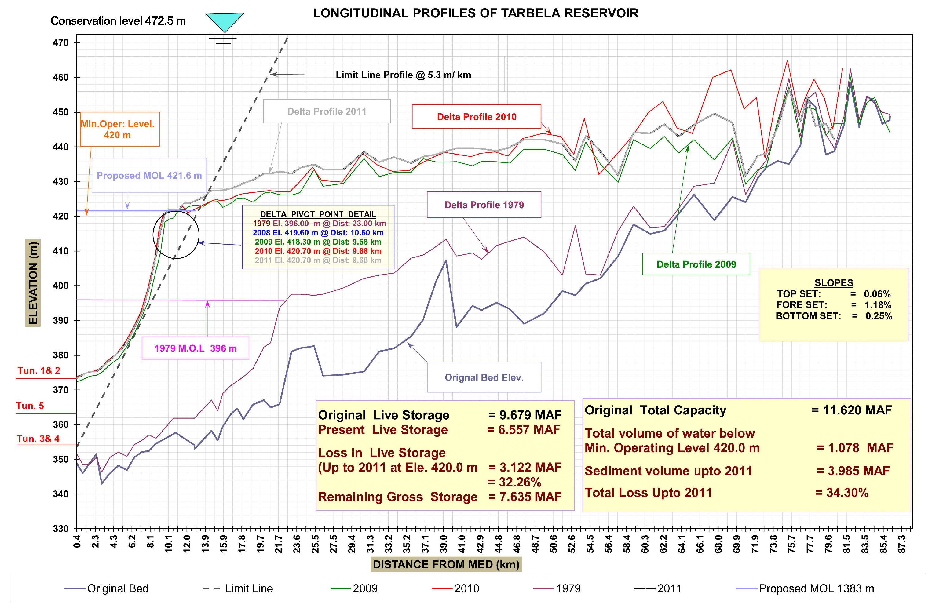
Ref. [9] noted that from 1969–2008 the annual sediment inflows into the reservoir varied between 92–270 Mt, which reduced the water storage capacity by 35% (Figure 2) by 2011. The decrease in the storage capacity is a concern as it could result in reduction of irrigation supplies/allocations as per the Historic Apportionment Accord signed between the provinces in 1991 [29] and power supply. In addition, the impact of a delta created by the sediment deposits approaching the main dam is likely to block the power intakes. A recent alarming event at the Tarbela occurred in summer season of 2018 when reservoir levels dropped considerably, resulting in temporary blockage of power intakes. As the storage capacity of the reservoir reduces, more sediment will pass through the power intakes and likely to damage the turbine blades/runners. The problems may also be aggravated by the instability of the downstream sloping face of the delta [30] coupled with an occurrence of a earthquake [28].

2.2. Data Description

The available sediment transport data for the dam consists of a long-term hydrological database of published annual suspended sediment records and hydrographic surveys conducted each year since 1983 (first comprehensive survey after the dam’s construction in 1974). The hydrographic surveys are conducted using a systematic sounding method along the 73 cross sectional range lines, which covers the whole dam area, i.e., 161 km2. Approximately 3500–4000 measurements of the bed level changes, water depths, and water surface elevations along these range lines are available, which were mostly collected during each survey conducted from September to November. The distance between the cross sections (range lines) and the (measured) data points along these cross sections is not uniform. An average distance between each cross section along the river thalweg is approximately 1.16 km. However, compared to the upstream (upper periphery of the reservoir), the distances between the cross sections are smaller near the dam. The distance between the measured data points along the cross sections (lateral distance in y direction) also varies with a mean of 39 m. The mean cross sectional width near the dam axis is approximately 4–5 km, which reduces to only 300–500 m at the upper periphery. Therefore, the major ponding area is near the dam axis and contains huge sediment deposits (Figure 2).
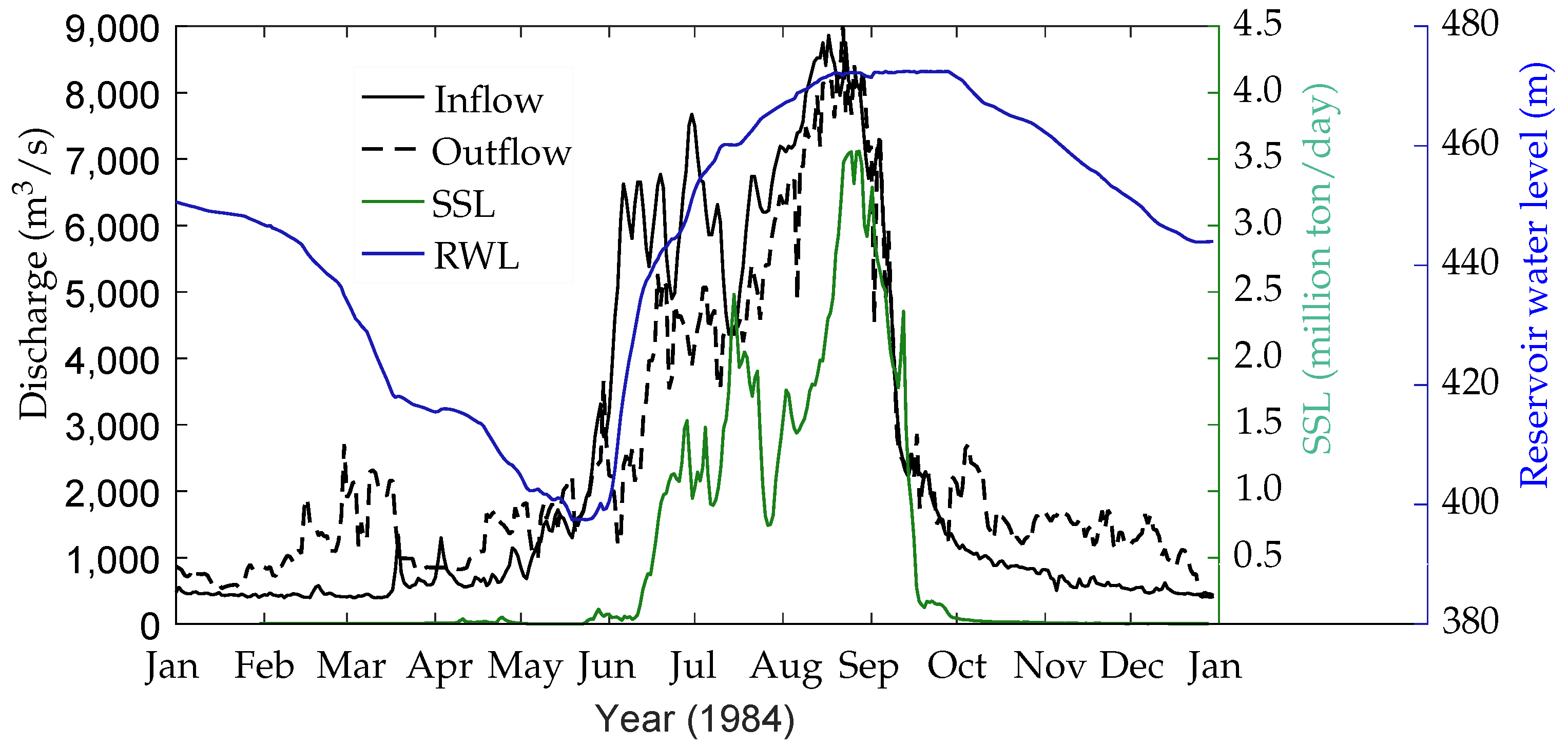
Long-term continuous discharge and discontinuous suspended sediment concentration (SSC) sampling data is available at Besham Qila, which functions as an inflow gauge station for the Tarbela dam. On average, the SSC sampling frequency at the Besham Qila gauge station is 22% of annual daily sampling, therefore a daily time scale can be established using a sediment rating curve or an ANN and WA-ANN techniques [9]. In the present study, we used a WA-ANN technique from [11] study, which reconstructed the SSLs with Nash–Sutcliffe Efficiency (NSE) = 0.837 for the calibration and NSE = 0.871 for the validation period (Table 1). The Indus River transports more silt (47%) compared to sand and clay (Table 2), and 90% of it is trapped in the dam [31]. The density of sand, silt and clay is 1535, 1330, and 1170 kg/m3. However, observations show that there is no clear boundary of sizes between cohesive and non-cohesive sediments, the definition of cohesive sediment is usually site specific. Normally, cohesion plays a significant role for sediment sizes smaller than 2 m in reservoirs (including the Tarbela). We, therefore, used cohesionless modelling [31,32,33]). Most of the transport processes occur in the summer months; 84% of the total annual discharge and 99% of the SSL transport occur from May to September (Table 3, Figure 3).
Water depth in the reservoir varies from a maximum 150 m near the main dam to mostly 20 m upstream. To secure the stability of the dam and the slopes on both banks along the reservoir, the maximum lowering and rising rate for the reservoir during operation, is 4 m/day and 3 m/day, respectively, between reservoir levels 396–460 m and only 1 m/day up to the maximum conservation level (472.5 masl). The average slope upstream of the delta of the river bed in 1979 was 1 m 892 m , which became flatter in 2010, with an average slope of 1 m 1670 m . More detail on data availability, data quality, re-construction and distribution can be found in [9,11,34].

2.3. Model System

TELEMAC is an open source finite element flow model on an unstructured, triangular mesh [35], whereas SISYPHE is a sediment transport model, which is capable of modelling sedimentary systems containing very fine to medium sand in suspension or as bedload [36]. Both models provide the opportunity to the users to adapt and modify the codes to facilitate a better simulation performance. In addition, the software package programmed for the parallel processing option, which significantly reduces the simulation time of study domains, has enormous mesh nodes. The opportunity to modify the source code also allows for implementing an automatic calibration concept using Matlab (R2016a and R2018a developed by MathWorks) or other programming languages. Different numerical schemes are available which can be selected according to study requirements, available computational power, time availability and desired accuracy. However, an edge based N-scheme based on a positive depth algorithm is a good compromise between accuracy and computational time [36]. The scheme is stable for the Courant number during each time step where it remains less than 1. Calculating a fixed time step over which the Courant number always stay below 1 is, nevertheless, challenging. Therefore, a variable time step option can be used where the model automatically executes intermediate time steps and the Courant number stays below a given value. The variable time step option is useful for simulations over several years or decadal, during which a river catchment undergoes several dry and wet hydrological cycles of run-off and subsequent sediment load.
The main factors controlling the sand transport are: advection by currents, settlement under gravity, turbulent diffusion in all directions, and exchange of sand between the flow and the bed. Two methods, chaining or internal coupling, are used to link the hydrodynamic and morphodynamic models [36]. In chaining, both hydrodynamic and morphodynamic models perform independently. For morphodynamic calculations the flow field is obtained from a previous hydrodynamic simulation where the bed is assumed to be non-moveable. Due to the difference in time scales of hydrodynamics and bed evolution, this coupling method is normally used to model simple flows and small bed changes. The chaining coupling method does not conserve the mass due to change in the flow field while the bed evolves, which can lead to numerical instability. In internal coupling, the models communicate through a quasi-steady morphodynamic time stepping approach and both models (TELEMAC and SISYPHE) can be run fully coupled in such a way that after TELEMAC has computed the flow, the flow field can be used at each time step by the SISYPHE to calculate the sediment transport and resulting changes in the bed. The new bathymetry is passed back to the TELEMAC to calculate the new flow field on the next time step. If the flow is stationary and the bed changes in a time step are small compared to the water depth, a morphological speed up is used to reduce the computational time [36,37,38,39,40].

2.3.1. TELEMAC-2D for Hydrodynamics

The TELEMAC 2D solves the following 2D shallow water equation for hydrodynamics. The equations were derived from the Navier–Stokes equations by taking the vertical average:
h t + ( h u ) x + ( h v ) y = 0 ,
( h u ) t + ( h u 2 ) x + ( h u v ) y = h g Z s x + τ x x ρ ,
( h v ) t + ( h v 2 ) y + ( h u v ) x = h g Z s y + τ y y ρ ,
where h = depth of water (m); u , v = depth-averaged flow velocity components in x and y direction, respectively (m/s); g = gravitational acceleration (m/s2); Z s = free surface elevation (m); t = time (s); x, y = horizontal Cartesian coordinates (m); ρ = density of water (kg/m3); τ x x and τ y y = depth-averaged turbulent stresses. The bed shear stress is represented as a quadratic function of velocity:
τ b ( x , y ) = ρ C f ( u , v ) | u | 2 ,
where C f is roughness coefficient which can be calculated using Manning (n: m 1 / 3 s ), Chezy (C: m s ), or Nikuradse (N: mm) equations.

2.3.2. SISYPHE for Morphodynamics

The sediment transport model, SISYPHE, simulates river bed morphodynamics by calculating temporal changes in bed elevation Z b using the Exner equation:
( 1 p ) Z b t + ( δ b c b ) t + ( q t , x ) x + ( q t , y ) y + η e η d = 0 ,
where Z b = bed elevation (m); δ b = bed load layer thickness (m); p = bed porosity (-); c b = sediment concentration in bed load layer (m3/m3); q t , x = total sediment transport in x-direction (m2/s); q t , y = total sediment transport in y-direction (m2/s); η e , η d are erosion and deposition rates, respectively (m/s).
The SISYPHE model assumes the Rouse concentration profile, from which the equilibrium depth-averaged concentration is calculated.

2.4. Model Setup

2.4.1. Grid Mesh

The geometry of the Tarbela dam reservoir area was drawn from the Tarbela Reservoir Sedimentation survey conducted in 1983. The survey along the Indus River was conducted from dam axis (0 km) to 88.10 km upstream. The reservoir bathymetric survey conducted by the Water and Power Development Authority Pakistan (WAPDA) proceeded from the left river bank to the right river bank, while looking downstream. The y distance (m) along each cross section starts from the left river bank (with an absolute value of zero) to a maximum at the right river bank. The x distance (m) along the river starts from the main dam axis (central line) to a maximum at upstream (upper periphery of the reservoir (88.10 km)). The z is the river reservoir bed elevation in meters above sea level (masl) at each x and y distance. At each cross section, there was information of the distance along the left river bank, the distance along the main river channel (centre line), and the distance along the right river bank, i.e., at each cross section three values of x-distance. All measurements of z at each cross section were between the left and right river bank. On average, 47 measurements were taken on each of the 73 cross sections, which resembles a total of 3455, excluding the cross section (R/line) 62, where no data is available for 1983 (see Figure 4). We excluded the Siran and Brandu tributaries (due to their minor contribution in the Tarbela dam) from the reservoir geometricmodel. To create the geometry, SMS 12.2.9 developed by the Aquaveo and the open source software BlueKenue was used. In order to convert the local coordinates of the data points on each cross section to global coordinates (Cartesian coordinate system), the y distance was transformed with AutoCAD Civil 3D 2018 (Figure S1). The final geometry applied in the numerical model is shown in Figure 4.
An unstructured mesh of various sizes, particularly a finer one for the areas where the river meanders, was generated. The final mesh contains 138,000 mesh elements representing 171 km2. In selecting cell resolution, we tried to achieve a reasonable compromise between accuracy and computational time.
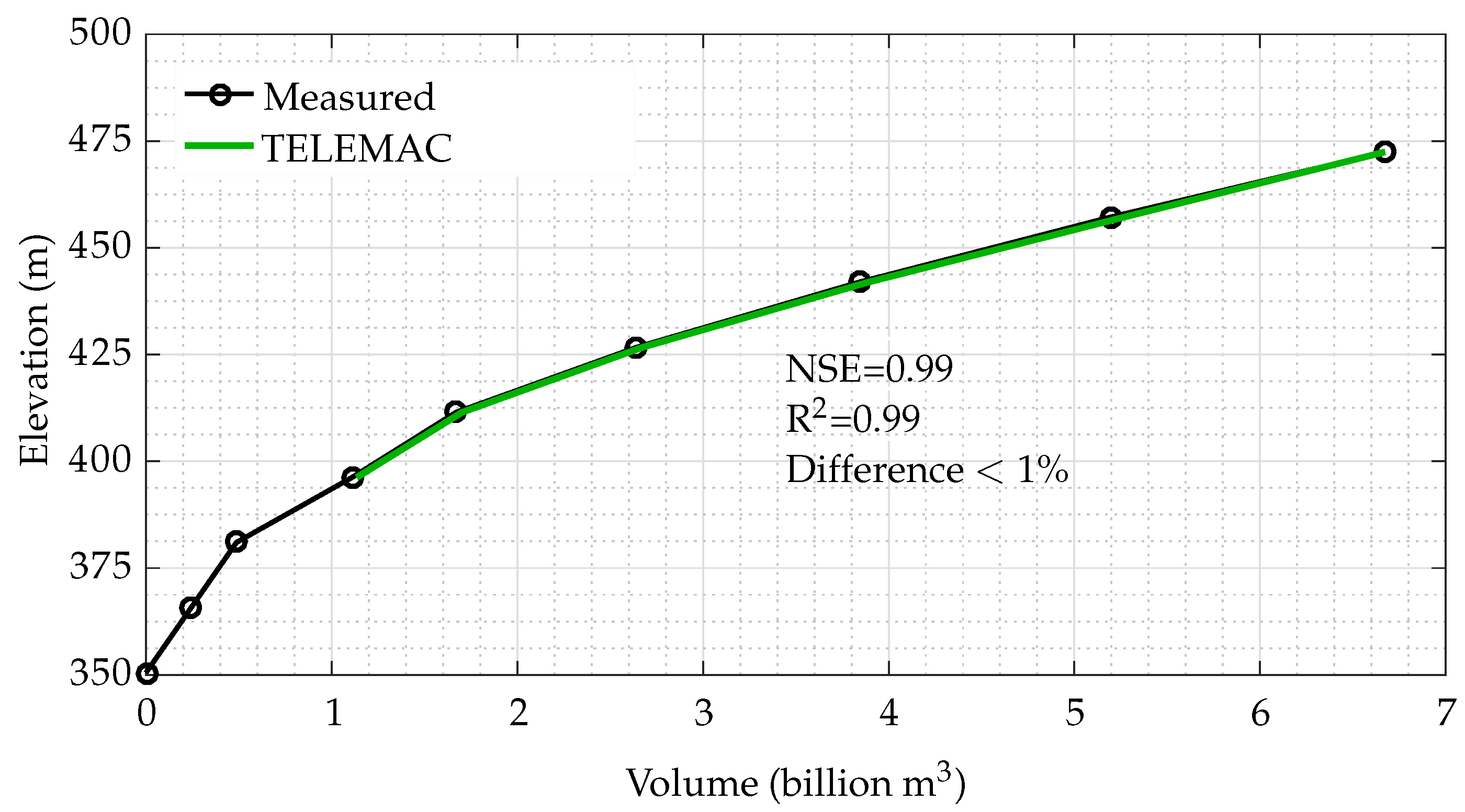
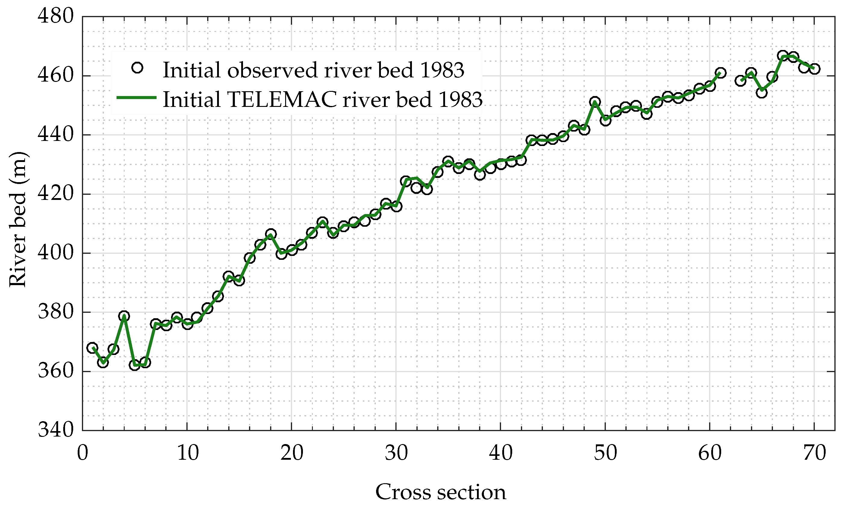
To confirm the geometry approximation, we compared elevation-storage volume curve with the observation (which does not include the volumes of the Siran and the Brandu tributaries) as shown in Figure 5. We obtained the statistical performance parameters NSE = 0.99, R2 = 0.99, and a relative difference between the measured and the computed volume = 1%. Furthermore, the longitudinal profile of the mean measured and calculated river bed is also shown in Figure 6. The results confirmed a correct representation of the grid mesh used in the numerical model.

2.4.2. Initial and Boundary Conditions

As an initial condition, we filled the reservoir up to the maximum conservation level, i.e., 472.5 m, so that the model can attain a stable condition at the beginning. In addition, we also set the SSC in equilibrium. In the numerical model, the vertical variations in the SSCs and river flow were considered small compared to their horizontal counter parts. The daily measured discharges and the WA-ANN reconstructed suspended sediment loads (SSLs) were applied as upstream boundary conditions while the reservoir water levels (RWL) were kept as the downstream boundary condition. We used the data from 1983 for hydrodynamic calibration while the data from 1984 to 1985 were used for the morphodynamic calibration and from 1985 to 1990 for the validation. We also omitted the low flow periods (from November to March (Table 3)) from the modelling due to their small contribution in the annual SSLs [11]. We also excluded small tributaries, i.e., the Siran and the Brandu, due to their minor (0.04% and 0.16%) contribution to the total sediment load entering the Tarbela Reservoir [31].

2.5. Model Performance

To evaluate the performance of the TELEMAC/SISYPHE model in terms of accuracy and consistency in predicting reservoir water depths and bed levels, the three following statistical measures were employed: (a) coefficient of determination (R2), which is an index of the degree of relationship between the observed and simulated data, ranging from 0 to 1, as follows:
R 2 = i = 1 P ( X i o b s X ¯ o b s ) ( X i s i m X ¯ s i m ) i = 1 P ( X i o b s X ¯ o b s ) 2 i = 1 P ( X i s i m X ¯ s i m ) 2 2 ,
where X i o b s , X i s i m represent ith value of observed and simulated parameters, respectively, where X ¯ denotes their mean values.
(b) Observations standard deviation ratio (RSR), which is the ratio of root mean square error (RMSE) and standard deviation (STDEV) of the observed data, as follows:
RSR = RMSE S T D E V o b s = 1 P i = 1 P ( X i o b s X i s i m ) 2 i = 1 P ( X i o b s X ¯ o b s ) 2 .
RSR varies from 0 to any positive value. A lower RSR value indicates a better performance of the model simulation.
(c) Nash–Sutcliffe Efficiency (NSE), which is a statistical measure to determine the relative magnitude of the residual variance compared to the measured data variance [41], as follows:
N S E = 1 i = 1 P ( X i o b s X i s i m ) 2 i = 1 P ( X i o b s X ¯ o b s ) 2 .
Although negative values are possible, the NSE generally ranges from 0 to 1. NSE = 0 indicates that the model is no better than simply forecasting the mean value. The closer the value of NSE to 1, the better the model performance. The simulated results are normally referred as good when the NSE is higher than 0.75 and satisfactory when it lies between 0.36 to 0.75 [42]. To define a stopping criteria (Equation (17)) for hydrodynamic calibration, we assigned equal weight to all three statistical parameters in the form of a statistical mix (S) as follows:
S = R 2 + ( 1 RSR ) + NSE 3 .
S can vary from 1 to a negative value, where 1 indicates a best performance of the model.

2.6. Model Parameters and Automatic Calibration

The information about the Tarbela dam other than daily inflows, reservoir water levels, and WA-ANN reconstructed SSLs are:
  • volume of sediments deposited each year after the flood season (between October–November),
  • 72 longitudinal profiles along the reservoir over the period 1983 to the present,
  • composition of the sediment deposits in some areas,
  • flow velocities measured with an ADCP at several cross sections,
  • outflow discharge and sediment concentration.
This information was used for hydrodynamic and morphodynamic calibrations. The automatic calibration algorithm was developed to save computational time. We edited and controlled the TELEMAC and SISYPHE models with a single Matlab code (Figure 7).
The TELEMAC and SISYPHE models required specifying several parameters such as a method for parametrising fraction coefficients, initial particle size distribution, sediment transport (suspended and bed load) formulae, critical Shield parameter, and settling velocity. For the suspended sediment calculations, we tested different transport formulae. The critical Shield parameter was set to 0.047 for the simulations. We provided settling velocities (m/s) to the model using the following Equation [43,44]:
W s = ( s 1 ) g d 50 2 18 ν , if d 50 10 4 , 10 ν d 50 1 + 0 . 01 ( s 1 ) g d 50 3 18 ν 1 , if 10 4 d 50 10 3 , 1 . 1 ( s 1 ) g d 50 , otherwise .
To deal with limitation of the numerical scheme, which can arise due to a numerical error and can create negative water depths, we specified a minimum water depth of 1 cm in the whole study domain. As the Indus River has an alluvial bed, we specified an erodible layer thickness of 100 m. The Manning roughness (n) was calculated using a back propagation error method (discussed below).
Based on preliminary results for the morphodynamic calibrations, we eventually used the [43] suspended sediment transport formula (Equation (11)) with different reference elevations ( Z r e f ) by changing total bed roughness ( k s ). We also tested different friction angles and bedform correction factors for the sediment transport in the calibration process:
C e q = 0 . 015 d 50 × ( τ τ c r 1 ) 0 . 66 Z r e f × D * 0 . 3 ,
where τ c r is critical shear stress (N/m2), D * is dimensionless grain diameter, Z r e f is reference elevation which can be calculated after [43] using m a x ( k s 2 ; 0 . 01 m ) , while k s is total bed roughness (m) and is obtained from hydrodynamic calculations (Equation (16): friction coefficients from hydrodynamic results) and type of bed-forms (flat, smooth or ripples bed). The τ is total shear stress (N/m2) includes skin friction which can be calculated using Equation (12):
τ = μ × τ b ,
where τ b is total bed shear stress and μ is bed form coefficient calculated as follows:
μ = C f C f ,
where C f is the combined friction of both drag forms and skin friction, and can be obtained from hydrodynamic results. C f is a friction coefficient due to skin friction and can be calculated as follows:
C f = 2 × k l o g ( 12 × h k s ) 2 ,
where k is von Karman coefficient(=0.40), and k s is roughness height and can be computed as:
k s = α k s × d 50 ,
where α k s is a calibration coefficient and d 50 mean particle diameter (m). Although the shallowness assumption is compromised due to non hydrostatic pressure distribution near the main dam, to model the bed level changes in the dam ponding area on a large scale, we assumed that pressure distribution is virtually hydrostatic [24]. More details on morphodynamic calculations of the SISYPHE model can be found [36].
The Manning roughness (n) is used as one of the key parameters for flow calibration. The hydrodynamics was calibrated using the observed water levels at different locations along the 72 cross sections from 1983. The morphodynamics were calibrated using the river bed level changes along these cross sections from 1985. To compare the measurements (3455) in the calibration process, we created a 2D surface, to obtain interpolated values at the measured locations, by interpolating the simulated results using a 2D interpolation method. Based on the comparisons between the simulated and measured values, the relevant hydrodynamic and morphodynamic parameters were updated (Figure 7). For interpolation, we used:
  • linear,
  • nearest point,
  • natural, and
  • cubic
interpolation methods.
Initially, for hydrodynamic calibration, a constant hydraulic roughness n = 0.04 from the literature [18,22,45] was used for the whole domain. In successive simulations, the model calculated n for each node using a backward error propagation method stated in Equation (16):
n i , n o d e = n i 1 , n o d e n i 1 , n o d e × P i 1 , n o d e × K , P i 1 , n o d e = 2 1 + e ( 2 × η i 1 , n o d e ) 1 , where   1 P + 1 , η i 1 , n o d e = d i 1 , n o d e o d i 1 , n o d e s d i 1 , n o d e o , where   i = 2 , 3 , . . , m ,
where m represents numbers of simulations, d o represents observed and d s simulated water depths (m), and η is a dimensionless gradient used to arrive an optimal n. P is used to avoid over-or-undershoots of n. K is used to curtail significant changes in n due to continuous large gradients η at certain nodes. In subsequent iterations, the roughness to unmeasured nodes/points was assigned using a 2D linear interpolation method. The model stops when the difference between successive statistical mix (S) is a minimum, given here:
S i S i 1 0 . 0001 ,
where S is given in Equation (9). The convergence depends on the selection of an initial value of n.

3. Results

For the computational grid mesh, we used 1983’s comprehensive dam bathymetric survey. To calibrate the TELEMAC 2D model (with an automatic calibration algorithm), we use the hydrological data from 1985. To calibrate the SISYPHE model, we used the bathymetric survey from 1985. To validate the morphodynamic calculations, we use the bathymetric survey from 1990. The simulation results were evaluated using the coefficient of determinations (R2), observed standard deviation ratio (RSR), and Nash–Sutcliffe Efficiency (NSE). The results are discussed in detail below.

3.1. Model Calibration

Since a better representation of the study domain in the form of a numerical mesh plays a significant role in subsequent calculations, we tested different types of mesh sizes to obtain realistic results. Based on difference between measured and simulated water depths, we calibrated the hydrodynamic model by updating Manning roughness (n) for the whole domain using an automatic calibration approach mentioned above (Figure 7). The calibrated flow model was used further for calibrating and validating morphodynamics as well as applying to predict (up to 2030) the bed level changes in the reservoir using more precise sediment load boundary conditions reconstructed with a WA-ANN (for WA-ANN model development please see [11]). The overall performance of the modelling concept was assessed using three statistical performance parameters, i.e., R2, RSR, and NSE. The hydro-morphodynamic results of the study are described below.
To obtain the simulated water depths at the measured points, we applied a 2D scatter data interpolation method. The method interpolates the surface and returns the interpolated values at the desired points (x,y). The surface always passes through the mesh data points. In our study, we tested four different interpolation methods, namely,
  • linear,
  • nearest point,
  • natural, and
  • cubic.
Due to the smooth river bed along the cross sections in the Tarbela Reservoir, a linear interpolation performed better than the other mentioned methods. Therefore, by using linear interpolation, we compared the interpolated and measured depths and updated n in the whole study domain using a back propagation method (Equation (16)). The final roughness (n) ranged from 0.035 to 0.045 with a mean of value of 0.0395. The roughness was lower downstream near the dam and in the middle of the channel, and vice versa (Figure 8).
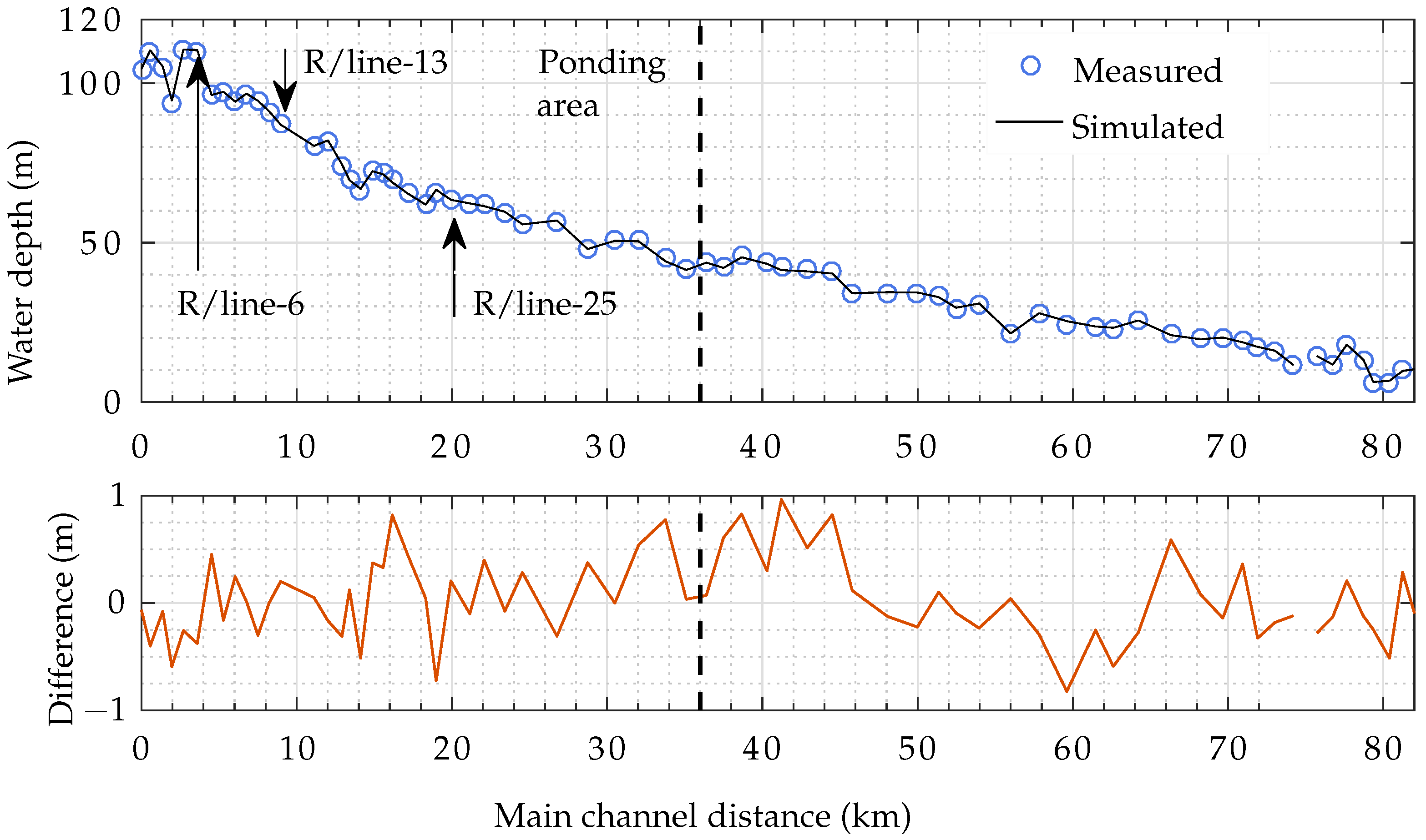
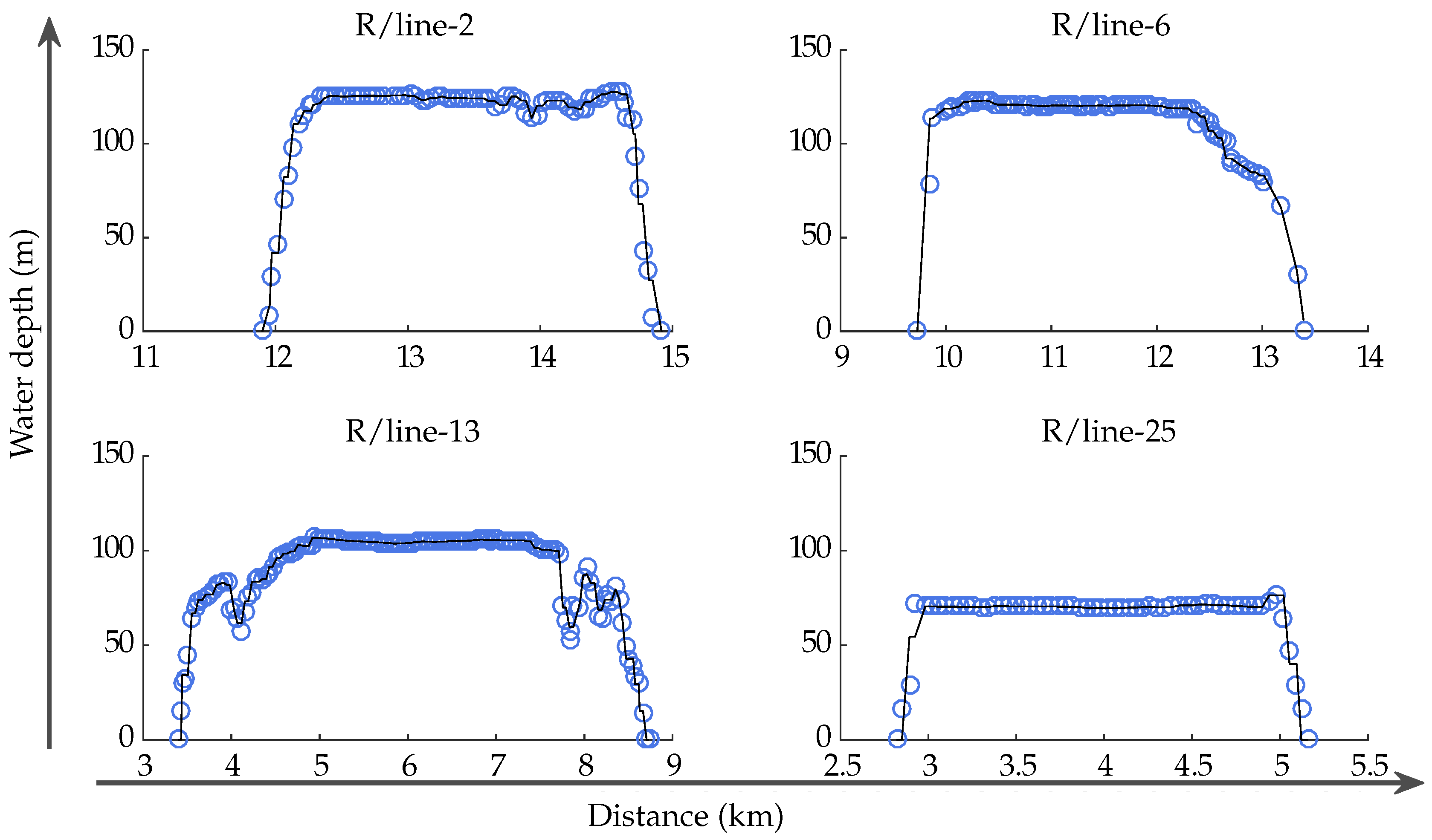
Initially, using a uniform value of n = 0.04, we obtained an absolute average difference of 1.6 m between the simulated and measured water depths. However, the difference decreased to only ±1 m after five iterations. The mean relative difference between the simulated and measured data points was only 0.072%. At some cross sections, we only have measurements near the river banks, which is why their mean appears lower than neighbouring cross sections (Figure 9). Comparison of water depths at some selected cross sections is shown in Figure 10.
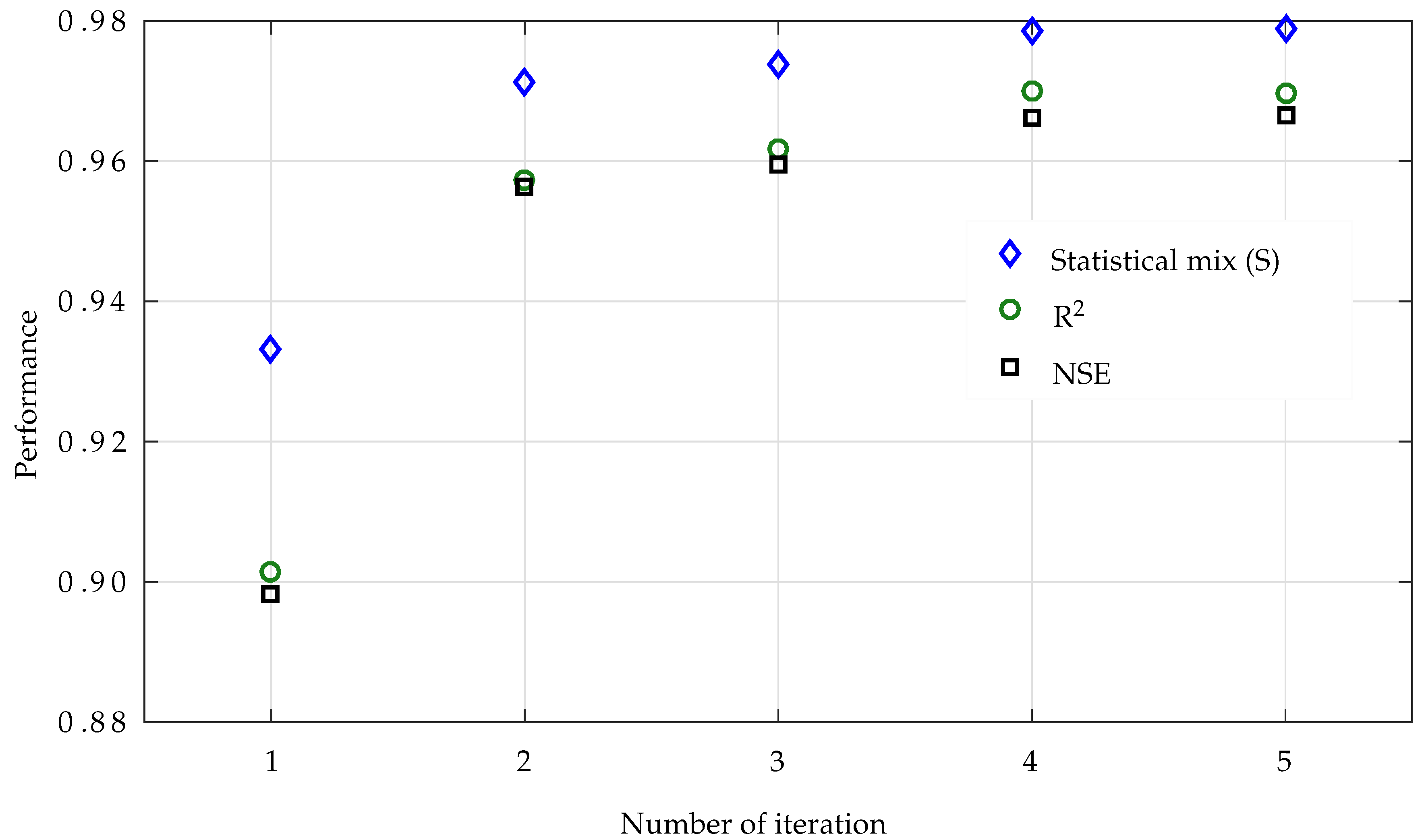
Water depth convergence depends upon an initial estimate of n. Using a single roughness (n = 0.04) from the literature [18,22,45] for the whole domain of 171 km2, initially, we obtained a statistical mix (S) = 0.933, R2 = 0.90, and NSE = 0.898 (Figure 11). The performance of the model increased to a statistical mix = 0.978, R2 = 0.969, and NSE = 0.966 by iterating n for each node point as per Equation (16) and the process stated in Figure 7. The approximated computational time in each simulation was 12–15 h using a server with 20 physical cores (dual Intel XEON E5-2687W v3 @ 3.1 GHz) and 128 GB of RAM. Due to the large standard deviation (33.9 m) and small RMSE (0.0988) in the water depths, the observation standard deviation ratio (Equation (7)) remained in the range of 10 3 in all five simulations.
Furthermore, we used the calibrated flow model for morphodynamic calibration and validation. As 90% of the sediment load (SL) entering the dam consists of suspended load [11,34], we omitted bed load from the modelling process. For SL concentration, we used [43] formula (Equation (11)). The bed roughness was updated using a skin correction factor in the formula. The calibrated coefficient α k s = 3 (Equation (15)) provided the best results.
By varying different parameters (such as reference elevation, total roughness, etc.), we conducted a number of different simulations until a good agreement between the measured and simulated result was found as presented in Table 4. We also updated the TELEMAC/SISYPHE 2D code for all fractions of suspended SL boundary conditions. In addition, the negative depth which arose due to numerical error was solved by specifying a minimum water depth of 1 cm in the whole study domain. However, this overall minimum water depth caused an excessive clay deposition due to its very low settling velocity = 2 × 10 5 m/s at some nodes on high river banks. We solved this issue by specifying no SL transport at equal or less than 1 cm water depth. Our final simulated results from May 1984 to October 1985 showed R2 = 0.97, RSR = 0.36%, and NSE = 0.96 (Figure 12). There was only 0.76% difference between the simulated and measured deposits in the reservoir. However, the mean differences between the simulated and observed river bed was in the range of −5 to 7 m.
Figure 12 compared the mean computed and observed river bed along the river reach. The disagreement between measured and simulated results at some cross sections located in the upstream part of the river may be caused by large distance between the measured cross sections in this part of the river, distorting the in-between initial geometric information (see Figure 4).
There was also a good agreement between each measurement along the cross sections in the ponding area (Figure 13), where the Tarbela Reservoir has a sediment delta (Figure 2). The approximated computational time in each simulation from 1983–1985 for only high flows (March to September—Table 3) was one week. After calibrating the model, we used the 1985 simulated river bed for the validation process.

3.2. Model Validation

We validated the model using the sedimentation survey conducted in 1990, which (including cross section (R/line) 62) has 3600 measured points of the river bed elevation along 73 cross sections. For validation, we ran the model for the five years (1986–1990) and compared the measured and simulated river bed elevations. The statistical comparison showed R2 = 0.96, RSR = 0.37%, and NSE = 0.95, whereas the difference between the measured and simulated deposits was only 0.54%. Similar to the morphodynamic calibration, the mean differences between the simulated and observed river bed were in the range of −5 to 7 m (Figure 14).
As with the longitudinal profile in the calibration process, we obtained good results for the ponding area (Figure 14). However, there were also disagreements between the measured and simulated results at some cross sections located upstream of the ponding area. In conformity with the calibration results, the model provided the results close to river bed elevations measured along the cross sections in the ponding area (Figure 15). The approximated computational time in each simulation from 1983–1990 for only high flows (March to September—Table 3) was three weeks.

3.3. Model Application

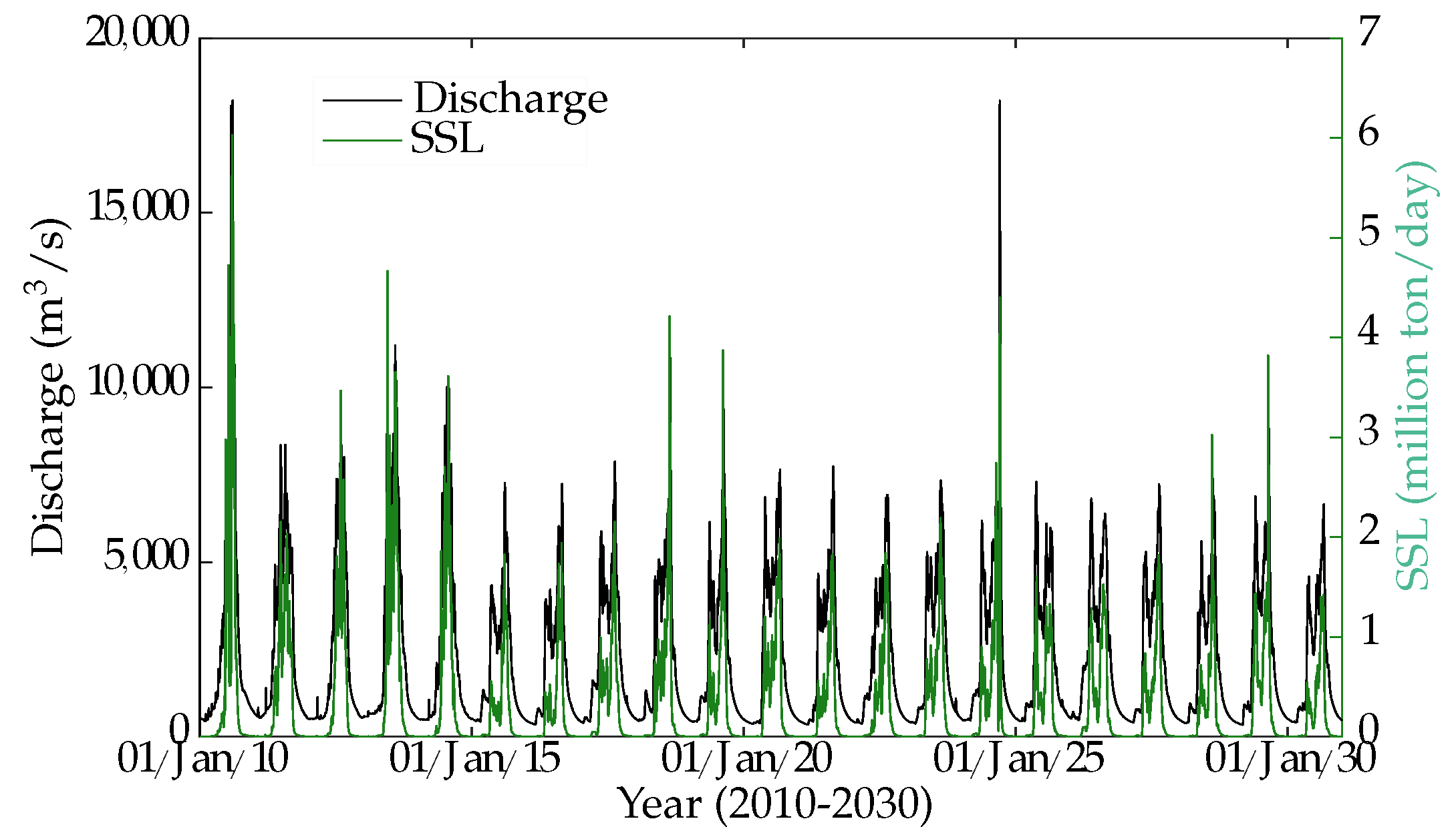
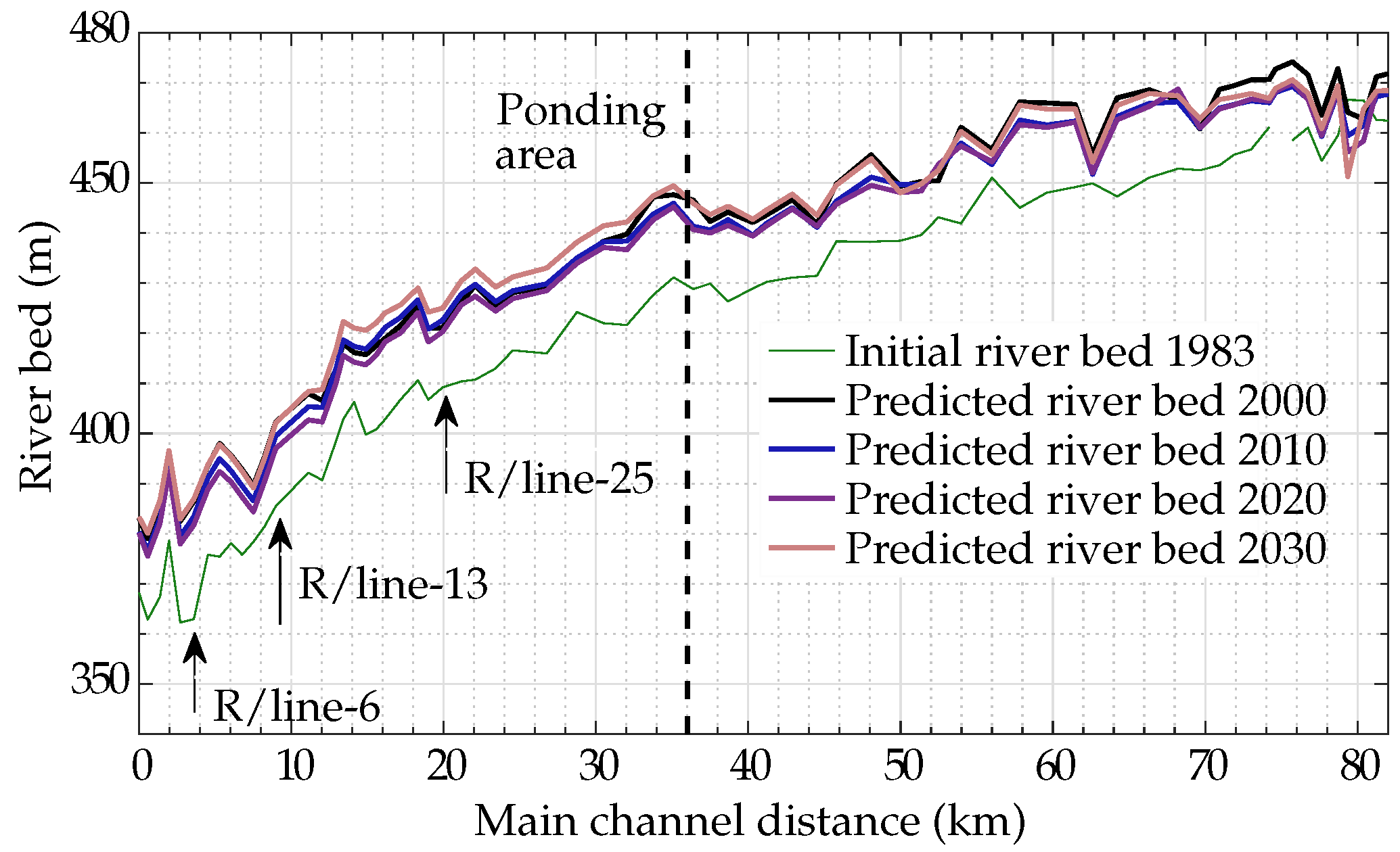
Since the people, economy and agriculture of the Pakistan rely heavily on the water supply from the Tarbela Reservoir, the current and future state of river discharges and corresponding water storage are a matter of high political sensitivity due to climate change [47]. The political tensions over water availability are further exacerbated by existing dwindling and planned storages. Hence, to evaluate the effect of sediment transport variability on the reservoir sedimentation and water storage, we applied a future discharge series for (2016–2030) calculated by [48] and corresponding SSLs estimated using WA-ANN [9,11] (Figure 16). The reservoir water levels from 2016–2030 were kept the same as 2000–2015. The near future scenarios of WA-ANN estimated sediment load suggest a substantial decrease (20 million tons (Mt)) caused by a drop in the glacier melt and one month delay in peak of flows and overall reduction in water availability. The mean annual sediment load (SL) from 1969–2008 was 160 Mt with a mean annual discharge of 76 billion m3 [11]. However, the mean SL from 2000–2008 was decreased to 146 Mt/year with a mean discharge of 75 billion m3/year. Near future projections from 2010–2030 also suggest a further decrease to 120 Mt/year with a mean discharge of 75 billion m3/year. These disproportional spatio-temporal trends between SL and discharges are primarily caused by intra-annual shifts in flow discharges from summer to the winter under the influence of warmer climates [11,48]. Our modelling results also showed a stability in sediment delta development due to an average 17% decrease in sediment supply in the near future (Figure 17). However, the overall water availability is expected to slightly decrease in the future, and the significant decrease in sediment load can help to store more water for multi-purpose use (irrigation, hydropower, etc.) and was likely to increase the life span of the reservoirs.

4. Discussion

The automatic hydrodynamic calibration algorithm for the Tarbela dam improved the model performance from R2 = 0.90 and NSE = 0.898 to R2 = 0.969, and NSE = 0.966 (Figure 11). In addition, more precise sediment load (SL) boundary conditions obtained using the wavelet artificial neural network (WA-ANN) calibrated the model with R2 = 0.97 and NSE = 0.96 (Figure 12). The model validated the results by predicting the reservoir bed for five years (1986–1990) with R2 = 0.96 and NSE = 0.95 (Figure 14). Although the overall statistical performance of the model was good, it also over-predicted the river bed (0.76%) in the calibration process, particularly upstream of the ponding area (Figure 12). However, the over-predictions were reduced to an average 0.54% in the validation process (Figure 14). The calculations for bed level changes in the ponding area, particularly for the sediment delta, were close to the measurements in both the calibration and validation processes (Figure 13 and Figure 15). In addition, our modelling also shows a stability in the sediment delta development due to significant decrease (17%) in near future sediment load entering the reservoir (Figure 16 and Figure 17).
The back propagation method has been successfully used in the training of artificial neural networks for hydro-sedimentological studies [49,50]. Using the same method along with a 2D linear interpolation during calibration process, we were able to update and interpolate the Manning roughness (n) for each node of the mesh. To achieve this, the TELEMAC model passed the hydrodynamic information (water depths) to Matlab, which was compared with the observations in the form of matrices (Figure 7). The difference was used to update n for the whole mesh using the linear interpolation method. The overall set-up not only reduced the computational effort but also saved computational time by using calculations in a more systematic way. Therefore, we were able to reduce the difference between predictions and measurements in only five iterations (Figure 11) by employing the stopping criteria defined in Equation (17), i.e., the difference between successive statistical mix (S) should be equal or less than 0.0001. The fast convergence with the minimum possible number of iterations not only saved computational effort but also provided us with an opportunity to curtail circular error in subsequent morphodynamic calculations. Fast convergence within minimum possible iterations is always required where large water bodies such as the Tarbela Reservoir (having hundreds of thousands of mesh nodes) are being simulated, which requires huge computational effort. Although the bed roughness has comparatively less influence in high water depths such as in the Tarbela (water depth approx. 100 m), the automatic calibration algorithm can also be used effectively in low water depth channels/rivers, where the influence of roughness on hydrodynamic parameters is high.
The more precise SL boundary conditions also improved the subsequent performance of SISYPHE calculations for bed level changes. In particular, the bed level changes in the ponding area, which contained the sediment delta. As the sediment delta progresses downstream towards the main dam, a precise representation of the delta in the modelling process can provide a better understanding of the impact of different management options necessary to preserve the functionality of the dam. In addition, the calibration period (1984–1985), which represents both dry and wet hydro-sedimentological events, favoured good calibration. Consequently, during the testing/validation period (1986–1990), which also contains the second highest flow and SL year (from 1969–2008), the model performed well. Therefore, the representativeness of the data sets used for calibration and validation should be considered because, when the model is calibrated with a data set that represents, the characteristics of the hydro-sedimentological patterns will achieve good matching.
Although in terms of calculating total roughness using the [43] formula (Equation (11)) the automatic hydrodynamic calibration has improved the morphodynamic calculations by specifying the roughness for each mesh node, the main factors that influence reservoir sedimentation are:
  • inflow of both discharges and SLs,
  • particle size distribution of sediments,
  • specific weight of sediment deposits,
  • geometry of the reservoir, and
  • reservoir operation rules [51].
The influence of these factors may vary prior to river and locational characteristics. Despite the fact that all these factors are to some extent uncertain, and also cause uncertainty in the model outcome, the inflow discharges and SLs are the most important factors contributing to the variation of accumulating sediments in the reservoirs [52]. Measurements taken twice daily successfully reduced the uncertainties in inflow discharge at Besham Qila. However, occasional/non-daily SSC sampling still contributed to variation in accumulating sediments in the Tarbela Reservoir, particularly when the occasional measurements were transferred on a daily time scale using conventional sediment rating curves. In a recent study, Ref. [22] modelled the Tarbela’s delta using a 1D HEC-6 model. There was an average variation of 20 m (just in one year) between the observed and simulated river bed at some cross sections (during validation) in the dam ponding area. This variation could relate to uncertainty in sediment load (SL) boundary conditions, which were estimated using a sediment rating curve (SRC). The SRC has limited accuracy since it does not adjust complex sediment transport processes related to hysteresis phenomena and temporary sediment storage in the Upper Indus River [11]. For example, the mean deviation between the predicted SL using SRC and the measurements conducted for the Tarbela over a period of 26 years was as high as approximately 40%. However, using SL boundary conditions, estimated using the WA-ANN model, the variation was reduced to a range of −5 to 7 m (using TELEMAC/SISYPHE 2D model for seven years) in the same domain (Figure 12 and Figure 14). In another study, Ref. [25] used a TELEMAC 2D model to assess the impact of sediment distribution on the life of the Hirakud reservoir in India. The model slightly overestimated the deposits at the inlet due to sudden expansion of inlets, which reduced the water velocities, turbulences and shear stresses, and caused a delta there. However, with NSE = 0.51 to 0.77, the model reasonably represented the overall changes in the bathymetry of the reservoir using daily measured sediment concentrations as SL boundary conditions. Therefore, the more precise modelling of reservoir sedimentation significantly depends on the quality of the input parameters and representation of geometry in the form of a numerical mesh. The use of a 2D model not only helps to design correct reservoir operation rules for the flushing of sediments but also contributes to diminishing circular error, particularly in the presence of complex topography, where 2D models can provide more accurate predictions in detail.
Interestingly, a slight decrease in near future discharges caused by delaying glacier melt [48] is stabilizing the sediment delta by decreasing sediment supply to the Indus River at Tarbela dam (Figure 16 and Figure 17). Compared to an initial estimates by [53] of 480 million tons/year (Mt/year) or by [54] of 400 Mt/year at the time of Tarbela’s construction, the sediment load in 2020 to 2030 will remain only at 120 Mt/year. This is mainly caused by a desynchronization between the glacier melt (major source of the flow discharges) and monsoon rain, which will result in a subsequent decrease in peaks flows and cause to reduced sediment transport due to decrease in effective discharges—the most effective discharge is defined as a midpoint of the range of flows, which, over a certain period, can transport a considerable proportion of the SSL [55]. Although current findings contradict the previous claims of high reservoir sedimentation due to climate change [3,56], the desynchronization has a positive effect on the life span and higher storage capacities of planned hydraulic structures on the Indus River. Additionally, the drop in short future sediment loads also negates the previous reservoir sedimentation studies, which simply used the past hydro-meteorological data without modification to the future predictions, particularly for the hydropower projects planned in the Indus River/Basin [17,19,20,21,22].
Despite the fact that the SISYPHE predictions for bed level changes in the Tarbela Reservoir are close to our measurements, omission of low flow/SL months from October to April (Table 3), when reservoir water levels are reduced to the minimum level (Figure 3), might have affected trap efficiency calculations and caused a 0.5–0.8% over-prediction. However, to compute seven years (1983–1990, only high flows and SLs) of reservoir sedimentation required a three-week simulation time using a server with 20 physical cores (dual Intel XEON E5-2687W v3 @ 3.1 GHz) and 128 GB of RAM. To save computational time and assess the effects of only significant SL contributing periods, we decided to omit the low flow months from the modelling process.
The overall modelling approach can be used for better design of planned hydraulic structures and existing ones in the Indus Basin, particularly in the Upper Indus Basin, where the Tarbela dam is used as a standard/reference point for reservoir sedimentation studies of 30,000 MW planned hydraulic structures. In the absence of any hydraulic structure or land use changes in the Upper Indus River/Basin, there are statistically significant trends in discharges and SLs. Our cascade modelling approach using future SL can also be used to improve sediment management strategies and update reservoir operation rules for hydraulic structures. The SL boundary conditions for predictions can be estimated using WA-ANN models and future discharges. A coupling of the TELEMAC/SISYPHE model with a 1D model can reduce computation time, which could be useful for longer-range predictions.

5. Conclusions

In this paper, the uncertainty factor related to sediment load (SL) boundary conditions were diminished using WA-ANN and TELEMAC-SISYPHE models, respectively. The flow model was calibrated using an automatic calibration algorithm along with more precise suspended SL boundary conditions. To predict the sediment delta movement in the ponding area, a hydrological and WA-ANN models were used to obtain the future discharge and corresponding sediment load boundary conditions. Based on the study results, we can draw the following main conclusions:
  • More accurate WA-ANN estimated sediment load boundary conditions which better represent the hysteresis phenomenon and hydrological variations for the Indus River enabled the successive morphodynamic model to accurately predict the bed level changes in the Tarbela dam.
  • Automatically calibrating hydrodynamics improved the overall statistical performance and reduced the calculation time for long-term simulations. In addition, specifying the bed roughness for each mesh node using the back propagation error method subsequently enhanced the performance of morphodynamic calculations by providing better hydrodynamic variables and total bed roughness for the calculation of sediment erosion, transport and deposit in the flow area.
  • The desynchronization between glacier melt and monsoon rainfall due to warmer climate will also cause a significant decrease in future sediment loads and subsequent delta development. Therefore, past hydro-meteorological data (showing higher sediment loads) cannot be used without modification when making future predictions, particularly for the hydropower projects planned at the Indus River/Basin.
On the basis of these conclusions, we would make the following recommendations:
  • The presented modelling concept can be used to improve/design sediment management strategies for the existing and planned hydraulic structures in other non-gauged or poorly-gauged rivers.
  • Although the effect of the bed roughness on the water depths in large dams is not always dominant, the concept of an automatic hydrodynamic calibration can also be used for other water bodies where roughness has a significant influence on water depths.
  • In order to reduce computational time for long-term morphodynamic predictions, coupling of the TELEMAC 2D model with a 1D model/ANN is recommended.

Supplementary Materials

The following are available online at https://www.mdpi.com/2073-4441/10/10/1411/s1, Figure S1.

Author Contributions

S.A. designed the study, processed and analysed the data, interpreted the results, and wrote the paper. S.H. provided the hydrological model for future flow discharge predictions. M.D.B. and P.R. contributed to the model development stage with theoretical considerations and practical guidance, assisted in the interpretations and integration of the results, and helped in preparation of this paper with proofreading and corrections.

Funding

This research received no external funding.

Acknowledgments

The German Academic Exchange Service (DAAD) and Higher Education Commission (HEC) of Pakistan jointly financed this work. The Surface Water Hydrology Project (SWHP) of WAPDA provided the data. The German Research Foundation (DFG) and the Technical University of Munich (TUM) supported this work in the framework of the Open Access Publishing Program. We greatly appreciate their help. The first author is also grateful to Rohit Kumar, DNZE Munich, for his help. Shabeh ul Hasson also acknowledges the support of the Cluster of Excellence “CliSAP” (EXC177), University of Hamburg, funded through the German Science Foundation (DFG).

Conflicts of Interest

The authors declare no conflict of interests.

Abbreviations

ADCPAcoustic Doppler Current Profiler
BCMbillion cubic meter
c b sediment concentration in bed load layer
C e q equilibrium near-bed concentration
C f roughness coefficient
C f combined friction of both drag forms and skin friction
d 50 mean diameter
D * dimensionless grain diameter
d o observed water depth
d s simulated water depth
ggravitational acceleration
hwater depth
HEC-RASHydrologic Engineering Center-River Analysis System
kvon Karman coefficient
kmkilometre
k s bed roughness
k s roughness height
maslmean above sea level
Mtmillion ton
MWmegawatt
nManning roughness
NSENash–Sutcliffe Efficiency
p bed porosity
ppmpart per million
q t , x and q t , y total sediment transport in x and y direction
R2coefficient of determination
R/linerange lines or cross section
RESSASSReservoir Survey Analysis and Sedimentation Simulation
RSRobservations standard deviation ratio
RWLreservoir water level
Sstatistical mix
SLsediment load
SRCsediment rating curve
SSLsuspended sediment load
SSCsuspended sediment concentration
SUPGStreamline-Upwinded Petrov–Galerkin
ttime
u , v depth-averaged flow velocity components in x and y direction
ρ density
τ x x and τ y y depth-averaged turbulent stresses
δ b bedload layer thickness
η e erosion rate
η d deposition rate
X i o b s observed parameter
X i s i m simulated parameter
τ shear stress due to skin friction
τ c r critical shear stress
τ b total bed shear stress
μ bed form coefficient
α k s calibration coefficient
UIBUpper Indus Basin
W s settling velocity
WA-ANNwavelet artificial neural network
WAPDAWater and Power Development Authority
yryear
Z b bed elevation
Z r e f reference elevation
Z s free surface elevation

References

  1. Basson, G. Management of siltation in existing and new reservoirs. General Report Q. 89. In Proceedings of the 23rd Congress of the CIGB-ICOLD, Brasilia, Brazil; 2009. Available online: http://scholar.sun.ac.za/handle/10019.1/43104 (accessed on 5 October 2018).
  2. Annandale, G. Sustainable water supply, climate change and reservoir sedimentation management: Technical and economic viability. In Reservoir Sedimentation; Schleiss, A.J., Cesare, G.D., Franca, M.J., Pfister, M., Eds.; Taylor & Francis Group: London, UK, 2014; ISBN 978-1-138-02675-9. [Google Scholar]
  3. Schleiss, A.J.; Franca, M.J.; Juez, C.; De Cesare, G. Reservoir sedimentation. J. Hydraul. Res. 2016, 54, 595–614. [Google Scholar] [CrossRef]
  4. WAPDA. Tarbela Dam Project, Residency Survey and Hydrology Organization; Water and Power Development Authority: Lahore, Pakistan, 2017. [Google Scholar]
  5. Qiu, J. Stressed Indus River threatens Pakistan’s water supplies. Nature 2016, 534, 600–601. [Google Scholar] [CrossRef] [PubMed]
  6. Immerzeel, W.W.; Van Beek, L.P.; Bierkens, M.F. Climate change will affect the Asian water towers. Science 2010, 328, 1382–1385. [Google Scholar] [CrossRef] [PubMed]
  7. Pritchard, H.D. Asia’s glaciers are a regionally important buffer against drought. Nature 2017, 545, 169–174. [Google Scholar] [CrossRef] [PubMed]
  8. Nourani, V.; Baghanam, A.H.; Adamowski, J.; Kisi, O. Applications of hybrid wavelet–artificial intelligence models in hydrology: A review. J. Hydrol. 2014, 514, 358–377. [Google Scholar] [CrossRef]
  9. Ateeq-Ur-Rehman, S.; Bui, M.D.; Rutschmann, P. Development of a wavelet-ANN model for estimating suspended sediment load in the upper Indus River. Int. J. River Basin Manag. 2017. [Google Scholar] [CrossRef]
  10. Juez, C.; Hassan, M.A.; Franca, M.J. The origin of fine sediment determines the observations of suspended sediment fluxes under unsteady flow conditions. Water Resour. Res. 2018, 54. [Google Scholar] [CrossRef]
  11. Ateeq-Ur-Rehman, S.; Bui, M.D.; Rutschmann, P. Variability and trend detection in the sediment load of the Upper Indus River. Water 2018, 10, 16. [Google Scholar] [CrossRef]
  12. Lutz, A.F.; Immerzeel, W.W.; Shrestha, A.B.; Bierkens, M.F.P. Consistent increase in High Asia’s runoff due to increasing glacier melt and precipitation. Nat. Clim. Chang. 2014, 4, 587–592. [Google Scholar] [CrossRef]
  13. Khan, F.; Pilz, J.; Amjad, M.; Wiberg, D.A. Climate variability and its impacts on water resources in the Upper Indus Basin under IPCC climate change scenarios. Int. J. Glob. Warm. 2015, 8, 46–69. [Google Scholar] [CrossRef]
  14. Lutz, A.F.; Immerzeel, W.; Kraaijenbrink, P.; Shrestha, A.B.; Bierkens, M.F. Climate change impacts on the upper Indus hydrology: Sources, shifts and extremes. PLoS ONE 2016, 11, e0165630. [Google Scholar] [CrossRef] [PubMed]
  15. Khan, F.; Pilz, J.; Ali, S. Improved hydrological projections and reservoir management in the Upper Indus Basin under the changing climate. Water Environ. J. 2017, 31, 235–244. [Google Scholar] [CrossRef]
  16. Brune, G.M. Trap efficiency of reservoirs. Trans. Am. Geophys. Union 1953, 34, 407–418. [Google Scholar] [CrossRef]
  17. Dasu Hydropower Consultants. Detailed Engineering Design Report, Part A; Engineering Design; Water and Power Development Authority: Lahore, Pakistan, 2013. [Google Scholar]
  18. Dasu Hydropower Project. Dasu Hydropower Project, Feasibility Report; Water and Power Development Authority: Lahore, Pakistan, 2009. [Google Scholar]
  19. Bunji Consultants Joint Venture. Bunji Hydropower Project, Design Report, Volume 2B Sedimentation; Water and Power Development Authority: Lahore, Pakistan, 2010. [Google Scholar]
  20. Roca, M. Tarbela Dam in Pakistan. Case study of reservoir sedimentation. In Proccedings of River Flow; Munoz, R.E.M., Ed.; CRC Press: London, UK, 2012; ISBN 978-0-415-62129-8. [Google Scholar]
  21. Ateeq-Ur-Rehman, S.; Riaz, Z.; Bui, M.D.; Rutschmann, P. Application of a 1-D numerical model for sediment management in Dasu Hydropower Project. In Proccedings of the 14th International Conference on Environmental Science and Technology; Lekkas, D., Ed.; Global CEST: Rohdes, Greece, 2015; ISBN 978-960-7475-52-7. [Google Scholar]
  22. Rehman, H.U.; Rehman, M.A.; Naeem, U.A.; Hashmi, H.N.; Shakir, A.S. Possible options to slow down the advancement rate of Tarbela delta. Environ. Monit. Assess 2018, 190. [Google Scholar] [CrossRef]
  23. Malik, Y.I.; Munir, J. Hydraulic design of the low level outlets for Dasu dam, Pakistan. Int. J. Hydropower Dams 2011, 18, 41. [Google Scholar]
  24. Rüther, N. Computational Fluid Dynamics in Fluvial Sedimentation Engineering. Ph.D. Thesis, Fakultet for Ingeniørvitenskap og Teknologi, Trondheim, Norway, 2006. [Google Scholar]
  25. Dutta, S.; Sen, D. Sediment distribution and its impacts on Hirakud Reservoir (India) storage capacity. Lakes Reserv. Res. Manag. 2016, 21, 245–263. [Google Scholar] [CrossRef]
  26. Reisenbüchler, M.; Bui, M.D.; Rutschmann, P. Implimentation of a new layer-subroutine for fractional sediment transport in SISYPHE. In XXIIIrd TELEMAC-MASCARET User Conference; Bourban, S., Ed.; HR Wallingford Ltd.: Howbery Park, Wallingford, UK, 2016. [Google Scholar]
  27. The International Journal on Hydropower & Dams. First power from Tarbela IV in Pakistan. Int. J. Hydropower Dams 2018, 25, 15. [Google Scholar]
  28. TAMS Consultants and HR Wallingford. Tarbela Dam Sediment Management Study; Main Report; Water and Power Development Authority: Lahore, Pakistan, 1998. [Google Scholar]
  29. Anwar, A.A.; Bhatti, M.T. Pakistan’s water apportionment Accord of 1991:25 years and beyond. J. Water Resour. Plann. Manag. 2018, 144. [Google Scholar] [CrossRef]
  30. Lowe, J.; Fox, I. Sedimentation in Tarbela Reservoir, Commission Internationale des Grandes Barrages. Quatorzieme Congres des Grands Barrages: Rio de Janeiro, 1982. Available online: http://www.icold-cigb.net/homefr.asp (accessed on 5 October 2018).
  31. Ali, K.F. Construction of Sediment Budgets in Large Scale Drainage Basins: The Case of the Upper Indus River. Ph.D. Thesis, Department of Geography and Planning, University of Saskatchewan, Saskatoon, SK, Canada, 2009. [Google Scholar]
  32. Mehta, A.J.; Lee, S.C. Problems in linking the threshold condition for the transport of cohesionless and cohesive sediment grain. J. Coast. Res. 1994, 10, 170–177. [Google Scholar]
  33. Klassen, I. Three-Dimensional Numerical Modeling of Cohesive Sediment Flocculation Processes in Turbulent Flows. Ph.D. Thesis, Bauingenieur-, Geo- und Umweltwissenschaften, Karlsruher Instituts für Technologie (KIT), Baden-Württemberg, Germany, 2017. [Google Scholar]
  34. Ali, K.F.; De Boer, D.H. Spatial patterns and variation of suspended sediment yield in the Upper Indus River Basin, northern Pakistan. J. Hydrol. 2007, 334, 368–387. [Google Scholar] [CrossRef]
  35. EDF-R&D. TELEMAC v7.0 User Manual; Open TELEMAC-MASCARET: Chatou, France, 2014. [Google Scholar]
  36. EDF-R&D. Sisyphe v7.2 User’s Mannual; Open TELEMAC-MASCARET: Chatou, France, 2017. [Google Scholar]
  37. Roelvink, J.A. Coastal morphodynamic evolution techniques. Coast. Eng. 2006, 53, 277–287. [Google Scholar] [CrossRef]
  38. Duc, B.M.; Bernhart, H.H.; Kleemeier, H. Morphological numerical simulation of flood situations in the Danube River. Int. J. River Basin Manag. 2005, 3, 283–293. [Google Scholar] [CrossRef]
  39. Juez, C.; Murillo, J.; Garcia-Navarro, P. A 2D weakly-coupled and efficient numerical model for transient shallow flow and movable bed. Adv. Water Resour. 2014, 71, 93–109. [Google Scholar] [CrossRef]
  40. Reisenbüchler, M.; Bui, M.D.; Skublics, D.; Rutschmann, P. An integrated approach for investigating the correlation between floods and river morphology: A case study of the Saalach River, Germany. Sci. Total Environ. 2019, 647, 814–826. [Google Scholar] [CrossRef] [PubMed]
  41. Nash, J.E.; Sutcliffe, J.V. River flow forecasting through conceptual models part I—A discussion of principles. J. Hydrol. 1970, 10, 282–290. [Google Scholar] [CrossRef]
  42. Moriasi, D.N.; Arnold, J.G.; Van Liew, M.W.; Bingner, R.L.; Harmel, R.D.; Veith, T.L. Model evaluation guidelines for systematic quantification of accuracy in watershed simulations. Trans. Asabe 2007, 50, 885–900. [Google Scholar] [CrossRef]
  43. Rijn, L.C.V. Sediment transport, part II: Suspended load transport. J. Hydraul. Eng. 1984, 110, 1613–1641. [Google Scholar] [CrossRef]
  44. Van Rijn, L.C. Principles of Sediment Transport in Rivers, Estuaries And Coastal Seas; Aqua publications Amsterdam: Amsterdam, The Netherlands, 1993; ISBN 9080035629. [Google Scholar]
  45. HR Wallingford. Sedimentation Study, Dasu Hydropower Project; Report EX 6801 R1; Dasu Hydropower Consultants; Water and Power Development Authority: Lahore, Pakistan, 2012. [Google Scholar]
  46. Talmon, A.M.; Struiksma, N.S.; van Mierlo, M.C.L.M. Laboratory measurements of the direction of sediment transport on transverse alluvial-bed slopes. J. Hydraul. Res. 1995, 33, 495–517. [Google Scholar] [CrossRef]
  47. Bolch, T. Hydrology: Asian glaciers are a reliable water source. Nature 2017, 545, 161–162. [Google Scholar] [CrossRef] [PubMed] [Green Version]
  48. Hasson, S. Future water availability from Hindukush-Karakoram-Himalaya Upper Indus Basin under conflicting climate change scenarios. Climate 2016, 4, 40. [Google Scholar] [CrossRef]
  49. Rumelhart David, E.; McClelland, J.L. Parallel Distributed Processing, v. 1, Foundations Explorations in the Microstructure of Cognition Foundations; MIT Press: Cambridge, UK, 1986. [Google Scholar]
  50. Jain, S.K. Development of integrated sediment rating curves using ANNs. J. Hydraul. Eng. 2001, 127, 30–37. [Google Scholar] [CrossRef]
  51. USBR. Design of Small Dams; Water Resources Technical Publication: New York, NY, USA, 1987; 860p. [Google Scholar]
  52. Salas, J.D.; Shin, H.S. Uncertainty analysis of reservoir sedimentation. J. Hydraul. Eng. 1999, 125, 339–350. [Google Scholar] [CrossRef]
  53. Holeman, J.N. The sediment yield of major rivers of the world. Water Resour. Res. 1968, 4, 737–747. [Google Scholar] [CrossRef]
  54. Peshawar University. The Sediment Load and Measurements for Their Control in Rivers of West Pakistan; Department of Water Resources, Peshawar University: Peshawar, Pakistan, 1970. [Google Scholar]
  55. Pickup, G. Adjustment of stream-channel shape to hydrologic regime. J. Hydrol. 1976, 30, 365–373. [Google Scholar] [CrossRef]
  56. Kumar, R.; Kumar, R.; Singh, S.; Singh, A.; Bhardwaj, A.; Kumari, A.; Randhawa, S.S.; Saha, A. Dynamics of suspended sediment load with respect to summer discharge and temperatures in Shaune Garang glacierized catchment, Western Himalaya. Acta Geophys. 2018, 66, 1–12. [Google Scholar] [CrossRef]
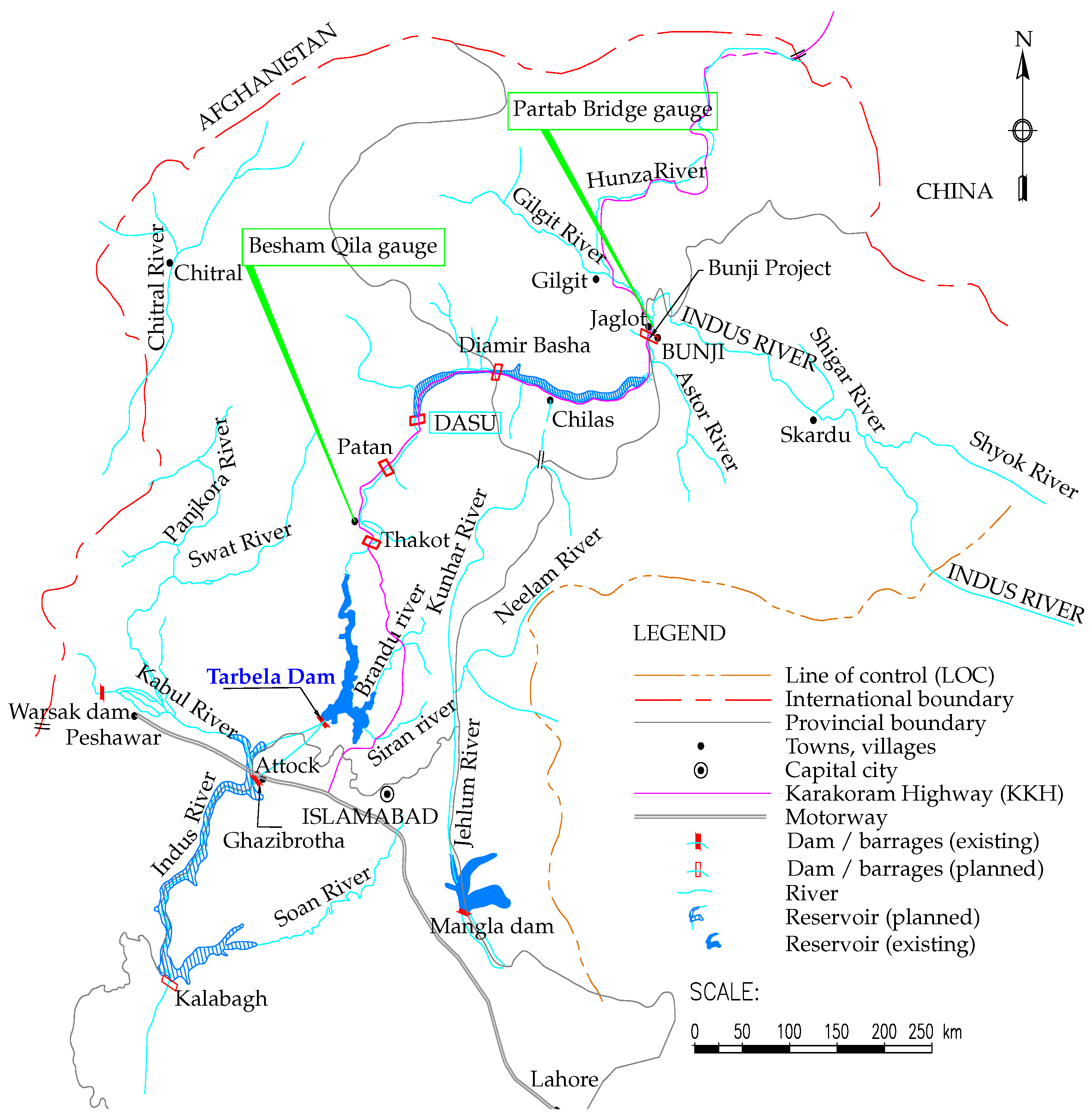
Figure 1. Location map of the study area, modified from [17].
Water 10 01411 g001
Figure 2. Sediment delta development in the Tarbela dam.
Water 10 01411 g002
Figure 3. Sediment inflow, reservoir water level and discharges in 1984 (dash line represents outflow from the dam).
Water 10 01411 g003
Figure 4. Measured data points (grey) along cross sections/range lines and TELEMAC simulated water depth at 30 September 1983.
Water 10 01411 g004
Figure 5. Comparison between the computed elevation-storage volume and observation for 1983.
Water 10 01411 g005
Figure 6. Mean observed and approximated river bed.
Water 10 01411 g006
Figure 7. Algorithm for model calibration. The algorithm for TELEMAC and SISYPHE works in an uncoupled way where morphodynamic calibration only start after hydrodynamic calibration finished.
Water 10 01411 g007
Figure 8. Interpolated Manning roughness (n). Grey lines represent the measurements along the cross sections/range lines (R/line).
Water 10 01411 g008
Figure 9. Comparison of mean measured and computed water depths at each cross section.
Water 10 01411 g009
Figure 10. Comparison between measured (circles) and simulated water depths at selected cross sections (R/line) for 1983’ event. Measurements starts from the orographically left side of the reservoir.
Water 10 01411 g010
Figure 11. Statistical convergence of water depths for 1983’ event.
Water 10 01411 g011
Figure 12. Longitudinal profile of mean measured and computed river bed at the end of the calibration process.
Water 10 01411 g012
Figure 13. Comparison between measured and simulated river bed at four selected cross sections/range lines (R/line) at the end of calibration process. Measurements start orographically from the left side of the reservoir.
Water 10 01411 g013
Figure 14. Longitudinal profile of mean measured and computed river bed at the end of the validation process.
Water 10 01411 g014
Figure 15. Comparison between measured and simulated river bed at four selected cross sections (R/line) at the end of the validation process. Measurements start orographically from left side of the reservoir.
Water 10 01411 g015
Figure 16. Predicted flow discharge and sediment load at the Tarbela dam.
Water 10 01411 g016
Figure 17. Longitudinal profile of predicted river bed using WA-ANN predicted sediment boundary conditions.
Water 10 01411 g017
Table 1. Statistical performance of WA-ANN for reconstructing SSL in study period (only high flows from May to September). Sediment load was calculated in [11].
ProcessDurationR2RSRNSE
Calibration1984–19850.8420.0190.837
Validation1986–19900.8880.0190.871
Table 2. Mean representative size classes of SSC.
Sand
Grain size (mm)1.00.50.250.1250.0625Pan
Fraction (%)10099.8796.9885.8571.9871.97
Silt
Grain size (mm)0.04420.03120.02210.01560.0110.0078
Fraction (%)64.5157.1249.5941.0732.7025.29
Clay
Grain size (mm)0.00550.0039
Fraction (%)17.4310.32
Table 3. Suspended sediment load and flow volume distribution in million tons (Mt) and billion cubic meters (BCM) from 1984–1990. Outflow also includes the minor contribution (0.04% and 0.16%) of the Siran and Brandu tributaries.
MonthsAverage SSL (Mt)Average inflow (BCM)Average outflow (BCM)
Jan–Apr0.985.6711.85
May–Sep157.965.5455.18
Oct–Dec1.115.5011.25
Table 4. Formulae and value of different hydro-morphodynamic parameters (stated in Equations (10)–(16)) used in the calibration process.
ParameterValue/methods
Hydrodynamics
Numerical schemeCentred semi implicit scheme plus SUPG
Solver for hydrodynamic propagation stepGeneralized minimum residual method
EquationsSaint-Venant finite element
Hydrodynamic calibration factor (K)1.0
Manning roughness (n)0.035–0.045
Mean Manning roughness (n)0.0395
TELEMAC and SISYPHE model couplingInternal
Morphodynamics
Bed porosity ( p )0.375
Fluids viscosity ( ν ) 1 × 10 6
Suspended sediment transport formula[43]
Calibration coefficient ( α k s )3
von Karman coefficient (k)0.40
Shields parameter0.047
Friction angle of sediment ( ϕ s )32
Minimum depth required for sediment transport1 cm
Formula for deviation[46]
Parameter for deviation ( β 2 ) [46]0.85
Stream wise slope effect ( β )1.3
Solver for suspensionConjugate gradient
Critical evolution ratio0.5
Numerical treatment of the advection termEdge-based N-scheme