Article

The Role of Attenuation and Land Management in Small Catchments to Remove Sediment and Phosphorus: A Modelling Study of Mitigation Options and Impacts

1
School of Engineering, Newcastle University, Newcastle Upon Tyne NE1 7RU, UK
2
Department of Geography, Durham University, Durham DH1 3LE, UK
*
Author to whom correspondence should be addressed.
Water 2018, 10(9), 1227; https://doi.org/10.3390/w10091227
Submission received: 22 August 2018 / Revised: 3 September 2018 / Accepted: 10 September 2018 / Published: 12 September 2018
(This article belongs to the Special Issue Modeling and Practice of Erosion and Sediment Transport under Change)

Abstract

:
It is well known that soil, hillslopes, and watercourses in small catchments possess a degree of natural attenuation that affects both the shape of the outlet hydrograph and the transport of nutrients and sediments. The widespread adoption of Natural Based Solutions (NBS) practices in the headwaters of these catchments is expected to add additional attenuation primarily through increasing the amount of new storage available to accommodate flood flows. The actual type of NBS features used to add storage could include swales, ditches, and small ponds (acting as sediment traps). Here, recent data collected from monitored features (from the Demonstration Test Catchments project in the Newby Beck catchment (Eden) in northwest England) were used to provide first estimates of the percentages of the suspended sediment (SS) and total phosphorus (TP) loads that could be trapped by additional features. The Catchment Runoff Attenuation Flux Tool (CRAFT) was then used to model this catchment (Newby Beck) to investigate whether adding additional attenuation, along with the ability to trap and retain SS (and attached P), will have any effect on the flood peak and associated peak concentrations of SS and TP. The modelling tested the hypothesis that increasing the amount of new storage (thus adding attenuation capacity) in the catchment will have a beneficial effect. The model results implied that a small decrease of the order of 5–10% in the peak concentrations of SS and TP was observable after adding 2000 m3 to 8000 m3 of additional storage to the catchment.

Graphical Abstract

1. Introduction

It is becoming widely accepted that Nature Based Solutions (NBS—Nature Based Green Instructure Solutions) [1] and “Natural Flood Management” (NFM) (defined by the United Kingdom Environment Agency as part of Working with Natural Processes) [2] can have a positive impact in terms of reducing flooding, most observably by lowering the peak discharge of the flood hydrograph to enable this [3,4,5,6,7]. The construction of different types of “soft engineered” measures (or features) in headwater catchments has become an established part of this strategy [2,8]. Previous studies of the performance of features have concentrated primarily on the attenuation capabilities of these features in terms of reducing flooding, e.g., Belford Burn [9] and Pickering Beck [4,10] (in the U.K.). Moreover, the improvement in water quality (quantifiable by a reduction in concentrations and/or loads of nutrients and sediments) brought about by the construction of features in rural catchments has been studied in the U.K. [11,12,13], Irish Republic [14], and in New Zealand [15], but this issue has generally received less attention than the mitigating benefits of NFM in terms of reducing storm events.
Avery [16] coined the term “rural sustainable drainage systems” (RSuDS) to reflect the trend to construct wetlands and other types of features in rural catchments, and since the focus of this study is on the use of mitigation features to improve water quality rather than NFM per se, the term RSuDS henceforth is not used. The term “runoff attenuation feature” (RAF) has also been used in the literature [9,11]; essentially, an RSuD is a type of RAF that adds attenuation to a ditch or channel in which it is constructed [8]. However, the design purpose of RSuDs by default leads to sediment trapping and P stripping and associated “buffering” of other chemicals and microbial pollutants. Therefore, their ability to store and hence attenuate larger flood flows is lower. Often RAFs are designed to target flood flows primarily and thus the ideal solution is to both trap sediment and attenuate larger flow. This study explores the key role of adding attenuation to a catchment to target both water quantity and quality issues.
Environmentalists are interested in spatial patterns because they are essential in the scaling-up from localised measurements to larger spatial scales in order to provide assessments of mitigation impacts on pollution at the catchment, regional, or national scale for policy purposes [17]. In terms of addressing the impacts of mitigation features, few studies have attempted to assess the effect of mitigation features at the catchment scale [18]. These impacts have often been monitored by local water sampling and the measurement of runoff entering and leaving the features. For example, water quality, sediments, and nutrients have commonly been measured by automatic water quality samplers in order to collect data on concentrations and (if flow was measured) loads [12]. However, an important research question still remains as to whether impacts measured at the experimental scale are observable downstream, where monitoring points are often located (e.g., U.K. Environment Agency weekly sampling sites). Longer term monitoring programs (e.g., the Irish Agricultural Catchments (IAC) programme [19] and the Demonstration Test Catchments (DTC) programme [20,21]) are required if the larger scale impacts of these features are to be detected, if this is indeed possible with existing monitoring networks, and to address climatic issues (e.g., floods and droughts). Thus, the evidence that shows the rewards of adding attenuation capacity to a catchment are needed by end users, which is one goal of the DTC programme [21].
It is known from measuring water levels to observe runoff events before and after their construction that mitigation features have the potential to add attenuation to ditches and/or headwater streams [4,5]. These features can either: (i) divert water from channels via draw-off structures to separate storage areas or disconnected channels (classified as “off-line”), or (ii) temporarily detain runoff using “in-line” interventions located within low-order streams and ditches [11]. In-line features involve direct intervention in the channel or ditch itself such as the creation of artificial barriers, such as large woody debris (LWD) and engineered log jams (ELJs), and can also be applied in combination with off-line features [22]. Off-line features include riparian buffer strips, swales (vegetated channels), and ponds [5,13,23].
In terms of sediments and nutrients (principally total phosphorus (TP) and suspended sediment (SS)), the evidence from the case studies [11,24] is that these mitigation features can trap significant quantities of particulates with attached, insoluble forms of P. However, Barber [11] stated that few studies [13,23,25] had addressed either the effectiveness of mitigation features at the catchment scale, and suggested that, in order to address the requirement for urgent action with respect to meeting water quality targets in U.K. agricultural catchments, further research was required.
The natural attenuation of SS and bound nutrients, including forms of nitrogen (N) and P in riparian channel systems, is less-widely studied; however, one U.S. study [26] did highlight an important ecosystem function where the channels retained N and P exported from row crop fields during baseflow conditions, thus preventing higher exports into the estuary downstream in their catchment located in South Carolina, USA.
The primary aim of the study is to address the impacts of land management by altering hydrological flow paths and the overall catchment attenuation capacity on flow rates and nutrient losses. The modelling study described below demonstrates whether the impact of adding mitigation features, i.e., RAFs, at the headwater scale can be observable further downstream at a larger measurement scale. This modelling allows an estimate of how much attenuation can be achieved and the corresponding loss of productive land that may be required. A secondary aim is to explore whether the chosen model can simulate improvements to land management in a catchment that are designed to reduce losses of sediment and P in surface runoff. A further important research question poses: “Are there any significant differences in the performance of different types of features?” This can be limited by the available data on the performance of mitigation features [11,24].
A modelling case study to pursue the above aims used data collected from a catchment-based field programme in northern England [11,24] to parameterise the Catchment Runoff Attenuation Flux Tool (CRAFT) [27,28]. Scenarios were considered where: (i) RAFs were simulated by the model (by adding attenuation storage and trapping sediment and associated particulate forms of P) in order to see if the first aim can be achieved by investigating the impact on both the runoff hydrographs and the time series of P and SS concentrations modelled at the catchment outlet and also at the outlet of a mitigated sub-catchment, and (ii) land management options are applied instead to the same sub-catchment in order to reduce surface runoff from fields in the catchment and associated losses of sediment and particulate forms of P in surface runoff.

2. Methods

The methodology underpinning this study can be summarized by the following steps:
  • Develop the CRAFT model (at Newcastle University, Newcastle Upon Tyne, UK) to simulate nutrient and sediment fluxes at the catchment scale and add the capability to attenuate these fluxes in the surface runoff [27,28].
  • Calibrate the CRAFT to the existing runoff, nutrient, and sediment data collected in October 2011–September 2012 and establish a baseline scenario [28].
  • Evaluate the performance of a series of demonstration RAFs in the Mitigation sub-catchment of the NBC (mass of sediment and P trapped) [24] and use the information to inform the future scenarios.
  • Run simulations of the NBC using CRAFT with additional attenuation to represent three scenarios of land management.
  • Interpret the results of these scenarios in terms of (i) local and catchment scale impacts on runoff, TP, and SS; and (ii) compare the modelled changes in TP and SS yield with the measured reductions from step 3.

2.1. Description of the CRAFT

The Catchment Runoff Attenuation Flux Tool (CRAFT) [27,28] was selected for the case study. In this study, use was made of the model’s attenuation store, which attenuates the surface runoff generated from rainfall excess. The store is connected, therefore, to only one of the three runoff pathways in CRAFT [27]. The store mimics the physical processes of attenuation using the minimum information requirement [29] (MIR approach) in this case by utilizing a linear storage–discharge relationship [28]. The attenuation storage depth was calculated by the model at each timestep so the total volume of storage in the catchment was obtained by multiplying this by catchment area. It was necessary to specify the maximum storage depth in the model. If the depth in the store exceeded this value, then the excess runoff was added to the outflow from the store. The rate of drainage of the attenuation store was controlled by the KLAG parameter; this is equivalent to the reciprocal of lag time 1/k in the storage discharge relationship for a linear routing model (S = kQ) [30].
In terms of definitions of various P species, the CRAFT can output the following forms of P: particulate (insoluble, unreactive) P (PUP), particulate (insoluble, reactive) P (PRP), soluble reactive P (SRP) in groundwater, and fast subsurface flow. Therefore, in terms of the modelled concentrations and fluxes the P forms are combined so that: TRP = PRP + SRP and TP = TRP + PUP.

2.2. Description of Case Study

The catchment modelled in the case study (Newby Beck) is one of the three instrumented during the EdenDTC project, located in the River Eden catchment in northwest England [20,31,32,33]. It contains both control and Mitigation sub-catchments of similar sizes (approximately 2 km2) out of a total area of 12.5 km2. Capitals will be used to denote the monitored Mitigation sub-catchment to distinguish it from the modelled one. The main source of sediment in the wider Eden catchment was found to be bank erosion (exacerbated by livestock accessing watercourses and causing poaching), and also caused by streams undercutting the banks leading to instability [34]. Reference [34] found that good vegetation cover ensured that erosion by overland flow entrainment was likely to be a minor source of suspended sediment in the channels; however, field observations made in the EdenDTC project [32] have identified field sources of suspended sediment that become active during runoff events (e.g., tracks and ditches that become transport pathways).
In terms of the potential for future construction of RAFs (primarily as RSuDS), the areas that need to be treated within a sub-catchment can by determined by either: (i) using the current guidelines in terms of what proportion of the catchment area should be treated (this area varies typically from at least 1% (as advocated in New Zealand [15]) for riparian wetland coverage in dairy catchments), and up to 5% (advocated by Quinn [5])); or (ii) calculating the volume of attenuation storage that is required in the catchment to achieve targeted water quality improvements. In Europe, the Water Framework Directive [35] has been responsible for setting water quality targets for rivers and lakes and such targets can be used to examine what improvements are required.
Figure 1 shows a map of the Eden catchment showing the Newby Beck catchment (NBC) and the location of the monitoring sites for rainfall and flow in the catchment (these have been monitored as part of the EdenDTC project). Contours at 20 m intervals depict the topography. The dashed line shows the outline of the Mitigation sub-catchment.
The monitoring data collected at the NBC outlet (i.e., the entire catchment) at Morland have been summarized previously [20,28,31,32]; the dataset comprises Q, turbidity plus TRP, and TP concentrations measured every 15–30 min but for modelling purposes these values have been converted to hourly values. Observed totals (runoff, rainfall depth and nutrient and sediment loads) are shown here in Table 1 for the time period of interest in this study (April–September 2012). Observed TP concentrations and calculated TP yields were based on samples taken by the bankside equipment and included a small component of dissolved unreactive or organic P (DUP), which was not modelled and assumed to be negligible. Predicted TP export (yields) data are also available from an export coefficient-based modelling study [36], and for the geoclimatic region including the NBC this predicted baseline TP export (year 2000) to be 1.39 kg·ha−1·year−1 P, of which 52.5% originated from diffuse sources.
At both catchments, turbidity was measured at 15-min intervals using an YSI 6600 V2 multi-parameter sonde (YSI Incorporated, Yellow Springs, OH, USA). A strong relationship (from regression analysis) between turbidity and SS (the latter was measured from grab samples collected by an autosampler at the NBC outlet during storm events) was identified [31,32], enabling turbidity to act as a proxy for suspended sediment. These data were used for the calculation of an “observed” yield from the catchment for modelling purposes.
Nine mitigation features have been constructed in the Mitigation sub-catchment that target surface runoff from two farms located in the headwater area, with a combination of swales, small ponds, and ditches designed to intercept runoff from farm tracks and fields and divert this into the features [24]. The mass of sediment and nutrients trapped by the features has been calculated from the accumulated sediment and then analyzing the removed sediment for nutrient content. These data have been collected on an annual basis since late 2014 and allowed the loads to be estimated from five of the nine features.
In the NBC surface, runoff pathways (including ditches and drains) represent the major runoff pathway for exporting sediment attached P via sediment transport [31,32]. The best fit for a transfer function model for TP load from the NBC was a single store model with a sole quick flow pathway [33]. Therefore, this flow pathway was targeted by the mitigation features in order to develop a strategy that adds attenuation to the outlet hydrograph and load time series of P. Note that no mitigation features were in place in 2012, so the observed data represent baseline conditions prior to any intervention being made.

2.3. Mitigation Modelling Approach

The CRAFT has already been calibrated and validated on the NBC [28]. In this earlier study, several simulations of runoff and P were carried out in order to test different hypotheses of conceptual models for the entire NBC, these differed primarily in whether any attenuation of the surface runoff flow pathway was included in the model. The scenario chosen for use in this study as a baseline was the “lagged” [28] in which the modelled hydrographs have added attenuation representing the natural storage in the catchment during runoff events.
The modelling strategy followed the approach of using simulations where the volume of attenuation storage is selected a priori. Implementing the proposed measures would likely require terrain analysis to identify runoff pathways and Critical Source Areas (CSAs) in order to select suitable sites for constructing off-line features [29,37,38,39].
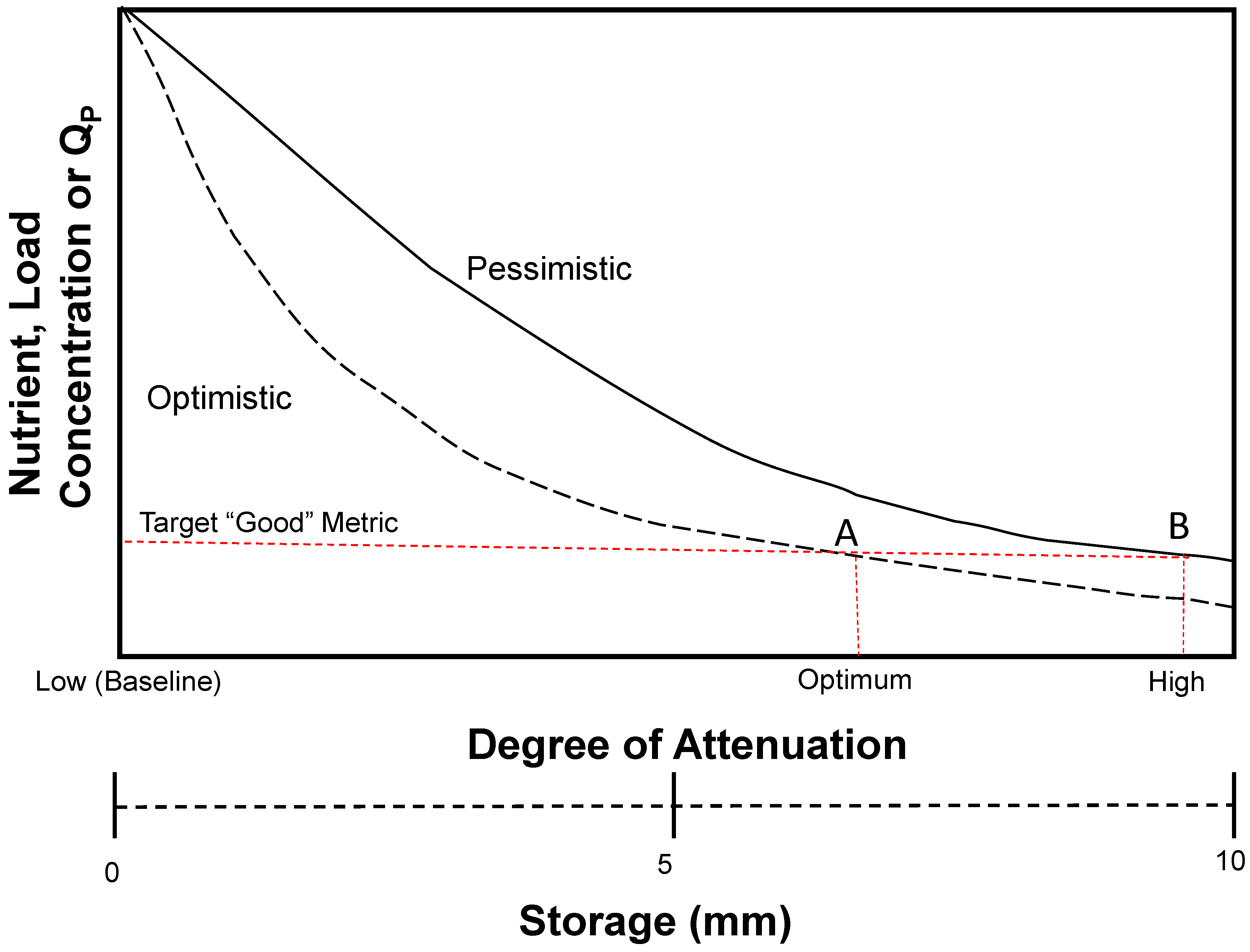
A series of curves, such as those shown in Figure 2 below, can be plotted that relate a representative set of outputs from the modelling (e.g., Qp i.e., peak flow, or the load, or concentration, of TP or SS) to the degree of attenuation or storage in the catchment, where the left axis represents baseline conditions with no additional features present to add storage capacity. Therefore, the origin represents a minimum degree of attenuation and a small amount of storage from the existing floodplain and riparian areas.
Adding features can then be shown to add storage capacity and thus decrease the value of the output(s) until an optimum target is reached. In terms of a conceptual model of adding attenuation storage to a catchment, it may be expedient to consider the UK Water Framework Directive Targets (WFD-UKTAG) [40] for achieving reductions in TRP concentrations in order to improve the ecological status of the catchments (site-specific values were reported by Ockenden [32]). The two curves shown in Figure 2 could represent different types of RAF with a higher or lower optimum design storage capacity that is required to meet the required optima (indicated by the intersections of the curves and the dashed vertical red lines at points A and B). A similar set of curves relating particulate P (PP) load reduction at the catchment outlet to the managed proportion of the catchment for two large catchments in Austria and Hungary were developed [41] using the PhosFate model. The modelled load reductions were achieved by adopting best management practice (BMP) interventions over part of the catchments. In the U.K., a national scale modelling platform based on the export coefficient method simulated several scenarios of nutrient load reductions [36]. The scenarios relevant to the NBC were based on: (i) on-farm mitigation measures, and (ii) farming practices modified to comply with WFD targets. In (i), the TP export from sheep was reduced by 50% and P fertilizer loads applied to grass and arable crops were reduced by 50%, and in (ii), TP loads from cattle farming were reduced by 25% in addition to the reductions in (i). These scenarios predicted that TP exports would reduce by 22.1% and 32.9% respectively (based on data from the year 2000).
The following model simulations investigated whether the target of reducing P and SS concentrations could be met by adding storage capacity. It could be argued that this added storage capacity is actually offsetting the loss of natural attenuation storage caused by deforestation and agricultural intensification. What the final target should be is debatable but the premise that more storage capacity gives a better status is required as part of a long-term plan to reach WFD-UKTAG [40] status, for example. Even as a basic estimate a target of 10 mm of new storage capacity over 1 km2 would require 10,000 m3. This would require a storage pond of 1 m depth with a surface area of 100 m by 100 m. Implementing NBS [1,2] would suggest that this could be spread throughout the catchment in an RAF network, and hopefully soil improvement and buffer zones would add to the storage capacity as well. It is proposed that ditch management is a primary basis for the first two scenarios, hence for 1 m of storage depth, a minimum of 1 km of ditch with an effective width of 10 m would be needed. To gain this storage capacity, a ditch would need to be widened and barriers to flow constructed; Figure 3 is an actual example of how a traditional narrow “V” shaped ditch can be substantially modified (Netherton Burn catchment [11]).

CRAFT Mitigation Modelling

The three mitigation scenarios were modelled using the CRAFT and discussed below. Figure 4 shows sketches indicating both the flow pathways under each scenario (and the baseline) as well as the design of the RAFs themselves (in Scenarios 2 and 3). For simplicity, the area of the mitigated sub-catchment in the modelling was set to 10% of the NBC area (1.25 km2), which was slightly smaller than the actual Mitigation sub-catchment (so this will be referred to as the “mitigated sub-catchment”).
Scenario 1 (Figure 4 top pane): Managing the topsoil in agricultural areas (primarily grassland) to improve the soil health and reduce SS and P loads transported in surface runoff (indicated by the thick blue lines). A review of crop and soil management techniques [42] designed to reduce the quantities of P and SS lost to watercourses found that firstly in upland areas, one of the main mechanisms responsible for P and SS losses is erosion by overland flow detaching soil particles with attached P during rainfall events. Second, in arable fields, the following options can reduce P losses: reduced tillage strategies, application of soil conditioners, crop rotation, crop management, and planting either catch or cover crops. In grasslands, reducing stocking densities and preventing highly trafficked areas from developing (e.g., around feed lots or water troughs) in order to avoid poaching of the soil are the main options available to reduce P losses from the surface runoff. This scenario assumed that the entire mitigated sub-catchment was treated in this way by increasing the maximum infiltration capacity of the soil in the model and evaluated the results in terms of changes to P fluxes. It was assumed that some “pollution swapping” could take place between particulate and soluble forms of P, hence the total P loads may not reduce as much as expected before the “experiment” was carried out. This was essentially a 100% intervention to the land use management across the mitigated sub-catchment. The green lines indicate the major flow pathways under this scenario, which was dominated by infiltration and subsurface flow.
Scenario 2 (Figure 4 middle pane): Treating the mitigated sub-catchment’s watercourses with riparian buffer strips by adding 2000 m3 of additional storage to the sub-catchment and trapping 40% of the SS and attached P transported via surface runoff (overland flow). As a first estimate, it was assumed that up to 10% of the sub-catchment area (i.e., 12.5 ha) was set aside for these measures. This was a 10% land use change intervention option idealising the green/ecological corridor with minimum management other than sediment removal. As the soil was still degraded, overland flow was still dominant during events.
Scenario 3 (Figure 4 lower pane): Adding engineered RAFs to address food flows and to trap and remove 80% of the SS and attached P transported via the surface runoff (overland flow). These features were assumed to be a combination of offline storages and inline ditches that added 8000 m3 of additional storage to the sub-catchment. As a first estimate, it was assumed that 5% of the mitigated sub-catchment area (i.e., 6.25 ha) was set aside and modified for these measures [5]. This was a reduced area, but it required a widening of the ditch to give the increased volume of storage needed to cope with larger storm events. Essentially, the NFM component was being optimised here, and thus a higher level of maintenance may be needed to keep the total infrastructure operating at its optimum.
Scenarios 2 and 3 were modelled as follows: considering that there are two parameters that can be varied in the CRAFT to represent the attenuation and trapping, these are added by the features in the mitigation sub-catchment only, namely (i) KLAG and (ii) a removal or trapping “efficiency” KRE, that apply to the modelled pathways of (a) TP (i.e., PRP and PUP) and (b) SS transported by the surface runoff pathway. Their values were pre-selected for Scenarios 2 and 3 (see Table 2) based on expert judgement and evidence from the field experiments conducted in the mitigation sub-catchment.
The parameter values used for the baseline were:
  • KLAG = 0.75 h−1 (representing natural attenuation, from the “lagged” simulation [28].
  • KRE = 0 (for the baseline with no trapping).
The unmitigated portion of the catchment was modelled with CRAFT using the calibrated baseline parameter set [28]. There was no additional attenuation of flow, sediments, and nutrients, or removal simulated in this portion of the catchment, or in the fast subsurface and deep groundwater flow pathways in any of the scenarios anywhere.
In the CRAFT, nutrients (in this case PUP and PRP fluxes) and SS were modelled slightly differently from runoff in that their removal was permitted from the attenuation store, which represents the ability of the modelled features to remove (i.e., trap) particulates. Therefore, the mass balance Equations (1) to (3) for the stores become (for the components of PRP, PUP and SS transported by the surface runoff (SR) pathway, which is indicated by “SR” in parentheses):
PRPL(SR)out = PRPL(SR)in (1 − KLAG)(1 − KRE)
PUPL(SR)out = PUPL(SR)in (1 − KLAG)(1 − KRE)
SSL(SR)out = SSL(SR)in (1 − KLAG)(1 − KRE)
where PRPLout, PUPLout, and SSLout were the loads per time step of PRP, PUP, and SS from the mitigated sub-catchments, respectively. CRAFT outputs were the specific discharge (i.e., runoff depth) and specific yield (i.e., load/unit area). Therefore, the model outputs were scaled up by the areas of the mitigated (Amit) and unmitigated areas of the catchments (Aumit) to obtain the total flow and loads from the entire catchment. SRP loads from the fast subsurface and slow groundwater flow components were added to the loads from the surface runoff pathways in a mass balance to compute a total TP load. Concentrations of TP and SS at the catchment’s or sub-catchment’s outlet were calculated by dividing the total loads by the total flow. The flow from the catchment Qcatch was the sum of the flow components from both the mitigated and unmitigated areas, where the suffixes “mit” and “umit” denote these respectively
Qcatch = Qmit + Qumit
Nutrient (TP) and SS concentrations were calculated in the same way, where TPL, TRPL, and SSL were the loads with suffixes (as above) indicating which part of the catchment (suffix “catch”) the load originated from
TPLcatch = TPLmit + TPLumit
where
TPL = PUPL(SR) + TRPL
SSLcatch = SSLmit + SSLumit
A simplified, additive mixing model was used to calculate the flows and loads at the outlet, with no additional attenuation added to represent the in-stream reaches (clearly this was a simplification of reality where in-stream routing could further attenuate the outlet hydrograph [43]). This assumption holds for small catchments where the main stem channel length is less than 10 km and the travel time (lag) between hillslope and outlet is of the order of a few hours. The functional unit defined by a CRAFT sub-catchment could equate to a representative elementary area (REA) [44].
Lastly, the maximum volumes of added storage (Vadd) required in the mitigated sub-catchment were supplied by the user for each scenario. The area (Amit) of the mitigated sub-catchment is set to 10% of the total catchment area (At). The model calculated the depth in the attenuation store at each timestep (Dadd), as it works with depths rather than volumes. The attenuation store was empty at the start of the simulation. The maximum storage volume required in the attenuation store Vatt could therefore be calculated using Equations (8)–(10).
Amit = 0.1At
Vatt = Vnat + Vadd
where, in general terms, at each timestep t:
V(t) = Amit D(t)
Thus, the required model parameter, Dmax was calculated using Equation (11):
Dmax = Vatt/Amit
where Dmax was the maximum depth of water in the attenuation store (m), Vnat was the modelled volume of natural storage in the catchment, which comes from the results of calibrated baseline model results (by extracting Dmax from these).
Since the outflow Qmit from the attenuation store was a function of KLAG, the required value of this parameter could be back-calculated from Equation (12). In practice this was obtained by increasing the value of the parameter until the desired value of Dmax was achieved in the attenuation store.
Qmit = Vatt(1 − KLAG)
The results from these simulations provided the flows and loads of TP and SS from the mitigated sub-catchment (i.e., Qmit, TPLmit and SSLmit in Equations (4)–(7)).

3. Results

The CRAFT had already been calibrated to baseline conditions during October 2011–September 2012 in the NBC [28]. In this study the parameter values from the “lagged” scenario, where natural attenuation were included, were used for the baseline simulation. The modelled runoff is shown in Figure 5 for comparison against the observed runoff, for the period January 1 to September 30, 2012 at the NBC outlet. Table 1 summarizes the observations recorded during the entire period between April and September 2012 including the three selected events. The SS yield of 18 t km−2 over a six-month period appears to fit into the middle range of estimates for the larger Eden catchment made at 14 monitoring points, which was 4–73 t km−2 year [34]. The lowest monitoring point measured yield from a 1373 km2 sub-catchment of the River Eden [34].

3.1. Results from the 2012 Events (Baseline Simulation)

In terms of investigating the temporal scaling of the results, three large events during a wet 5-month period in 2012 were analysed, and these are denoted by the numbered boxes in Figure 5. According to the observations, the annual (2011–2012) exports of TP and SS from the NBC were 1762 kg and 477.5 tonnes respectively [28,32], and from the three events during 2012, the modelled TP load was predicted to be 725 kg and the modelled SS load was 322 tonnes from the baseline simulation, which indicates that these three events alone contributed a significant proportion of the annual P and sediment exports.

3.2. Results from Scenarios 1–3

Table 2 shows the model parameter values used in each of the scenarios along with the values used in the baseline simulation (for comparison). It also shows the total and added storage in the attenuation component of the model in Scenarios 1–3.
The left-hand pane of Figure 6 shows the modelled and observed runoff at the NBC outlet for Event 3. The modelled attenuation storage per unit time and area (expressed as a depth) is also shown by the solid black line, and both modelled runoff and storage are shown for the baseline case only. The right-hand pane of Figure 6 shows the modelled runoff from the mitigated sub-catchment for the (unmitigated) baseline (solid red line) and Scenarios 2 and 3 (dotted and dashed red lines). The black lines show the attenuation storage during the event for the three simulations (same line styles as runoff). Its value is shown on the right-hand axis and Scenario 3 had a far greater effect on the shape of the hydrograph than Scenario 2 due to the much greater additional added storage (8000 m3 vs. 2000 m3, which is the equivalent of storing an additional 6.4 mm vs. 1.6 mm of runoff during events in the attenuation store). The effect was to both flatten and delay the hydrograph peak due to added attenuation. Both runoff and storage in Scenario 1 were identical to the baseline values as no attenuation storage was added to the model in this scenario, so these are not shown for clarity.
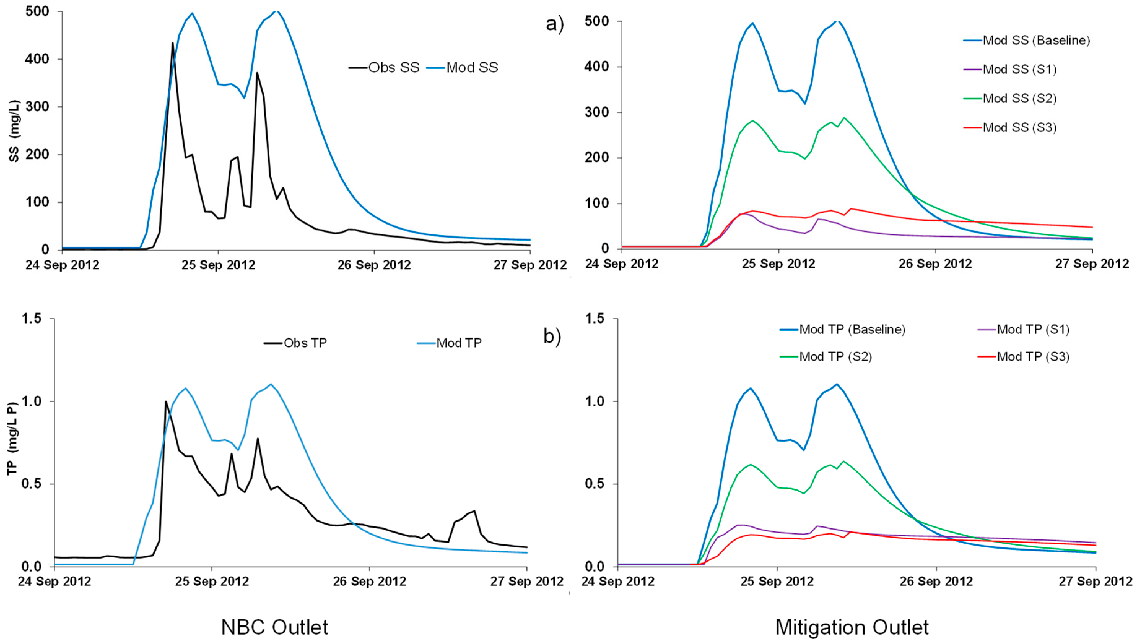
Figure 7 shows the results from Scenarios 1–3 alongside the baseline (blue) results for the SS (Figure 7a) and TP (Figure 7b) concentrations in event 3. These were extracted at the NBC outlet (left hand panes) and mitigated sub-catchment outlet (right hand panes) and are shown as different coloured lines for each scenario. The effect on TP concentrations during event 3 can be seen in Figure 7b. The two scenarios that added attenuation storage and trapped particulate P (PUP) (Scenario 2 (green) and Scenario 3 (red)) reduced the peak TP concentrations, but Scenario 1 actually increased the TP concentrations during the falling limb event due to an increase in SRP in the fast subsurface flow pathway; however, the maximum TP concentration was reduced by eliminating the surface runoff pathway as a major source of PUP through improved soil management. Hence, the overall outcome for the event was better even though some instantaneous values worsened. Scenarios 1 (purple) and 3 (red) had the greatest effect on TP concentrations during event 3 in terms of reducing them; in the case of Scenarios 2 and 3, this was due to reducing the amount of PUP exported from the mitigated sub-catchment through trapping sediment with attached P.
In the left-hand panes of Figure 7a,b, the black lines represent observed concentrations and the blue lines represent the modelled concentrations (at the NBC outlet) from the baseline simulation. The model performed reasonably well in capturing the peak concentrations, although there are some errors in timing of the peaks (compared with the blue line). The model underpredicted the TP concentrations slightly.
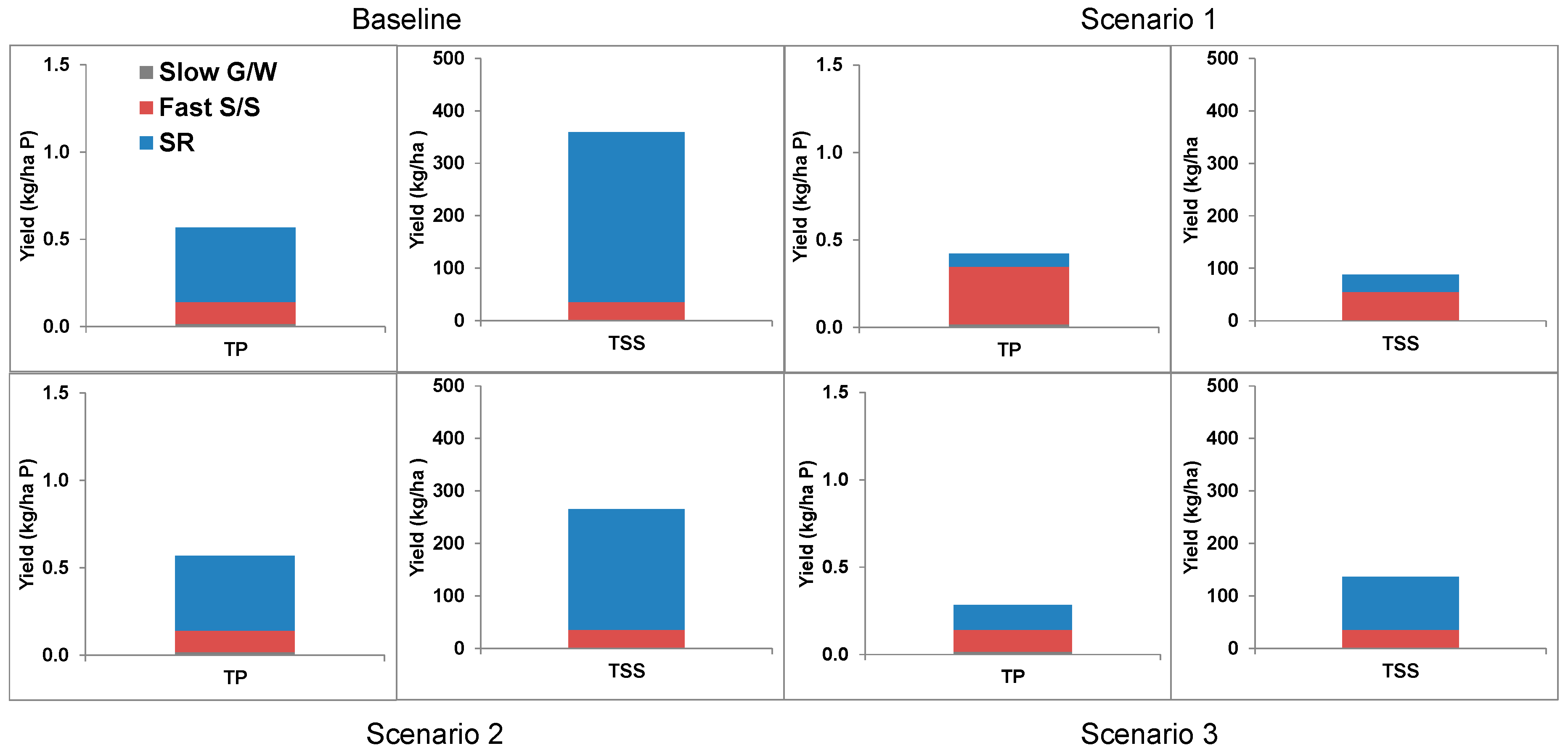
In terms of P yields, Figure 8 shows the modelled yields of TP and SS from the baseline simulation alongside the yields from Scenarios 1–3 from the mitigated sub-catchment. The bars are split into three coloured segments, each representing the yield transported by each of the three flow pathways (SR = surface runoff, “Fast S/S” = fast subsurface, “Slow G/W” = slow groundwater). The sum of the three segments was thus the total yield from all three pathways added together. The results covered a six-month period in 2012. Therefore, these yields included periods of low flows in addition to events; however, based on field observations and the fluxes transported by the modelled flow pathways, surface runoff during events contributed to the vast majority of the total SS and P losses from this catchment.
In Scenario 1, the total yield of SS and TP reduced quite drastically due to the reduction in transport via the fast surface flow pathway. There was some pollution swapping into SRP (transported by the fast subsurface flow pathway) as a result of these interventions increasing the amount of P that could infiltrate through the upper soil layer.
The results from Scenarios 2 and 3, where there has been simulation of the removal of SS and P from the surface runoff pathway by mitigation RAFs, show that there was a considerable reduction in SS TP yields according to the model. This reduction was achieved by trapping SS and attached particulate P, hence also reducing the components of PUP and PRP transported by the surface runoff pathway by 40–80%. These results were for the mitigated sub-catchment (1.25 km2) only and the results scaled up to the NBC outlet are discussed below.

3.3. Comparison of Recent Sampling Campaign and Model Results

The most recent available results from the mitigation features were as follows [24]. The mass of TP and SS trapped by the five features ranged from 1.5 to 2.5 kg and 0.5 to 2.8 tonnes, respectively (total mass 9.8 kg of P and 6.5 tonnes of sediment). These totals represent the masses of TP and SS collected over a 9-month period ending in summer 2015. Expressed as a yield of TP (loads per unit area over the Mitigation sub-catchment), the reductions were 0.06 kg·ha−1 of TP and 0.04 t·ha−1 of SS. At present, only 24% of the sub-catchment area is treated by these features (3% of the NBC).
Model simulations using the parameter combination that was described above in the NBC over a 6-month period in 2012 that included the three events in April–September estimated that the fluxes of P trapped by mitigation features would be 0.23 kg·ha−1 of PUP and 0.06 kg·ha−1 of PRP in Scenario 2, and 0.46 kg·ha−1 of PUP and 0.11 kg·ha−1 of PRP in Scenario 3. The ratio between these yields corresponds closely to the ratios between the values of the parameter KRE in Scenarios 2 and 3 (40% and 80%, respectively).

4. Discussion

It is important to remember that European agricultural catchments have been heavily modified by centuries of intensive farming practices such that the degree of attenuation and storage have been reduced from prehistoric times when the catchments were in pristine (forested) condition prior to anthropogenic modification.
One pertinent research question relates to the detectability of mitigation features at the catchment scale, which in this case was ten times larger than the sub-catchment where the features were located. The results in terms of reducing the mean and maximum concentrations of SS and TP during Event 3 were analysed and were shown in the upper pane of Figure 9 for the three scenarios. Note that the effects of adding the features on the modelled Qp at the NBC outlet were not evaluated for reasons given above.
Scenario 1 evaluated the soil management improvements covering 10% of the total catchment to reduce surface runoff and particulate P loads transported by this pathway. The event mean and maximum TP concentrations were reduced by 4.7% and 6.4%, respectively, due to reductions in the PUP concentrations transported by the surface runoff pathway. The reductions in the event maximum TP concentrations were 4.3–5.9% during Event 3 at the NBC outlet when both attenuation storage and the removal of P were simulated in Scenarios 2 and 3. The reductions in Events 1 and 2 were similar under the three scenarios to Event 3 and are shown in the lower pane of Figure 9 for Scenario 3 only. These reductions are likely to be conservative estimates since the effect of the in-stream routing and dispersion along the channel reach that connected the mitigated sub-catchment outlet to the main channel outlet were not incorporated into the model structure.
In Scenario 1, there is considerable scope however for reducing the maximum TP concentration and TP yields by this method, as shown by the reduction in the maximum TP concentration in Event 1 of over 6% (Figure 9). In Scenario 2, the value of KRE of 40% was quite conservative compared to some of the recent findings from U.K. field studies [11,12,24,45], but the load reduction was still predicted to be up to 4% at the catchment outlet with a smaller predicted decrease in the mean and maximum event TP concentration (less than those decreases achieved by Scenarios 1 (TP) and 3 (TP)). The model results showed that adding additional attenuation and removing P from 10% of the catchment reduced event loads of TP by up to 8% at the outlet under Scenario 3 (where KRE was 80%), which was the best performing of the three scenarios.
In terms of locating mitigation features of size ca. 2000–8000 m3 in one of the headwater sub-catchments of the NBC, the volumes required in Scenarios 2 and 3 do not seem excessively large if one assumes that a maximum water depth of 1 m is permissible under the relevant legislation (thus requiring 0.2 and 0.8 ha of the catchments, respectively, to be set aside for storage). In the U.K., stringent government guidelines [21] apply to all features greater than 10,000 m3 capacity, which may make constructing larger features expensive and probably uneconomic in terms of a cost–benefit ratio. For comparison, the five recent pilot features constructed in the NBC Mitigation sub-catchment had a total storage capacity of circa 400 m3 and treated only 38.4 ha (less than 0.031% of the total NBC catchment by area). It is important to consider that RAFs should be constructed in other parts of the NBC in order to achieve the desired reduction in P concentrations and loads.
It should be stressed that further research is required to evaluate the performance of these mitigation features when constructed at a larger scale than previously, i.e., up to 4–8 times greater than at the scale (17–34 ha) of Belford Burn [11,12,45] and up to 3 times greater than the 38 ha of the NBC Mitigation sub-catchment [24]. It is vital that trapped material is recovered by removal of sediment in well-designed traps or by removing vegetation.
Field studies are required to ascertain whether Scenario 1 could deliver the results shown here in reality; however, subsurface field drains are known to be a source of high SRP loads from agricultural catchments. Under Scenario 2, the strategic location of ditches and small channels in the landscape may play a crucial role in future management option for surface runoff driven agricultural pollution. The space in and around ditches afforded by buffer zones and fenced off channels could allow the construction of long riparian mitigation zones without significant impact on farming. The ability to address both NFM and pollution targets and create new ecological habitats may justify the investment and maintenance of RAFs [6]. The implication from all three scenarios is that an extensive network of RAFs is needed in farmed landscapes, and this could require a considerable shift in standard farming and environmental payments for schemes to be taken up and maintenance to be ensured. In reality, a mixture of all three scenarios being delivered would be attractive and that will very much depend on the local conditions and the farming community.
It is possible that unforeseen constraints, such as planning regulations, infrastructure restrictions and land ownership issues, may further restrict the widespread adoption of mitigation measures [4,22]. Therefore, the exact location of these flow pathways and identification of suitable sites for constructing features is beyond the scope of this study.
Further reductions in loads could be achieved in any case by targeting a larger percentage of the catchment for the construction of mitigation features, which in rural, pastoral farming-based areas like Cumbria (where the EdenDTC project is based) may be achievable, especially on a seasonal basis under the right conditions and government policies to compensate farmers. However, this policy might not be so attractive if the catchment contains arable land of higher value to the farmers than the rough and improved pasture in the upper Eden [22].

5. Conclusions

An attenuation component has been added to the CRAFT model to represent the storage and attenuation of surface runoff during events and also the trapping of particulate forms of P and suspended sediment, which provides a methodology for modelling NBS.
Currently, the removal efficiency of the trapping process has to be supplied by the user based on expert knowledge. The effect of adding attenuation and trapping SS plus particulate forms of P has been modelled in a small (1.25 km2) sub-catchment. Due to the variability in the removal efficiencies measured in the field from previous studies of NBS, two modelling scenarios with removal efficiencies of 40% and 80% have been evaluated here with the latter clearly providing the best results in terms of improvements in reducing sediment and nutrient (P) fluxes and concentrations.
According to the model results, at the outlet of the entire Newby Beck catchment (ca. 10× larger), a small reduction in the peak SS and TP concentrations would be observable during an event where surface runoff is the dominant pathway. A third scenario evaluated the impacts of reducing surface runoff to represent improved land management. This scenario reduced the amount of SS and P transported by the surface runoff pathway but increased the amount of SRP transported by the fast subsurface flow pathway. The reduction in both SS fluxes and maximum event concentration was more pronounced since the majority of the modelled flux was predicted to occur via the surface runoff pathway.
This modelling study represents a first step towards developing and testing a fully integrated model that can simulate both natural and added attenuation storage. Mitigation features are represented in the model as an aggregated storage effect rather than through utilizing a physically-based model of each feature individually. Research into the implications of adding new attenuation features to catchments with lighter soils and groundwater dominated runoff as well as adoption and maintenance issues is also needed.
One final conclusion arising from this study is the need to provide guidance to end users. The hypothetical attenuation versus mitigation curve can inform a policymaker on how to set annual targets over time that dictates the total amount of attenuation added to a catchment over a longer period. Hence, these guidelines would indicate how long it would take to reach the environmental target(s) based on an annual financial budget.

Author Contributions

Conceptualization, R.A. and P.Q.; Data curation, N.B.; Formal analysis, R.A.; Investigation, R.A.; Methodology, R.A., P.Q., and N.B.; Software, R.A.; Writing—original draft, R.A.; Writing—review and editing, R.A., P.Q., N.B., and S.R.

Funding

The Eden Demonstration Test Catchment (Eden DTC) research platform that funded this research and supplied the monitoring data used in this paper is funded by the Department for Environment, Food and Rural Affairs (DEFRA) (project WQ0210) and is further supported by the Welsh Assembly Government and the Environment Agency.

Acknowledgments

The Eden DTC (www.edendtc.org.uk) team includes research staff from Lancaster University, University of Durham, Newcastle University (PROACTIVE team), Eden Rivers Trust, Centre for Ecology and Hydrology, British Geological Survey, and Newton Rigg College, and their assistance in undertaking this research is gratefully acknowledged.

Conflicts of Interest

The authors declare no conflict of interest.

References

  1. NWRM—Natural Water Retention Measures. European Union. Available online: www.nwrm.eu (accessed on 9 February 2018).
  2. Environment Agency Working with Natural Processes to Reduce Flood Risk. Available online: www.gov.uk/government/publications/working-with-natural-processes-to-reduce-flood-risk Published 31/10/2017 (accessed on 9 February 2018).
  3. O’Connell, P.E.; Ewen, J.; O’Donnell, G.; Quinn, P. Is there a link between agricultural land-use management and flooding? Hydrol. Earth Syst. Sci. 2007, 11, 96–107. [Google Scholar] [CrossRef]
  4. Nisbet, T.R.; Marrington, S.; Thomas, H.; Broadmeadow, S.B.; Valatin, G. Slowing the Flow at Pickering. Final Report for the Department of Environment, Food and Rural Affairs; Project RMP5455; DEFRA: London, UK, 2011. [Google Scholar]
  5. Quinn, P.; O’Donnell, G.; Nicholson, A.; Wilkinson, M.; Owen, G.; Jonczyk, J.; Barber, N.; Hardwick, M.; Davies, G. Potential Use of Runoff Attenuation Features in Small Rural Catchments for Flood Mitigation; Newcastle University, Environment Agency, Royal Haskoning DHV: Newcastle Upon Tyne, UK, 2013. [Google Scholar]
  6. Charlesworth, S.M.; Booth, C.A. Sustainable Surface Water Management: A Handbook for SUDS; John Wiley & Sons: Chichester, UK, 2016. [Google Scholar]
  7. SEPA. Natural Flood Management Handbook, 2nd ed.; Scottish Environment Protection Agency: Stirling, UK, 2015; Available online: https://www.sepa.org.uk/media/163560/sepa-natural-flood-management-handbook1.pdf (accessed on 9 February 2018).
  8. Duffy, A.; Moir, S.; Berwick, N.; Shabashow, J.; D’Arcy, B.; Wade, R. Rural Sustainable Drainage Systems: A Practical Design and Build. Guide for Scotland’s Farmers and Landowner; CREW: Scotland, UK, 2015; Available online: http://crew.ac.uk/publications (accessed on 6 June 2018).
  9. Wilkinson, M.E.; Quinn, P.F.; Welton, P. Runoff management during the September 2008 floods in the Belford catchment, Northumberland. J. Flood Risk Manag. 2010, 3, 285–295. [Google Scholar] [CrossRef]
  10. Nisbet, T.R.; Thomas, H. Restoring Floodplain Woodland for Flood Alleviation. Final Report for the Department of Environment, Food and Rural Affairs; Project SLD2316; DEFRA: London, UK, 2008. [Google Scholar]
  11. Barber, N. Sediment, Nutrient and Runoff Management and Mitigation in Rural Catchments. Ph.D. Thesis, Newcastle University, Newcastle Upon Tyne, UK, 2014. [Google Scholar]
  12. Barber, N.J.; Quinn, P.F. Mitigating diffuse water pollution from agriculture using soft engineered runoff attenuation features. Area 2012, 44, 454–462. [Google Scholar] [CrossRef]
  13. Deasy, C.; Quinton, J.N.; Silgram, M.; Bailey, A.P.; Jackson, B.; Stevens, C.J. Contributing understanding of mitigation options for phosphorus and sediment to a review of the efficacy of contemporary agricultural stewardship measures. Agric. Syst. 2010, 103, 105–109. [Google Scholar] [CrossRef] [Green Version]
  14. Doody, D.G.; Archbold, M.; Foy, R.H.; Flynn, R. Approaches to the implementation of the Water Framework Directive: Targeting mitigation measures at critical source areas of diffuse phosphorus in Irish catchments. J. Environ. Manag. 2012, 93, 225–234. [Google Scholar] [CrossRef] [PubMed]
  15. Wilcock, R.J.; Müller, K.; van Assema, G.B.; Bellingham, M.A.; Ovenden, R. Attenuation of nitrogen, phosphorus and E. coli inputs from pasture runoff to surface waters by a farm wetland: The importance of wetland shape and residence time. Water Air Soil Pollut. 2012, 223, 499–509. [Google Scholar] [CrossRef]
  16. Avery, L.M. Rural Sustainable Drainage Systems (RSuDS); Environment Agency: Bristol, UK, 2012. [Google Scholar]
  17. Blöschl, G. Scaling in hydrology. Hydrol. Process. 2001, 15, 709–711. [Google Scholar] [CrossRef]
  18. Biggs, J.; Stoate, C.; Williams, P.; Brown, C.; Casey, A.; Davies, S.; Diego, I.G.; Hawczak, A.; Kizuka, T.; McGoff, E.; et al. Water Friendly Farming Autumn 2016 Update; Freshwater Habitats Trust: Oxford, UK; Game & Wildlife Conservation Trust: Fordingbridge, UK, 2016; Available online: https://freshwaterhabitats.org.uk/wp-content/uploads/2016/11/Water-Friendly-Farming-update-2016.pdf (accessed on 18 April 2018).
  19. Fealy, R.M.; Buckley, C.; Mechan, S.; Melland, A.; Mellander, P.E.; Shortle, G.; Wall, D.; Jordan, P. The Irish Agricultural Catchments Programme: Catchment selection using spatial multi-criteria decision analysis. Soil Use Manag. 2010, 26, 225–236. [Google Scholar] [CrossRef]
  20. Owen, G.J.; Perks, M.T.; Benskin, C.M.H.; Wilkinson, M.E.; Jonczyk, J.; Quinn, P.F. Monitoring agricultural diffuse pollution through a dense monitoring network in the River Eden Demonstration Test Catchment, Cumbria, UK. Area 2012, 44, 443–453. [Google Scholar] [CrossRef]
  21. McGonigle, D.F.; Burke, S.P.; Collins, A.L.; Gartner, R.; Haft, M.R.; Harris, R.C.; Haygarth, P.M.; Hedges, M.C.; Hiscock, K.M.; Lovett, A.A. Developing demonstration test catchments as a platform for transdisciplinary land management research in England and Wales. Environ. Sci. Process. Impacts 2014, 16, 1618–1628. [Google Scholar] [CrossRef] [PubMed]
  22. Metcalfe, P.; Beven, K.; Hankin, B.; Lamb, R. A modelling framework for evaluation of the hydrological impacts of nature-based approaches to flood risk management, with application to in-channel interventions across a 29 km2 scale catchment in the United Kingdom. Hydrol. Process. 2017, 31, 1734–1748. [Google Scholar] [CrossRef]
  23. Bechmann, M.; Deelstra, J.; Stålnacke, P.; Eggestad, H.O.; Øygarden, L.; Pengerud, A. Monitoring catchment scale agricultural pollution in Norway: Policy instruments, implementation of mitigation methods and trends in nutrient and sediment losses. Environ. Sci. Policy 2008, 11, 102–114. [Google Scholar] [CrossRef]
  24. Barber, N.J.; Reaney, S.N.; Barker, P.A.; Benskin, C.; Burke, S.; Cleasby, W.; Haygarth, P.; Jonczyk, J.C.; Owen, G.J.; Snell, M.A.; et al. The treatment train approach to reducing non­point source pollution from agriculture. In Proceedings of the AGU Fall Meeting, San Francisco, CA, USA, 12–16 December 2016. [Google Scholar]
  25. Kay, P.; Edwards, A.C.; Foulger, M. A review of the efficacy of contemporary agricultural stewardship measures for ameliorating water pollution problems of key concern to the UK water industry. Agric. Syst. 2009, 99, 67–75. [Google Scholar] [CrossRef] [Green Version]
  26. Ensign, S.H.; McMillan, S.K.; Thompson, S.P.; Piehler, M.F. Nitrogen and phosphorus attenuation within the stream network of a coastal, agricultural watershed. J. Environ. Qual. 2006, 35, 1237–1247. [Google Scholar] [CrossRef] [PubMed]
  27. Adams, R.; Quinn, P.F.; Bowes, M.J. The Catchment Runoff Attenuation Flux Tool, A minimum information requirement nutrient pollution model. Hydrol. Earth Syst. Sci. 2015, 19, 1641–1657. [Google Scholar] [CrossRef]
  28. Adams, R.; Quinn, P.F.; Perks, M.; Barber, N.J.; Jonczyk, J.; Owen, G.J. Simulating high frequency water quality monitoring data using a catchment runoff attenuation flux tool (CRAFT). Sci. Total Environ. 2016, 572, 1622–1635. [Google Scholar] [CrossRef] [PubMed]
  29. Heathwaite, A.L.; Quinn, P.F.; Hewett, C.J.M. Modelling and managing critical source areas of diffuse pollution from agricultural land using flow connectivity simulation. J. Hydrol. 2005, 304, 446–461. [Google Scholar] [CrossRef]
  30. Singh, V.P. Is Hydrology kinematic? Hydrol. Process. 2002, 16, 667–716. [Google Scholar] [CrossRef]
  31. Perks, M.T.; Owen, G.J.; Benskin, C.M.H.; Jonczyk, J.; Deasy, C.; Burke, S.; Haygarth, P.M. Dominant mechanisms for the delivery of fine sediment and phosphorus to fluvial networks draining grassland dominated headwater catchments. Sci. Total Environ. 2015, 523, 178–190. [Google Scholar] [CrossRef] [PubMed] [Green Version]
  32. Ockenden, M.C.; Deasy, C.E.; Benskin, C.M.; Beven, K.J.; Burke, S.; Collins, A.L.; Evans, R.; Falloon, P.D.; Forber, K.J.; Hiscock, K.M.; et al. Potential effects of changing climate on catchment processes and nutrient transfers: Evidence from high temporal concentration-flow dynamics in headwater catchments. Sci. Total Environ. 2016, 548, 325–339. [Google Scholar] [CrossRef] [PubMed] [Green Version]
  33. Ockenden, M.C.; Tych, W.; Beven, K.; Collins, A.; Evans, R.; Falloon, P.; Forber, K.; Hiscock, K.; Hollaway, M.; Kahana, R.; et al. Prediction of storm transfers and annual loads with data-based mechanistic models using high-frequency data. Hydrol. Earth Syst. Sci. 2017, 18, 6425–6444. [Google Scholar] [CrossRef]
  34. Mills, C.F.; Bathurst, J.C. Spatial variability of suspended sediment yield in a gravel-bed river across four orders of magnitude of catchment area. Catena 2015, 133, 14–24. [Google Scholar] [CrossRef]
  35. European Commission. Directive 2000/60/EC: Establishing a Framework for Community Action in the Field of Water Policy. (The Water Framework Directive); European Commission: Brussels, Belgium, 2000. [Google Scholar]
  36. Greene, S.; Johnes, P.J.; Bloomfield, J.P.; Reaney, S.M.; Lawley, R.; Elkhatib, Y.; Freer, J.; Odoni, N.; Macleod, C.J.; Percy, B. A geospatial framework to support integrated biogeochemical modelling in the United Kingdom. Environ. Model. Softw. 2015, 68, 219–232. [Google Scholar] [CrossRef] [Green Version]
  37. Hewett, C.J.; Quinn, P.F.; Heathwaite, A.L.; Doyle, A.; Burke, S.; Whitehead, P.G.; Lerner, D.N. A multi-scale framework for strategic management of diffuse pollution. Environ. Model. Softw. 2009, 24, 74–85. [Google Scholar] [CrossRef]
  38. Lane, S.N.; Reaney, S.M.; Heathwaite, A.L. Representation of landscape hydrological connectivity using a topographically driven surface flow index. Water Resour. Res. 2009, 45. [Google Scholar] [CrossRef] [Green Version]
  39. Reaney, S.M.; Lane, S.N.; Heathwaite, A.L.; Dugdale, L.J. Risk-based modelling of diffuse land use impacts from rural landscapes upon salmonid fry abundance. Ecol. Model. 2011, 222, 1016–1029. [Google Scholar] [CrossRef] [Green Version]
  40. WFD-UKTAG. UKTAG River Assessment Method—Phosphorus: River Phosphorus Standards; Water Framework Directive-United Kingdom Technical Advisory Group (WFD-UKTAG): Stirling, UK, 2014. [Google Scholar]
  41. Kovacs, A.; Honti, M.; Zessner, M.; Eder, A.; Clement, A.; Blöschl, G. Identification of phosphorus emission hotspots in agricultural catchments. Sci. Total Environ. 2012, 433, 74–88. [Google Scholar] [CrossRef] [PubMed]
  42. Schoumans, O.F.; Chardon, W.J.; Bechmann, M.E.; Gascuel-Odoux, C.; Hofman, G.; Kronvang, B.; Dorioz, J.M. Mitigation options to reduce phosphorus losses from the agricultural sector and improve surface water quality: A review. Sci. Total Environ. 2014, 468, 1255–1266. [Google Scholar] [CrossRef] [PubMed]
  43. Beven, K. On the generalized kinematic routing method. Water Resour. Res. 1979, 15, 1238–1242. [Google Scholar] [CrossRef]
  44. Wood, E.F.; Sivapalan, M.; Beven, K.; Band, L. Effects of spatial variability and scale with implications to hydrologic modeling. J. Hydrol. 1988, 102, 29–47. [Google Scholar] [CrossRef]
  45. Wilkinson, M.E.; Quinn, P.F.; Barber, N.J.; Jonczyk, J. A framework for managing runoff and pollution in the rural landscape using a Catchment Systems Engineering approach. Sci. Total Environ. 2014, 468, 1245–1254. [Google Scholar] [CrossRef] [PubMed]
Figure 1. Map of the Eden catchment showing the NBC sub-catchment studied as part of the EdenDTC project, and the location of the monitoring sites for rainfall and flow in the sub-catchments. Contours at 20 m intervals depict the topography.
Water 10 01227 g001
Figure 2. Sketch of relationship between load or concentration and degree of attenuation and storage (both plotted on the x-axis) in a hypothetical catchment indicating how adding storage can achieve a desired target.
Water 10 01227 g002
Figure 3. An example of a modified ditch with flow barriers acting as both a sediment trap and flood flow storage in Netherton Burn (photo from Barber 2013, credit to N. Barber).
Water 10 01227 g003
Figure 4. Schematic describing Runoff Pathways and design sketches of RAFs in Scenarios 1–3, and Runoff Pathways in the Baseline simulation. Note that Scenario 3 has a widened ditch eating into the buffer zone.
Water 10 01227 g004
Figure 5. Time series plots of observed (“Obs”) and modelled (“Mod”) (baseline) runoff plus rainfall at the NBC outlet from January–September 2012.
Water 10 01227 g005
Figure 6. Time series plots of runoff (Q) and storage (S) during Event 3: Left hand (LH) pane shows modelled and observed Q (red) and modelled S (black) for baseline only at the NBC outlet. Right hand (RH) pane shows modelled Q (red) and S (black) at the mitigated sub-catchment outlet with different line types representing the baseline and Scenarios 2 (S2) and 3 (S3).
Water 10 01227 g006
Figure 7. (a) LH pane shows the modelled (“Mod”) and observed (“Obs”) SS concentrations at the NBC outlet. RH pane shows the SS concentrations at the mitigated sub-catchment outlet (Scenarios 1–3 shown by colored lines, with baseline in blue). (b) LH pane shows modelled (black) and observed (blue) TP concentrations at the NBC outlet. RH pane shows the TP concentrations at the mitigated sub-catchment outlet (Scenarios 1–3 shown by colored lines, with baseline in blue). Only Event 3 is shown.
Water 10 01227 g007
Figure 8. Plots showing modelled yields of TP and SS exported from the mitigated sub-catchment under all three scenarios in comparison with the modelled yields from the baseline.
Water 10 01227 g008
Figure 9. Plots showing the percentage reductions in TP and SS concentrations modelled at the NBC outlet achieved under: LH pane shows the three scenarios (legend indicates the scenario number) relative to the baseline in Event 3 only, and the RH pane shows the improvements under Scenario 3 relative to the baseline only, with Events 1–3 shown for comparison (improvements in Events 1–3 shown with different fill patterns).
Water 10 01227 g009
Table 1. Observations at the NBC April–September 2012 from monitoring data.
ObservationValue
Catchment Area (km2)12.5
Rainfall (mm)686
Runoff (mm)303
TP Yield (kg·ha−1)0.73
SS Yield (t·km−2)18.1
TP Load (kg)908
SS Load (t)229
TP mean Concentration (mg P·L−1)0.077
SS mean Concentration (mg·L−1)4.3
Table 2. Details of the scenarios modelled in the NBC: parameter Values and storages (S). Baseline values are shown for comparison.
ScenarioKLAG
(h−1)
S (Total)
(mm)
S (Total)
(m3)
S (Added)
(m3)
KRE (-)Other
Parameters
Baseline0.754.86607500No changes
10.754.86607500Increased
Infiltration
Capacity
20.836.46807520000.4No changes
30.9311.314,07580000.8No changes