Article

A Novel, Coupled CFD-DEM Model for the Flow Characteristics of Particles Inside a Pipe

1
School of Engineering and Technology, China University of Geosciences (Beijing), Beijing 100083, China
2
Guangzhou Urban Planning & Design Survey Research Institute, Guangzhou 510000, China
*
Author to whom correspondence should be addressed.
Water 2019, 11(11), 2381; https://doi.org/10.3390/w11112381
Submission received: 22 October 2019 / Revised: 9 November 2019 / Accepted: 11 November 2019 / Published: 14 November 2019
(This article belongs to the Special Issue Hydraulic Dynamic Calculation and Simulation)

Abstract

:
This study developed a novel, 3D coupled computational fluid dynamics (CFD)-discrete element method (DEM) model by coupling two software programs, OpenFOAM and PFC3D, to solve problems related to fluid–particle interaction systems. The complete governing equations and the flow chart of the coupling calculations are clearly presented herein. The coupled CFD-DEM model was first benchmarked using two classic geo-mechanics problems, for which the analytical solutions are available. Then, the CFD-DEM model was employed to investigate the flow characteristics of a particle heap subjected to the effects of water inside a pipe under different conditions. The results showed that particle size and pipe inclination angle can significantly affect the particle flow morphology, total kinetic energy and erosion rate for mono-sized particles, whereas polydisperse particles had a slight effect. This model can accurately describe the flow characteristics of particles inside a pipe, and the results of this study were consistent with those of previous studies. The reliability of this model was further demonstrated, which showed that this model can provide valuable references for solving similar problems such as soil erosion and bridge scour problems.

1. Introduction

The flow of particles inside a pipe is one of the most typical fluid–particle interaction systems and is ubiquitous in many fields, including geotechnical engineering and hydraulic engineering [1,2]. In recent years, the flow characteristics of particles under the effects of fluids have attracted increasing attention from many researchers in engineering, materials and chemistry fields because of the importance of fluid–particle interaction systems. As described in recent review articles [3,4,5], most current investigations on particle flow are based on data from scaled laboratory experiments and macroscopic numerical models [6]. However, these methods do not enable sufficient understanding of the microscopic information involved in particle flow, which is essential for generating a general approach for the reliable scale-up and design of fluid–particle interaction systems.
This aim can be effectively achieved by particle-scale research based on detailed micromechanical analyses of granular matter. In this field, the discrete element method (DEM) plays an important role because it can model the discrete nature of granular matter without demanding any global assumptions. Originally developed by Cundall and Strack [7], the DEM was the first published granular dynamics simulation technique and was first used to describe the micromechanical behaviours of assemblies of discs and spheres. The DEM can capture mechanical and hydrodynamic information, such as the trajectories of and transient forces acting on individual particles, which are extremely difficult to obtain by physical experimentations; moreover, the DEM can be coupled with computational fluid dynamics (CFD) to describe fluid–particle interaction systems [8,9]. Since being pioneered by Tsuji [10] for simulating the formation of bubbles in 2D gas-solid fluidized beds, CFD-DEM has been widely used to study fluid–particle interaction systems based on mesoscale-microscale schemes to model continuum-discrete problems. The classic coupled CFD-DEM model is controlled by the locally averaged Navier–Stokes (N–S) equation and the continuity equation in the fluid phase using CFD and is governed by Newton’s law of motion in the particle phase using DEM; the interaction force between the two phases is considered using a drag force model. Recently, CFD-DEM has become the preferred method for investigating fluid–particle interaction systems because of its computational advantages over direct numerical simulation (DNS)-DEM, the lattice Boltzmann method (LBM)-DEM [11], smoothed particle hydrodynamics (SPH)-DEM [12] and the pseudo-particle method (PPM)-DEM; furthermore, CFD-DEM has a better ability to capture microscopic information related to particles than the two-fluid model (TFM).
Many researchers have studied the flow characteristics of particles inside a pipe using the coupled CFD-DEM model. Hama et al. [13] studied the internal stability of granular materials in a vertical pipe using a 3D model. Akhshik et al. [14] employed this model to investigate the effect of particle shape on the transport mechanism in well drilling. They focused on the fluid–particle flow patterns, particle velocities and particle concentration profiles of spherical and non-spherical particles constructed via the multi-sphere method for a range of fluid inlet velocities and drill pile inclination angles. Chen et al. [15] developed a coupled CFD-DEM model to research particle transport and deposition characteristics in human airways, and the predicted deposition efficiencies were in good agreement with the experimental data. Zhao et al. [16] used the coupled CFD-DEM method to conduct a 3D numerical investigation of the formation of landslide dams in open narrow fluid channels. Guo et al. [6] implemented a coupled CFD-DEM method based on three of the most common types of locally averaged N–S equations and studied the surface erosion characteristics of a particle heap in a horizontal pipe. They concluded that for a relatively sparse fluid–particle interaction system, the difference in the three models was negligible, whereas for a dense system, the simulation with three different formulations could predict much different results. Zhao et al. [17] used CFD-DEM to perform a 3D numerical investigation of batch sedimentation of spherical particles in water. Gou et al. [18] used CFD-DEM to numerically model the packing densification of uniform spheres under air impact. Mondal et al. [19] presented a coupled CFD-DEM approach to simulate the flow of particulate suspensions in an intermediate concentration regime. Ma et al. [20] adopted a coupled CFD-DEM approach to numerically examine the effects of several bulk and micromechanical parameters, including packing porosity, particle size combination and inter-particle rolling resistance, on the flow characteristics. Shan et al. [21] presented a coupled CFD-DEM analysis on the impact behaviour of a granular flow falling from an inclined slope into a water reservoir. Zhang et al. [22] used a CFD-DEM modelling of CO2 capture using K2CO3 solid sorbents in a bubbling fluidized bed. The simulation results of the bed pressure drop and CO2 concentration in the reactor exit agreed well with the experimental results, with the simulation results showing clear core-annular and strong back-mixing flow patterns. Lim et al. [23] presented eroding dunes and annular flow regimes that were observed experimentally in previous studies, which were reproduced computationally by incorporating a simplified electrostatic field model into the CFD-DEM model.
In addition to the aforementioned studies related to particles flowing in fluids, the coupled CFD-DEM model has also been broadly employed to study the complicated continuum-discrete problems in many fields, such as fluidization, pneumatic conveying, blast furnace operations, hydrocyclone operations [24], saturated granular characteristics [25], hopper flow and piling processes in water [26], hydraulic structure stability [27,28,29] and sand production [30]. Researchers have used different types of specific implementation software in practical applications of the coupled CFD-DEM model, and some of the common software can be divided into five categories, which are summarized in Table 1.
Table 1 shows that coupled CFD-DEM models are mostly realized using only commercial or open source software. Considering the high cost of commercial software and the difficulty of programming open source software, we adopted a combination of commercial software and open source software to implement the coupled CFD-DEM model. OpenFOAM, which is the most popular open source CFD software, was employed due to its programmability and adaptability. Moreover, the most widely used commercial DEM software, PFC3D, was adopted due to its DEM computing advantages and its use of an embedded Python environment for coupling calculations.
In this study, a novel, 3D, two-way coupled CFD-DEM model was developed for solving problems related to fluid–particle interaction systems. In this paper, the governing equations describing the coupled CFD-DEM model are introduced in detail first. Then, the coupled CFD-DEM model is benchmarked with two classic geo-mechanics problems for which analytical solutions are available. Finally, the model is employed to explore the effects of the particle size, polydisperse particles and pipe inclination angle on the flow characteristics of particles inside a pipe.

2. Coupled CFD-DEM Model

2.1. Mathematical Formulations

The mathematical formulations describing the physical characteristics and mechanical bases of the coupled CFD-DEM model are summarized in this section. In general, the fluid phase is assumed to be incompressible and solved with locally-averaged N–S equations in a Eulerian framework; moreover, the particle phase is described by Newton’s laws of motion in a Lagrangian form. These two phases are strongly coupled via fluid–particle interaction forces. Now, we present the governing equations of motion for both fluid and particle phases in the following context.

2.1.1. Governing Equations of the Fluid Phase

The behaviours of the fluid phase in the fluid–particle interaction system are governed by the locally-averaged version of the continuity equation and the N–S equation, as proposed by Anderson [41], using the CFD on the mesoscale. The governing equations of the fluid flow are written as follows:
( ε ρ f ) t + · ( ε ρ f v ) = 0
( ε ρ f v ) t + · ( ε ρ f v v ) = p + ε · ( μ v ) + ε ρ f v + f b ,
where v is the fluid velocity, ε is the porosity, ρ f is the fluid density, t is the time, p is the fluid pressure, μ is the fluid dynamic viscosity, g is the gravitational acceleration and f b is the body force per unit volume of the fluid cell exerted on the fluid by the particles inside the fluid cell. Note that f b is defined as follows:
f b = i = 1 n f d i V cell ,
where V cell is the volume of the fluid cell; note that the sum is over the particles that overlap the fluid cell.
There are two options available for calculating the porosity of the fluid element in the coupled CFD-DEM model employed here: the centroid method and the polyhedron method. The centroid method considers a particle to be entirely within a fluid cell if its centroid is included within that cell. The polyhedron method represents a particle as a cube, in which the height, length, and width of the cube are equal to the diameter of the particle. In the polyhedron method, the volume of intersection of this cube with the other cells is accurately calculated and considered in the calculation of the porosity of the other cells. The former is fast and conservative in terms of particle volume but can result in jumps in porosity as the particles move, which can reduce the smoothness of the solution. Therefore, we chose the latter because it has the advantage of maintaining smooth changes in porosity as the particles move from one cell to another despite being slower [42].

2.1.2. Governing Equations of the Particle Phase

The behaviours of the particle phase in the fluid–particle interaction system are governed by Newton’s laws of motion, employing the DEM on the microscale. The governing equations of particle motion are expressed as follows [42,43]:
u t = f mech + f fluid m + g
w t = M I ,
where u is the particle translational velocity; t is the time, f mech = f a + f c is the sum of additional forces applied on the particle, which consist of the externally applied force f a and the contact force f c ; f fluid is the total of the fluid–particle interaction forces applied on the particle by the fluid; m is the particle mass; g is the gravitational acceleration; w is the particle’s angular velocity; M is the moment of contact force acting on the particle; and I is the moment of inertia of the particle.
A schematic of the linear contact model employed in our study is shown in Figure 1. As discussed in Cundall and Strack [7], the linear contact model consists of a spring and a dashpot in both normal and tangential directions. In addition, there is also a slider in the tangential direction. The rolling resistance linear model is a modified version of the linear contact model, in which a rolling resistance mechanism is added [42].

2.1.3. Fluid–Particle Interaction Force

The fluid–particle interaction force f fluid considered here consists of two parts: the drag force and the force due to the fluid pressure, which may generally suffice for granular materials in a fluid–particle interaction system with a relatively low Reynolds number of the particle. These complex interaction forces, such as the virtual mass force, Basset force, Saffman force and Magnus force, as much as the non-contact forces, such as the capillary force, van der Waals force and electrostatic force, may be important for other applications but will not be considered here [26].
The drag force that the fluid exerts on the particle is defined individually for each particle based on the conditions in the fluid cell that contains the particle. Note that the fluid–particle interaction force is always applied at the particle centroid; thus, no rotational moment is applied to the particle. The drag force f d is defined as follows:
f d = f d 0 ε χ
where f d 0 is the single particle drag force, and ε is the porosity of the fluid cell in which the particle resides. Note that ε χ is an empirical term, which is used to account for the local porosity. This correction term makes the force applicable to both high and low-porosity systems and for a large range of Reynolds numbers [44,45]. The single particle drag force is written as follows:
f d 0 = 1 2 C d ρ f π r 2 | v u | ( v u )
where C d is the drag force coefficient, ρ f is the fluid density, r is the particle radius, v is the fluid velocity, and u is the particle translational velocity. The empirical coefficient χ is given as follows:
χ = 3.7 0.65 exp ( ( 1.5 lgRe p ) 2 2 ) .
The Reynolds number of the particle is expressed as follows:
Re p = 2 ρ f r | v u | μ ,
where μ is the fluid dynamic viscosity.
There are several definitions of the drag force coefficient reported in the literature. A comparison between these correlations is shown in Table 2 and Figure 2. The drag force coefficient is implemented in our coupled CFD-DEM model as follows [44]:
C d = ( 0.63 + 4.8 Re p ) 2 .
The force due to the fluid pressure can be made up of the buoyancy f buo and the pressure gradient force f p , which are defined as follows:
f buo = V p ρ f g
f p = V p p .
Therefore, the total fluid–particle interaction force applied on the particles by the fluid is expressed as follows:
f fluid = f d + f buo + f p = f d + V p ( ρ f g + p ) .
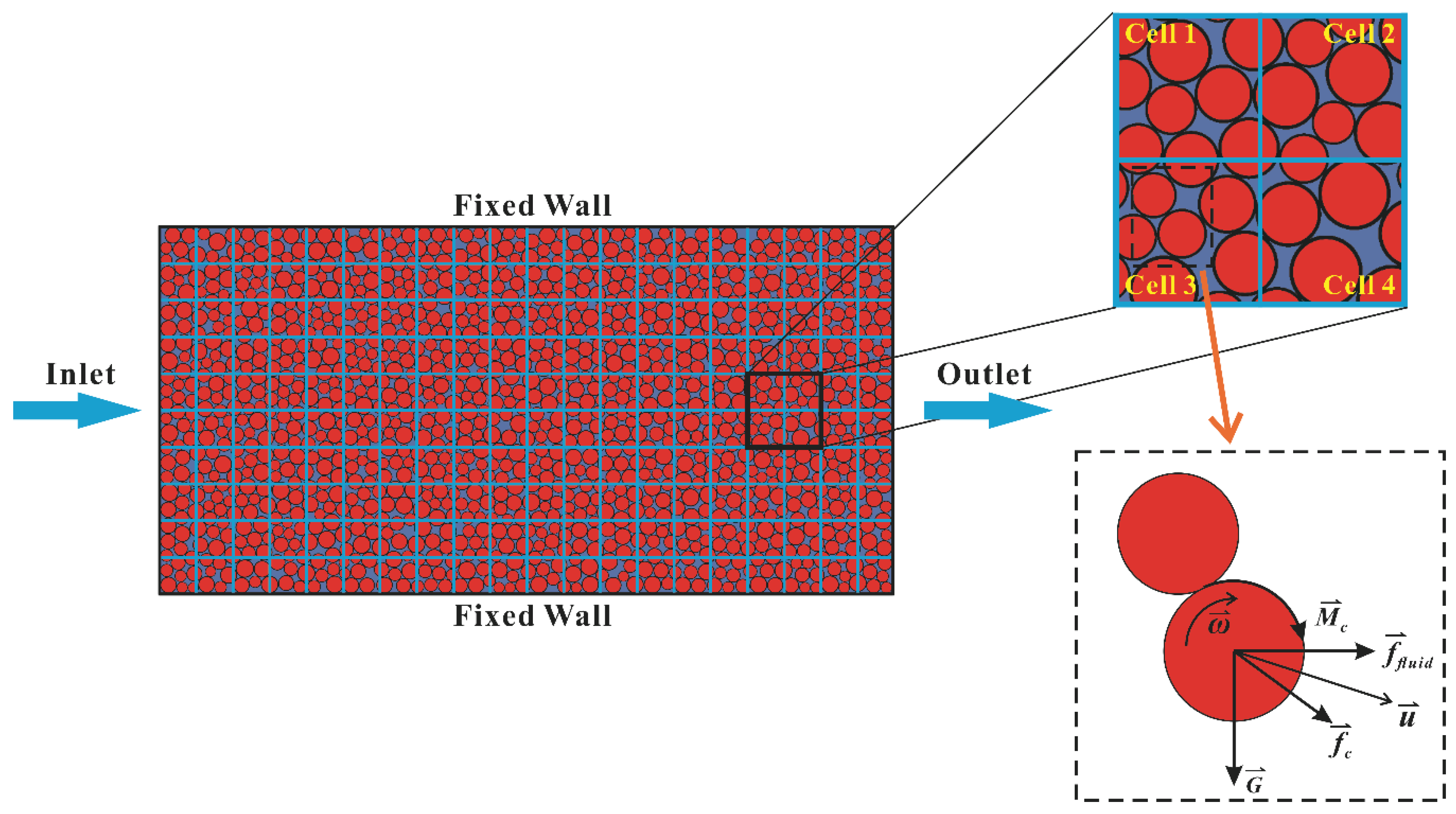
A schematic diagram of the fluid–particle interaction system in the fluid element is shown in Figure 3.
The fluid element should be sufficiently fine to resolve the flow structures. Thus, the following inequality should be met:
d c Δ x cfd > 5 ,
where d c is the minimum width of the flow domain, and Δ x cfd is the fluid cell length. This coupling methodology is designed to describe the average coupling forces occurring within one fluid cell. Flow around the particles is not explicitly represented because the local porosity is assumed to be evenly distributed within one fluid cell. For good results, several PFC3D particles should fit inside one CFD fluid cell:
Δ x cfd 2 r > 3 .
The coupling interval should be sufficiently small to resolve the desired coupling behaviour. Coupling information should be exchanged several times as a particle moves across a fluid cell. This condition is satisfied when the following inequality is met:
Δ x cfd | u | t c ,
where t c is the coupling interval [44].

2.2. Implementation of the Coupled CFD-DEM Model

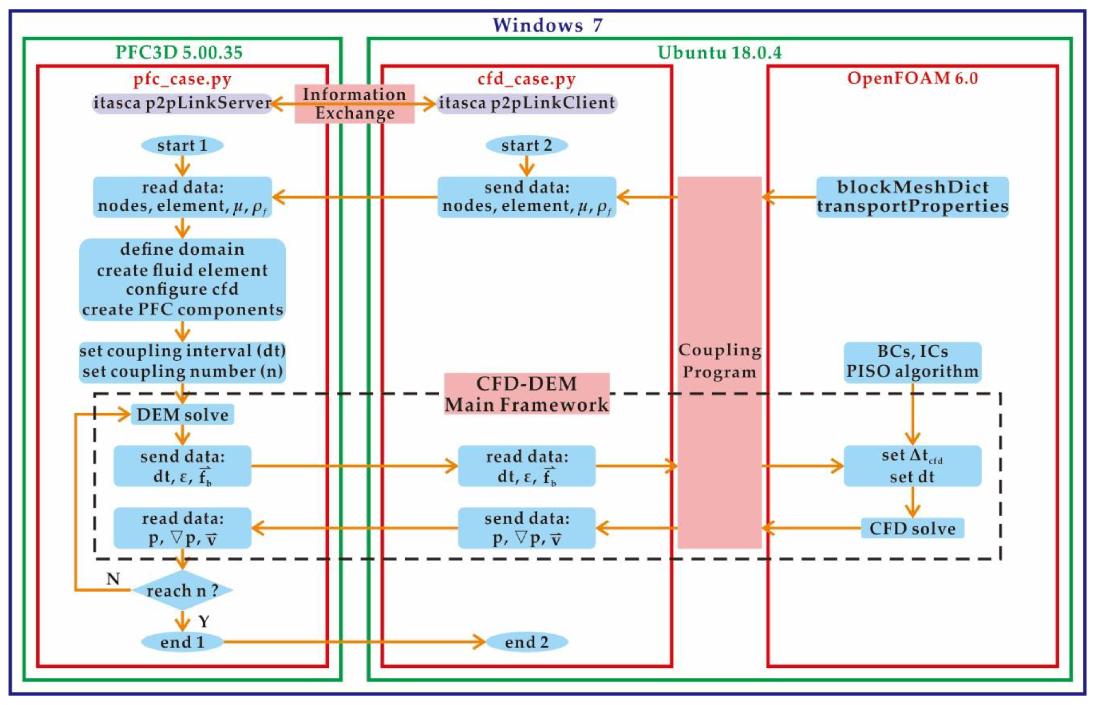
The novel, 3D, two-way coupled CFD-DEM model was implemented by coupling two codes: the open source code OpenFOAM for the CFD simulation and the commercial code PFC3D for the DEM simulation. To facilitate the coupling between OpenFOAM and PFC3D, a customized Python routine, pyDemIcoFoam, which was developed based on the open source codes from GitHub, was written to wrap and incorporate OpenFOAM into the Python environment. The coupling program was written in C++ and integrated in Python. Then, the p2pLink classes in the Python module of PFC3D were employed to exchange data between OpenFOAM and PFC3D in a Python environment. The flow chart of implementing the coupled CFD-DEM model is shown in Figure 4.
Before coupling calculations, it is necessary to determine the timesteps of both CFD and DEM, and the coupling interval. Based on the results of sensitivity analyses on the timestep [10], we set the timestep of CFD to 1.0 × 10 4 s and the timestep of the DEM to be in the range of 1.0 × 10 6 1.0 × 10 5 s. The coupling interval in the current work was set to 1.0 × 10 3 s. In addition, we should confirm that the link between CFD and DEM is connected successfully.
During each coupling calculation, when the CFD module of PFC3D is active, the fluid–particle interaction force f fluid is automatically calculated and applied to the PFC particles. After completing the DEM solving process, we employ the p2pLink classes to send the interaction force and porosity in each fluid cell to the CFD solver. The PISO algorithm [51] is used to solve the discretized pressure-velocity coupling equations in OpenFOAM. After performing the CFD calculations, we use the p2pLink classes again to send the fluid pressure, velocity and pressure gradient to the DEM solver. Thus, we finish one coupling calculation. The process continues until the condition for termination is reached.

2.3. Benchmarking Examples

It was instructive to benchmark the coupled CFD-DEM model first before our investigations. Two examples were chosen due to their simplicity and because their analytical solutions were available; hence, these examples often serve as benchmarks for the coupled CFD-DEM model. The first benchmark was a single spherical particle settling in still water, whereas the second benchmark was the classic problem of Darcy’s law.

2.3.1. A Single Spherical Particle Settling in Still Water

The first case was a simulation of a single spherical particle settling in still water. A spherical particle with a diameter of 1 mm and a density of 2650 kg / m 3 was released from the centre of a cubic tank with a side length of 0.1 m that was filling with still water. The porosity of the fluid cell in which the particle was placed was calculated to be 0.999. The motion of a single spherical particle was calculated analytically as follows:
4 3 π r 3 ρ p du z dt = 4 3 π r 3 ( ρ p ρ f ) g 1 2 π r 2 C d ρ f u z 2 ,
where r is the particle radius, ρ p is the particle density, ρ f is the fluid density, u z is the vertical velocity of the settling particle and C d is the drag force coefficient.
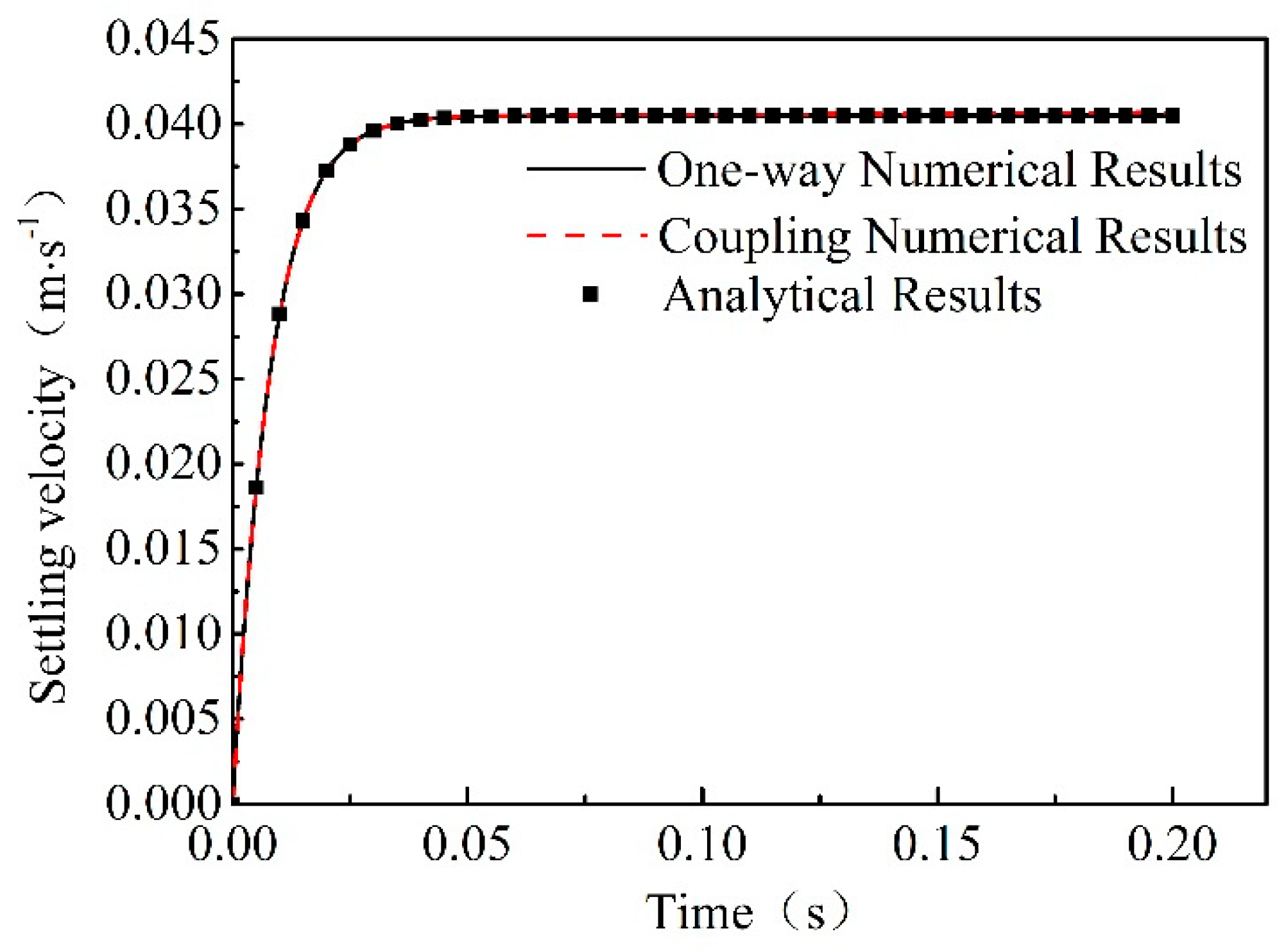
According to Equation (17), a forward finite difference algorithm achieved by Python programming language was used to calculate the theoretical vertical velocity of the settling particle at different times, which was expected to be comparable to the numerical solutions. Figure 5 shows that a single spherical particle settles from an initial static state and then accelerates until the settling terminal velocity is reached. The settling terminal velocity was 0.0406 m/s, which matches the analytical solution very well. The diagram of both fluid velocity and particle velocity is shown in Figure 6.

2.3.2. Darcy’s Law

Derived based on the experiments on water flowing through sand beds, Darcy’s law describes a linear relationship between the seepage velocity and the hydraulic gradient in porous media:
v = KI = k μ · p outlet p inlet L ,
where v is the seepage velocity; K is the permeability coefficient; I is the hydraulic gradient; μ is the fluid dynamic viscosity, p outlet is the pressure at the outlet; p inlet is the pressure at the inlet; L is the length of the flow path; and k is the intrinsic permeability coefficient, which can be estimated from the Kozeny–Carman relationship.
k = d 2 ε 2 180 ( 1 ε ) 2 ,
where ε is the porosity and d is the particle diameter.
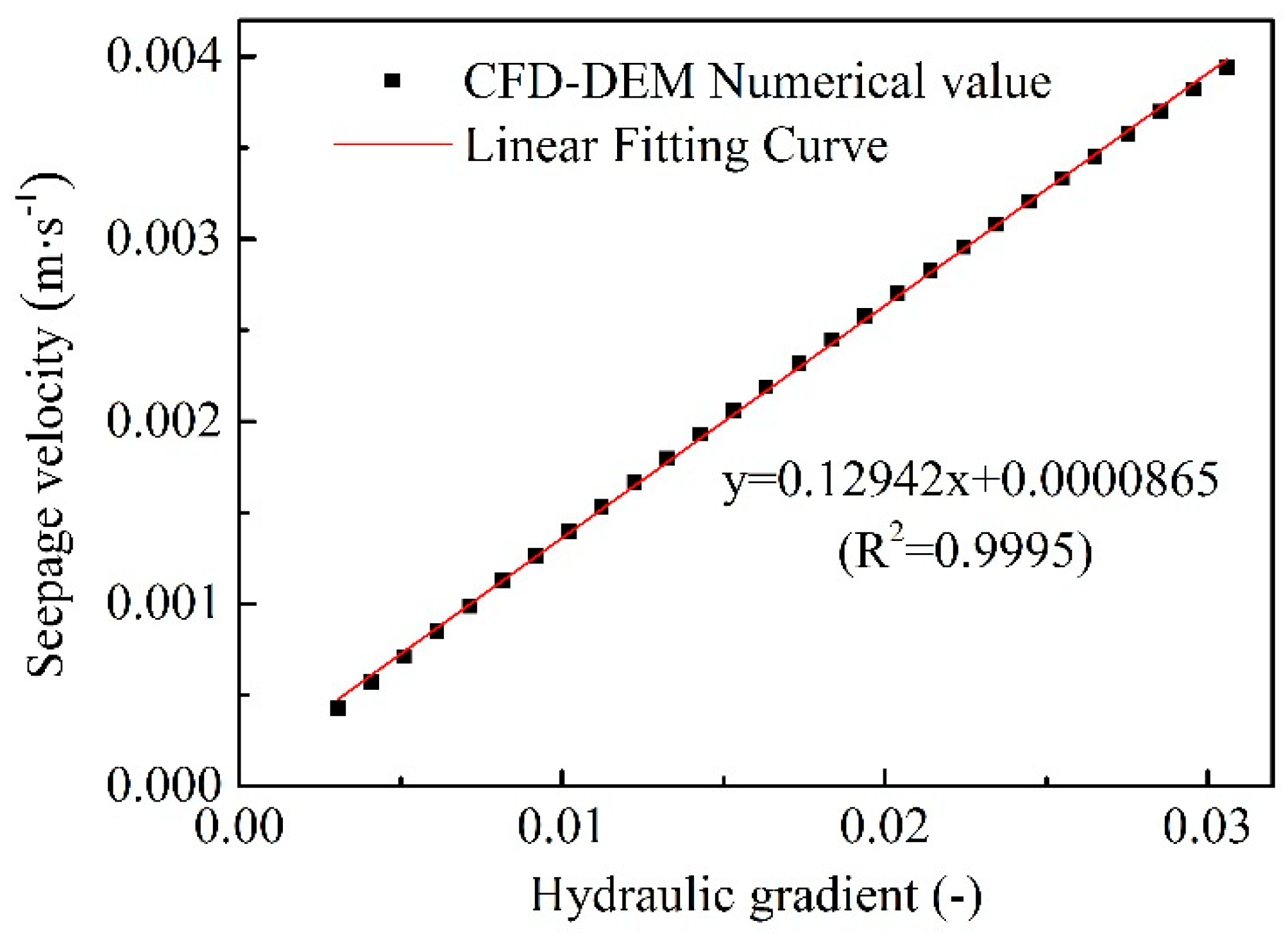
The experimental testing setup is illustrated in Figure 7, which consists of fluid and particle phases. The fluid phase was made up of a parallelepiped with dimensions of 0.05 × 0.1 × 0.05 m, and each fluid cell was a cube with a side length of 0.01 m. The particle phase was composed of regularly arranged particles with radii of 0.25 mm. Thus, each fluid cell contained 64 ( 4 3 ) particles, and the cell porosity was 0.476. According to Darcy’s law, we obtained the theoretical value of permeability: 0.1343 m/s. The back and front boundaries were set as the inlet and outlet of the model, and both were constant pressure boundary conditions; the inlet had various constant pressure values, whereas the outlet had a constant pressure of 0.0 Pa. When the Reynolds number of the particle ranged from 1 to 10, we could regard the flow regime as laminar flow and satisfy Darcy’s law. As the value of the inlet pressure changed, we obtained the seepage velocity with different hydraulic gradients, as shown in Figure 8. This figure shows that the result of the numerical simulation was consistent with the result of Darcy’s law, and the permeability coefficient from the fitting curve was 0.1294 m/s; the relative error between the analytical value and numerical value was 3.66%.

3. Flow Characteristics of Particles Inside a Pipe

3.1. Model Description

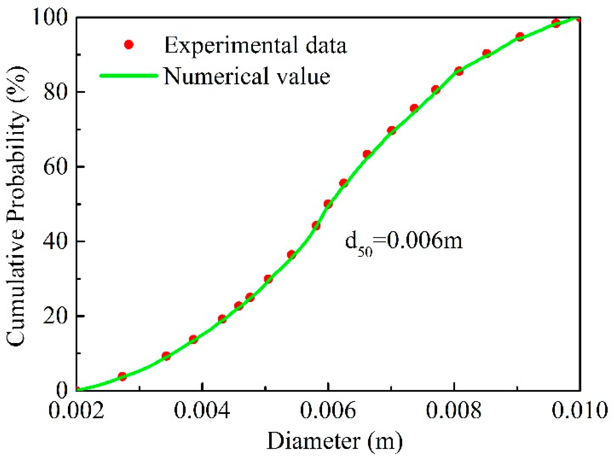
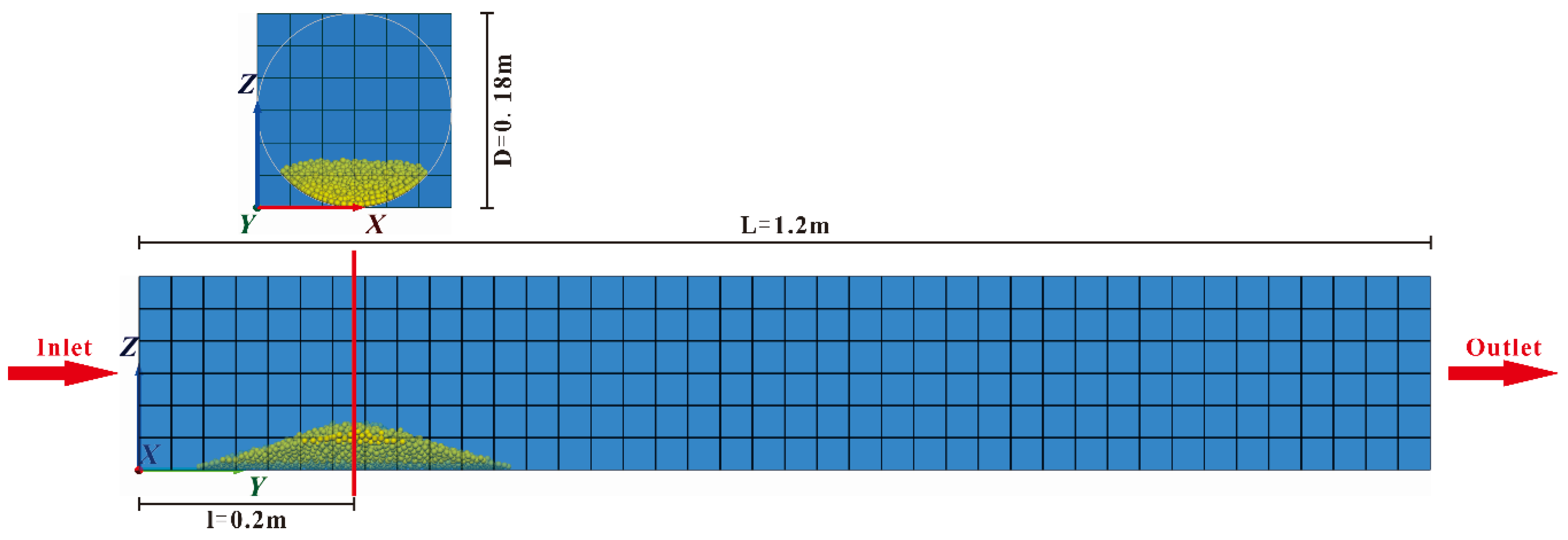
A 3D particle flow model was established to investigate the performance of particles in a fluid–particle interaction system. Particles were first generated and deposited inside a pipe under gravity and then subjected to erosion from flowing water. Six groups of particles were created and numbered D2, D4, D6, D8, D10 and DP6, where group D2 represents mono-sized particles with a particle size of 2 mm and group DP6 represents polydisperse particles with a controlled particle size d 50 of 6 mm. The comparison of the experimental data particle size curve and the numerically generated particle size curve are given in Figure 9. The accuracy met the research requirements. The pipe was assumed to have a length of 1.2 m and a diameter of 0.18 m. The entire fluid element that contained the entire pipe was a parallelepiped with dimensions of 0.18 × 1.2 × 0.18 m. Along the three axes of the fluid element, 6 × 40 × 6 fluid cells were divided, respectively, so each fluid cell was a cube with a side length of 0.03 m, as shown in Figure 10. The inlet was assumed to maintain a constant flow velocity of 0.5 m/s, and the outlet was assumed to have a constant pressure boundary of 0.0 Pa. All groups of particles had the same total volume and were generated at approximately 0.2 m from the inlet. All of the parameters of the particles and solving configurations are listed in Table 3. The same initial conditions and boundary conditions were applied during the implementation of different cases. After the particles stably settled in the pipe, a total of 1.0 s of actual physical time was simulated in the pipe inclination angle case, whereas 5.0 s was simulated in the other cases.

3.2. Results

In this section, a series of simulations are described. They were implemented to study the effects of particle size, polydisperse particles and pipe inclination angle on the flow characteristics of particles inside a pipe using the coupled CFD-DEM model presented herein, following the procedures described in Figure 4. All of the simulation results are described below. The results show that after the total simulation time, the particle profiles in every group become relatively stable.

3.2.1. Particle Flow Patterns

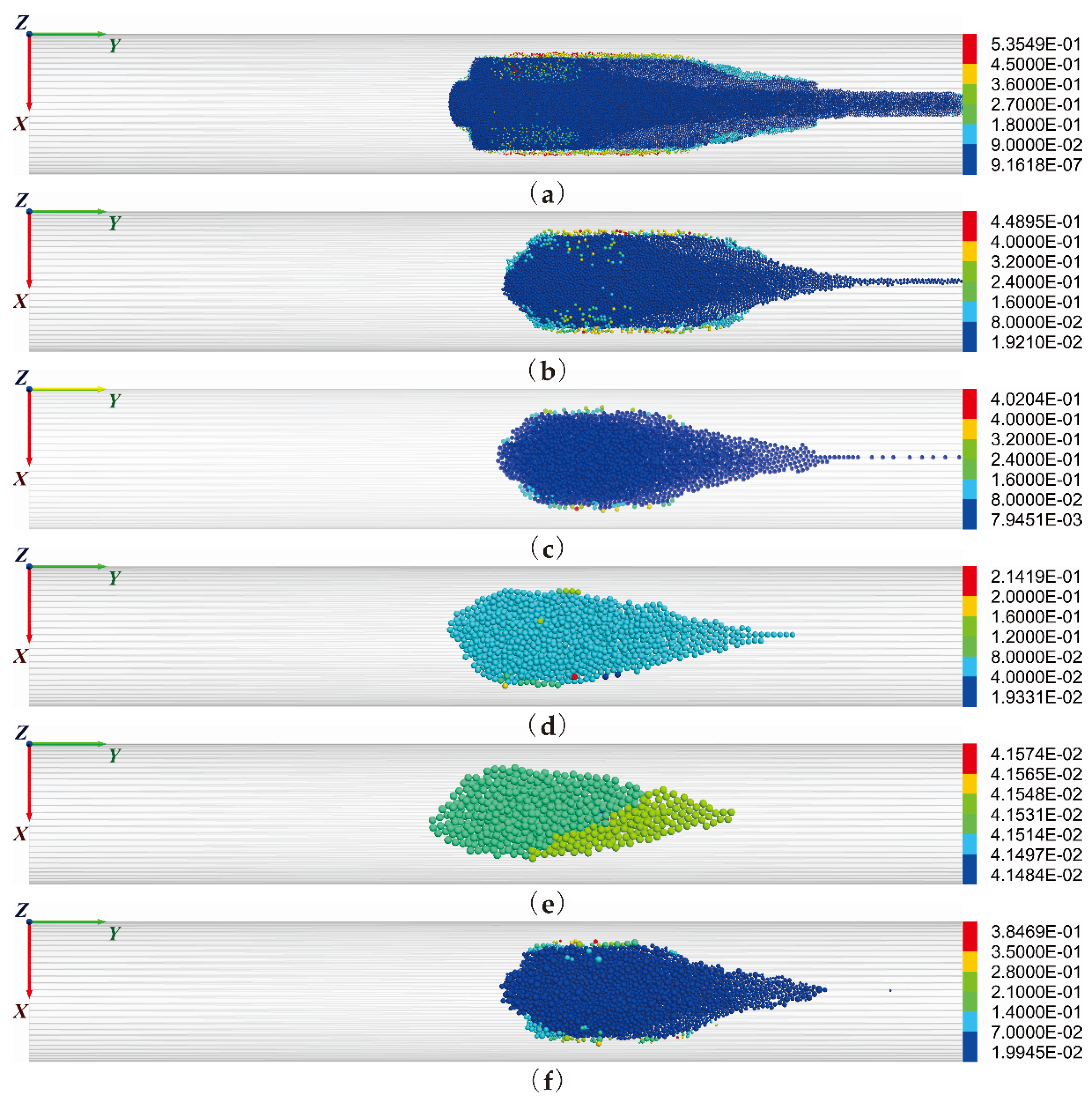
Figure 11 illustrates the particle flow patterns inside a horizontal pipe for the six groups after a total simulation time of 5 s. In general, all particle positions in each group were distributed symmetrically along the axis of the pipe. The smaller the particle size was, the more obvious the symmetry. The symmetry of group D2 was especially obvious, whereas groups D8 and D10 had weaker symmetry than the other groups. After carefully observing the six groups of particle flow patterns, we found that the particle flow patterns were composed of two parts: the tip part and the main part. A small number of particles with relatively large displacements formed the tip part, whereas the rest of the particles formed the main part. The smaller the particle size, the more obvious is the tip part. The tip part of group D10 basically disappeared. The phenomenon of particle movement flowing out of the right boundary of the pipe was found in groups D2, D4, D6 and DP6, but not in groups D8 and D10. The volume fractions of outflow particles in groups D2, D4, D6 and DP6 were 5.62%, 1.38%, 0.13% and 0.064%, respectively. After 5 s of fluid effects, each group of particles moved some distance forward from the initial position set during particle generation. This finding indicates that the drag force of the fluid affecting the particles is greater than that of the friction force at the bottom of the pipe when the inlet velocity of the fluid is 0.5 m/s. For mono-sized particles (as shown in Figure 11a–e), the particle flow patterns satisfy all the features of symmetry and the abovementioned tip part. The volume fraction of the outflow particle decreases with increasing particle size. For polydisperse particles (as shown in Figure 11c,f), the symmetry of the particle distribution was similar to that in group D6. The tip part in group DP6 was less obvious than that in group D6. The volume fraction of the outflow particles in group DP6 was much smaller than that in group D6. Hence, the overall fluidity of group DP6 was much better than that of group D6.

3.2.2. Particle Flow Velocity

In general, Figure 11 shows that in the overall distribution of particle flow velocity, the high-speed particles revolve around the low-speed particles and are distributed symmetrically on both sides of the pipe; these phenomena were especially obvious for groups D2 and D4 (as shown in Figure 11a,b) and were not substantial in groups D8 and D10. The particles of maximum velocity were symmetrically distributed on both sides of the particle heap. For mono-sized particles (as shown in Figure 11a–e), with an increase in the particle size, the maximum particle velocity decreases, the presence of high-speed particles becomes less apparent, and the range of particle velocity distribution narrows. Hence, the particle velocity distribution tends to average, and, especially in group D10, the particle velocities are basically the same. For polydisperse particles (as shown in Figure 11c–e) in group DP6, the maximum particle velocity was slightly lower and the range of particle velocity distribution was less narrow than that in group D6. The overall difference between groups D6 and DP6 in terms of particle velocity was small.
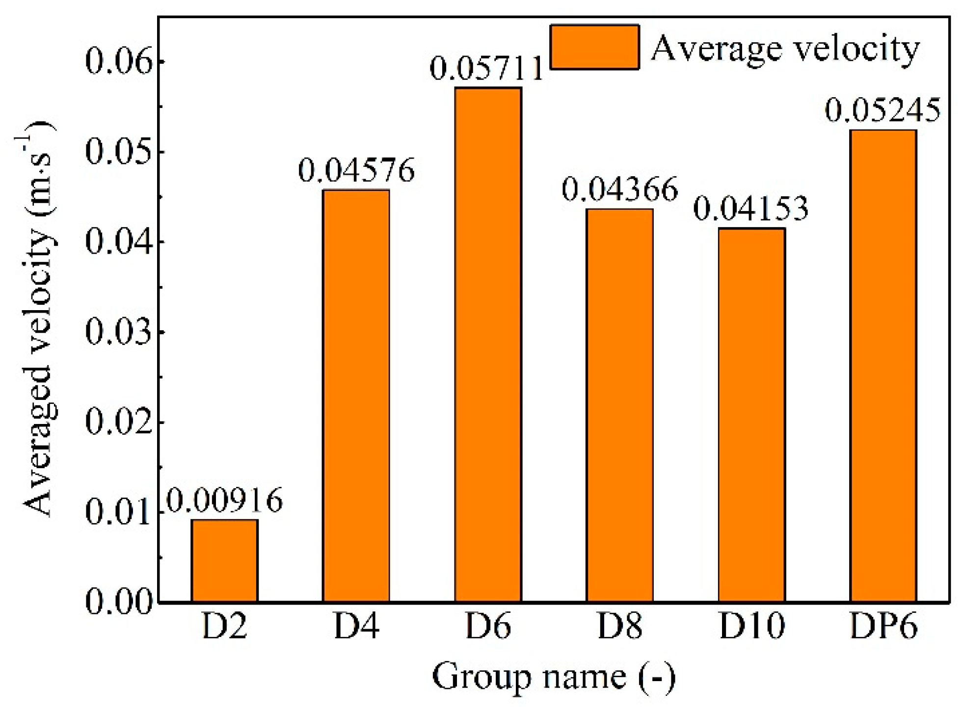
The average velocities of the total particle phases in different groups were calculated and are shown in Figure 12. For mono-sized particles, with an increase in the particle size, the average particle velocity first increased and then decreased, and finally reached the maximum value in group D6. The average velocity of group D2 was much lower than that of group D10. For polydisperse particles, the average velocity of group DP6 was slightly lower than that of group D6.
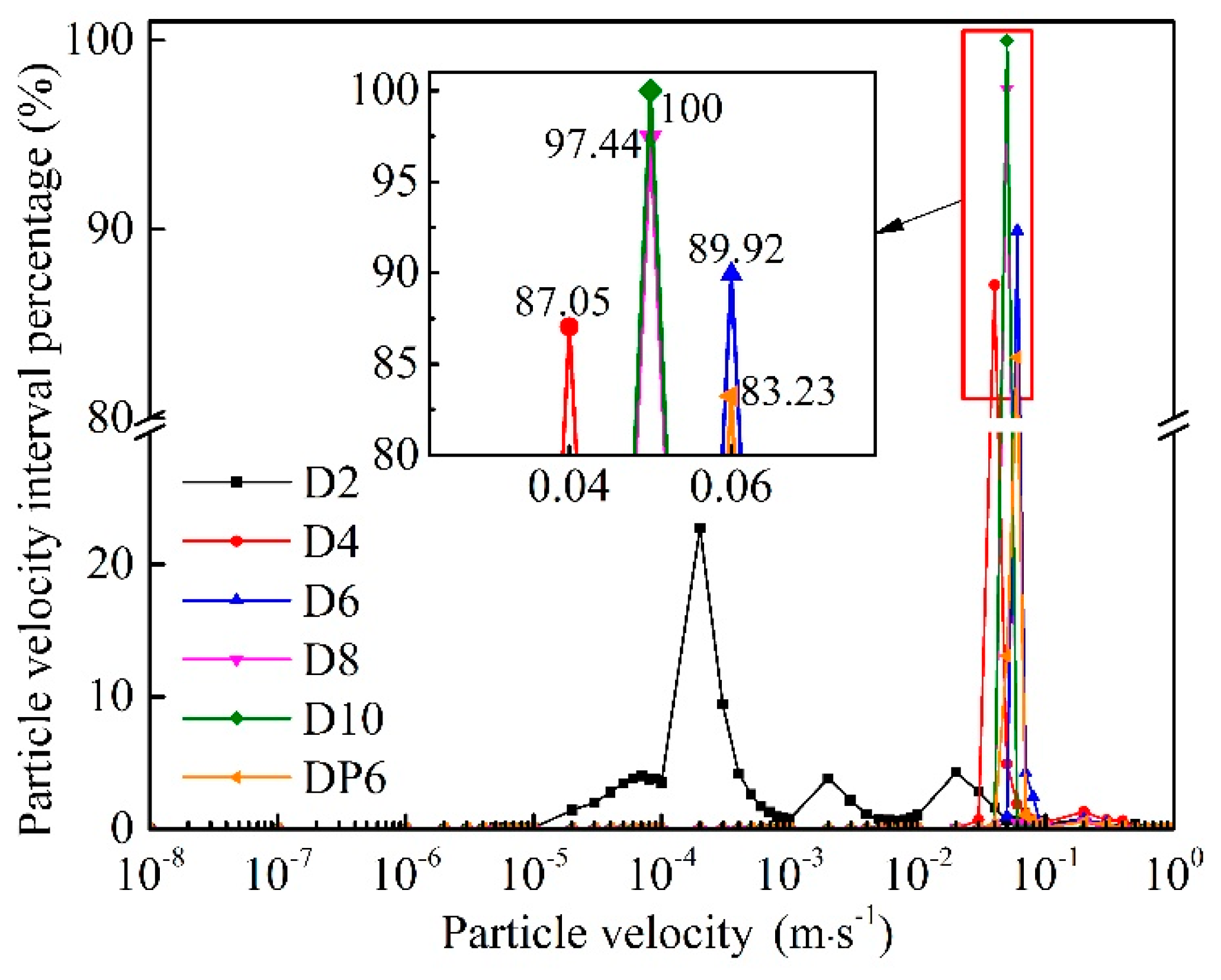
Figure 13 shows the particle velocity distribution curves. This figure shows that for mono-sized particles, with an increase in the particle size, the percentage of the maximum particle velocity interval is greater. The particle velocity is concentrated in some small areas, which indicates that the particle velocity gradually tends to be consistent and the tip part is weakened. In particular, the percentage of the maximum particle velocity interval in group D10 is 100%, which means that all particle velocities were distributed in the range of 0.04148–0.04157 m/s. The particle velocity distribution was relatively uniform in group D2. This finding is completely consistent with the particle flow pattern shown in Figure 11e. For polydisperse particles, the particle velocity distribution of group DP6 was similar to that of group D6.

3.2.3. Particle Erosion Rate and Kinetic Energy

The rate of particle erosion by fluid flow is expressed using the percentage of particle volume passing a certain position as the determinant criteria for erosive particles. Figure 14 shows that for mono-sized particles, with an increase in the particle size, the erosion rate of particles first increases and then decreases and reaches the maximum erosion rate in group D6. The difference between group D2 and D10 was not significant. This result is consistent with the maximum average particle velocity obtained in Figure 12. The erosion rate in the case of polydisperse particles is slightly higher than that in the case of mono-sized particles. This phenomenon can be interpreted as the fact that small particles can flow through the pores formed by large particles, which can reduce the tip part and improve the overall mobility of particles.
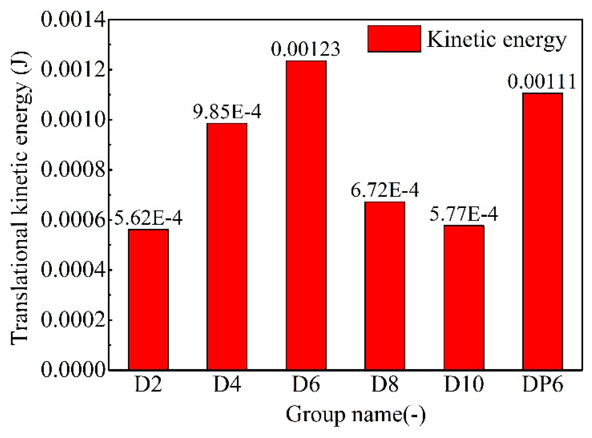
The total translational kinetic energy of the entire particle phase in different groups is calculated and shown in Figure 15. From Figure 15, we can conclude that for mono-sized particles, with an increase in the particle size, the kinetic energy of particles first increases and then decreases and reaches the maximum value in group D6. The kinetic energy in the polydisperse particles is lower than that in the mono-sized particles. The results agree with the regulation of average particle velocity.

3.2.4. Fluid Flow Behaviours

Overall, the behaviours of fluid flow in different groups predicted by this model are similar. Therefore, herein, we take the case of D6 as an example to explain the fluid flow behaviours in the fluid–particle interaction system. The fluid velocity vector diagrams of the D6 case at 5.0 s are shown in Figure 16. We used ParaView 5.4.0 to generate this figure. Figure 16 shows that the fluid field presents an uneven distribution. In contrast to the average velocity of the particle phase, the average velocity of the fluid phase is relatively singular and close to the inlet velocity of 0.5 m/s. The fluid velocity vectors of the fluid cells without particles are oriented towards the outlet of the fluid field, and the corresponding velocities are high. The fluid velocity vectors of the fluid cells with particles must be partially deflected, and the corresponding velocities are smaller than those observed in the fluid cells without particles. The deflection mode adapts to the shape of the particle heap: on the left side of the particle heap, the fluid vector is deflected upward, whereas on the right side of the particle heap, the fluid vector is deflected downward. For mono-sized particles, the maximum fluid velocity decreases with an increase in the particle size. For polydisperse particles, the maximum fluid velocity is smaller than that in the case of mono-sized particles.
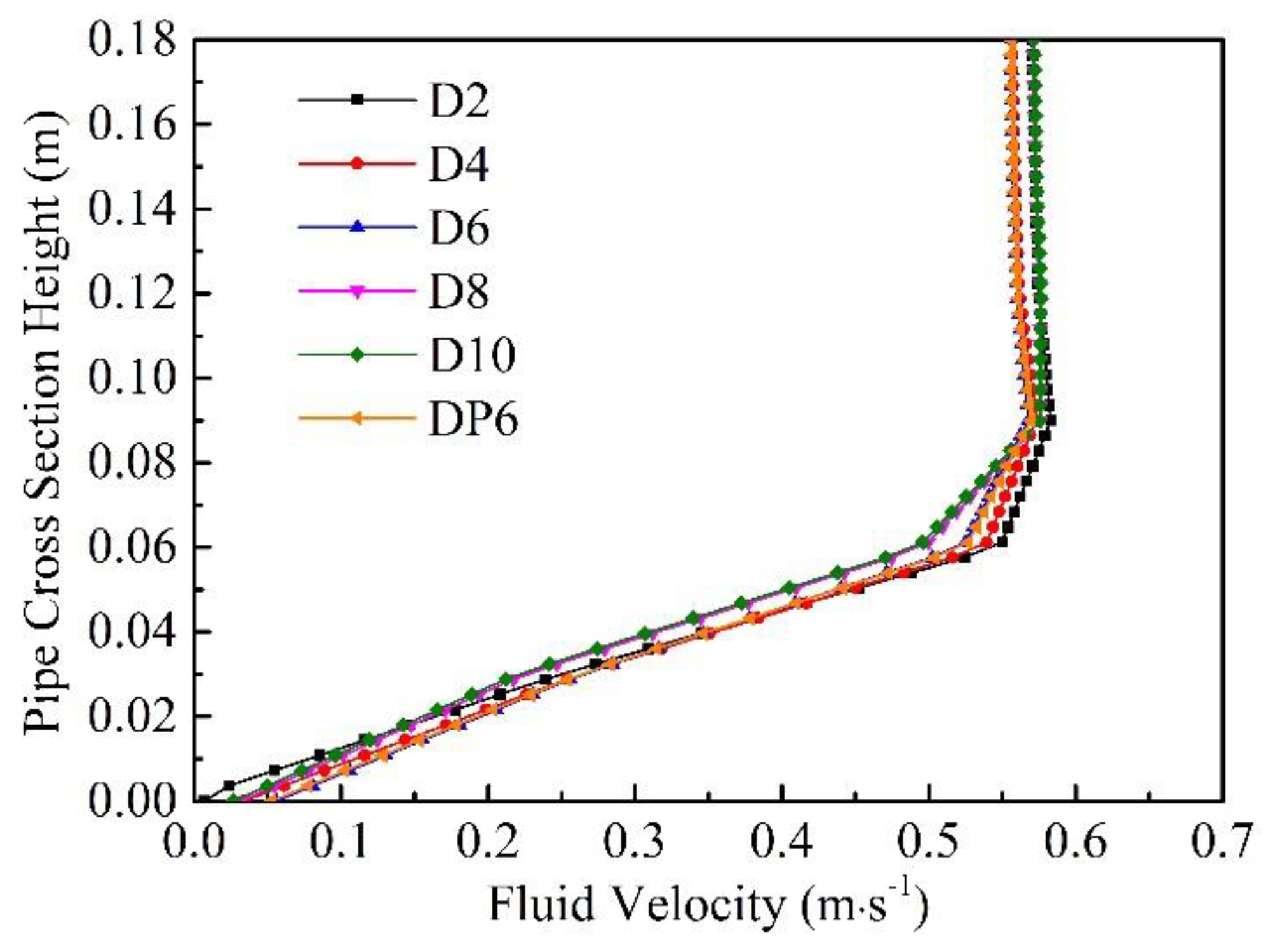
Figure 17 shows the flow velocity distribution along the centre line of the cross section at y = 0.7 m. In contrast to a pure pile flow, the overall velocity profile shifts upwards under the influence of the particle pile. In general, the velocity profiles of the six groups exhibit the same trend and can be divided into three parts. The first part is the slow acceleration stage. In this part, which intercepts the particle pile at the bottom, all of the groups have the same acceleration, except group D2, which is slightly slower than the others. The second part is the fast acceleration stage. In this part, groups D2, D4, D6 and DP6 have the same acceleration; moreover, groups D8 and D10 have the same acceleration, which is slightly slower than that in the other groups. The third part is the stabilization stage. In this part, the velocity first reaches its maximum, then slightly decreases, and finally remains relatively stable. The stable value is between 0.55 and 0.60 m/s.

3.2.5. Pipe Inclination Angle

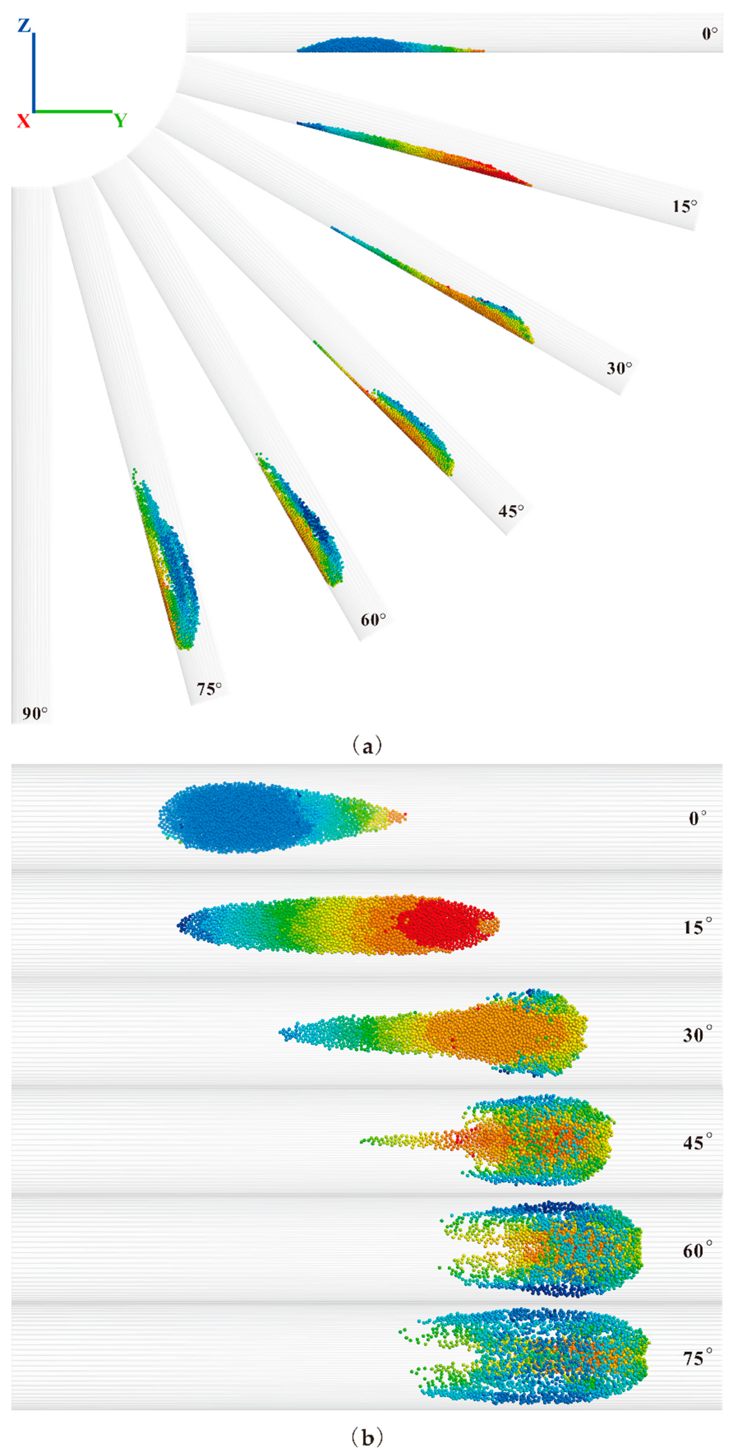
Figure 18 shows the effects of different pipe inclination angles on particle flow characteristics from different coordinate directions. Particles in each pipe inclination angle case were mono-sized, and the particle size was 6 mm (i.e., the same as that in group D6). We simulated the particle flow characteristics at the same inlet velocity of 0.5 m/s and an actual physical time of 1.0 s. In general, the inclination of the pipe has a significant effect on the flow characteristics of particles. Figure 18 shows that with an increase in the inclination angle of the pipe from 0° to 90°, the particles exhibited a considerably different performance. At that point, particle flow is the result of a combination of fluid and gravity. When the inclination angle is 0°, the particles only move forward under the effect of the fluid, presenting the main part and the tip part described above. The maximum velocity particles are distributed in the tip part, and the fluid effect is dominant (as shown in Figure 18a,b (0°)). When the inclination angle is 15°, the particles appear as a long strip, evenly arranged along the bottom of the pipe under the joint effects of fluid and gravity (as shown in Figure 18a,b (15°)). At this time, the gravitational effect gradually increases, and the maximum velocity is distributed in the front part of the long strip. When the inclination angle increases to 30° and 45°, the flow state of the particles changes significantly (as shown in Figure 18a,b (30°) and (45°)). Due to the friction of the inner wall of the pipe, the particles in the front part begin to gradually lag behind the particles in the middle part. Under the effect of the difference in velocity between the front part and the middle part, the particles on both sides of the front part move backwards, and at that time, the maximum velocity particles gradually distribute to the middle part of the particles. However, when the inclination angle increases to 60° and 75°, the particle velocity in the middle part is much higher than the particle velocity on both sides. Thus, the trailing part that appears in 30° and 45° gradually disappears, thereby forming an ellipsoidal particle group. Moreover, the particle flying phenomenon occurs in the case of 75°, at which time gravity takes the lead (as shown in Figure 18a,b (60°) and (75°)). When the inclination angle increases to 90°, all of the particles leave the pipe during the simulation time (as shown in Figure 18a (90°)).

4. Discussion

4.1. Coupled CFD-DEM Model

The novel, coupled CFD-DEM model proposed in this paper employed two types of the most commonly-used software for coupling, which fully utilized the advantages of both approaches, and comprehensively considered the economy and functionality of the model. The realization of the model had practical significance for the development of the CFD-DEM method. The flow chart of the coupling calculation was illustrated, which clearly interpreted every coupling calculation procedure. Two classic geo-mechanics problems were used to verify the model, and the results showed that the precision of the model can meet the research requirements. Then, the model was used to study the flow characteristics of particles inside a pipe. The results of this study were consistent with the results of previous studies but provided higher accuracy and computational efficiency, which further showed that the model was reliable for solving problems related to fluid–particle interaction systems. Thus, the proposed model can provide references for solving similar problems.
This paper is a preliminary study on the flow characteristics of particles inside a pipe. Particle flow characteristics are influenced by many factors. Only three major influencing factors were chosen in our study. To control the computation time, we used sparse particle systems in the investigation. In future research, studies on dense particle systems, non-orthogonal fluid meshing, varying fluid inlet velocities and other factors should be added for more comprehensive simulations.

4.2. Analysis of the Flow Characteristics of Particles Inside a Pipe

The simulation results were analysed from three aspects: particle characteristics, fluid characteristics and pipe inclination angle effects. The detailed analysis is described hereafter.
  • Particle characteristics: (1) The particle position distribution and particle velocity distribution have symmetry, and the degree of symmetry is negatively correlated with the particle size. (2) The particle flow pattern has an obvious tip part and a main part, and the presence of the tip part is negatively correlated with the particle size. (3) The phenomenon of the particle outflow boundary and the volume fraction of outflow particles are negatively correlated with the particle size. (4) The maximum particle velocity and the particle velocity distribution range are negatively correlated with the particle size. (5) The percentage of the maximum velocity interval is positively correlated with the particle size. (6) The average particle velocity, particle erosion rate and kinetic energy all increased first and then decreased with an increase in the particle size.
  • Fluid characteristics: The fluid field exhibits an uneven distribution. The presence of particles can impede the water flow and deflect the fluid velocity vector. The deflection mode adapts to the shape of the particle heap. The maximum fluid velocity is negatively correlated with the particle size. The flow velocity distribution along the centre line of the cross section shows the same trend and can be divided into three parts: a slow acceleration stage, fast acceleration stage and stabilization stage.
  • The effects of the pipe inclination angles: There is a threshold for particle escape velocity inside a pipe. With an increase in the pipe inclination angle, the positive stress decreases, the friction force of the particles decreases, and the sliding force increases. Due to the combined action of the fluid drag force, the larger the inclination angle is, the smaller is the escape velocity threshold of the particle. As the inclination angle of the pipe gradually increases from 0° to 90°, the particles exhibit a significantly different performance. When the inclination angle is 0°, particles present the normal main and tip parts. When the inclination angle is 15°, particles appear as long strips that are evenly arranged along the bottom of the pipe. When the inclination angles are 30° and 45°, the particles present in the front part gradually lag behind the particles in the middle part and form the trailing part. When the inclination angles are 60° and 75°, the tailing part gradually disappears, forms an ellipsoidal particle group and exhibits a particle flying phenomenon. When the inclination angle is 90°, all of the particles leave the pipe.

5. Conclusions

The novel, 3D, two-way coupled CFD-DEM model developed in this paper was implemented by coupling two software programs, OpenFOAM and PFC3D. This model can make accurate predictions for problems related to particles flowing in water. The model used in this study had higher accuracy and calculation efficiency than the models used in previous studies. Therefore, the proposed model can provide valuable references for solving soil erosion and bridge scour problems. The model was presented as follows: (1) the governing equations for both the fluid phase and the particle phase, and the fluid–particle interaction force were presented; (2) the coupling scheme was explained in detail, and the flow chart of coupling calculations was clearly presented; and (3) the model was benchmarked with two classic geo-mechanics problems, thereby verifying the accuracy of the model. Moreover, this model was applied to study the effects of particle size, polydisperse particles and pipe inclination angles on the flow characteristics of particles inside a pipe. The results showed that particle size and pipe inclination angle can considerably affect the particle flow morphology, kinetic energy and erosion rate, whereas polydisperse particles had a slight effect. These findings further demonstrated the reliability of the model.

Author Contributions

Software, validation and writing—original draft, H.Z.; funding acquisition, conceptualization and methodology, G.W.; writing—reviewing and editing, C.J.; visualization, C.L.

Funding

This research was funded by the Groundwater Safety Control Technology for Urban Rail Transit Project Construction (No. 3-4-2018-008).

Acknowledgments

The authors appreciate the Itasca Consulting Group Inc. programmer Furtney, J. for the important programming suggestions and basic code; programmer Netkidxp.CN for solving many programming problems; and Wang, H.X. for his help writing this paper.

Conflicts of Interest

The authors declare no conflict of interest.

Nomenclature

ρ f fluid density, kg · m 3
ρ p particle density, kg · m 3
ttime, s
mparticle mass, kg
v fluid velocity, m/s
u particle translational velocity, m/s
w particle annular velocity, rad/s
ε porosity, dimensionless
μ fluid dynamic viscosity, Pa · s
ν fluid kinematic viscosity, m 2 / s
rparticle radius, m
dparticle diameter, m
C d drag force coefficient, dimensionless
Re p Reynolds number of the particle, dimensionless
f d 0 drag force of the single particle, N
f d drag force, N
χ empirical coefficient to account for the local porosity, dimensionless
f buo buoyancy, N
f c contact force exerted by the neighbouring particles, N
f a externally applied force, N
f mesh the sum of additional forces applied on the particle, N
f p fluid pressure gradient force, N
f fluid the total fluid–particle interaction force applied on the particle by the fluid, N
pfluid pressure, Pa
p fluid pressure gradient, Pa/m
Ggravitation, N
M moment of contact force acting on the particle, N · m
I p moment of inertia for the particle, kg · m 2
f b the body force per unit volume exerted on the fluid by the particle, N
g gravitational acceleration, m / s 2
V p volume of the particle, m 3
u z vertical velocity of the settling particle, m/s
d c minimum width of the flow domain, m
Δ x cfd fluid element length, m
t c coupling interval, s
Kpermeability coefficient, m/s
Ihydraulic gradient, dimensionless
p inlet pressure at the inlet, Pa
p outlet pressure at the outlet, Pa
Llength of flow path, m
kintrinsic permeability coefficient, m 2
vseepage velocity, m/s

References

  1. Zhu, H.P.; Zhou, Z.Y.; Yang, R.Y.; Yu, A.B. Discrete particle simulation of particulate systems: Theoretical developments. Chem. Eng. Sci. 2007, 62, 3378–3396. [Google Scholar] [CrossRef]
  2. Zhu, H.P.; Zhou, Z.Y.; Yang, R.Y.; Yu, A.B. Discrete particle simulation of particulate systems: A review of major applications and findings. Chem. Eng. Sci. 2008, 63, 5728–5770. [Google Scholar] [CrossRef]
  3. Peters, B.; Baniasadi, M.; Baniasadi, M. XDEM multi-physics and multi-scale simulation technology: Review of DEM-CFD coupling, methodology and engineering applications. Particuology 2019, 44, 176–193. [Google Scholar] [CrossRef]
  4. Manjula, E.V.P.J.; Ariyaratne, W.K.H.; Ratnayake, C. A review of CFD modelling studies on pneumatic conveying and challenges in modelling offshore drill cuttings transport. Powder Technol. 2017, 305, 782–793. [Google Scholar] [CrossRef]
  5. Kuang, S.B.; Zhou, M.M.; Yu, A.B. CFD-DEM modelling and simulation of pneumatic conveying: A review. Powder Technol. 2019, in press. [Google Scholar] [CrossRef]
  6. Guo, Y.; Yu, X.B. Comparison of the implementation of three common types of coupled CFD-DEM model for simulating soil surface erosion. Int. J. Multiph. Flow 2017, 91, 89–100. [Google Scholar] [CrossRef]
  7. Cundall, P.A.; Strack, O.D.L. A discrete numerical model for granular assemblies. Geotechnique 1979, 29, 47–65. [Google Scholar] [CrossRef]
  8. Furtney, J.; Zhang, F.; Han, Y. Review of Methods and Applications for Incorporating Fluid Flow in the Discrete Element Method; Itasca Consulting Group Inc.: Minneapolis, MN, USA, 2013. [Google Scholar]
  9. Goniva, C.; Kloss, C.; Hager, A. An open source CFD-DEM perspective. In Proceedings of the Openfoam Workshop, Gothenburg, Sweden, 21–24 June 2010. [Google Scholar]
  10. Tsuji, Y.; Kawaguchi, T.; Tanaka, T. Discrete particle simulation of two-dimensional fluidized bed. Powder Technol. 1993, 77, 79–87. [Google Scholar] [CrossRef]
  11. Han, Y.H. Construction of a LBM-DEM Coupling System and its Applications in Modeling Fluid Particle Interaction in Porous Media Flow. Ph.D. Thesis, University of Minnesota, Minneapolis, MN, USA, 2012. [Google Scholar]
  12. Shadloo, M.S.; Oger, G.; Touzé, D.L. Smoothed particle hydrodynamics method for fluid flows, towards industrial applications: Motivations, current state, and challenges. Comput. Fluids 2016, 136, 11–34. [Google Scholar] [CrossRef]
  13. Hama, N.A.; Ouahbi, T.; Taibi, S. Analysis of mechanical behavior and internal stability of granular materials using discrete element method. Int. J. Numer. Anal. Meth. Geomech. 2016, 40, 1712–1729. [Google Scholar] [CrossRef]
  14. Akhshik, S.; Behzad, M.; Rajabi, M. CFD-DEM simulation of the hole cleaning process in a deviated well drilling: The effects of particle shape. Particuology 2016, 25, 72–82. [Google Scholar] [CrossRef]
  15. Chen, X.L.; Zhong, W.Q.; Zhou, X.G. CFD-DEM simulation of particle transport and deposition in pulmonary airway. Powder Technol. 2012, 228, 309–318. [Google Scholar] [CrossRef]
  16. Zhao, T.; Dai, F.; Xu, N.W. Coupled DEM-CFD investigation on the formation of landslide dams in narrow rivers. Landslides 2017, 14, 189–201. [Google Scholar] [CrossRef]
  17. Zhao, T.; Houlsby, G.T.; Utili, S. Investigation of granular batch sedimentation via DEM-CFD coupling. Granul. Matter 2014, 16, 921–932. [Google Scholar] [CrossRef]
  18. Gou, D.Z.; An, X.Z.; Yang, X.H. CFD-DEM modeling on air impact densification of equal spheres: Structure evolution, dynamics, and mechanism. Powder Technol. 2017, 322, 177–184. [Google Scholar] [CrossRef]
  19. Mondal, S.; Wu, C.; Sharma, M.M. Coupled CFD-DEM simulation of hydrodynamic bridging at constrictions. Int. J. Multiph. Flow 2016, 84, 245–263. [Google Scholar] [CrossRef]
  20. Ma, Z.; Wang, Y.; Ren, N.X.; Shi, W. A coupled CFD-DEM simulation of upward seepage flow in coarse sands. Mar. Georesour. Geotech. 2018, 37, 589–598. [Google Scholar] [CrossRef]
  21. Shan, T.; Zhao, J.D. A coupled CFD-DEM analysis of granular flow impacting on a water reservoir. Acta Mech. 2014, 225, 2449–2470. [Google Scholar] [CrossRef]
  22. Zhang, Z.L.; Liu, D.Y.; Zhuang, Y.M. CFD-DEM modeling of CO2 capture using Alkali Metal-based sorbents in a bubbling fluidized bed. Int. J. Chem. React. Eng. 2014, 12, 441–449. [Google Scholar] [CrossRef]
  23. Lim, E.W.C.; Zhang, Y.; Wang, C. Effects of an electrostatic field in pneumatic conveying of granular materials through inclined and vertical pipes. Chem. Eng. Sci. 2006, 61, 7889–7908. [Google Scholar] [CrossRef]
  24. Tang, Z.J.; Yu, L.M.; Wang, F.H. Effect of particle size and shape on separation in a hydrocyclone. Water 2019, 11, 16. [Google Scholar] [CrossRef]
  25. Shamy, U.E.; Zeghal, M. A micro-mechanical investigation of the dynamic response and liquefaction of saturated granular soils. Soil Dyn. Earthq. Eng. 2007, 27, 712–729. [Google Scholar] [CrossRef]
  26. Zhao, J.D.; Shan, T. Coupled CFD-DEM simulation of fluid-particle interaction in geomechanics. Powder Technol. 2013, 239, 248–258. [Google Scholar] [CrossRef]
  27. Mao, H.T.; Wang, X.J.; Wang, Z.C. Seepage of saturated coarse soil multi-scale coupling simulation with dynamic water level. Chin. J. Rock. Mech. Eng. 2018, 37, 3797–3804. [Google Scholar]
  28. Dai, X.; Zheng, G.; Cheng, X.S. Numerical simulation of ground movement induced by leakage of groundwater and sand in excavations based on the DEM-CFD method. Chin. J. Rock. Mech. Eng. 2019, 38, 396–408. [Google Scholar]
  29. Shamy, U.E.; Aydin, F. Multiscale Modeling of Flood-Induced Piping in River Levees. J. Geotech. Geoenviron. 2008, 134, 1385–1398. [Google Scholar] [CrossRef]
  30. Climent, N.; Arroyo, M.; O’Sullivan, C.; Gens, A. Sand production simulation coupling DEM with CFD. Eur. J. Environ. Civ. En. 2014, 18, 983–1008. [Google Scholar] [CrossRef]
  31. Ren, L.B. A Parallel CFD-DEM Coupling Model and Numerical Simulation of Dense Particulate Two-phase Flows. Ph.D. Thesis, Shandong Universe, Jinan, China, 2015. [Google Scholar]
  32. Shao, B.; Yan, Y.F.; Bi, C.F. Migration of irregular cuttings particles in big size by CFD-DEM coupled simulation model. Sci. Technol. Eng. 2017, 17, 190–195. [Google Scholar]
  33. Zhang, F.; Huang, H. Coupled DEM-CFD Modeling of Fluid Injection into Granular Media. Aquac. Res. 2011, 31, 481–483. [Google Scholar]
  34. Zhou, J.; Yao, Z.X.; Zhang, G. Mesomechanical simulation of seepage flow in sandy soil. Chin. J. Geotech. Eng. 2007, 29, 977–981. [Google Scholar]
  35. Katagiri, J.; Konno, Y.; Yoneda, J. Pore-scale modeling of flow in particle packs containing grain-coating and pore-filling hydrates: Verification of a Kozeny—Carman-based permeability reduction model. J. Nat. Gas Sci. Eng. 2017, 45, 537–551. [Google Scholar] [CrossRef]
  36. Al-Arkawazi, S.; Marie, C.; Benhabib, K. Modeling the hydrodynamic forces between fluid-granular medium by coupling DEM-CFD. Chem. Eng. Res. Des. 2017, 117, 439–447. [Google Scholar] [CrossRef]
  37. Boyce, C.M.; Ozel, A.; Kolehmainen, J. Analysis of the effect of small amounts of liquid on gas-solid fluidization using CFD-DEM simulations. AIChE J. 2017, 63, 5290–5302. [Google Scholar] [CrossRef]
  38. Chen, F.; Drumm, E.C.; Guiochon, G. Coupled discrete element and finite volume solution of two classical soil mechanics problems. Comput. Geotech. 2011, 38, 638–647. [Google Scholar] [CrossRef]
  39. Li, P.C. Studies on Mechanism of Hydraulic Hoist of Coarse Particle in Vertical Pipe. Ph.D. Thesis, Tsinghua University, Beijing, China, 2007. [Google Scholar]
  40. Wu, L. Simulation of Liquid-Solid Two-Phase Flow with Coarse Particles in Pipes. Master’s Thesis, Hangzhou Dianzi University, Hangzhou, China, 2010. [Google Scholar]
  41. Anderson, T.B.; Jackson, R. A fluid mechanical description of fluidized beds: Equations of motion. Ind. End. Chem. Fundam. 1967, 6, 527–539. [Google Scholar] [CrossRef]
  42. Itasca Consulting Group Inc. PFC 5.0 Documentation; Itasca Consulting Group Inc.: Minneapolis, MN, USA, 2018. [Google Scholar]
  43. Shi, C.; Zhang, Q.; Wang, S.N. Numerical Simulation Technology and Application with Particle Flow Code (PFC5.0), 1st ed.; China Architecture & Building Press: Beijing, China, 2018; pp. 404–415. [Google Scholar]
  44. Felice, R.D. The voidage function for fluid-particle interaction systems. Int. J. Multiph. Flow 1994, 20, 153–159. [Google Scholar] [CrossRef]
  45. Xu, B.H.; Yu, A.B. Numerical simulation of the gas-solid flow in a fluidized bed by combining discrete particle method with computational fluid dynamics. Chem. Eng. Sci. 1997, 52, 2785–2809. [Google Scholar] [CrossRef]
  46. Komiwes, V.; Mege, P.; Meimon, Y. Simulation of granular flow in a fluid applied to sedimentation. Granul. Matter 2006, 8, 41–54. [Google Scholar] [CrossRef]
  47. Stokes, G.G. Mathematical and Physical Papers; Cambridge University Press: Cambridge, UK, 1901. [Google Scholar]
  48. Schiller, L.; Naumann, A. A drag coefficient correlation. Vdi Zeitung 1935, 77, 318–320. [Google Scholar]
  49. DallaValle, J.M. Micromeritics: The Technology of Fine Particles, 2nd ed.; Pitman Publishing Corp.: Chicago, IL, USA, 1948. [Google Scholar]
  50. Brown, P.; Lawler, D. Sphere drag and settling velocity revisited. J. Environ. Eng. 2003, 129, 222–231. [Google Scholar] [CrossRef]
  51. Issa, R.I. Solution of the implicitly discretized fluid flow equations by operator splitting. J. Comput. Phys. 1986, 62, 40–65. [Google Scholar] [CrossRef]
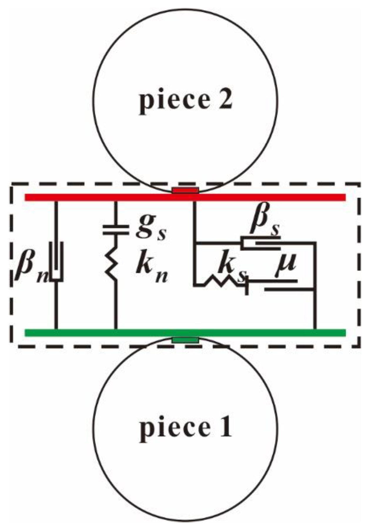
Figure 1. Schematic diagram of the linear contact model.
Water 11 02381 g001
Figure 2. Correlations of the drag force coefficient.
Water 11 02381 g002
Figure 3. Schematic diagram of the fluid–particle interaction system.
Water 11 02381 g003
Figure 4. Flow chart of implementing the coupled CFD-DEM model.
Water 11 02381 g004
Figure 5. Settling velocity of a single spherical particle.
Water 11 02381 g005
Figure 6. Diagram of both fluid velocity and particle velocity.
Water 11 02381 g006
Figure 7. Experimental setup for testing Darcy’s law.
Water 11 02381 g007
Figure 8. Variation in the seepage velocity with respect to the hydraulic gradient.
Water 11 02381 g008
Figure 9. Comparison of the experimental data and numerical values of polydisperse particles.
Water 11 02381 g009
Figure 10. Model of particles flowing inside a pipe.
Water 11 02381 g010
Figure 11. Schematic diagram of particle flow patterns and velocity: (a) D2 d p = 2   mm , (b) D4 d p = 4   mm , (c) D6 d p = 6   mm , (d) D8 d p = 8   mm , (e) D10 d p = 10   mm and (f) DP6 d 50 = 6   mm .
Water 11 02381 g011
Figure 12. Average velocity of the particle phase.
Water 11 02381 g012
Figure 13. Velocity distribution of particles in different groups.
Water 11 02381 g013
Figure 14. Particle erosion rates.
Water 11 02381 g014
Figure 15. Translational kinetic energy of the entire particle phase.
Water 11 02381 g015
Figure 16. Vector diagrams of fluid velocity.
Water 11 02381 g016
Figure 17. Fluid velocity along the cross section at y = 0.7 m.
Water 11 02381 g017
Figure 18. Particle flow velocities of different pipe inclination angles: (a) a view perpendicular to the YZ plane, and (b) a view parallel to the YZ plane and perpendicular to the pipe axis.
Water 11 02381 g018
Table 1. Specific implementation software of different coupled CFD-DEM models.
TypeSpecific Implementation SoftwarePractical Application
One commercial codeSTAR CCM+Akhshik, S. [14]
FluentRen, L.B. [31]
Two commercial codesFluent-EDEMChen, X.L. [15,32]
CCFD-PFC3DHama, N. A. [13,33,34]
COMSOL-PFC3DGuo, Y. [3]
One open source code and one commercial codeOpenFOAM-PFC3DKatagiri, J. [35]
Code_Saturne 1-SIGRAMEAl-Arkawazi, S. [36]
Two open source codesOpenFOAM-LIGGGHTSMa, Z. [20,37]
OpenFOAM-YADEChen, F. [38]
OpenFOAM-ESyS-Particle 2Zhao, T. [16,17]
Programming languageC++Li, C.P. [39]
Fortune 77Wu, L. [40]
1 Code_Saturne is a type of open source software for CFD. 2 ESyS-Particle is a type of open source software for DEM.
Table 2. Some well-established correlations of the drag force coefficient for spherical particles.
NameYearCorrelation
Newton [46]16870.44 Re p 100
Stokes [47]1880 24 Re p Re p 40
Schiller and Nauman [48]1935 { 24 Re p ( 1 + 0.15 Re p 0.687 ) 0.44 Re p 1000 Re p 1000
DallaValle [49]1948 ( 0.63 + 4.8 Re p ) 2 /
Brown and Lawler [50]2003 24 Re p ( 1 + 0.15 Re p 0.681 ) + 0.407 1 + 8710 Re p /
Table 3. Parameters used in the coupled CFD-DEM model.
ParameterValue
Particle diameter (mm)D2D4D6D8D10DP6
246810 d 50 = 6
Particle density ( kg / m 3 )2000
Effective modulus (Pa) 1.0 × 10 6
Normal-to-shear stiffness ratio (-)2.0
Particles friction coefficient (-, mm)Sliding friction coefficientRolling friction coefficient
0.30.2
Particle-wall friction coefficient (-, mm)Sliding friction coefficientRolling friction coefficient
0.10.1
Fluid density ( kg / m 3 )1000
Fluid dynamic viscosity ( Pa · s )0.001
DEM timestep (s) 1.0 × 10 6 1.0 × 10 5
CFD timestep (s) 1.0 × 10 4
Coupling interval (s)0.001
Total simulation time (s)5.0, 1.0