3.1. Model Arrangement
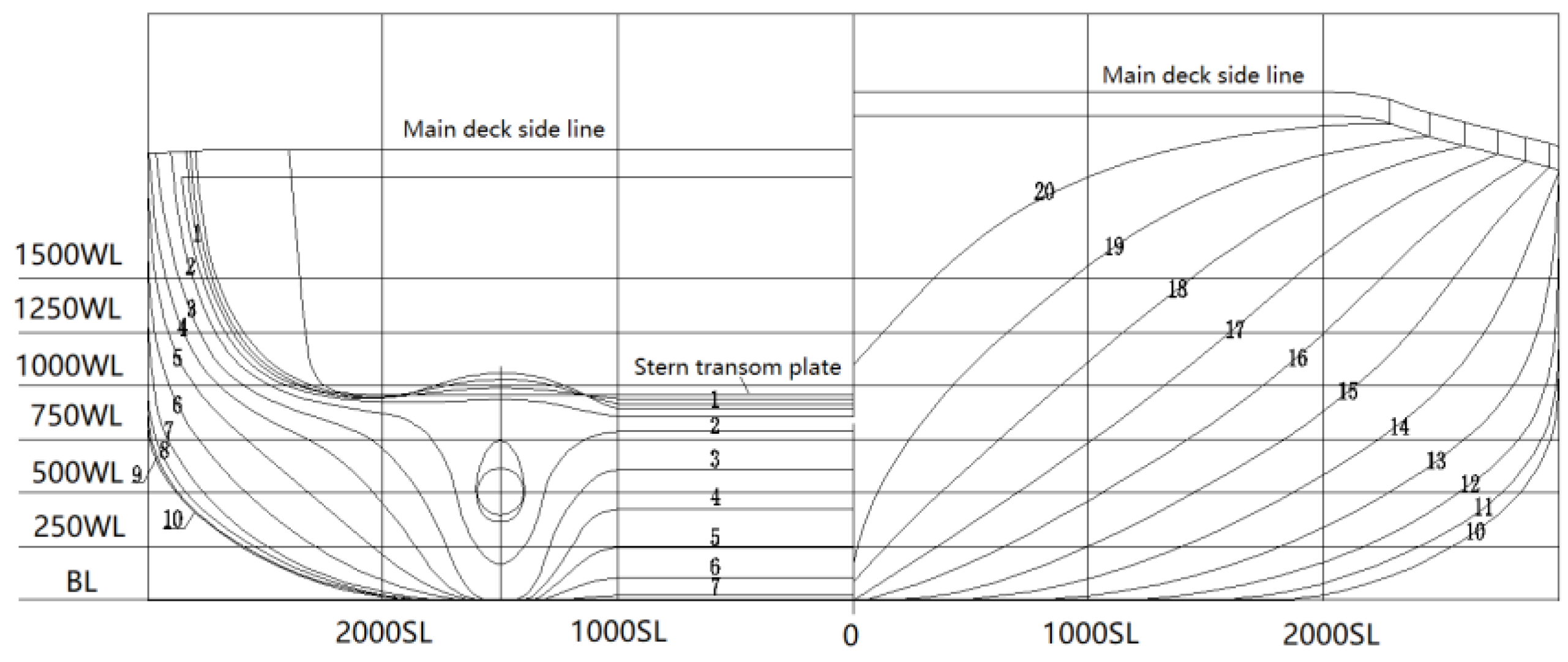
Several flooding cases were performed to study the effect of air compression on a damaged buoy tender. The utilized model is drawn on the basis of the existing lines plan with a full scale. Because the ship is a River buoy tender (WLR), the size is relatively small. The main particulars of the ship are given in
Table 2, while the views of the body plan and the damaged model are respectively shown in
Figure 2 and
Figure 3.
As illustrated in
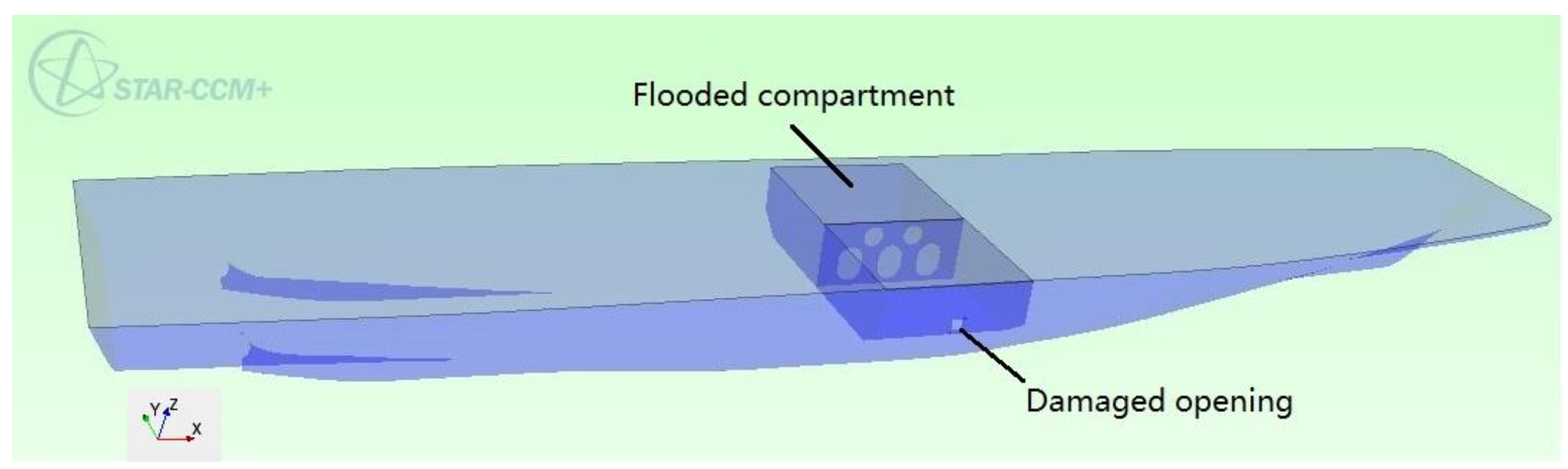
Figure 4, the damaged ship is placed in quasi-static water, ignoring the effect of wind and waves. The flooded compartment is placed in the middle of the ship. The damaged opening occurs on the starboard side of the flooded compartment, and the center point of the opening is at the midpoint of the ship length. The calculating displacement is set at 130 tons, allowing the initial free surface to completely submerge the damaged opening. As illustrated in
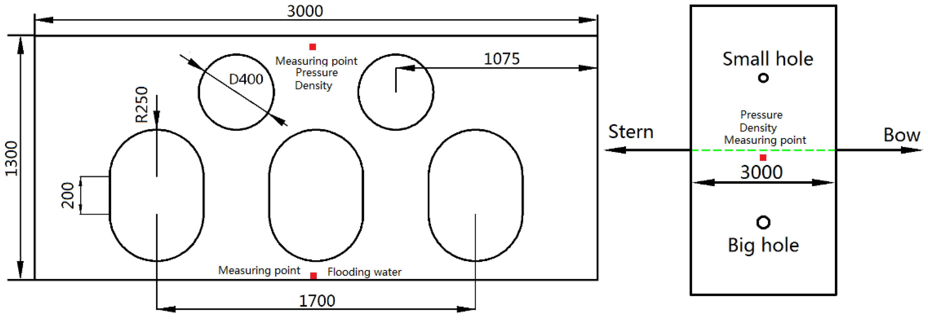
Figure 5, the flooded compartment is separated by a longitudinal bulkhead with openings. The diameter of the circular opening is 400 mm, and the size of the manhole is 500 mm × 700 mm, which are set according to the latest rules for the classification of seagoing steel ships. On the one hand, the compressed air flowed through bulkhead openings to the other side. On the other hand, the flooding water flowed to undamaged side, forming the symmetric flooding. It can also be seen from
Figure 4 that there are two ventilation holes on the upper deck of the flooded compartment. The small ventilation hole is on the port side with a diameter of 84 mm. The big ventilation hole is on the starboard side with a diameter of 120 mm. The size design of the ventilation holes is to verify a simplified assumption [
22] that the flooded compartment can be considered as fully ventilated if the total area of the ventilation holes is more than 10% of the damaged opening area. In this matter, there is no need to consider the effect of air compression on the flooding. The area of the small ventilation hole is 6% of the area of the damaged opening and the ratio for the big ventilation hole is 12%. The obtained simulation results are applied to validate the simplified assumption.
As shown in
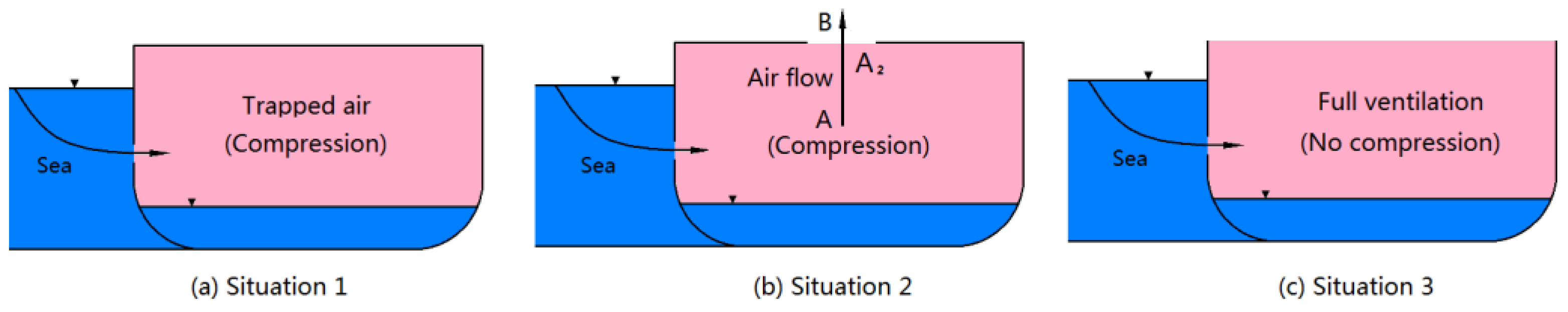
Table 3, five comparative flooding cases with different ventilation ratios are simulated separately. If the upper deck of the damaged compartment is closed (Case 1), the remaining compressed air inside the flooded compartment will be trapped. There will be final changes in the air pressure and density in the flooded compartment. In the event that there is a ventilation hole or several ventilation holes (Case 2, 3, and 4), compressed air will escape from the hole. The state of the air can be defined as vented air. In addition, Case 5 is the study of the situation of being fully ventilated, which is used to investigate the condition of no air compression.
3.2. Numerical Set Up
In the simulation process, the hull is considered to be a non-deformable rigid body, ignoring the longitudinal bending generated by uneven force. The computational model of the Euler multiphase flow under implicit unsteady is applied. The Euler multiphase flow model solves conservation equations for mass, momentum, and energy for each phase (air and water). Phase interaction models are provided to define the influence that one phase exerts upon another across the interfacial area between them. An implicit unsteady solver has been used to find the field of all hydrodynamic unknown quantities, in conjunction with an iterative solver to solve each time step. These inner iterations can be accomplished using implicit spatial integration or explicit spatial integration schemes. The integration scheme marches inner iterations using optimal pseudo-time steps that are determined from the Courant number. The simulation cases in this paper applied a constant physical time-step of 0.001 s, involving 10 inner iterations. In addition, the Reynolds stress is solved by means of the
k-ε turbulence model. It is a two-equation model in which transport equations are solved for the turbulent kinetic energy and its dissipation rate. In Begovic et al. [
23], it was reported that the numerical results from simulations with k-ω- and k-ε turbulence models are within 1.0% difference and it is not necessary to appreciate the difference between the two numerical curves.
After comprehensive consideration of previous research results [
23,
24] and the case of the KRISO Container Ship (KCS) with a rudder [
25], the appropriate boundary types and solver settings in this paper are concluded in
Table 4. By default, prism layers are not created for inlet, outlet, and symmetry boundaries. The entire computing region is arranged as shown in
Figure 6 with the bow pointing towards the inlet. Because the physical model of quasi-static water is applied, the magnitude of the flow velocity specified on the velocity inlet is zero and the setting of the inlet and outlet does not affect the simulation results. In order to simulate the flooding response of the ship in infinite water, the boundaries on the left and right sides are set to be symmetry planes, which can reduce the interference from the coupled motion of the ship and water. The free surface is modelled with the two phase VOF (Volume of Fluid) approach with a high-resolution interface capture scheme (HRIC) scheme based on the compressive interface capture scheme for arbitrary meshes introduced by Ubbink [
26] and developed by Muzeferija and Peric [
27]. This VOF approach is provided for systems containing two or more immiscible fluid phases, where each phase constitutes a large structure within the system (such as typical free surface flows). This approach captures the movement of the interface between air and water, and is often used for marine applications [
25]. Considering the movement of the ship, the ship’s 6-DOF (Degree of Freedom) are constrained to allow the ship to move vertically along the
Z-axis and rotate around the
X-axis. The sinking response due to additional flooding water was simulated by allowing the damaged ship to move along the
Z-axis, while the heel angle was recorded by monitoring the rotation around
X-axis. The specific coordinate axis is illustrated in
Figure 3.
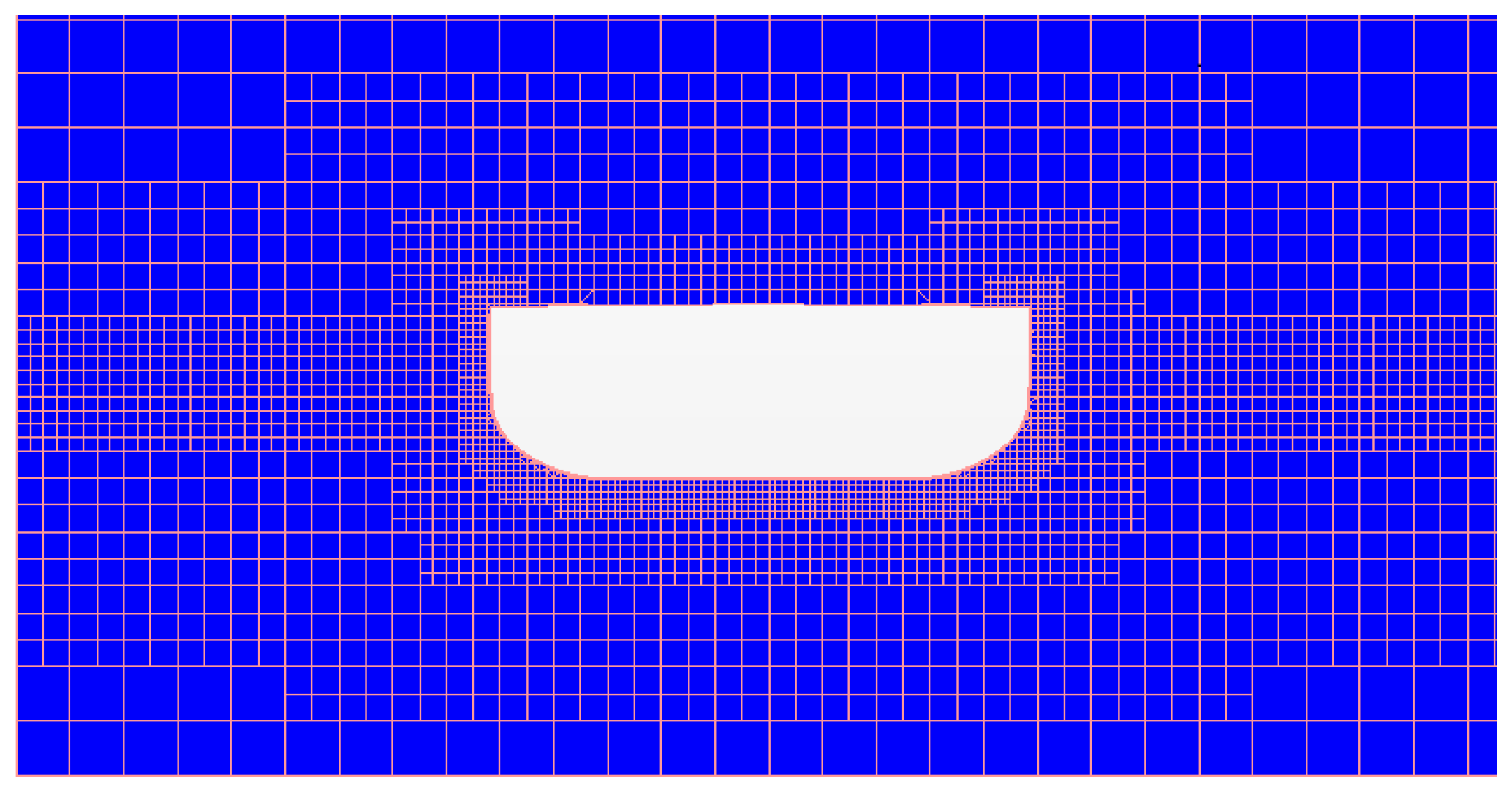
For the mesh generation, a trimmed mesh of hexahedral type is used, as shown in
Figure 7. The relevant sensitivity analysis was detailed in Begovic et al. [
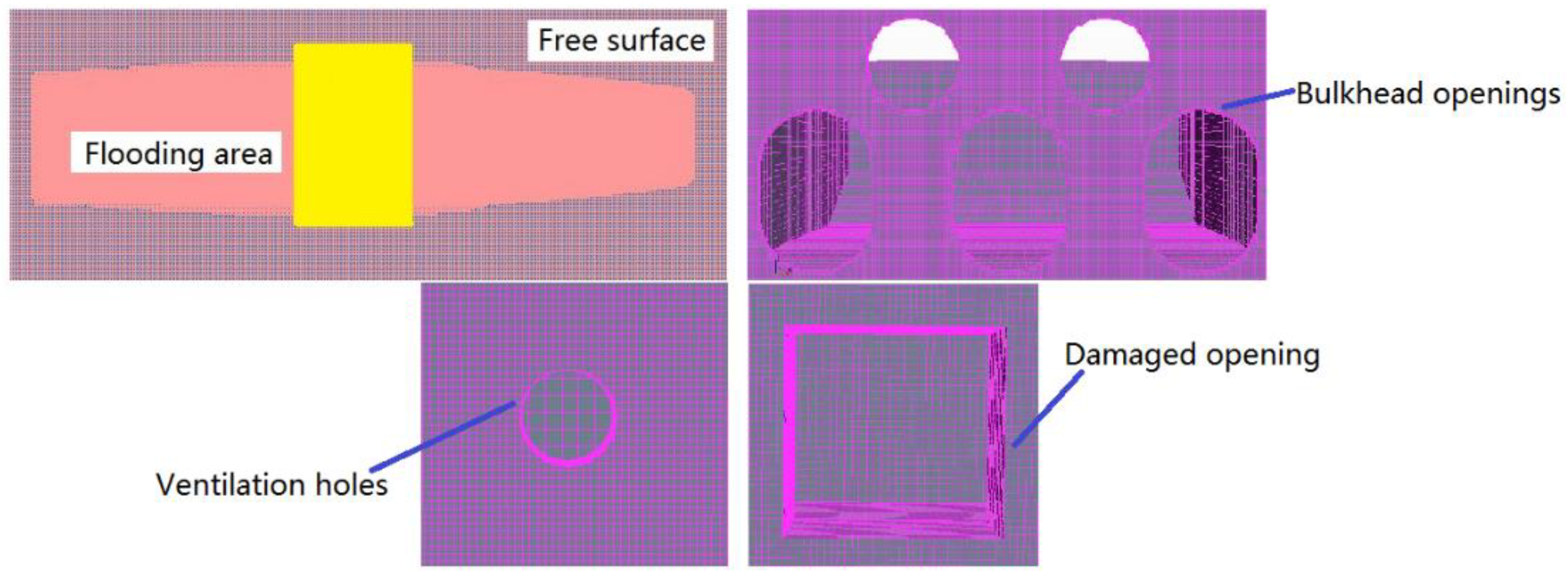
23]. Generally, the meshing generation is an important factor in determining the accuracy of the calculation. It should ensure that the surface shape of the hull cannot be distorted, especially for some locations where the curvature changes greatly or the surface has openings. For the simulations in this paper, there is a damaged opening on the starboard side of the ship, ventilation holes on the deck, and openings on the longitudinal bulkhead. If the same mesh size is applied as the hull, the shapes of theses openings will be distorted, so the mesh sizes in these places should be locally refined. As shown in
Figure 8, the shapes of the refined openings are almost the same as the original, thus the calculation results are reliable. In addition, the local volume mesh should be refined, which is also essential for improving the final accuracy. Here, the volume mesh of the free surface and the area of flooding are refined, which makes the mesh transition smoother and ensures convergence of the results. The specific mesh sizes in this paper are summarized as shown in
Table 5. The entire meshing process is based on the base size, which is about 1.0% to 1.5% of the ship’s length. The mesh sizes of other parts or regions are determined by taking the ratio relative to the base size.
During the simulations, several physical quantities in the damaged compartment are monitored, including: The gauge pressure relative to the environment pressure, the density, the height of flooding water, and the stability parameters (heel angle and heave displacement). In the applied numerical procedures, the air pressure, density, and flooding water are accounted for by measuring points in the damaged compartment. The specific coordinates are shown in
Table 2.
3.3. Simulation Results
3.3.1. Effect of the Ventilation Level
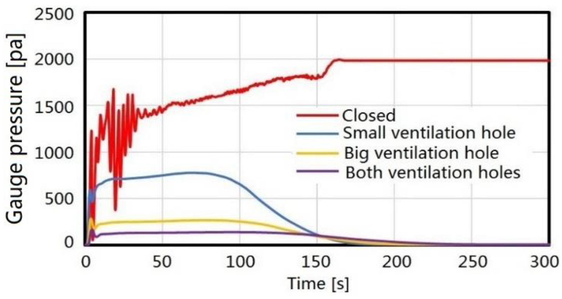
Four comparative cases are performed in order to assess the effect of the ventilation level on the air pressure in the flooded compartment. The monitored pressure, P, inside a flooded compartment is always taken as a gauge pressure relative to the environment pressure (101,325 Pa), because only the pressure differences are of importance to determine the air flux in the flooded compartment. This is determined by the algorithms built into the CFD software. As illustrated in
Figure 9, when the flooded compartment is closed, the air compression effect is significant, and the maximum gauge pressure is over 2 kPa. When only the small ventilation hole is open, the maximum gauge pressure is 850 Pa. When only the big ventilation hole is open, the maximum gauge pressure is reduced to only 280 Pa. When both ventilation holes are open, it is very similar to the full ventilation scenario, and the maximum gauge pressure is only 130 Pa. This fully demonstrates the conclusion that a limited ventilation level impedes the flow of compressed air, resulting in an increase of pressure. This compression phenomenon becomes more obvious as the area of the ventilation hole becomes smaller.
It can be found from the trend of the curves that the changing processes of the gauge pressure is affected by the flooding stages. The beginning of the damage flooding is called the transient stage. In this stage, there may be a significant fluctuation in the gauge pressure, which is related to the transient response of the ship. Especially for the closed case, when the ship rolls due to flooding water, part of the compressed air overflows from the damaged opening. This explains why the overpressure fluctuates even though there are no ventilation holes in the closed case. The damaged scenarios studied in this paper are like a collision. Even if the flooded compartment is closed, compressed air still has a limited overflow path. This is different from bottom stranding. When the flooding water enters the compartment from the bottom and the dissolution of air is ignored, there is no overflow path for the compressed air. All the compressed air is trapped.
With the increase of flooding water, the motion of the ship tends to be stable, and the gauge pressure increases gradually until it reaches equilibrium status. This process can be understood as a process from the progressing stage to a steady stage. For the closed case, some air is trapped, and the gauge pressure is maintained at a constant value. However, in the ventilation cases, compressed air always escapes. When the gauge pressure increases to its maximum, the value continuously decreases until it reaches zero.
3.3.2. Variation of Density
In order to clearly describe the air compression,
Figure 10 presents the changing processes of density. Four comparative cases were utilized to analyze the extent of air compression under different ventilation levels. For the ideal gas, if there is no air overflow during compression, the density is proportional to the pressure. As the pressure increases, so does the density. In the ventilation cases, the compressed air can escape from the ventilation hole, so the final density value stabilizes around the initial density. Considering the closed case, the compressed air is trapped in the remaining volume of the flooded compartment, and the final density is maintained at a constant value greater than the initial density. Although some compressed air escapes from the damaged opening, there is still a similar relationship between pressure and density. As shown in
Figure 9, for the closed case, the final gauge pressure stabilized at 2 kPa. Calculated by Equation (2), the final density should be as follows:
ρ = (101,325 + 2000)·1.1765/101,325 = 1.1997 kg/m
3. The theoretical calculation values fit the finally simulated density value of 1.20 kg/m
3 in the
Figure 10. For other cases with better ventilation levels, the extent of compression is much smaller than the small ventilation case, and the variation processes of the corresponding density are similar. In general, the changing processes satisfy the state equation of the ideal gas. Simultaneously, the consistency between the theoretical density value and the simulated density value validates the reliability of the CFD simulation and the convergence of the calculated results in this paper.
After analyzing the pressure and density,
Figure 11 shows the differences of flooding processes under different ventilation levels. For the entire flooding process, as the ventilation levels improve, the flooding progress becomes faster. It can also be seen that for the closed case, although there are no ventilation holes, there is still compressed air that overflows from the damaged opening. This explains why the final flooding height is only slightly different from other ventilation cases. Moreover, the compressed air in the closed compartment has a tendency to flow out, which causes the compressed air to impede the inflow of water and form a U-shape phenomenon near the opening. For the other two ventilation conditions, except for the flooding rate, the overall flooding process and the final flooding height are basically the same.
3.3.3. The Height of the Flooding Water
The water heights were converted by measuring the hydrostatic pressure at the same point. As shown
Figure 12, time domain comparisons were made for the water heights under different ventilation levels. The water heights are also affected by the flooding stage. Especially in the transient stage (about the first 50 s), the motion response of the ship is very complicated. The free surface in the flooded compartment is usually accompanied with sloshing, resulting in fluctuations of the height curves. With the ship motion tending to stabilize, the water height rises smoothly until it reaches equilibrium status, which can also be considered as a gradual process from the progressing stage to the steady stage. The specific ship motion response is described in
Section 3.3.4.
By analyzing the five different ventilation cases in
Figure 12, it can be found that the required time to reach the same flooding height is different. Also, as the ventilation level improves, the required time is less. Here, the effect of air compression on the flooding time is further investigated by comparing the closed case with the full ventilation case. As shown in
Figure 12, three water heights (0.6 m, 0.7 m, and 0.8 m) were selected for the analysis of the flooding time. When the water height of 0.6 m is reached, the closed case takes an additional 60 s longer than the full ventilation case. When the water height 0.7 m and 0.8 m, the extra time gradually increases (70 s, 85 s). This directly causes the different times to complete the flooding. These results fully demonstrate the delaying effect of air compression on flooding. In addition, the results obtained can be applied to validate the assumption made by IMO about complete ventilation. For the large ventilation levels and both ventilation levels, the ventilation ratios are 12% and 18%, respectively. Their flooding heights and flooding times are basically the same as the full ventilation scenario. At this time, the air compression in the flooded compartment has little effect on the flooding. In the small ventilation case, the ventilation ratio is only 6%. The final flooding time is about 30 s longer than the other ventilation cases. In this matter, the effect of air compression on the flooding cannot be ignored. In general, the comparison results satisfy the IMO assumption. In addition, some emphasis was placed on the final water height. In the ventilation cases, although the flooding time is different, the final water heights are consistent. However, due to the influence of some trapped air, the water height of the closed case is a little smaller than the ventilation cases. To a certain extent, a reduction of the flooding volume can improve the anti-sinking ability of ships.
Here, the estimation of the flooding time considering air compression was only studied through two connected compartments. The extra time between the closed case and full ventilation case was only dozens of seconds. If damage involves multiple compartments, the effect of air compression on flooding time is more significant. The extra time can even be several minutes. IMO under SOLAS Chapter III Regulation 21.1.4 requires that all survival craft are capable of being launched with their full complement of persons within a period of 30 min from the time the abandon ship signal is given. For a damaged ship, the available rescue time from the 30 min period is small due to the panic of the crew. So, the influence of air compression on the flooding time must be properly considered by obtaining a precise time estimation to ensure successful rescue operation.
3.3.4. Motion Responses of the Damaged Ship
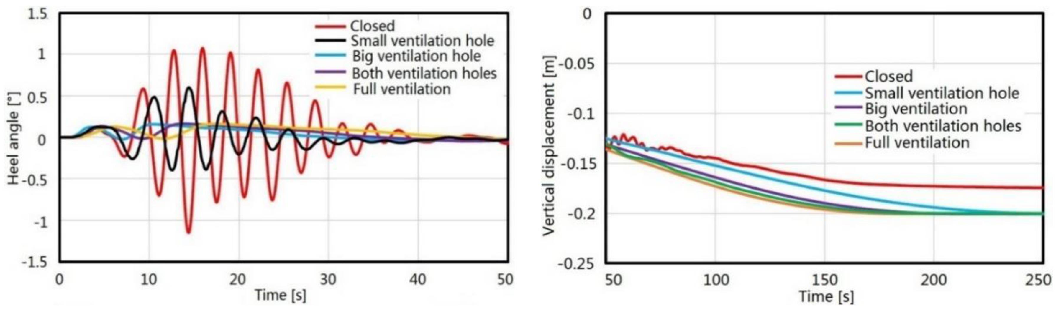
Through the above analysis, the characteristics of air compression and its influence on flooding were explained. However, the most significant point is to consider the effect of air compression on ship stability. In the simulations, the heel angle and heave displacement were monitored, reflecting the ship’s rolling damping and sinking status with different ventilation levels. In
Figure 13, the first 50 s of heel curves and heave curves after 50 s are illustrated. Through the overall analysis, it was found that the heel angles of all calculating cases were stable after the flooding continued for 50 s. However, it can be seen from the curves of the water heights that the flooding is in progress after 50 s. This is related to the form of flooding. The flooding form in this paper was a symmetric flooding, in which the flooding water can flow from the bulkhead holes to the other side. After the ship experienced the transient stage, the influence of the flooding water on the heel angle was very small. Therefore, in the primary design of the ship, the cross-flooding structures should be designed as much as possible to ensure that the damaged ship can maintain a balanced state in a short time.
Considering the magnitude of the heel angle, it can be seen that the closed ventilation case has a larger heel angle than the other ventilation cases. In the closed case, the maximum heel angle is 1.2°, which is twice the angle of the small ventilation case (0.6°) and six times the angles of the other ventilation cases (0.2°). For the large and both ventilation cases, the effect of air compression on the heel angle is small, almost the same as the full ventilation case. Similar comparisons were also made in the flooding height analysis. Although air compression causes a larger heel angle, the maximum heel angle of the closed case was only about one degree. This is because the symmetric flooding improves the stability of the damaged ship. If the flooding is asymmetric, even if the damaged compartment has a good ventilation level, the larger heel angle due to uneven force will pose a great threat to the safety of the ship. Pekka Ruponen et al. [
17] presented a series of full-scale experimental tests for the asymmetric flooding of a tank with a restricted ventilation level. The final value of the heel angle was about 2.5°, which is twice the maximum value (1.2°) of the symmetric flooding in this paper. After comparing the heel angle curves under different ventilation levels, it was found that when flooding occurs, the better the ventilation level, the smaller the heel angle, and the higher the stability. From this perspective, a symmetric flooding form with proper ventilation is critical to improving the stability of a damaged ship. This is because when the ventilation levels are adequate, the compression characteristics of the air will not adversely affect the flooding and the response of the ship, while due to the symmetric flooding, a damaged ship can gradually stabilize with a small heel amplitude.
Because the ship’s heel angle tends to be stable at about 50 s, the curves after 50 s are more representative for the analysis of vertical displacement. From the vertical displacement curves, it can be seen that the final vertical positions of the ship are the same for different ventilation cases. Because compressed air in the damaged compartment can escape through ventilation holes, different ventilation levels will affect the flooding time, but it has no effect on the final flooding volume and stable vertical displacement. In the closed case, the trapped air in the damaged compartment results in a certain reduction in the volume of the flooding water. This is similar to the analysis of the water heights. It can be seen clearly from
Figure 13 that the vertical displacement of the damaged ship in the closed case is smaller than the other cases. This also validates the basic conclusion that airtight compartments can improve the ship’s resistance to sinking. The obtained simulation results are satisfactory with the conclusion.
The described curves explain the damaged stability from two aspects, including the roll stability and heave motion. Especially for the closed case, it illustrates well the main influence of air compression. The relevant characteristics about the closed case are summarized as follows: First, due to the dynamics of compressed air, the ship’s heel angle is relatively larger than the ventilation cases. This is not recommended to improve ship stability; second, a closed compartment can reduce the volume of flooding water, which can effectively increase the ship’s anti-sinking ability. Combining these two characteristics, the suggestion given is that compartments with proper ventilation levels should be arranged inside the ship as much as possible, which can reduce the effect of air compression and slow down a ship’s sinking to a certain extent. However, the analysis and recommendations made are based on the assumption that the damaged ship will not capsize or sink due to damaged flooding. When damage occurs in more compartments, the ship will sink even if it is following the above suggestions of proper ventilation. In this case, no ventilation gives the possibility of floating, and the sinking time will take a long time even for the case of a sunk ship. Therefore, in future research, it is necessary that intelligent ventilation equipment is developed. If damage flooding occurs, the crew should firstly determine whether the ship may possibly sink. If the possibility of the ship sinking exists, the ventilation equipment can be used try to ensure that the compartments are airtight. Although it can cause a bad motion response, it can extend the floating time of the damaged ship and provide more convenience for rescue operations. Conversely, if the ship will not capsize, the ventilation ratio can be adjusted automatically to ensure a smooth motion response. The ventilation ratio is preferably controlled at around 10% based on the simulated results, which can greatly reduce the effect of air compression on the motion response. This is also satisfactory with the IMO assumption about complete ventilation.


