Article

Response Surface Analysis of Fenobucarb Removal by Electrochemically Generated Chlorine

Institute of Chemistry, Vietnam Academy of Science and Technology, 18 Hoang Quoc Viet, Cau Giay, Ha Noi 100000, Vietnam
*
Authors to whom correspondence should be addressed.
Water 2019, 11(5), 899; https://doi.org/10.3390/w11050899
Submission received: 22 March 2019 / Revised: 22 April 2019 / Accepted: 25 April 2019 / Published: 29 April 2019
(This article belongs to the Special Issue Water Disinfection: Safe Water for All)

Abstract

:
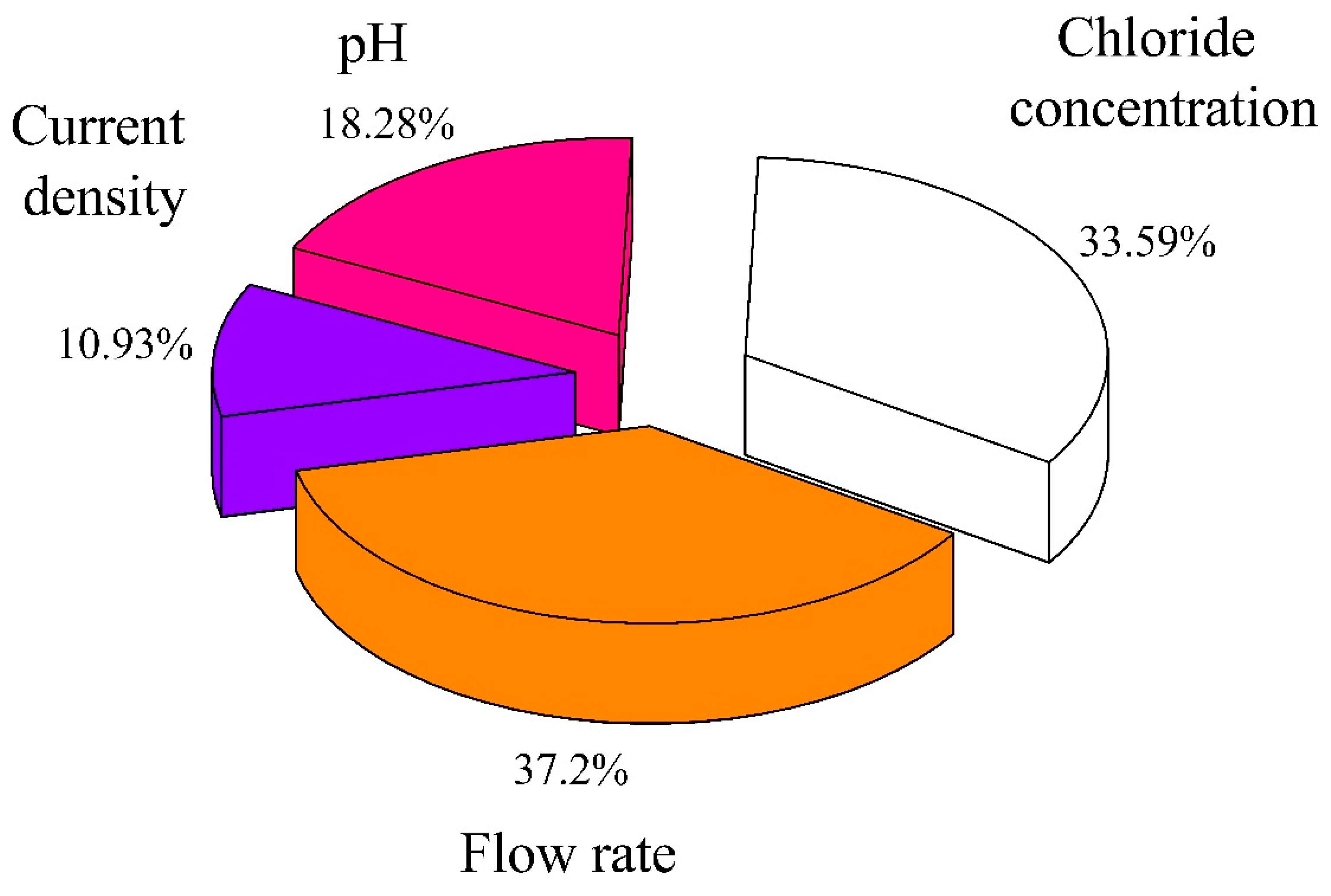
The aim of the present study was to investigate the electrochemical formation of active chlorine and its subsequent use for the degradation of the pesticide fenobucarb. Initially, the process of electrochemical active chlorine production was investigated using an electrochemical flow-cell with a Ti/RuO2 plate electrode. The contribution of four main factors (chloride concentration, current density, the retention time of chloride in the cell (flow rate), and initial pH of inlet solution) to form active chlorine was determined by a central composite design (CCD). The influence of the four variables was statistically significant, and the contributions of flow rate, chloride concentration, pH, and current density were found to be 37.2%, 33.59%, 18.28%, and 10.93%, respectively. A mathematical model was established to predict and optimize the operating conditions for fenobucarb removal in the NaCl electrolysis process. The main transformation products (seven compound structures) were detected by liquid chromatography coupled with high-resolution mass spectrometry (LC–HRMS). The results of the model and transformation products indicated that fenobucarb was degraded due to direct oxidation on the electrode surface, and indirectly by active chlorine and other radicals present during the NaCl electrolysis process.

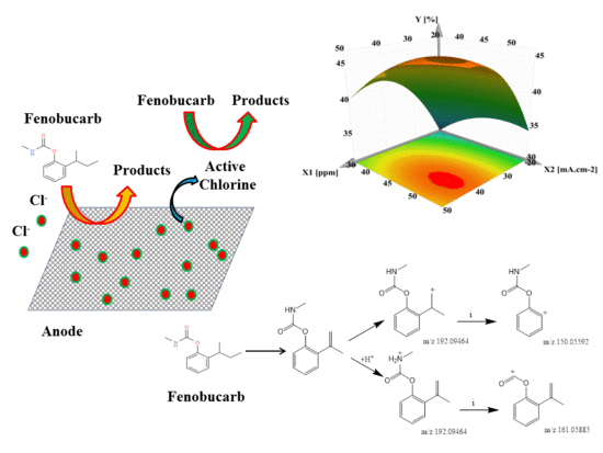
Graphical Abstract

1. Introduction

In recent decades, electrochemical-based systems for water treatment have received considerable attention [1,2]. Electrochemical technologies provide several advantages for the prevention and remediation of pollution problems because the electron is a clean reagent. Other advantages include high energy efficiency, amenability to automation, easy handling (because of the simple equipment required), safety (because they operate under mild conditions (room temperature and pressure)), and versatility (because they can be applied to effluents with chemical oxygen demands (COD) in the range of 0.1 to 100 g/L) [1,3]. The electrochemical method can treat organic compounds non-selectively by both direct and indirect mechanisms based on the activity of free radicals and strong oxidants formed in the electrolysis process. Interestingly, a number of studies have shown that the electrochemical generation of chlorine, and the subsequent formation of active chlorine (AC), are interesting alternatives for in situ degradation of pollutants [4,5,6]. AC is produced via the anodic formation of chlorine (Cl2) from the chloride ion (Cl) (Equation (1)).
2Cl → Cl2(aq) + 2e
Hypochlorous acid (HOCl) or hypochlorite (ClO) is formed from the dissolution of Cl2 in H2O. Hypochlorous acid is then in equilibrium with the hypochlorite ion at pKa = 7.55 (Equations (2) and (3))
Cl2(aq) + H2O(I) ↔ HClO(aq) + Cl(aq) + H+(aq)
HClO(aq) ↔ ClO(aq) + H+(aq)
The pollutants are degraded by direct interaction with the HClO, ClO species, other reactive species of oxygen or weaker oxidants generated from anodic oxidation of water. Pollutants can also be destroyed competitively by direct anodic oxidation.
In the electrochemical method, the production of strong oxidants depends on several main factors, such as electrode materials, electrolyte composition, current, pH, and temperature. One of the most important factors is the electrode material [7,8,9]. Currently, the types of electrodes used in the electrolytic process are divided into two types: The active electrode and the inactive electrode. PbO2, SnO2, and boron-doped diamond electrodes (BDD) [10], for example, are able to exchange electrons without chemically interacting with the oxidants generated. In contrast, active electrodes such as Pt-, IrO2-, and RuO2- are dimensionally stable anodes (DSAs) [10,11] which, in addition to performing the electron exchange process, have chemical interactions with oxidants. Because of the potential electrochemical activity of electrodes, it is necessary to select a suitable electrode material in each specific case [12]. In this study, AC was used as an oxidizing agent to treat organic compounds, so active electrodes such as Ti–RuO2 and Ti–IrO2 will be more effective [8,13].
Conversely, the formation of some by-products, such as ClO3 and ClO4, should not be considered greatly during electrolysis of chloride [3], as these products can seriously affect human health [14,15,16,17]. Some previous publications show that the level of formation of ClO3 and ClO4 when using Ti–IrO2 is higher than Ti–RuO2 in the NaCl electrolysis process [12,18]. Thus, Ti–RuO2 electrodes were selected for use in this study.
The optimization of a process is the objective of many studies. However, most processes have variables that influence each other, which is a difficultly when performing experiments. In such cases, the experimental design tool is extremely useful, as it helps to extract as much useful information as possible, with fewer experiments. Even though there are obvious advantages to the application of experimental design in the approach to electrochemical removal of pollutants, very few studies use the technique.
In this research, we aimed to: (i) Screen and investigate the use of response surface methodology (RSM) in order to evaluate the effects of operational parameters on AC formation in electrolysis; (ii) apply the RSM to evaluate the interactions of four independent variables (i.e., Cl, fenobucarb concentration, current density and flow rate (retention time of chloride in cell)), and the optimal conditions for the fenobucarb degradation process; and (iii) postulate the probable degradation pathways of fenobucarb under NaCl electrolysis by the liquid chromatography-tandem mass spectrometry (LC–MS/MS) methodology.

2. Materials and Methods

2.1. Materials

Sodium chloride (NaCl), sodium chlorite (NaClO2), sodium chlorate (NaClO3), sodium perchlorate (NaClO4), sodium nitrate (NaNO3), sodium sulfate (Na2SO4), sodium bicarbonate (NaHCO3), sodium carbonate (Na2CO3), potassium permanganate (KMnO4), sulfuric acid (H2SO4), phenol (C6H5OH), 2-(phenylethylhydrazono) propionic acid (PEHP, C11H14N2O2), sodium acetate (C2H3NaO2), DPD (N, N-diethyl-P-phenylenediamine, C10H10N2), and fenobucarb (C12H17NO2) were purchased from Sigma-Aldrich (St. Louis, Missouri, MO, USA). Phosphoric acid, methanol, and acetonitrile of high-performance liquid chromatography (HPLC) grade were obtained from Fisher Scientific (Waltham, MA, USA). Deionized water with resistance >18.2 MΩ was used for preparing samples and chemicals.

2.2. Electrochemical Equipment and Procedure

The electrochemical system is shown in Figure 1 and Figure S1. The undivided reactor cell and electrodes were produced by Adept Water Technology (Skovlunde, Denmark). The volume of the tank was 278 cm3, with the parameters as follows: Height 16.1 cm, width 1.5 cm, and length 11.5 cm. The current was supplied by the Adjustable Laboratory Power Velleman PS3020 (Belgian). Samples were pumped into the electrolysis cell by the Master Flex pump (USA). The Ti–RuO2 electrode was provided by Adept Company (Skovlunde, Denmark), and had an area of 54.94 cm2. Morphological characterization of the Ti–RuO2 electrode was carried out by scanning electron microscopy (SEM), as shown in Figure S2. The SEM images indicate quite a compact surface morphology composed of fine grains of cubic shape. The energy-dispersive X-ray (EDX) of the electrode is shown in Figure S3, Table S1. The EDX spectra shows an O peak at 0.477 KeV, Ru at 2.677 KeV, and Ti at 4.508 KeV, with the composition amount of 48.37 w%, 12.57 w%, and 31.79 w%, respectively.

2.3. Analysis of the Sample Solutions

The concentration of active chlorine was measured using the DPD (N, N-diethyl-p-phenylenediamine, C10H10N2) method with a U-2900 Ultraviolet–visible (UV/VIS) spectrophotometer 200V (Hitachi, Japan) at wavelength 515 nm according to ISO 7393-2:2017. ClO3, ClO4 and Cl were analyzed using ion chromatography (Metrohm) with a Metrosep A Supp 5 column, 100 × 4 mm, 61,006.510 and IC 819 detector. The injection volume was 20 µL and the eluent was Na2CO3 3.2 mM and NaHCO3 1.0 mM, while the flow rate was 0.7 mL min−1 [19]. H2SO4 2M was used as a suppressor solution. Samples were filtered by a 0.45 µm membrane before the ions were measured by ion chromatography.
Fenobucarb was detected at a wavelength of 215 nm by the HPLC–UV Thermo Scientific series 3300 HPLC system (Thermo Scientific Technologies, CA, USA), which was equipped with a G1311A Quart pump, a G1313A autosampler, a G1322A degasser, and a G1316A column oven. Chromatographic separation was performed using a Supelco C18 reverse-phase analytical column (2.1 × 250 mm; 5 μm particle size; Supelco, Milford, CT, USA) maintained at 30 °C. A binary mobile phase system, consisting of (A) methanol and (B) deionized water (70/30, v/v) was employed in the iso-cratic pump mode, with an injection volume of 20 μL.
The intermediates were identified by the liquid chromatography coupled with high-resolution mass spectrometry (LC–HRMS) Q-Exactive Focus system (Thermo). The MS/MS parameters were optimized as follows: Sheath gas flow rate: 35; aux gas flow rate: 15; sweep gas flow rate: 1; spray voltage (kV): 3.4; capillary temperature: 320 °C; S-lens radio frequency (RF) level: 50; aux gas heater temperature: 350 °C; and CE: 18. The mobile phase used included solvent (A) H2O 0.1% formic acid and solvent (B) CH3CN, with the gradient being 0 min: 5%B; 0–27 min: 5–95%B; 27–28 min: 95%B; 28–28.5 min: 5%B; and 28.5–30 min: 5%B. The signals were normally recorded in two modes, such as positive and negative, in 30 min.

2.4. Response Surface Methodology (RSM)

RSM is a useful tool for evaluating the influence of factors on the objective function [20]. A central composite design (CCD), a type of symmetrical second-order experimental design, was applied in this study. This design consists of the following parts (for four variables): A full factorial or fractional factorial design (number of experiment 16); an additional design, often a star design in which the experimental points are at a distance from the center (number of experiment 8); and a central point (number of experiment 7) [21]. MODDE 12.1 trial software was used to support the experimental design, statistical analyses, and optimization process.
Technically, the electrolytic efficiency of chloride depends on its retention time in the electrolytic device, and current density on the electrode. In this study, the retention time of chloride in the cell and the current density were converted into flow rate and current values, respectively, as shown in Table 1, for the purpose of changing parameters and designing the experiments easily.
Firstly, the RSM was used to evaluate the effect of four factors: Chloride concentration (X1), flow rate (X2), current density (X3), and initial pH (X4) on the form of active chlorine (Y1). The independent variables were investigated at five levels, and the real value was coded, as shown in Table 2.
Secondly, an electrochemical technique was investigated for fenobucarb degradation. The CCD was projected in order to fine-tune the efficiency of fenobucarb removal. Based on the screening experiments, four main factors affecting fenobucarb removal efficiency were: Chloride concentration (X’1), current density (X’2), flow rate (X’3) and initial fenobucarb (X’4). For optimum fenobucarb removal efficiency (Y2), the RSM was used with the experimental design of the CCD, which was four independent variables at five levels, as indicated in Table 3.

3. Results and Discussion

3.1. The Formation of AC and the Mass Balance during the NaCl Electrolysis Process

We know that chloride is transformed into active chlorine, chlorate, and perchlorate by an electrochemical and chemical reaction during the chloride electrolysis process. The mass balance process was studied to assess the loss of chloride due to the formation of Cl2 gas during electrolysis. As a result, the chloride concentration in the input and output solutions were determined. In addition, chlorate and perchlorate were measured in the output solution (converted into chloride content). The total chloride content before and after electrolysis was compared to assess the loss. The results showed that the total amount of chloride, active chlorine, and chlorate in the outlet solution (0.176 mM) was close to the chloride inlet solution (0.178 mM). However, some Cl2 gas escaped in the NaCl electrolysis process.

3.2. Effect of Initial Chloride Concentration, pH, Flow Rate, and Current Density

The formation mechanisms of active chlorine, chloride, chlorate, and perchlorate resulting from the electrochemical and chemical reactions in the electrolysis system are shown by Equations (1)–(17) (Table S2). The results of the experiments show that active chlorine formation depends on flow rate, current density, pH solution, and initial chloride concentration. From Figure 2a, the amount of chlorine formed clearly drops from 2.73 to 0.07 mg/L when the flow rate rises from 0.1 L/min to 1.0 L/min. An increase in flow rate leads to a decrease in the retention time of chloride in the electrolytic system (Table 1), and therefore the oxidation efficiency of the chloride at the anode decreases.
Figure 2b indicates that chloride concentration and current density influence active chlorine formation. At specific current density values, an increase in the concentration of the chloride inlet solution from 10 to 100 mg/L is associated with an increase in the amount of active chlorine (at current density 36.44 mA cm−2, the amount of active chlorine formed increases from 6.41 to 17.64 mg/L).
Thus, the influence of current density on the ability of chlorine formation is very clear. At chloride 10mg/L inlet solution, when the current density increases from 3.64 to 36.44 mA cm−2, the amount of active chlorine rises from 0.33 to 6.42 mg/L. The same variability was observed for other inlet solutions with varying chloride content.
This result may be explained by a change in the amount of electricity q (current density) and the conductivity of the solution (chloride concentration), as described in Fick’s law, Faraday’s law, and the Nernst equation [22].
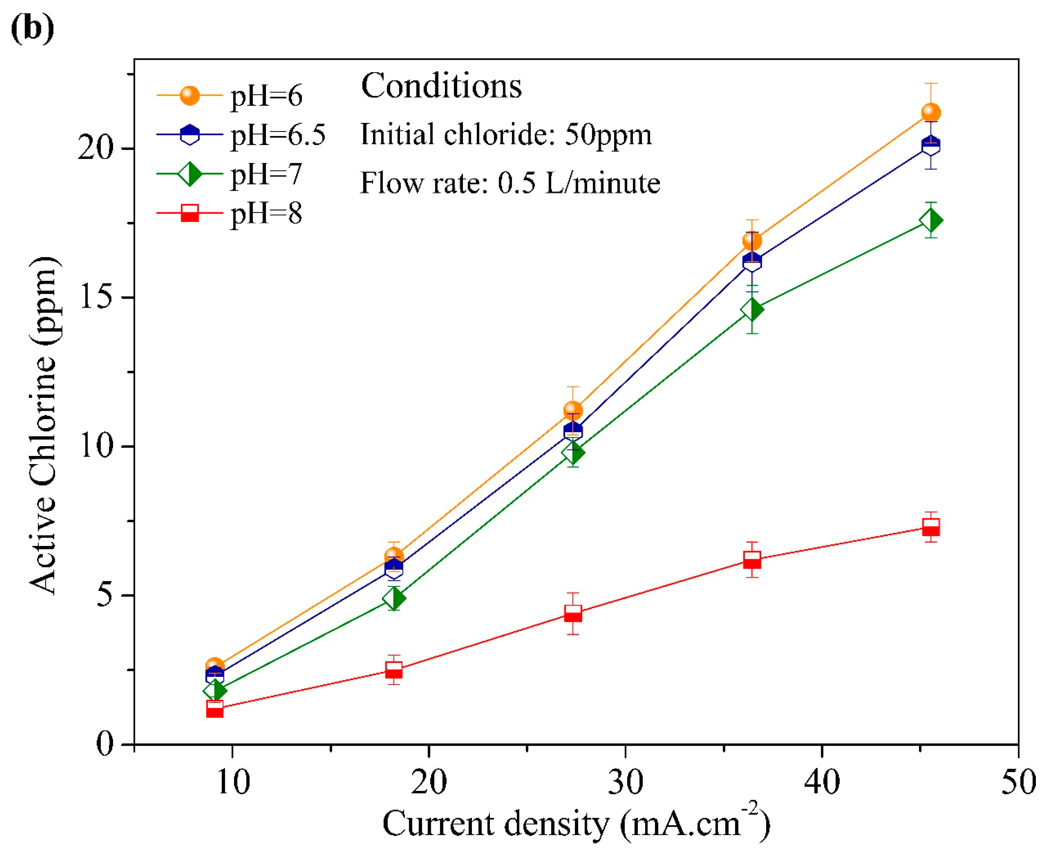
The results of the investigation on the effect of pH on the ability to form active chloride are shown in Figure 3. Clearly, increasing the initial pH from 6 to 8 by addition of PEHP and HCO3 led to a decrease in the ability to form active chloride, particularly for pH = 7–8. Presumably, there was a decrease in active chlorine when the pH was increased because of the formation of ClO2 and ClO3 [23,24]. This is indicated in Equations (5), (6), (8) and (17) (Table S2). In addition, when the pH was reduced from 7 to 6, active chlorine production increased slowly, as expected from the equilibrium described in Equations (18) and (19) (Table S2), with a shift in direction towards the left. This is observed as a reduction in the amount of active chlorine generated from chlorine during electrolysis.

3.3. Main Influence on the Formation of Active Chlorine during the Chloride Electrolysis Process

Active chlorine content is shown in Table S3, along with the different parameters of the four independent variables. The results obtained were used for statistical analysis and a determined regression equation using MODDE 12.1 trial software. The regression coefficient corresponding to the coding variable of the polynomial quadratic equation is shown in Table S4, and the P-value was used to evaluate the significance of the regression coefficients. Table S5 shows that the coefficient represented a linear interaction between the four independent variables, with the second order interaction between the two of the variables X1, X2 and X1, X4 being statistically significant (P-value < 0.05 at level confident 95%) on the formation active chlorine [25]. Noticeably, the significance of the linear regression coefficients was greater than interaction of the regression coefficients.
The regression equation obtained after removal of the insignificant coefficients (P-value > 0.05), and adjusts the values of the significant coefficients.
Y1 = 6.713 + 3.717 × 1 − 3.079 × 2 + 1.882 × 3 − 2.190 × 4 + 0.591 × 12 + 0.961 × 22 − 0.959 × 1 × 4
An analysis of variance (ANOVA) (Table S6) indicated that the significance of the model was expressed by the coefficient of determination (R2), coefficient of determination adjustment (R2-adj), P-value (lack of fit), and Fisher test (F-test). The values R2 and R2adj of the model were close to one, being 0.915 and 0.889, respectively, while the F calculated for the second order regression equation was 1.594 (<F (0.95, 17, 6) = 3874). This confirmed that the data of the experiment and the math model were good. The P-value of the lack of fit was 0.293 for Y1. An insignificant lack of fit (P > 0.05) was a desirable property because it would suggest that the model fit the data well. The three-dimensional response surface represents the interaction of the two factors and the factor contribution leading to the formation of active chlorine, as shown in Figure S4, Figure 4.
In summary, the results showed that chloride concentration and current density were proportional to AC formation, whereas the pH value of the inlet solution and the flow rate were inversely proportional to it. The influence of factors has been explained in Section 3.2. Furthermore, the results of the analysis by statistical algorithms showed that the percentage of contribution to chlorine content was 37.20%, 33.59%, 18.28%, and 10.93% for flow rate, chloride, pH, and current density, respectively. These values indicate that flow rate and chloride concentration are the two main factors affecting the ability of the active chlorine formation.

3.4. Application to Removal of Fenobucarb from Surface Water

Fenobucarb removal efficiency, which depended on different parameters of the four independent variants, is shown in Table S7. This was used for statistical analysis and regression equations. The regression coefficients (coding variable) of the polynomial quadratic equation are shown in Table 4. The P-value was used to evaluate the significance of the regression coefficients.
The results indicated that the four independent variables (chloride concentration, current intensity, flow rate, and fenobucarb concentration) had an effect on the removal efficiency of fenobucarb (P-value < 0.05). In addition, the second order interaction of chloride concentration, current density, and flow rate were found to be statistically significant (P-value < 0.05). Insignificant coefficients (P-value > 0.05) were removed to obtain a regression equation with the values of the significant coefficients only (Table S8).
Y2 = 44.672 + 4.679X’1 + 2.278X’2 − 9.074X’3 − 2.480X’4 − 5.546X’12 − 2.200 X’22 − 4.244X’32
Analysis of variance was used to evaluate the predicted regression equation in the experiment. According to Table 5, the coefficient of determination (R2) and the adjusted coefficient of determination (R2adj) for Y2 is 0.89 and 0.86, respectively. From these, the predictive power of the model may be considered relatively good (R2, R2adj > 0.80). Nevertheless, the R2 and R2adj values do not fully reflect the suitability of the model. Consequently, the lack of fit assessment and the use of the Fisher standard model were essential.
A lack of fit test evaluates the significance of the empirical data and the model’s predictive ability. If statistical testing was significant (P-value < 0.05), the model’s prediction would not be appropriate. The P-value (lack of fit) obtained—and presented in Table 5—was 0.201 (>0.05), giving an indication of the fit between the predicted and experimental results. The calculated F value of the model was 1.99 (<F (0.95, 17, 6) = 3.94), which also suggested that the regression model was able to predict results consistent with the empirical values.
In terms of the fenobucarb removal efficiency (FRE), the combined effect of two factors are notable from the 3D response face shown in Figure 5a and Figure S5. The results show that the four factors of chloride concentration, flow rate, current density, and fenobucarb concentration influence FRE in the water samples. In particular, two factors—flow rate and fenobucarb concentration—were found to be inversely proportional to the decomposition efficiency of fenobucarb. As the flow rate increases, it leads to a decrease in the retention time of components in the cell. In this case, the ability to remove fenobucarb decreases because fenobucarb gets oxidized directly on the surface electrode and indirectly by an AC decrease.
Both the current density and concentration of Cl, proportional to the fenobucarb removal efficiency, are related to active chlorine formation, which is perfectly consistent with the research results discussed in Section 3.2 and Section 3.3.
The influence of each factor is shown in Figure 5b, with the greatest contribution coming from fenobucarb concentration, with the influence of flow rate and chloride concentration being almost equal. Notably, the study results in Section 3.3 suggested that chloride had a large contribution to active chlorine formation (33.59%) in the electrolysis process, while only a small contribution in the decomposition process (6.48%). Moreover, the contribution of current density to fenobucarb degradation is 3.9 times larger than its contribution to AC formation. The above items have shown that in addition to decomposition by oxidizing agents, fenobucarb is directly oxidized on the electrodes, which is of great importance. The observed results are completely consistent with previous studies [26,27,28].
MODDE 12.1 trial software was used to optimize the conditions of fenobucarb treatment using electrolysis chloride. The most efficient fenobucarb removal was found to be 57.44% using chloride concentration 40.05 mg/L; current density 54.65 mA cm−2; flow rate 0.177 L/min (retention time of chloride: 94 s); and fenobucarb 1.0 mg/L. Moreover, the attained optimal conditions were tested in another experiment to validate the responses. The result demonstrated that 55.14% of fenobucarb in the solution was removed within 10 min. This confirmed that the model is reliable and accurate because of an increase in the fenobucarb removal efficiency from 54.57% to 57.44% (at a confidence level of 95%). Thence, the modeling result can serve to estimate the removal efficiency of fenobucarb with a high level of accuracy.

3.5. By-Products of Fenobucarb’s Degradation

Under experimental conditions, and according to the HPLC–UV data (Figure 6), the initial fenobucarb concentrations decreased over the electrolysis reaction time. This meant that the fenobucarb compound was decomposed and transformed into different compounds, including metabolites of fenobucarb [29]. However, the formed metabolites of fenobucarb were strongly dependent on the experimental conditions, such as Cl concentration, current intensity, and flow rate. The structure of the formed fenobucarb metabolites was accurately determined by ultra-high-performance liquid chromatography coupled with high-resolution mass spectrometry (UPLC–HRMS), which responds to mass errors of less than 5 mg/L. Moreover, in order to detect and identify the metabolites, the Compound Discoverer 2.1 (Thermo) program was used to detect the metabolite and recognize two identified fragments. The degradation pathways of fenobucarb under optimal experimental conditions may be summarized in Figure 7, including four possible pathways.
Generally, the structure of metabolites are unknown. Therefore, it is necessary to analyze the metabolite compounds in both positive and negative modes. At a neutral solution pH, two major identified metabolites were derived from the hydrolysis of fenobucarb. They were 2-(sec-butyl) phenol (2) (m/z = 151.11095; Figure S6) and methylcarbamic acid (3) (m/z = 76.03203; Figure S7). In addition, the compound (3) was decomposed to methylamine and carbon dioxide (Pathway 1, Figure 7). In aqueous solution, the carbamate compounds (i.e., fenobucarb) are often essential to the hydrolysis reaction and subsequent production of certain phenolic and carbamic compounds [30].
However, in the presence of free radicals (Cl and OH), compound (2) will consecutively react during hydroxylation. As a result, one new –OH group will appear in its benzene ring. Under the effect of Cl and OH, the bond between O and H (in the –OH group) is easily broken. Sequequenly, the electron transfer between O and the benzene ring results in (1) double bonds between O and the aromatic ring and (2) the formation of free radicals at the para position. The OH radical in solution attacks the para position of the benzene ring to form a new –OH group (Pathway 2, Figure 7). This group is dehydrated to form the dione compound 2-(sec-butyl) cyclohexane-2,5-diene-1,4 –dione (5) m/z = 165.08373; Figure S8.
For Pathway 3, the formation of (4) compound 2-(prop-1-en-2-yl) phenyl methylcarbamate, (m/z = 192.09464; Figure S9) results in de-alkylation and dehydration reactions of fenobucarb. The reactions may be described as follows: (1) Free Cl radicals in the solution are attacked by the alkyl group of fenobucarb to form a free organic radical; (2) free OH radicals in the solution are attacked by the free-formed organic radicals to form an alcoholic compound; and (3) the alcoholic compound is dehydrated to form an alkene compound. Lastly, some unknown compounds of fenobucarb degradation include (6) (m/z = 102.97379) and a monochloride compound (7) (m/z = 82.95235). This is because of their small molecular weights and insufficient fragmentation data.

4. Conclusions

From this work, the following conclusions can be drawn:
  • Factors influencing active chlorine formation have been shown, with four main factors: Chloride content, electric current, flow rate (retention time of Cl- ion), and initial pH.
  • The contribution percentage of the four main factors were indicated by RSM, in which the factors were arranged in the direction of diminishing influence: Flow rate > chloride concentration > pH > current density.
  • RSM was used to assess the interaction of four independent variables in the process of eliminating fenobucarb. The results showed that the ability to remove fenobucarb was greatest under the experimental conditions of chloride concentration 40.05 mg/L; current density 54.65 mA·cm−2; flow rate 0.177 L/min (retention time 94.4 s); and fenobucarb 1.0 mg/L.
  • Seven metabolites were detected by LC–MS/MS in combination with Compound Discoverer 2.1. The decomposition of fenobucarb occurs via four pathways: Hydrolysis of fenobucarb, oxidation by Cl, OH free radicals, and the direct oxidation of fenobucarb at the electrode surface.

Supplementary Materials

The following are available online at https://www.mdpi.com/2073-4441/11/5/899/s1, Figure S1. The electrochemical system of Adept Water Technology, Figure S2. SEM image of electrode, Figure S3. EDX spectra analyst of Ti-RuO2 electrode, Figure S4. Three-dimensional response surface for active chloride formation, Figure S5. Three-dimensional response surface for fenobucarb removal efficiency, Figure S6. 2-(sec-butyl) phenol and fragmentation, Figure S7. Methylcarbamic and fragmentation, Figure S8. 2-(sec-butyl) cyclohexane-2,5-diene-1,4 –dione fragmentation, Figure S9. 2-(prop-1-en-2-yl) phenyl methylcarbamate fragmentation; Table S1. Components percentage of elements, Table S2. Reactions at electrode and solution, Table S3. Experiments matrix and results for model Y1, Table S4. Regression coefficient of model Y1, Table S5. Coefficient adjustment of model Y1, Table S6. Analysis of variance Y1, Table S7. Experiments matrix and results of Y2, Table S8. Coefficient adjustment of Y2.

Author Contributions

Y.H.D., G.T.L. contributed substantially to the design of the study, the analyses, validation, and interpretation of experimental data, and the original draft preparation. Y.H.D. and T.Q.P. analysed and verified the experimental data, made the figures, and wrote the manuscript. T.Q.P., N.T.T. designed and took responsibility for the response surface methodology. G.T.L. contributed to the supervision, conceptualization, validation, project administration. All authors have read and approved the submission.

Funding

This research was financially supported by National Foundation for Science and Technology Development (NAFOSTED) (the grant number: 104.06-2013.54).

Acknowledgments

The authors would like to thank the National Foundation for Science and Technology Development for financial support.

Conflicts of Interest

The authors declare no conflicts of interest.

References

  1. Vasudevan, S.; Oturan, M.A. Electrochemistry: As cause and cure in water pollution—An overview. Environ. Chem. Lett. 2013, 12, 97–108. [Google Scholar] [CrossRef]
  2. Brillas, E.; Martínez-Huitle, C.A. Decontamination of wastewaters containing synthetic organic dyes by electrochemical methods. An updated review. Appl. Catal. B Environ. 2015, 166–167, 603–643. [Google Scholar] [CrossRef]
  3. Bergmann, M.E.H.; Koparal, A.S.; Iourtchouk, T. Electrochemical Advanced Oxidation Processes, Formation of Halogenate and Perhalogenate Species: A Critical Review. Crit. Rev. Environ. Sci. Technol. 2014, 44, 348–390. [Google Scholar] [CrossRef]
  4. Vos, J.G.; Koper, M.T.M. Measurement of competition between oxygen evolution and chlorine evolution using rotating ring-disk electrode voltammetry. J. Electroanal. Chem. 2018, 819, 260–268. [Google Scholar] [CrossRef]
  5. Pinto, C.F.; Antonelli, R.; de Araujo, K.S.; Fornazari, A.L.T.; Fernandes, D.M.; Granato, A.C.; Azevedo, E.B.; Malpass, G.R.P. Experimental-design-guided approach for the removal of atrazine by sono-electrochemical-UV-chlorine techniques. Environ. Technol. 2017, 40, 430–440. [Google Scholar] [CrossRef] [PubMed]
  6. Moreira, F.C.; Boaventura, R.A.R.; Brillas, E.; Vilar, V.J.P. Electrochemical advanced oxidation processes: A review on their application to synthetic and real wastewaters. Appl. Catal. B Environ. 2017, 202, 217–261. [Google Scholar] [CrossRef]
  7. Jeong, J.; Kim, C.; Yoon, J. The effect of electrode material on the generation of oxidants and microbial inactivation in the electrochemical disinfection processes. Water Res. 2009, 43, 895–901. [Google Scholar] [CrossRef] [PubMed]
  8. Ming, R.; Zhu, Y.; Deng, L.; Zhang, A.; Wang, J.; Han, Y.; Chai, B.; Ren, Z. Effect of electrode material and electrolysis process on the preparation of electrolyzed oxidizing water. New J. Chem. 2018, 42, 12143–12151. [Google Scholar] [CrossRef]
  9. Song, X.; Zhao, H.; Fang, K.; Lou, Y.; Liu, Z.; Liu, C.; Ren, Z.; Zhou, X.; Fang, H.; Zhu, Y. Effect of platinum electrode materials and electrolysis processes on the preparation of acidic electrolyzed oxidizing water and slightly acidic electrolyzed water. RSC Adv. 2019, 9, 3113–3119. [Google Scholar] [CrossRef]
  10. Canizares, P.; Martınez, F.; Dıaz, M.; Garcıa-Gómez, J.; Rodrigo, M.A. Electrochemical oxidation of aqueous phenol wastes using active and nonactive electrodes. Electrochem. Soc. 2002, 149, 118–124. [Google Scholar] [CrossRef]
  11. Jiang, M.; Wang, H.; Li, Y.; Zhang, H.; Zhang, G.; Lu, Z.; Sun, X.; Jiang, L. Superaerophobic RuO2 -Based Nanostructured Electrode for High-Performance Chlorine Evolution Reaction. Small 2017, 13, 1602240. [Google Scholar] [CrossRef]
  12. Patel, P.S.; Bandre, N.; Saraf, A.; Ruparelia, J.P. Electro-catalytic Materials (Electrode Materials) in Electrochemical Wastewater Treatment. Procedia Eng. 2013, 51, 430–435. [Google Scholar] [CrossRef] [Green Version]
  13. Luu, T.L.; Kim, C.; Kim, S.; Kim, J.; Yoon, J. Fabricating macroporous RuO2-TiO2 electrodes using polystyrene templates for high chlorine evolution efficiencies. Desalin. Water Treat. 2017, 77, 94–104. [Google Scholar] [CrossRef]
  14. Urbansky, E.T.; Schock, M.R. Issues in managing the risks associated with perchlorate in drinking water. J. Environ. Manag. 1999, 56, 79–95. [Google Scholar] [CrossRef]
  15. Srinivasan, R.; Sorial, G.A. Treatment of perchlorate in drinking water: A critical review. Sep. Purif. Technol. 2009, 69, 7–21. [Google Scholar] [CrossRef]
  16. Siddiqui, M.S. Chlorine-ozone interactions: Formation of chlorate. Water Res. 1996, 30, 2160–2170. [Google Scholar] [CrossRef]
  17. Richardson, S.D.; Plewa, M.J.; Wagner, E.D.; Schoeny, R.; DeMarini, D.M. Occurrence, genotoxicity, and carcinogenicity of regulated and emerging disinfection byproducts in drinking water: A review and roadmap for research. Mutat. Res. 2007, 636, 178–242. [Google Scholar] [CrossRef]
  18. Yoon, Y.; Cho, E.; Jung, Y.; Kwon, M.; Yoon, J.; Kang, J.W. Evaluation of the formation of oxidants and by-products using Pt/Ti, RuO2/Ti, and IrO2/Ti electrodes in the electrochemical process. Environ. Technol. 2015, 36, 317–326. [Google Scholar] [CrossRef]
  19. Michalski, B.M. The occurrence of Chlorite, Chlorate, and Bromate in Disinfected Swimming Pool Water. Pol. J. Environ. 2007, 16, 237–241. [Google Scholar]
  20. Khuri, A.I.; Mukhopadhyay, S. Response surface methodology. Wiley Interdiscip. Rev. Comput. Stat. 2010, 2, 128–149. [Google Scholar] [CrossRef] [Green Version]
  21. Bezerra, M.A.; Santelli, R.E.; Oliveira, E.P.; Villar, L.S.; Escaleira, L.A. Response surface methodology (RSM) as a tool for optimization in analytical chemistry. Talanta 2008, 76, 965–977. [Google Scholar] [CrossRef]
  22. Hsu, G.W.; Lu, Y.F.; Hsu, S.Y. Effects of electrolysis time and electric potential on chlorine generation of electrolyzed deep ocean water. J. Food Drug Anal. 2017, 25, 759–765. [Google Scholar] [CrossRef]
  23. Ciblak, A.; Mao, X.; Padilla, I.; Vesper, D.; Alshawabkeh, I.; Alshawabkeh, A.N. Electrode effects on temporal changes in electrolyte pH and redox potential for water treatment. J. Environ. Sci. Health Part A 2012, 47, 718–726. [Google Scholar] [CrossRef] [Green Version]
  24. Jung, Y.J.; Baek, K.W.; Oh, B.S.; Kang, J.W. An investigation of the formation of chlorate and perchlorate during electrolysis using Pt/Ti electrodes: The effects of pH and reactive oxygen species and the results of kinetic studies. Water Res. 2010, 44, 5345–5355. [Google Scholar] [CrossRef]
  25. Greenland, S.; Senn, S.J.; Rothman, K.J.; Carlin, J.B.; Poole, C.; Goodman, S.N.; Altman, D.G. Statistical tests, P values, confidence intervals, and power: A guide to misinterpretations. Eur. J. Epidemiol. 2016, 31, 337–350. [Google Scholar] [CrossRef]
  26. Wu, W.; Huang, Z.-H.; Lim, T.-T. Recent development of mixed metal oxide anodes for electrochemical oxidation of organic pollutants in water. Appl. Catal. A Gen. 2014, 480, 58–78. [Google Scholar] [CrossRef]
  27. Wang, L.; Wu, B.; Li, P.; Zhang, B.; Balasubramanian, N.; Zhao, Y. Kinetics for electro-oxidation of organic pollutants by using a packed-bed electrode reactor (PBER). Chem. Eng. J. 2016, 284, 240–246. [Google Scholar] [CrossRef]
  28. Song, H.-L.; Zhu, Y.; Li, J. Electron transfer mechanisms, characteristics and applications of biological cathode microbial fuel cells—A mini review. Arab. J. Chem. 2015, in press. [Google Scholar] [CrossRef]
  29. Wang, Q.; Lemley, A.T. Competitive Degradation and Detoxification of Carbamate Insecticides by Membrane Anodic Fenton Treatment. J. Agric. Food Chem. 2003, 51, 5382–5390. [Google Scholar] [CrossRef]
  30. Roberts, T.R.; Hutson, D.H. Phenyl carbamates. In Metabolic Pathways of Agrochemicals: Part 2: Insecticides and Fungicides; Roberts, T.R., Hutson, D.H., Eds.; The Royal Society of Chemistry: Cambridge, UK, 1999; pp. 1283–1288. [Google Scholar]
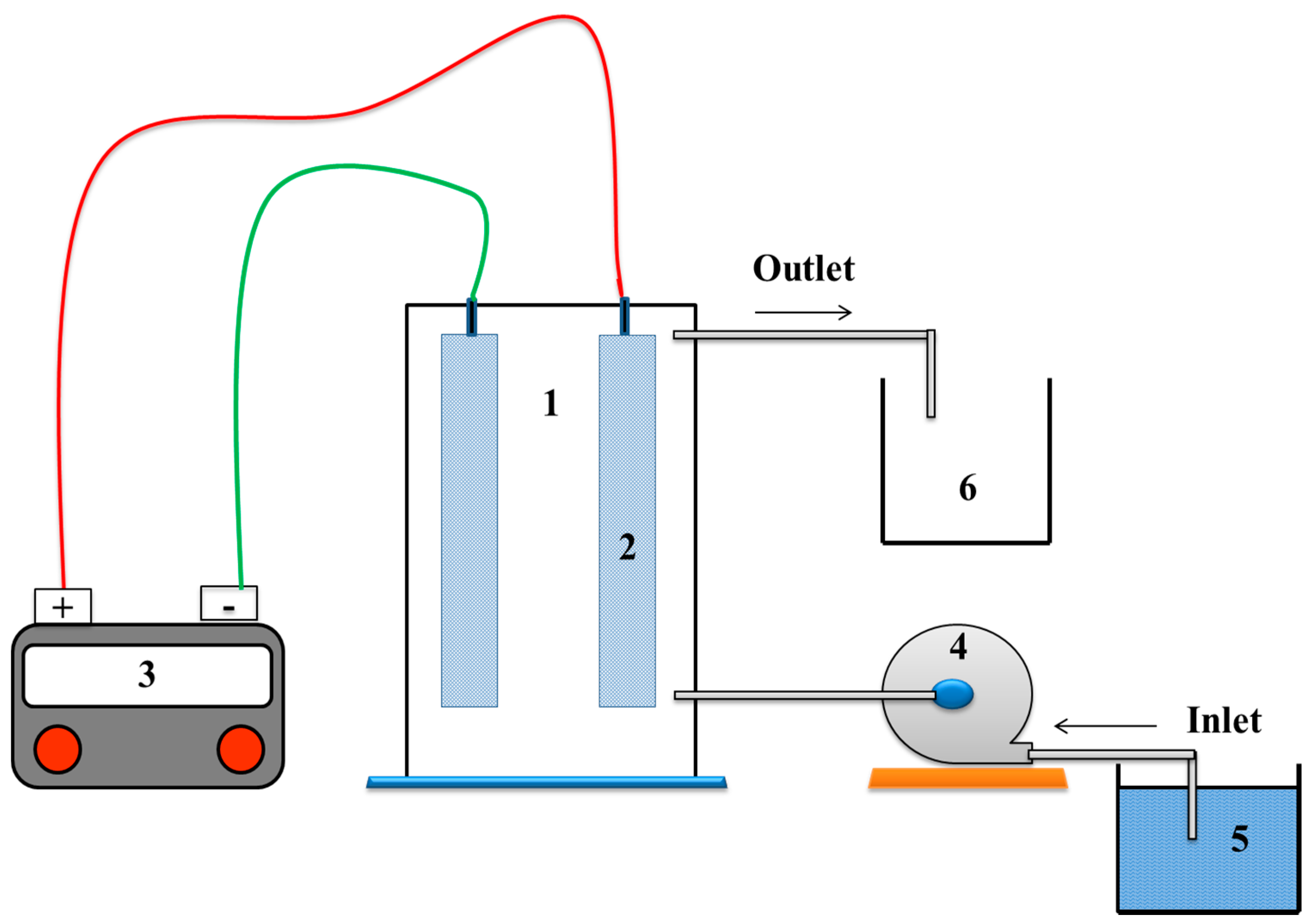
Figure 1. The electrochemical system: 1- Electrolysis cell, 2- Electrode, 3- Adjustable DC power supply, 4- Peristaltic pump, 5- Inlet reservoir, and 6- Outlet reservoir.
Water 11 00899 g001
Figure 2. (a) The formation of active chlorine as a function of flow rate. (b) The formation of active chlorine as a function of electrode current at four different initial chloride concentrations.
Water 11 00899 g002
Figure 3. Effect of pH on the formation of active chlorine. The pH of the inlet solution is adjusted by addition of (a) 2-(phenylethylhydrazono) propionic acid (PEHP), and (b) HCO3.
Water 11 00899 g003aWater 11 00899 g003b
Figure 4. The percent factor contributing to the formation of active chlorine.
Water 11 00899 g004
Figure 5. (a) Three-dimensional response surface representing the influence (X1’: chloride concentraion; X2’: current density) and; (b) percent factor contribution to removal efficiency of fenobucarb.
Water 11 00899 g005aWater 11 00899 g005b
Figure 6. Fenobucarb decreases with time.
Water 11 00899 g006
Figure 7. Possible pathways of fenobucarb degradation under electrolysis NaCl.
Water 11 00899 g007
Table 1. Value conversion.
Flow Rate (L/min)Retention Time (s)Current (A)Current Density (mA cm−2)
0.11670.23.64
0.2830.59.11
0.3561.018.22
0.4421.527.33
0.5332.036.44
0.6282.545.55
0.8213.054.66
1.0173.563.77
Table 2. Parameter and level independent variables for active chlorine (AC) formation.
SymbolVariableCoded Variable and Independent Variables
−α−10+1
X1Chloride concentration (mg/L)1030507090
X2Flow rate (L/min)0.10.20.30.40.5
X3Current density (mA cm−2)9.1118.2227.3336.4445.55
X4pH56789
Table 3. Independent variables for fenobucarb removal efficiency.
SymbolVariableCoded Variable and Independent Variables
−α−10+1
X’1Chloride concentration (mg/L)520355065
X’2Current density (mA cm−2)27.3333.6445.5554.6663.77
X’3Flow rate (L/min)0.10.20.30.40.5
X’4Fenobucarb concentration (mg/L)0.51.01.52.02.5
Table 4. The regression coefficient for Y2.
Y2Coeff. SCStd. Err.PConf. int (±)
b’045.47141.90025.92352 × 10−144.0282
b’14.67881.02620.0003217082.1755
b’22.27791.02620.04123742.1755
b’3−9.07381.02621.47924 × 10−72.1755
b’4−2.47961.02620.02799972.1755
b’11−5.62940.94011.89544 × 10−51.9930
b’22−2.28320.94010.0273211.9930
b’33−4.32690.94010.0002943191.9930
b’44−0.78320.94010.417091.9930
b’12−0.15441.25690.9037782.6644
b’13−0.49811.25690.6971022.6644
b’140.04941.25690.969152.6644
b’23−1.52061.25690.2439062.6644
b’24−0.86811.25690.4996482.6644
b’341.50061.25690.2499012.6644
N = 31Q2 = 0.570Cond. no. = 4.686
DF = 16R2 = 0.913RSD = 5.027
R2 adj = 0.836
Notes: DF = degree of freedom; RSD = relative standard deviation; Std. Err. = standard error; Conf. int (±) = confidence interval; P = probability; Cond.no. = condition no. experiments.
Table 5. The result ANOVA of model Y2.
Y2DFSSMS (variance)FpSD
Total3143,453.91401.7
Constant138,824.638824.6
Total corrected304629.3154.3 12.4222
Regression74117.9588.326.45640.00024.2543
Residual23511.422.2 4.71546
Lack of Fit17434.525.61.993390.2015.05551
Pure error676.912.8 3.58071
N = 31Q2 = 0.726Cond. no. = 3.783
DF = 23R2 = 0.890RSD = 4.715
R2 adj = 0.856
Notes: SS = sum of squares; MS = mean square; F = Fisher calculate; SD = standard deviation; Cond.no. = condition no. experiments.