Article

Classification of Management Alternatives to Combat Reservoir Sedimentation

by
Gregory L. Morris
GLM Engineering PSC, San Juan, PR 00907, USA
Water 2020, 12(3), 861; https://doi.org/10.3390/w12030861
Submission received: 9 January 2020 / Revised: 11 March 2020 / Accepted: 13 March 2020 / Published: 19 March 2020
(This article belongs to the Special Issue Reservoir Sustainability: Engineering, Economics, and Ecosystems)

Abstract

:
Sedimentation is steadily depleting reservoir capacity worldwide, threatening the reliability of water supplies, flood control, hydropower energy and other benefits that form the basis of today’s water-intensive society. The strategies available to combat reservoir sedimentation may be classed into four broad categories. Three proactive categories seek to improve the sediment balance across reservoirs by: (a) reducing sediment yield from the watershed, (b) routing sediment-laden flows around or through the storage pool, and (c) removing deposited sediment following deposition. The fourth category (d) consists of strategies that adapt to capacity loss, without addressing the sediment balance. Successful management will typically combine multiple strategies. This paper presents a comprehensive classification of both proactive and adaptive strategies, consistent with current international practice. Functional descriptions and examples are given for each strategy, and criteria are provided to differentiate between them when there is potential for ambiguity. The classification categories can be used as a checklist of strategies to consider in evaluating sediment management alternatives for new designs as well as remedial work at existing sediment-challenged reservoirs. This will also help practitioners to more clearly describe and communicate the nature of their management activities. Widespread application of both active and adaptive strategies is required to bring sedimentation under control to sustain benefits of water storage for today’s and future generations.

1. Introduction

Dam construction creates a quiescent pool that interrupts the transport of sediment to the ocean. Reservoirs have already trapped more than 100 billion metric tons of sediment, representing 26% of the global sediment delivery to the ocean [1]. In regulated basins, more than 50% of the sediment flux may be trapped. In highly developed river basins such as the Colorado and the Nile virtually all sediment is trapped in reservoirs [2].
Progressive sedimentation together with a low rate of new reservoir construction has resulted in a declining reservoir storage volumes, and when population growth is factored in the per capita storage is declining rapidly [3]. For example, per capita reservoir storage in the USA peaked at 45,000 m3/capita in 1975, but by 2019 had declined to 27,000 m3/capita, a 40% reduction [4]. Total global capacity peaked around 2006, and global per capacity has been in decline since the 1980s [5]. Without effective action many reservoirs will see their function substantially impaired by sedimentation before reaching 100 years of age. For example, India’s Central Water Commission [6] published survey data from 243 large reservoirs—of which, 141 had been impounding for at least 50 years. In this group, 25% had already lost more than 30% of their original capacity. At 50 sites for which design sedimentation rates were given, 63% of the sites (representing 45% of the storage volume) were experiencing volume loss rates more than double the predicted rate.
Declining reservoir capacity directly threatens our ability to provide reliable water supplies for both agricultural and urban use, and also interferes with other uses including flood control, hydropower, navigation and fisheries [7]. The impacts of sediment trapping are not limited to reservoirs, but also extend downstream to the coastline. River channels deprived of their sediment load, and particularly the load of coarse material that helps define channel morphology, can be heavily impacted by channel incision, dewatering of riparian areas, accelerated bank erosion, and habitat loss [8]. Sediment trapping in reservoirs, together with in-channel mining [9], impact the fluvial sediment balance and even contribute to coastal erosion [10,11].
Because erosion will never stop, and reservoir capacity is limited, sediment trapping is only a transitory phenomenon. The equilibrium between sediment inflow and outflow will be restored after the reservoir becomes filled and storage benefits are lost, or it may be achieved while sustaining reservoir functions through sediment management actions. To sustain long-term reservoir capacity is a management decision (Figure 1). Despite knowledge of sediment management alternatives for reservoirs prior to the dam construction boom that began in the 1950s [12,13], nearly all reservoirs worldwide have been designed on the basis of the “life of reservoir” paradigm. Sediment inflows have been calculated using a 50 to 100 year planning horizon and the corresponding sediment storage volume allocated in the storage pool. No consideration was given to sedimentation consequences beyond this planning horizon. Reservoir design and operation without a long-term sediment management strategy is not a sustainable approach, and no longer represents an engineering best-practice.
Most civil and hydraulic infrastructure such as highways, buildings and mechanical systems can be replaced or reconstructed after they have aged. However, dams cannot be reconstructed to serve their intended purpose once the storage pool becomes sedimented because the removal of large sediment volumes is rarely economically feasible. Sites suitable for new dam and reservoir construction are limited by topography, geology, hydrology, and competing land uses. Today’s reservoirs already occupy the best sites and represent a unique and limited resource [7,14].
Today, we have an inventory of aging reservoirs with steadily growing sedimentation problems. This underscores the need to analyze the sedimentation status and management potential for all reservoirs, and to begin aggressive implementation of technologies to sustain reservoir function [15]. Given the importance of today’s reservoirs in sustaining our society, and the impossibility of simply replacing today’s inventory of dams with new construction, Morris and Fan [14] noted, “Whereas the twentieth century focused on the construction of new dams, the twenty-first century will necessarily focus on combating sedimentation to extend the life of existing infrastructure. The task will be greatly facilitated if we start today.
Reservoir function cannot be sustained without implementing a sediment management plan. This paper outlines strategies available for managing reservoir sedimentation and its impacts. A classification system is outlined, and descriptions are given for strategies to actively manage sediment and to adapt to sedimentation impacts, consistent with current international practice. This classification can also serve as a checklist of techniques to consider in evaluating sediment management alternatives for new designs as well as remedial activities at existing reservoirs.

2. Classification of Management Options

Sustainable sediment management seeks to achieve a balance between sediment inflow and outflow, restoring sediment delivery to the downstream channel, maximizing long-term storage, hydropower and other benefits, while minimizing environmental harm. Management strategies may be classed into four broad categories as shown in Figure 2. Three categories focus on improving the sediment balance across reservoirs by: (a) reducing sediment yield from the watershed, (b) routing sediment-laden flows around or through the storage pool, and (c) removing sediment following deposition. The fourth category consists of adaptive strategies which respond to capacity loss, without addressing the sediment balance [16].
Strategies relevant to each reservoir will vary depending on technical, hydrologic, environmental, financial, legal and other conditions, and an optimal approach will frequently encompass a combination of both proactive and adaptive strategies. Some strategies may be employed concurrently while others may be employed sequentially; a strategy which is infeasible when the reservoir volume is large may become increasingly relevant as reservoir volume is diminished by sedimentation. Both proactive and adaptive options should be considered when developing a plan for long-term sustainable use, including the transition from near-term strategies to future strategies. A preliminary screening analysis may be assisted by the RESCON2 software [17], being careful to always verify software-generated results by independent analysis. Sediment management descriptions and case studies have been published [14,18,19] and case studies may be viewed on the International Hydropower Assn. website’s knowledge hub for sediment management (www.hydropower.org/sediment-management).

3. Reduce Sediment Yield

3.1. Reduce Erosion

The first management category, reduce sediment yield from the watershed, has been widely applied but with varying degrees of success. Accelerated soil erosion is a global challenge that has devastating long-term consequences for both the land user who is losing soil as well as downstream reservoirs that are capturing it. An estimated one-third of the world’s arable land was lost by erosion during the latter half of the twentieth century [20]. Within the European Union, 12 million ha of agricultural areas suffer severe erosion and lose 0.43% of crop productivity annually [21]. The watershed above a reservoir may have many thousands of land users, complicating management. Effective erosion control depends on locating erosion hot spots, and then identifying and implementing effective and self-sustaining interventions. Modeling using SWAT or other software can be used to help target intervention areas to maximize the reduction in sediment yields [22]. Erosion control interventions implemented as a result of subsidies are of little benefit if they are not sustained after the subsidy period expires. To sustain long-term reduction in erosion rates in the agricultural sector, implement technology packages that produce direct benefits to the farmers through better soil management, reducing downstream sediment yield as a secondary benefit. This basic principal is applicable at all levels of economic development.
For example, the formerly forested Ethiopian highlands have been severely degraded by cropping and overgrazing under a traditional land management system that focused on maximizing the area under production rather than maximizing production on the suitable soils [23]. The watershed improvement strategy in the Debre Yacob area was successful because it focused not on the erosion problem itself but on implementation of a comprehensive farming technology package that makes responsible land management self-sustaining. The key to long-term success in watershed management lies not in the building of erosion control structures, but in changing the economic activities of the community to embrace sustainable production systems that retain topsoil on the farm. In this instance severe over-grazing was brought under control by converting from free grazing to cut-and-carry forage production. Farm technology improvements included contour planting with vegetative strips, composting to enhance soils, new crops and improved marketing. An important improvement at the household level was conversion from open cooking fires with three stones to locally produced high-efficiency clay stoves, reducing harvest pressure on trees and shrubs. Erosion control occurs as a natural and self-sustaining product of a sustainable farming system, as opposed to a top–down subsidy-driven program aimed at benefiting a downstream reservoir. The importance of focusing on improving conditions for the household economic unit is underscored by the differences between unsuccessful and successful long-term interventions in Ethiopia [24].
In industrialized farming systems, no-till agriculture is a technique that is beneficial to downstream reservoirs because it minimizes soil disturbance while maximizing soil protection with vegetation and mulch. However, while noting that fields managed using no-till agriculture for multiple years generally have increased water holding capacity, increased soil biological activity, increased soil organic matter, and reduced soil erosion as compared to conventionally tilled fields, a U.S. Dept. of Agriculture Internet blog post specifically promotes no-till agriculture on the basis of factors that immediately impact farmers such as reduced fuel expense and less time on the tractor [25].
Soil conservation activities can produce substantial long-term reductions in sediment yield, but the downstream response to upstream land-use changes may experience a time lag of decades [26]. The State of Ohio, USA, has been a leader in agricultural soil conservation practices [27]. Using reservoir data from Ohio, Renwick and Andereck [28] compared sedimentation rates from pre-1960 with those more than 40 years later and found that sedimentation rates are beginning to respond to declining agricultural erosion resulting from soil conservation practices applied during previous decades. Their analysis showed the extended time lag inherent in sediment delivery processes; a significant decline in sedimentation rate may occur only after legacy erosion deposits have been washed out of the tributary system. In central Oklahoma, USA, data from the sediment gauging station above the Fort Cobb Reservoir were compared for 1943–1948 and 2004–2007. The computed average annual suspended sediment yield decreased by 86% (from 760 to 108 t/km2/year), determined by comparing the sediment load computed by rating curves developed from the two data sets. This reduction in sediment yield reflects the extensive soil conservation measures implemented since 1950 in that watershed. Long-term declines in sediment yields have also been reported in response to conservation measures in China’s highly erosive loess foothills in the Yellow River Basin [29,30]

3.2. Trap Upstream Sediments

The most effective sediment traps in the tributary watershed are upstream reservoirs, until they either fill with sediment or implement measures to release sediments downstream. Upstream storage is a principal factor limiting sediment yields in regions with extensive reservoir development and should be considered in regional sedimentation modeling [31]. However, it is rarely economically feasible to construct a large upstream impoundment solely to protect one further downstream. The widespread application of small on-farm structures is more practical and can be very effective at both trapping eroding soil and retaining water on the farm [32]. For example, at least 2.6 million small farm ponds capture runoff from 21% of the total drainage area of the conterminous USA, representing 25% of total sheet and rill erosion [33].
Erosion control structures such as check dams can be an important component of sustainable land-use management when they stabilize eroding channels and facilitate self-maintaining vegetative cover or agricultural use. Small brush and rock check dams which capture topsoil and re-establish vegetation are an integral part of land stabilization projects in many areas of the world. In the highly erosive loess foothills in China’s Yellow River, a variety of small and large check dams, including structures called warping dams, have been used to simultaneously control gully erosion and create fertile farmland. Warping dams are designed to trap eroding soil and hyperconcentrated flows, with the objective of converting gully floors into productive farmland. Since the 1950s, more than 110,000 dams are reported to have been built, trapping 210 billon tons of silt and reclaiming extensive areas of farmland [34]. However, the physical sediment storage capacity of check dams is typically very small with respect to the sediment yield; they are normally used to restore channel stability and promote vegetative recovery rather than as volumetric sediment traps. Structures also require maintenance, and if not integrated into a sustainable farming or other ongoing economic pursuit that provides this maintenance, they can eventually fail. Experience in Taiwan is illustrative on both counts.
Sediment yields in Taiwan are among the highest in the world, a result of steep slopes, weak sedimentary geology, earthquakes, landslides, and intense monsoon rainfall. Shihmen reservoir, built in 1963 as the main water supply for Taipei, had an initial gross volume of 309 Mm3 (million cubic meters). During the first year of impounding typhoon Gloria deposited 19.5 Mm3 of sediment, a 6% volume loss. In response, more than 120 check dams were installed in the watershed to reduce sediment yield. However, they provided limited storage capacity compared to the sediment inflow and most filled quickly. The poor long-term protection provided by check dam construction was underscored when typhoon Aere in 2004 deposited another 28.9 Mm3 of sediment, and by 2007 the reservoir had lost 38% of its original capacity. Subsequently, in 2007, one of three large check dams with an initial capacity of 10.5 Mm3 failed and released most of the previously trapped sediment downstream. In reviewing this experience, Wang and Kondolf [35] concluded that in areas of high sediment yield, sustainable solutions to reservoir sedimentation must focus on passing sediment downstream, not trapping it further upstream in the watershed due to the cost of building and maintaining upstream structures together with the limited volumetric capacity of upstream sediment traps.

4. Route Sediments

4.1. Sediment Routing Concepts

High temporal variability or time compression of sediment transport is a general feature of river systems worldwide. Because sediment concentration increases with discharge, sediment load is compressed into a shorter time than is water discharge. For example, analysis of sediment data from 1800 catchments in the USA and Canada showed that the mean contribution of the 25 largest daily events of record at each station varies from 46% to 63% of the total load, while the mean contribution of just the five largest events varies between 39% and 23%. The degree of time compression is inversely related to watershed size [36].
Extreme rainfalls that exceed region-specific depth-duration thresholds can initiate extensive slope failures [37,38,39], and extreme sediment yield events are not limited to Taiwan as described previously. For example, the intense 1993 monsoon in Nepal initiated mass movement of hillslopes in the watershed above the 85 Mm3 Kulekhani reservoir, resulting in a storage loss equivalent to ~100 years of sedimentation for “normal” hydrologic conditions. Three years after the event the sediment yields returned to their pre-event levels [40,41]. Similarly, at the 55 Mm3 Caonillas reservoir in Puerto Rico, hurricanes Hortense (1996) and Georges (1998) resulted in a capacity loss equal to the first 50 years of impounding [42].
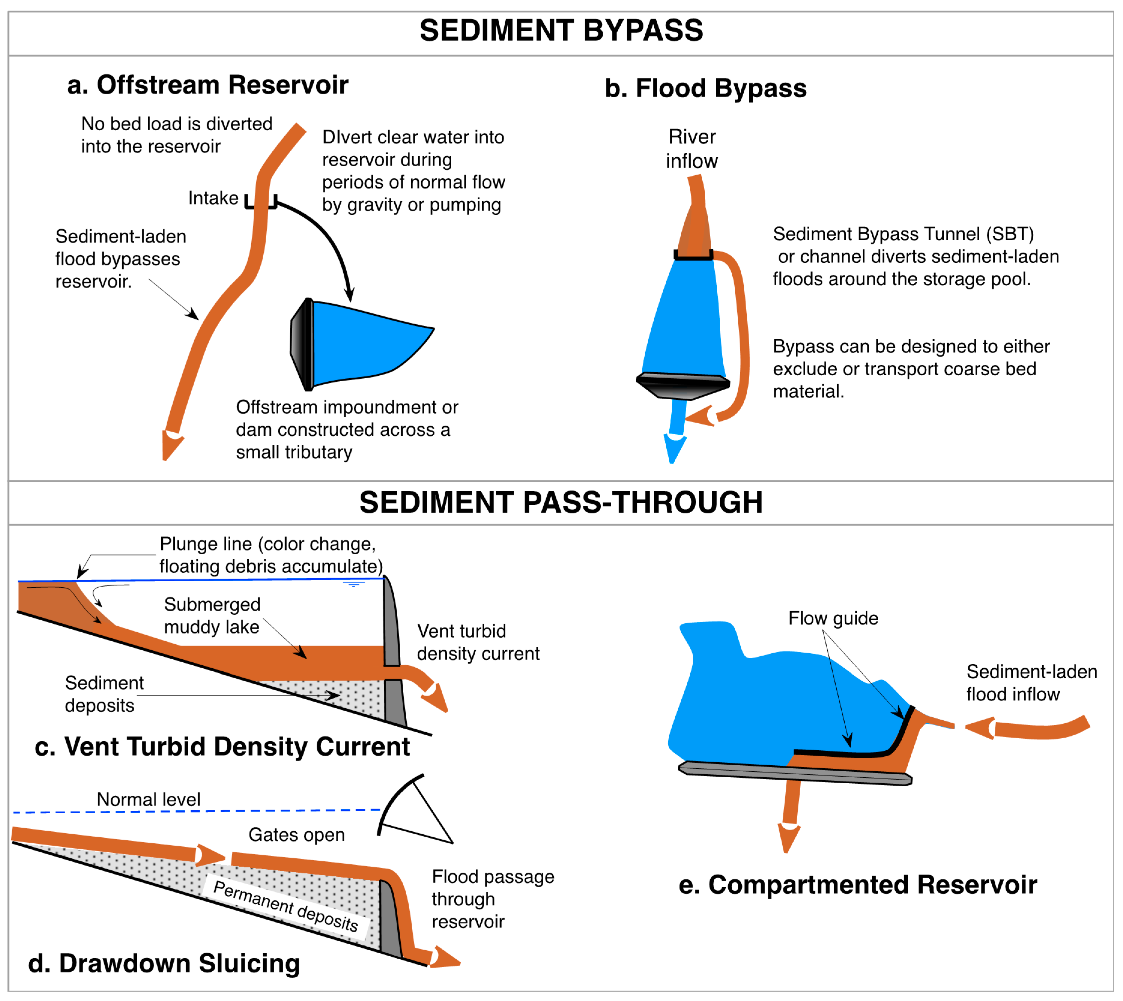
Routing strategies focus on maintaining inflowing sediment in motion (minimizing deposition), either passing sediment-laden floods around the storage zone (bypass) or though the storage zone (pass-through). The overall strategy can be summarized as, “Store clear water—release muddy flows.” This concept is particularly relevant where extreme sedimentation events can occur. Five basic strategies can be used to route sediments, as classified in Table 1. The basic hydraulic configuration of each strategy is outlined in Figure 3.

4.2. Offstream Reservoir

Offstream (off-channel) storage is constructed outside the main river channel by impounding a small tributary or constructing the impoundment in an upland area. Clear water is diverted into the offstream reservoir by gravity or pumping, but large sediment-laden flows bypass the storage. Offstream reservoirs have been used for water supply and as daily regulation storage for run-of-river hydropower. Offstream storage can be highly effective in reducing sedimentation. At two offstream municipal supply reservoirs constructed in Puerto Rico, Río Fajardo (18°17′35 N, 69°39′35” W) and Río Blanco (18°13′15” N, 65°46′49” W), this strategy was calculated to exclude more than 90% of the sediment load [43].
Gravity-fed offstream reservoirs have also been used for peaking storage in hydropower reservoirs. Examples include the San Francisco project in Colombia (5°02′57” N, 75°43′43 W), Tinguiririca in Chile (34°50′07” S, 70°33′18” W) and Hidro San José in Bolivia (17°11′28” S, 65°49′19” W). Desanders at the intake exclude most sand from the conveyance system and the storage pool, but finer material will collect and must be removed by either dredging or dry excavation.
Offstream storage offers several other important advantages in addition to sediment control. The coarse bed load remains in the river channel instead of being trapped in the reservoir, thereby maintaining the downstream transport of sediment having high geomorphic and ecological importance. Because the conveyance system does not need to be dimensioned to transport flood flows, it may be economically extended for significant distances thereby providing more flexibility in the siting of both the intake and storage components. For example, offstream siting made the two reservoirs in Puerto Rico feasible when suitable onstream sites were not available. Placing the dam outside of the main river greatly reduces the size of both river diversion works during construction and spillway capacity for the operational period, reducing both cost and overtopping risk.
The Knellpoort reservoir in South Africa offers an interesting example of offstream storage solving an existing sedimentation problem. Initially, the Welbedacht municipal supply reservoir (29°54′34” S, 26°51′37” E) was constructed on the Caledon River with the intent to control sedimentation by flushing. However, the combination of too-high placement of the outlets and too-short flushing durations limited flushing effectiveness, and 86% of its capacity was lost in 20 years [44]. In 1989 the Knellpoort offstream dam was constructed on a tributary ~15 km upstream to provide replacement capacity with better protection against sedimentation. River water is pumped to the new reservoir via a canal equipped with a desilting basin to remove sand to avoid sedimentation in the canal and help protect the off-channel reservoir. Releases are made back into the Caledon River to supply the intake for the water filtration plant at Welbedacht dam, where limited storage capacity and intake operation continues to be sustained by flushing.

4.3. Flood Bypass (Sediment Bypass Tunnel)

A sediment bypass system has an inlet upstream of the storage volume to be protected from sedimentation and diverts large sediment-laden flows to a point below the dam. Bypass systems typically consist of a sediment bypass tunnel (SBT), but a high-capacity open channel can also be used as in the case of the Nagle reservoir in South Africa (29°35′07 S, 30°37′28” E). They will frequently, but not always, have a diversion weir to guide bed material into the tunnel entrance. The term diversion weir is used because these structures must have the structural integrity of a weir. The term flow guide, used subsequently, is reserved for structures that merely guide flow but need not withstand hydrostatic or overflow forces.
Bypass tunnels have been used only infrequently to date, with approximately 30 examples worldwide [45]. Characteristics of 21 bypass tunnels located in Switzerland (10), Japan (6), Taiwan (3) and one each in Pakistan and France are summarized in Auel [46]. The oldest SBT example is the Karasuhara reservoir, Japan, built in 1905 as a retrofit to control rapid sedimentation. It has successfully protected the reservoir since that time. The Pfaffensprung (Amsteg) project, the first Swiss SBT built in 1922, was described in 1931 as the “Swiss method” for controlling sedimentation [47]. Six bypass tunnels reviewed by Albayrak et al. [48] reported average annual sediment release efficiencies (sediment outflow/sediment inflow) ranging from 31% to 98%. With an appropriate diversion weir, a bypass tunnel can divert essentially all incoming bed load, independent of the flood event [49].
Despite the small number of systems currently installed, interest in bypass tunnels is growing, especially since they can also be installed as a retrofit to existing projects. Bypass tunnels are constructed for super-critical flow, maximum velocities typically fall in the 10–15 m/s range, and to date tunnel lengths up 4.3 km have been constructed. Design examples and guidelines are available for multiple projects [46,49,50,51], and proceedings of the International Workshop on Sediment Bypass Tunnels in 2015, 2017, and 2019 provide a substantial body of information.
Sediment bypass systems can be designed to divert either suspended sediment plus bed load, or suspended load only. Three basic configurations have been used, as shown in Figure 4. Most systems built to date are type-A; these divert sediment upstream of the reservoir using a diversion weir to guide both bed and suspended load into the tunnel. Typically, the bypass system is opened only during the largest flows. However, it can also operate on a more regular basis during the wet season, submerging the weir to pass part of the flow downstream (e.g., for turbine operation) and bypassing the flow that exceeds the downstream requirement. When submerged, the weir acts as a skimming wall which allows surface water to overflow into the reservoir while the deeper flow with higher sediment concentration is directed into the tunnel. This strategy is used at the Pfaffensprung SBT, which operates approximately 100 days/year as opposed to only a few days per year at most other sites.
The entrance to the high-level (type-A) SBT at Asahi reservoir in Japan is photographed in Figure 5a showing the entrance to the tunnel located immediately upstream of the diversion weir. At high flood flows the tunnel entrance is submerged by backwater from the check dam and creates orifice flow. During submergence, the low velocity in front of the submerged SBT entrance will not transport coarse sediment into the tunnel. When the flow rate and water level diminish, and free flow again occurs at the tunnel entrance, the high velocity shallow flow will again transport coarse material into the tunnel. This sequence is illustrated in Figure 5b.
A second configuration, labeled type-B in Figure 4, installs the bypass entrance further downstream and at a lower level, thereby reducing the tunnel length. Under this configuration, the reservoir must be drawn down to mobilize bed material or delta sediments through the tunnel and to prevent the delta from advancing downstream and overtopping the normally-submerged diversion weir. Without drawdown and flushing through the SBT, the delta will advance to and spill over the weir, leaving only a scour cone in front of the tunnel entrance (pressure flushing, as described subsequently). Between flushing events this configuration can also be used to bypass suspended sediment or turbidity currents when the reservoir is at a high level.
The Solis hydropower peaking reservoir in Switzerland is an example of a low-level SBT with a diversion weir. For a flushing event the water level is drawn down to allow the weir to emerge from the water, causing bed material from the advancing delta to be scoured and directed into the tunnel entrance weir [53,54].
A serious limitation in bypass systems is abrasion of the tunnel floor by coarse bed load, gravel and cobbles [55]. It may be important to exclude this material from a bypass tunnel. The 30 Mm3 multi-purpose Miwa dam in Japan (Figure 6) uses a high-level SBT with a diversion weir (type-A) but eliminates coarse bed material from the bypass tunnel by trapping sediment with an upstream check dam. The coarse material is extracted commercially and the transit of coarse material through the bypass tunnel is largely eliminated. Several other similar arrangements in Japan are described in Onda et al. [56].
The third configuration, type-C in Figure 4, can exclude bed material from the tunnel by eliminating the diversion weir and releasing the bed material by other means. This configuration is being used as a turbid density current bypass at Shihmen reservoir in Taiwan; coarse bed material that forms a delta is removed by commercial excavation further upstream [58].
Type-C configurations are also being designed at peaking run-of-river hydropower plants in Nepal, to control sedimentation and also create a sedimentation headpond that acts as a desander upstream of the intake. Design of the reservoir to eliminate desanders is attractive because these hydropower plants have design flows as high as 650 m3/s and annual sediment loads can exceed 20 Mt/year, consisting predominately of highly abrasive and angular quartz particles. A conventional design would require large desanders (sedimentation basins) which must be excavated underground due to the mountainous topography, resulting in desanders that cost much more than the dam itself.
The overall layout and operational concept are illustrated, respectively, by Figure 7a and Table 2. The bypass tunnel diverts all flow exceeding the turbine design capacity, limiting the flow rate entering the headpond to provide predictable hydraulic characteristics. In these Nepali mountain reservoirs the river canyons are narrow and much of the original reservoir width can be maintained free of sediment by flushing through high-capacity low-level outlets. However, after the sediment equilibrium profile has been attained, reservoir volume is small compared to annual sediment inflow and, in some cases, the reservoir would fill with sediment in a single monsoon season without sediment management.
The flow arriving at the SBT inlet will have a vertical concentration gradient, and to maximize sediment bypass efficiency a flow guide may be used to aspire water with higher-concentration from deeper in the water column, as seen in Figure 7b. The bypass system will operate throughout the monsoon, approximately 120 days per year, and flow will be continuously variable over this time. Use of an overflow weir at the tunnel entrance eliminates the need to continuously modulate a mechanical gate to control the diversion rate. The SBT weir crest is set so that the full reservoir level is reached when the weir and tunnel attain peak design flow.
Bypassing as much sediment as possible reduces the load entering the sedimentation headpond, prolonging the interval between flushing events needed to remove sediment accumulating in the headpond. The flushing trigger has multiple components including a minimum threshold flow, a minimum time since the prior flushing event to prevent multiple flushing events one after another in wet years, and the sediment volume computed to have accumulated in the reservoir. Initiation of drawdown for flushing may be curtailed at very high inflows due to restrictions in the allowable downstream release rate.
Lacking a diversion weir to force all the flow into the tunnel, placement of the inlet to the type-C tunnel is critical to maximize sediment entrainment. Even though velocities along the reservoir are not high as compared to rivers, stratified flow and secondary currents do occur and influence sediment distribution. Therefore, just as in the siting of a river intake, both large-scale secondary circulation associated with flow path curvature, as well as the localized eddies that respond to inlet geometry, must be carefully evaluated. When a type-C bypass and a large capacity power intake are operating simultaneously, physical modeling has clearly shown that the suspended sediment concentration in the diverted water is sensitive to secondary currents at both scales. Physical and 3-D numerical modeling are critical tools to optimize design of the inlet configuration to maximize sediment bypass.

4.4. Turbidity Current Venting

Turbid density currents are sediment-laden flows that plunge beneath the impounded water and travel along the reservoir thalweg due to the density difference between the clear water and the sediment-laden flow. Under favorable conditions they can travel tens of kilometers along the submerged thalweg to the dam where they either accumulate as a submerged “muddy lake” or are released (Figure 3c). The plunge line is photographed in Figure 8. Because the plunging flow sets up a localized upstream-moving surface current, floating debris carried by the river become trapped in this area. Although density currents occur frequently in reservoirs due to differences in temperature as well as sediment concentration, they frequently fail to transport significant amounts of sediment to the dam. Bathymetric surveys revealing horizontal sediment beds that extend upstream from the dam creating a wedge-shaped deposit, as illustrated in Figure 3c, are a clear indicator that turbidity currents transport significant volumes of sediment to the dam.
Turbid density currents usually transport fine sediment that can pass hydropower turbines with minimal abrasion, presenting an opportunity for their release. In contrast, coarse delta sediments will cause catastrophic damage to all types of hydro-mechanical equipment. The release of density currents through turbines is a highly beneficial long-term strategy because it reduces the rate of storage loss, thereby maximizing the volume available to store coarse sediment and delay arrival of the delta to the intake. One of the primary sediment management objectives in hydropower reservoirs is to retard the approach of delta sediments to intake area, since delta sediments typically require costly mitigation measures.
Turbidity current motion is facilitated when the submerged current flows along a defined channel. However, as the submerged channel is filled with the sediment deposited by successive turbidity flows, the reservoir bottom becomes flat and wide causing the turbidity current to spread out. This produces a wide and shallow turbidity flow with an enlarged frictional boundary that retards forward motion, reducing sediment transport capacity and allowing coarser sediments to settle out of the current. The large upper interface facilitates dilution with clear water. Both processes lower the current’s density and velocity, allowing more sediment to deposit, causing the current to stall. Thus, turbidity currents that reach the dam by following the original river channel during the first years of impounding may dissipate after the bottom collects sediment and flattens. A submerged channel which helps sustain turbidity current motion to an outlet at the dam can be maintained by empty flushing or dredging [59].
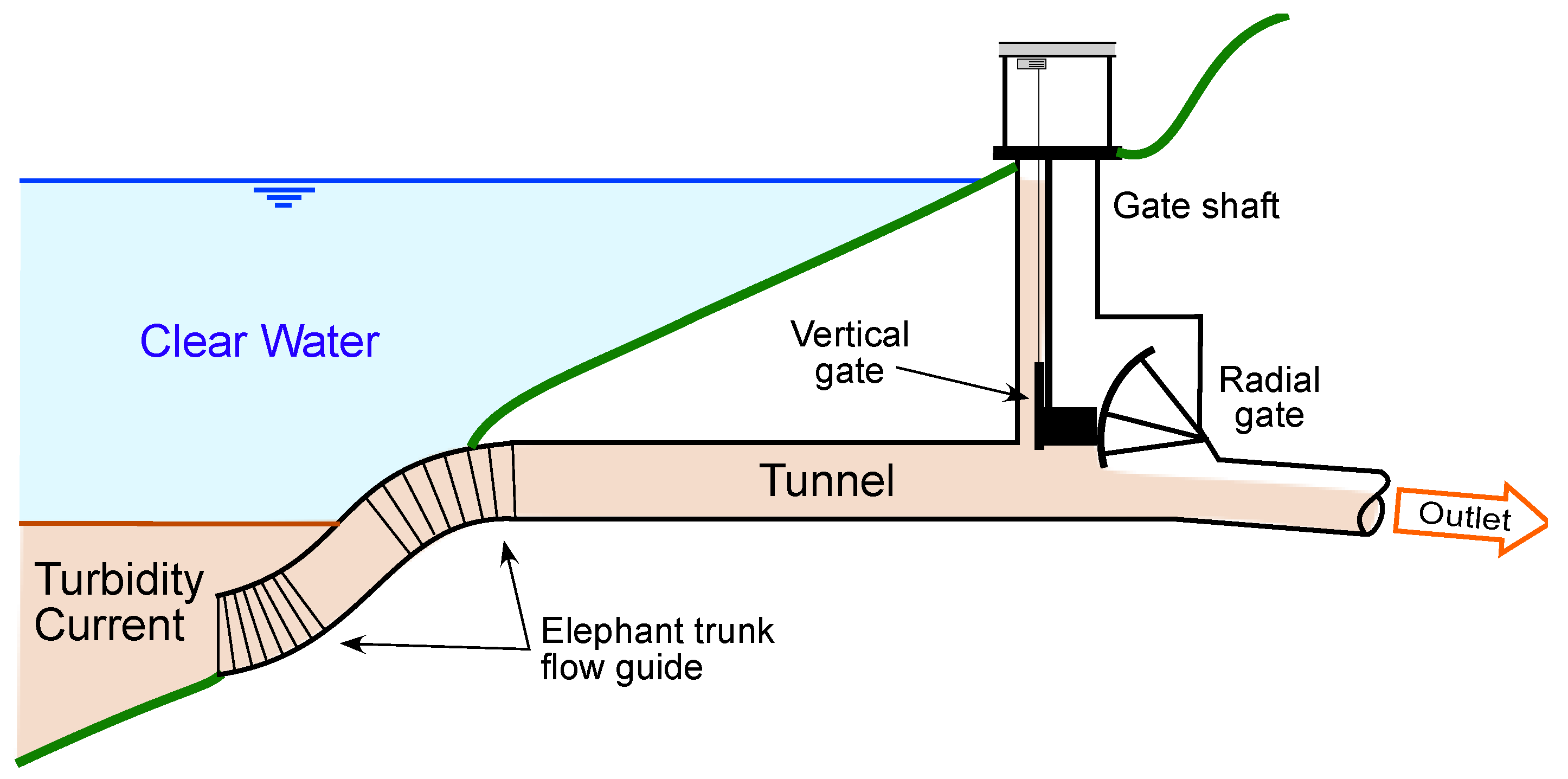
Deep outlets to release turbidity currents are costly. However, a turbidity current can be aspired up to a higher level outlet using a flow guide, as conceptually illustrated in Figure 9 showing the “elephant trunk” flow guide at the Zengwen (Tzengwen) reservoir in Taiwan, built in 2018 with a design discharge of 995 m3/s. The flow guide does not need to withstand hydrostatic pressure as it merely directs the flow upward. Outlet operation can be optimized based on estimating the occurrence and arrival time of turbidity currents [60].

4.5. Sediment Sluicing by Reservoir Drawdown

Sediment sluicing refers to the practice of maximizing sediment passage through a reservoir by lowering the water level during a flood. This deceases hydraulic retention time (increases flow velocity), helping to maintain sediment in motion and reducing the opportunity for it to become trapped. Sluicing focuses on passing flood-borne sediment downstream at the same rate it enters the reservoir. Depending on hydrology and other site-specific conditions, sluicing can be performed on a seasonal basis (e.g., monsoon), or may be event based, with reservoir operation guided by real-time reporting gages and hydrologic modeling.
Flood events suitable for sediment sluicing may also be suitable for sediment bypass. The difference between the two strategies is that the bypass system diverts the flood (or turbidity current) to reduce the sediment load entering the downstream portion of the reservoir, while sluicing releases are made at or near the dam.
Sluicing is most effective in hydrologically small reservoirs which capture only a fraction of annual runoff volume and have a deep high-capacity low-level outlet. Existing concrete dams in Japan have been notched and retrofitted with deeper gates to facilitate sediment sluicing [61]. While sluicing is most effective in elongated reservoirs, even in a shallow and nearly circular reservoir having poor geometry for sediment release, limited drawdown which reduces flood detention time can reduce sediment trapping [62]. Even though sluicing may represent only an incremental improvement in the sediment balance, it can represent a very inexpensive technique to reduce the amount of sediment that must be eventually removed by a more costly technique (e.g., dredging). Because sediment will eventually reduce the storage capacity of even the largest reservoirs, sluicing may become attractive later in the reservoir life as its storage capacity shrinks, even though it was not considered feasible during earlier years.
With its focus on passing inflowing sediment loads downstream during flood events, sediment sluicing does not generate the high suspended sediment concentrations typically associated with emptying and flushing a reservoir. Even when sluicing scours and removes previously deposited sediment, because of the large flow rates involved the peak sediment concentrations are much lower than for flushing. It may be considered an environmentally friendly technique.
Because previously deposited sediment can be removed by both sluicing and flushing, the differentiation between these techniques can be ambiguous. The parameters in Table 3 can help distinguish between the two processes. Sluicing passes the natural hydrograph and its associated sediment through the reservoir with as little attenuation as possible, maintaining natural patterns of flow and sediment transport below the dam. This minimizes downstream environmental impacts. On the other hand, flushing can release very high peak sediment concentrations (e.g., >100,000 mg/l) and may require complex environmental monitoring and mitigation measures.

4.6. Compartmented Reservoir

In some situations, it may be feasible to maximize the hydraulic short-circuiting of sediment-laden inflows by manipulating reservoir geometry using an internal barrier, as indicated in Figure 3e, or by modifying geometry by dredging. Alternatively, the reservoir may be subdivided using structural barriers, allowing the compartments to be treated as two separate reservoirs with water-level differences between them. This strategy is being implemented at the Wonogiri reservoir in Indonesia, described below.
The 730 Mm3 Wonogiri reservoir (7°50′14” S, 110°55′42” E) on the Bengawan Solo River, is a multi-purpose reservoir (irrigation, flood control, hydropower, fisheries and recreation). It began filling in 1981, but it soon became apparent that the reservoir was filling with sediment at an accelerated rate. The Keduang River, a tributary that drains the slopes of Mt. Lawu, discharges near the dam and represents 31% of the 1343 km2 reservoir catchment but delivers 38% of the sediment [63]. Topography allowed construction of an interior barrier to divide the reservoir into two parallel storages, the main reservoir and a smaller sediment storage reservoir fed by the Keduang River. Two new spillways were constructed: one allows water from the sediment storage reservoir to overflow into the main reservoir, as needed, and a new spillway on the main dam’s right abutment allows the downstream discharge of water and sediment from the sediment storage reservoir during sediment sluicing and flushing events. The basic operating strategy is to preferentially make downstream deliveries from the sediment storage reservoir, releasing as much sediment downstream as possible, while conserving the water in the main storage reservoir. This minimizes the need to replenish main reservoir storage from the sediment reservoir. The optimized operating rule under this new configuration can improve water flood control performance and achieve more stable water levels in the main reservoir, but water supply reliability will be impaired unless sediment release is limited to wet years [64].

5. Sediment Removal

5.1. Pressure Flushing

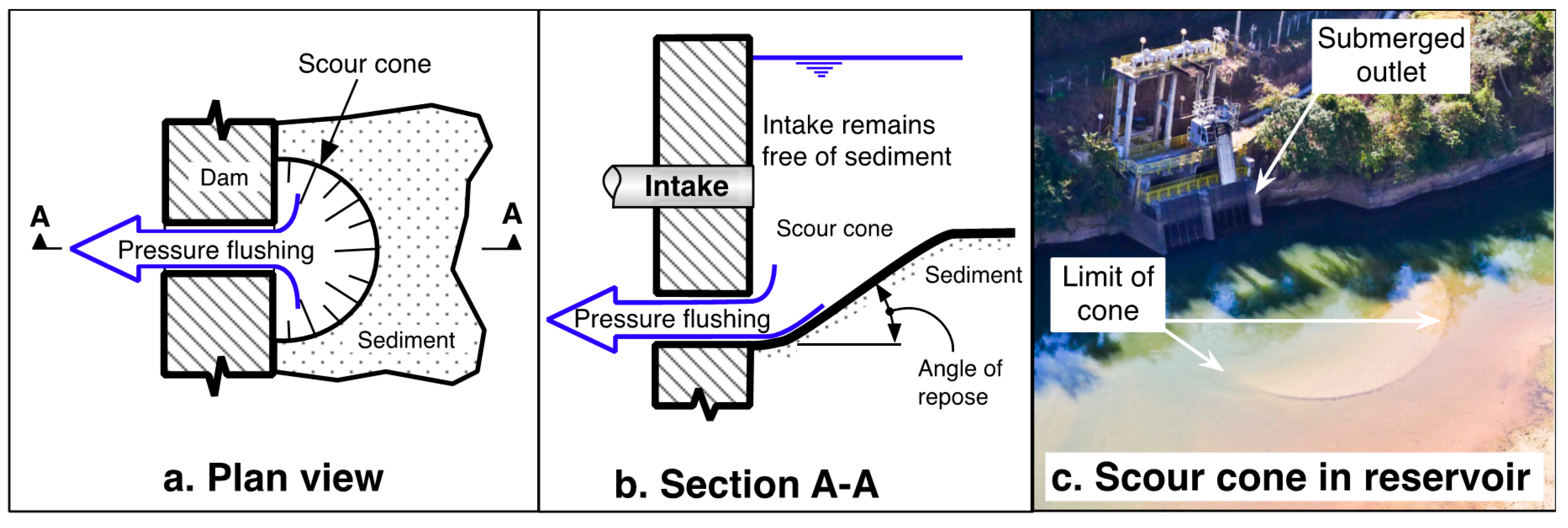
The term flushing refers to the removal of previously deposited sediments by hydraulic scour. Pressure flushing occurs when a low-level outlet or an intake is opened to release sediment while the reservoir level is high, producing a localized scour cone immediately adjacent to the submerged outlet. Sediment removal is limited to the area immediately upstream of the outlet (Figure 10). A scour cone will also naturally develop in front of an outlet subject to sediment encroachment (Figure 10c).

5.2. Empty Flushing

Empty flushing, or simply flushing, involves emptying the reservoir to allow the river to flow across and erode the exposed deposits, transporting the eroded sediment through low-level outlets (LLOs) and beyond the dam. The sequence observed during empty flushing is summarized in Figure 11. The flushing process involves three stages [14]:
  • Drawdown. As the reservoir is drawn down, upstream sediment deposits are scoured, transported closer to the dam and redeposited. Opening the LLOs during this period typically does not result in large amounts of sediment release. The drawdown rate may be limited by factors such as gate capacity, downstream channel capacity, and restrictions imposed by stability of the dam or reservoir rim.
  • Empty. As shown by the graphs in Figure 11, as the level drops to near empty to initiate the free-flow period, sediment that has been incrementally transported toward the dam during drawdown is now flushed out of the reservoir, producing peak concentrations.
  • Refill. When reservoir refill begins, it may be necessary to continue to release clear water downstream to help flush released sediment through the downstream river channel.
The full flushing sequence may typically require anywhere from a day to a month, depending on the size of the reservoir and sediment volume to be released. In larger storage reservoirs, flushing may be scheduled at the end of the drawdown period, when the reservoir is already at its minimum level, passing the early wet-season flows through the reservoir with LLOs open prior to initiation of annual refill. Downstream impacts may be reduced by flushing more frequently with less sediment release per event. When reservoirs occur in close sequence along a river, flushing operations should be coordinated [66].
Sediment-laden flushing flow can impact not only aquatic life but also downstream infrastructure such as water supply intakes, etc. Downstream impacts to aquatic species depend on both the magnitude and duration of high sediment concentration, plus factors such as oxygen content in the released water, oxygen demand by the sediment, and the presence of contaminants. Management of drawdown rate, dilution of high concentration flow with clear water, interval between flushing events, timing to avoid spawning or other biologically sensitive periods, and post-flushing releases of clear water can all be important environmental mitigation tools [67,68,69].
Although sluicing may be regarded as a special case of flushing [70], they are generally classified as a separate techniques due to important differences, especially in terms of their downstream impacts. Differences between sluicing and flushing were summarized in Table 3. Most notably from the environmental standpoint, sluicing does not generate the high peak values of sediment concentration that are characteristic of flushing.

5.3. Scour Channel Geometry Sustained by Sluicing or Flushing

Flushing and sluicing both use scour during drawdown to create and sustain a channel along the length of the reservoir. The long-term volume that can be sustained by either method is determined by this channel geometry, defined by the average channel width, longitudinal profile, and channel side slope, as illustrated in Figure 12 [70,71,72]. Scour channel width in reservoirs increases as the square root of discharge [70], a relationship also found in natural rivers [73]. This implies that a sluicing strategy with large discharge will sustain more long-term reservoir capacity than will flushing with a lower discharge. The width of the scour channel will be similar to the natural pre-impoundment alluvial channel if large scour flows are possible. Sediment deposited outside the scour channel cross-section will not be removed unless it is moved into the channel mechanically (e.g., bulldozer) or by lateral flows, as described in the Heisonglin reservoir case study [14]. This makes it important to scour with the largest flows possible to maximize bottom width. Partial reservoir drawdown during floods (sluicing) can also reduce sedimentation outside the scour channel.

5.4. Dry Excavation

Dry excavation requires lowering the reservoir level to allow access to deposits by earthmoving equipment. At sites with seasonal water-level variation, dry excavation in delta areas can be undertaken during periods of natural drawdown. Dry excavation can easily remove coarse material from deltas comprised of coarse sediment that dewaters readily, and delta sediments at some reservoirs is sold as commercial aggregate. However, the removal of poorly consolidated fine sediment is typically not practical with conventional earthmoving equipment unless the sediment has been dewatered for sufficient time to permit drainage and consolidation. If suitable disposal sites are distant, the impacts associated with transport by truck along local roads or highways can be significant due to traffic, noise, road damage, and sediment dispersal along the route.

5.5. Dredging

Dredging refers to the excavation of material from beneath the water. There are broadly two types of dredging: (1) mechanical-lift dredging removes sediment by buckets such as a backhoe, clamshell, dragline, or bucket ladder, placing the excavated material into a barge or truck for transport; (2) hydraulic dredging mixes sediment with water for transport in a slurry pipeline, re-introducing the sediment back to the river below the dam, or discharging to a containment area for dewatering. The dewatered sediment may then be hauled away to permit reuse of the containment area, or as in the case of Lake Springfield in the USA the dewatered sediments were subsequently used as farmland [14]. Basson and Rooseboom [74] summarize experience with reservoir dredging in South Africa.
Most reservoir sediments are removed by hydraulic dredges. They can achieve high rates of production handling a wide range of grain sizes, do not use a large volume of water or interfere with normal reservoir operation, and slurry pipeline is a clean and low-impact means to convey dredged material to the discharge point. A special type of hydraulic dredging developed for reservoirs is the siphon or hydrosuction dredge [75,76], which uses the difference in hydraulic head between the reservoir water surface and a discharge point near the base of the dam as the energy source for slurry transport. The hydraulic energy available is fixed by the reservoir level, which may vary. Friction losses in the slurry pipeline typically limit the use of siphon dredges to within a few kilometers of the dam.
A critical limitation to dredging is its high cost. This cost is reduced by discharging to the river below the dam instead of upland disposal sites. At hydropower sites cost can be reduced by using self-generated electrical energy for dredging. The availability of land for sediment disposal represents both an economic and a physical limitation. Smaller reservoir dredging projects may discharge to upland disposal areas, but for large dredging volumes this does not represent a sustainable long-term strategy due to the volume of material involved. Eventually, the objective is to restore sediment transport along the fluvial system, implying the withdrawal of sediment from the reservoir and re-introducing it into the river below the dam. This strategy implies essentially continuous dredging as opposed to large dredging campaigns at intervals of decades.

6. Adaptive Strategies

Adaptive strategies are techniques that seek to mitigate sedimentation impacts by methods other than adjusting the reservoir’s sediment balance. These have been grouped into the six broad categories in Table 4, and they may be used independently or in combination with other strategies.

6.1. Focus or Redistribute Sediment

Reservoir delta profiles are influenced by the operating rule. When a reservoir is drawn down to a consistent minimum elevation each year, the delta will establish a relatively stable profile and most inflowing sediment will be deposited on the delta face (foreset bed), which advances toward the dam, as seen in Figure 13a. To retard delta advance, the reservoir’s minimum operating level may be gradually raised, focusing new deposits onto the top of the delta as seen in Figure 13b. Conversely, a reservoir may be drawn down during floods to scour and move the delta deposits deeper into the impoundment, for example, to reduce backwater and upstream flood levels and to minimize sediment deposition in the upper pool.

6.2. Increase Storage

At some sites it may be possible to increase storage by constructing a new reservoir, as with the Knellpoort offstream reservoir discussed previously, or by raising the dam. Because reservoir surface area increases with elevation, even a relatively small raise can often produce a substantial volume increase.

6.3. Improve Operational Efficiency

Operational efficiency may be enhanced at both the project and the regional level to optimize the benefits from a declining storage volume. Operational changes can also more equitably distribute sedimentation impacts across different beneficial use pools. Sedimentation does not affect all pools equally, and beneficial pool volumes may be impacted before the designated sediment storage pool is filled. For instance, the normally empty flood control pool occupies the upper portion of a multi-purpose reservoir while the normally full conservation pool occupies the lower level. The flood control pool will typically experience much less sedimentation than the lower pool(s). Pool limits may be modified to reallocate the storage loss in a more equitable manner among the beneficial uses.
Operating rules at many reservoirs were established more than 50 years ago. However, present-day tools for real-time hydrologic monitoring and modeling make it possible to improve operations as compared to what was possible when the reservoir was built. Conjunctive use opportunities may also exist, such as managed aquifer recharge using reservoir releases during wet years. Revisions to the operational rule may enable project benefits to be temporarily sustained for all users, despite continuing storage loss, or to maximize benefits from a smaller but stabilized storage capacity [15]. Improvements in operational efficiency are typically very inexpensive compared to any other type of sediment management.

6.4. Modify Infrastructure

Sediment may eventually encroach on and impact critical structures such as intakes, spillways, gates, and hydropower equipment. The toe of the advancing reservoir delta corresponds to the transition from sandy delta sediment to fine sediment [77]. Gradual encroachment by fine sediment will typically not represent a major problem for mechanical equipment such as pumps and turbines, and to maximize sediment release from the reservoir it is preferred to pass this fine sediment downstream. However, delta sediments are highly abrasive and will severely damage hydro-mechanical equipment, making it necessary to exclude them from intakes. As delta deposits approach the dam, deep intakes may be raised to avoid encroaching sand, turbine runners may receive abrasion-resistant coatings as the sand load increases, etc. Upstream of the reservoir, highway or other infrastructure may be threatened and require modification as the delta grows vertically and extends upstream of the normal pool level [44].

6.5. Adjust to Reduced Benefits

As water supply reliability declines due to storage loss, it becomes increasingly important to use available water more efficiently. This includes reduction of physical water losses as well as conservation by users, such as more efficient irrigation techniques or shift to less water-intensive activities. However, projects to “increase efficiency” should be evaluated from perspective of the regional water budget. For example, if seepage from irrigation canals represent a critical source of aquifer recharge, lining of earthen canals to reduce “losses” may be nothing more than a costly way to diminish groundwater supplies, with no overall gain in water availability.
Adjustments to reduced water availability may also entail economic transitions into activities that are inherently more water efficient. Given the large differences in the economic benefits of water use among different activities, significant reductions in water use may have only modest economic consequences. Irrigation, the largest consumptive water user, frequently has large opportunities for efficiency increases, or for shifts away from low-value to higher-value crops. For example, Hanak [78] noted that, “California’s economy has become less reliant on water intensive activities. For instance, agriculture and related manufacturing account for nearly four-fifths of all business and residential water use—but make up just 2 percent of state GDP and 4 percent of all jobs”.

6.6. Re-purpose or Decommission

The long-term sustainable use of all reservoirs is not justified, and a dam may be decommissioned when sedimentation renders it no longer economic to operate. Acceptable repurposing or decommissioning strategies should be developed at any dam for which sustainable use is not considered feasible. In the case of dams with high decommissioning costs, this cost may be an important factor driving sediment management to delay or avoid the decommissioning event. Several guidelines are available that focus of the downstream consequences of sediment release in response to dam removal [79,80,81].

7. Discussion

A wide variety of strategies are available to improve the sediment balance across reservoirs and adapt to the consequences of sediment encroachment and storage loss. Multiple strategies will typically be employed at a given reservoir. Because it is rarely possible to restore and maintain original reservoir capacities, adaptive strategies can be particularly important.
Different strategies may be applied simultaneously or sequentially over time. They may also be applied to reservoirs in series along a river. Sequencing of interventions can occur as sedimentation progresses and more aggressive strategies become necessary. Some strategies, such as turbidity current venting, may be more appropriate in a new storage reservoir, as opposed to strategies such as sluicing, flushing and dredging that are typically more applicable as reservoir volume is diminished by sedimentation. When developing sustainable sediment management plans for reservoirs, identify both immediate and future strategies, and ensure that near-term actions also support any identified future strategies. Software such as RESCON2 [17], currently in revision, can be useful as an initial screening tool, but must always be carefully verified because sediment management issues are typically both complex and site-specific.
Sediment management using the strategies described in this paper is essential if we are to sustain the long-term capacity of reservoirs to regulate water. The first step is to identify and prioritize sites with significant problems and important consequences. Experience gained from the first implementation sites will facilitate application across larger numbers of reservoirs, as will inevitably be required. Successful management will require a paradigm shift by owners, engineers, and regulators, who must come to understand the need and plan for the restoration of sediment flows along the fluvial system.
Erosion is a geologic process that can be reduced in disturbed environments, but it can never be stopped. Sediments cannot be captured forever; they will eventually move downstream to the ocean. Releasing sediments downstream can have environmental benefits and reduce channel erosion but can adversely affect downstream ecosystems and infrastructure such as intakes and reservoirs that have been developed in a clear water environment. Restoration of downstream sediment flows may increase water treatment costs, the requirement for navigational and canal dredging, and impact flood levels if river channel capacity diminishes. However, we cannot trap sediment forever, and the restoration of sediment continuity along fluvial systems is a complex problem that cannot be avoided.

Funding

This research received no external funding.

Conflicts of Interest

The author declares no conflict of interest.

References

  1. Syvitski, J.P.M.; Vörösmarty, C.J.; Kettner, A.J.; Green, P. Impact of humans on the flux of terrestrial sediment to the global coastal ocean. Science 2005, 308, 376–380. [Google Scholar] [CrossRef] [PubMed]
  2. Vörösmarty, C.J.; Meybeck, M.; Fekete, B.; Sharma, K.; Green, P.; Syvitski, J.P.M. Anthropogenic sediment retention: Major global impact from registered river impoundments. Glob. Planet. Chang. 2003, 39, 169–190. [Google Scholar] [CrossRef]
  3. Annandale, G. Quenching the Thirst: Sustainable Water Supply and Climate Change; CreateSpace Independent Publishing Platform: North Charleston, SC, USA, 2013; ISBN 978-1-4802-6515-8. [Google Scholar]
  4. Randle, T.; Morris, G.; Whelan, M.; Baker, B.; Annandale, G.; Hotchkiss, R.; Boyd, P.; Minear, J.T.; Ekren, S.; Collins, K.; et al. Reservoir Sediment Management: Building a Legacy of Sustainable Water Storage Reservoirs. In National Reservoir Sedimentation and Sustainability Team White Paper; SEDHYD, Inc.: Denver, CO, USA, 12 June 2019; p. 57. Available online: https://www.sedhyd.org/reservoir-sedimentation/National%20Res%20Sed%20White%20Paper%202019-06-21.pdf (accessed on 10 March 2020).
  5. Wisser, D.; Frolking, S.; Hagen, S.; Bierkens, M.F.P. Beyond peak reservoir storage? A global estimate of declining water storage capacity in large reservoirs. Water Resour. Res. 2013, 49, 5732–5739. [Google Scholar] [CrossRef] [Green Version]
  6. Central Water Commission. Compendium of Silting of Reservoirs in India; Central Water Commission: New Delhi, India, 2015. [Google Scholar]
  7. Annandale, G.W.; Morris, G.L.; Karki, P. Extending the Life of Reservoirs: Sustainable Sediment Management for Dams and Run-of-River Hydropower; The World Bank: Washington, DC, USA, 2016; ISBN 978-1-4648-0837-1. [Google Scholar]
  8. Kondolf, G.M. Hungry water: Effects of dams and gravel mining on river channels. Environ. Manag. 1997, 21, 533–551. [Google Scholar] [CrossRef] [PubMed]
  9. Torres, A.; Brandt, J.; Lear, K.; Liu, J. A looming tragedy of the sand commons. Science 2017, 357, 970–971. [Google Scholar] [CrossRef]
  10. Slagel, M.J.; Griggs, G.B. Cumulative losses of sand to the California coast by dam impoundment. J. Coast. Res. 2008, 243, 571–584. [Google Scholar] [CrossRef]
  11. Willis, C.M.; Griggs, G.B. Reductions in fluvial sediment discharge by coastal dams in California and implications for beach sustainability. J. Geol. 2003, 111, 167–182. [Google Scholar] [CrossRef]
  12. Brown, C.B. The Control of Reservoir Silting; U.S. Govt. Printing Office: Washington, DC, USA, 1944; p. 166. [Google Scholar]
  13. Eakin, H.M.; Brown, C.B. Silting of Reservoirs; U.S. Department of Agriculture: Washington, DC, USA, 1939. [Google Scholar]
  14. Morris, G.L.; Fan, J. Reservoir Sedimentation Handbook. McGraw-Hill Book, Co.: New York, NY, USA, 1998. [Google Scholar]
  15. Kantoush, S.A.; Sumi, T. The aging of Japan’s dams: Innovative technologies for improving dams water and sediment management. In River Sedimentation, Proceedings of the 13th International Symposium on River Sedimentation, ISRS 2016, Stuttgart, Germany, 19–22 September 2016; CRC Press: Boa Raton, FL, USA, 2017; pp. 1030–1037. ISBN 978-1-317-22531-7. [Google Scholar]
  16. Morris, G.L. Sediment management and sustainable use of reservoirs. In Modern Water Resources Engineering; Wang, L.K., Yang, C.T., Eds.; Humana Press: Totowa, NJ, USA, 2014; pp. 279–337. ISBN 978-1-62703-594-1. [Google Scholar]
  17. Efthymiou, N.; Palt, S.; Annandale, G.W.; Karki, P. Rapid Assessment Tool for Sustainable Sediment Management (RESCON2): User Manual; World Bank: Washington, DC, USA, 2017. [Google Scholar]
  18. Basson, G.R.; Rooseboom, A. Dealing with Reservoir Sedimentation: Guidelines and Case Studies; Intl. Commission on Large Dams: Paris, France, 1999. [Google Scholar]
  19. Kondolf, G.M.; Gao, Y.; Annandale, G.W.; Morris, G.L.; Jiang, E.; Zhang, J.; Cao, Y.; Carling, P.; Fu, K.; Guo, Q.; et al. Sustainable sediment management in reservoirs and regulated rivers: Experiences from five continents. Earths Future 2014, 2, 256–280. [Google Scholar] [CrossRef]
  20. Pimentel, D.; Harvey, C.; Resosudarmo, P.; Sinclair, K.; Kurz, D.; McNair, M.; Crist, S.; Shpritz, L.; Fitton, L.; Saffouri, R.; et al. Environmental and economic costs of soil erosion and conservation benefits. Science 1995, 267, 1117–1123. [Google Scholar] [CrossRef] [Green Version]
  21. Panagos, P.; Standardi, G.; Borrelli, P.; Lugato, E.; Montanarella, L.; Bosello, F. Cost of agricultural productivity loss due to soil erosion in the European Union: From direct cost evaluation approaches to the use of macroeconomic models. Land Degrad. Dev. 2018, 29, 471–484. [Google Scholar] [CrossRef]
  22. Hunink, J.E.; Niadas, I.A.; Antonaropoulos, P.; Droogers, P.; de Vente, J. Targeting of intervention areas to reduce reservoir sedimentation in the Tana catchment (Kenya) using SWAT. Hydrol. Sci. J. 2013, 58, 600–614. [Google Scholar] [CrossRef] [Green Version]
  23. Zeleke, G.; Hurni, H. Implications of land use and land cover dynamics for mountain resource degradation in the northwestern Ethiopian highlands. Mt. Res. Dev. 2001, 21, 184–191. [Google Scholar] [CrossRef] [Green Version]
  24. Zeleke, G. Exit Strategy and Performance Assessment for Watershed Management: A Guideline for Sustainability; Water and Land Resource Center of Addis Ababa University: Addis Ababa, Ethiopia, 2015. [Google Scholar]
  25. Creech, E. Saving Money, Time and Soil: The Economics of No-till Farming. 2017. Available online: https://www.usda.gov/media/blog/2017/11/30/saving-money-time-and-soil-economics-no-till-farming (accessed on 10 March 2020).
  26. Trimble, S.W. Man-Induced Soil Erosion on the Southern Piedmont 1700–1970; Soil and Water Conservation Society: Ankeny, Iowa, 1978. [Google Scholar]
  27. Islam, R.; Reeder, R. No-till and conservation agriculture in the United States: An example from the David Brandt farm, Carroll, Ohio. Int. Soil Water Conserv. Res. 2014, 2, 97–107. [Google Scholar] [CrossRef] [Green Version]
  28. Renwick, W.H.; Andereck, Z.D. Reservoir sedimentation trends in Ohio, USA: Sediment delivery and response to land-use change. In Proceedings of the Sediment Dynamics and the Hydromorphology of Fluvial Systems; IAHS: Dundee, UK, July 2006; Publ. 306. [Google Scholar]
  29. Rustomji, P.; Zhang, X.P.; Hairsine, P.B.; Zhang, L.; Zhao, J. River sediment load and concentration responses to changes in hydrology and catchment management in the Loess Plateau region of China: Loess plateau sediment yield. Water Resour. Res. 2008, 44. [Google Scholar] [CrossRef]
  30. Wang, S.; Fu, B.; Piao, S.; Lü, Y.; Ciais, P.; Feng, X.; Wang, Y. Reduced sediment transport in the Yellow River due to anthropogenic changes. Nat. Geosci. 2016, 9, 38–41. [Google Scholar] [CrossRef]
  31. Minear, J.T.; Kondolf, G.M. Estimating reservoir sedimentation rates at large spatial and temporal scales: A case study of California: Technical note. Water Resour. Res. 2009, 45. [Google Scholar] [CrossRef] [Green Version]
  32. Mekonnen, M.; Keesstra, S.D.; Stroosnijder, L.; Baartman, J.E.M.; Maroulis, J. Soil Conservation Through Sediment Trapping: A Review. Land Degrad. Dev. 2015, 26, 544–556. [Google Scholar] [CrossRef]
  33. Renwick, W.H.; Smith, S.V.; Bartley, J.D.; Buddemeier, R.W. The role of impoundments in the sediment budget of the conterminous United States. Geomorphology 2005, 71, 99–111. [Google Scholar] [CrossRef]
  34. Hu, C.; Wu, D.; Jayakumar, R.; Ajisawa, S. Warping Dams Construction and its Effects on Environment, Economy, and Society in Loess Plateau Region of China; Intl. Research and Training Center on Erosion and Sedimentation: Beijing, China, 2004; p. 26. [Google Scholar]
  35. Wang, H.; Kondolf, G.M. Upstream sediment-control dams: Five decades of experience in the rapidly eroding Dahan River Basin, Taiwan. J. Am. Water Resour. Assoc. 2014, 50, 735–747. [Google Scholar] [CrossRef]
  36. Gonzalez-Hidalgo, J.C.; Batalla, R.J.; Cerda, A. Catchment size and contribution of the largest daily events to suspended sediment load on a continental scale. CATENA 2013, 102, 40–45. [Google Scholar] [CrossRef]
  37. Bogaard, T.; Greco, R. Invited perspectives: Hydrological perspectives on precipitation intensity-duration thresholds for landslide initiation: Proposing hydro-meteorological thresholds. Nat. Hazards Earth Syst. Sci. 2018, 18, 31–39. [Google Scholar] [CrossRef] [Green Version]
  38. Larsen, M.C.; Simon, A. A rainfall intensity-duration threshold for landslides in a humid tropical environment, Puerto Rico. Geogr. Ann. 1993, 75A, 13–23. [Google Scholar] [CrossRef]
  39. Dahal, R.K. Rainfall-induced landslides in Nepal. Int. J. Jpn. Eros. Control Eng. 2012, 5, 1–8. [Google Scholar] [CrossRef] [Green Version]
  40. Shrestha, H.S. Sedimentation and Sediment Handling in Himalayan Reservoirs; Norwegian University of Science & Technology: Trondheim, Norway, 2012. [Google Scholar]
  41. Sangroula, D.P. Sedimentation and Sustainability of the Kulekhani Reservoir: A Himalayan Case; Norwegian University of Science & Technology: Trondheim, Norway, 2005; p. 283. [Google Scholar]
  42. Soler-López, L.R. Sedimentation Survey of Lago Caonillas, Puerto Rico, February 2000; U.S. Geological Survey Scientific Investigations Map 3368: San Juan, PR, USA; p. 2001.
  43. Morris, G.L. Offstream Reservoirs for Sustainable Water Supply in Puerto Rico. In Proceedings of the American Water Resources Assn: 2010 AWRA Summer Specialty Conference, San Juan, PR, USA, 30 August–1 September 2010. [Google Scholar]
  44. De Villiers, J.W.L.; Basson, G.R. Modelling of long-term sedimentation at Welbedacht Reservoir, South Africa. J. South Afr. Inst. Civ. Eng. J. Van Suid Afr. Inst. Van Siviele Ing. 2007, 49, 10–18. [Google Scholar]
  45. Kobayashi, S.; Koshiba, T.; Sumi, T. Current and future study topics on reservoir sediment management by bypass tunnels. J. Disaster Res. 2018, 13, 668–676. [Google Scholar] [CrossRef]
  46. Auel, C. Sediment Bypassing—A Sustainable and Eco-Friendly Strategy Against Reservoir Sedimentation; 26th ICOLD Congress, Vienna, Austria. Intl. Commission on Large Dams: Paris, France, 2018. [Google Scholar]
  47. Reed, O. Swiss methods of avoiding silt deposits in reservoirs. Eng. News Rec. 1931, 8, 289–290. [Google Scholar]
  48. Albayrak, I.; Müller-Hagmann, M.; Boes, R.M. Efficiency evaluation of Swiss sediment bypass tunnels. In Proceedings of the 3rd International Workshop on Sediment Bypass Tunnels, National Taiwan University, Taipei, Taiwan, 9–12 April 2019. [Google Scholar]
  49. Auel, C.; Boes, R.; Ziegler, T.; Oertli, C. Design and construction of the sediment bypass tunnel at Solis. Hydropower Dams 2011, 3, 62–66. [Google Scholar]
  50. Auel, C.; Boes, R. Sediment bypass tunnel design—Review and outlook. In Proceedings of the 79th Annual Meeting of ICOLD "Dams and Reservoirs under Changing Challenges" Lucerne, Switzerland; Taylor & Francis: London, UK, 2011; pp. 403–412. [Google Scholar]
  51. Boes, R.; Auel, C.; Hagmann, M.; Albayrak, I. Sediment bypass tunnels to mitigate reservoir sedimentation and restore sediment continuity. In Reservoir Sedimentation; Schleiss, A., de Cesare, G., Franca, M., Pfister, M., Eds.; CRC Press: Boca Raton, FL, USA, 2014; pp. 221–228. ISBN 978-1-138-02675-9. [Google Scholar]
  52. Fukuda, T.; Yamashita, K.; Osada, K.; Fukuoka, S. Study on flushing mechanism of dam reservoir sedimentation and recovery of riffle-pool in downstream reach by a flushing bypass tunnel. In Proceedings of the International Symposium on Dams for A Changing World, Kyoto, Japan, 5 June 2012. [Google Scholar]
  53. Auel, C.; Berchtold, T.; Boes, R. Sediment management in the Solis reservoir using a bypass tunnel. In Proceedings of the 8th ICOLD European Club Symposium, Innsbruck, Austria, 22–23 September 2010; pp. 438–443. Available online: https://www.research-collection.ethz.ch/handle/20.500.11850/27077 (accessed on 10 March 2020).
  54. Oertli, C.; Auel, C. Solis sediment bypass tunnel: First operation experiences. In Proceedings of the Intl. Workshop on Sediment Bypass Tunnels, Laboratory of Hydraulics; Boes, R.M., Ed.; Hydrology and Glaciology; ETH, Zurich, 27–29 April 2015.
  55. Auel, C.; Sumi, T. Abrasion damage in sediment bypass tunnels. In Proceedings of the Hydro-Science & Engineering for Environmental Resilience, National Cheng Kung Univ., Tainan, Taiwan, 6–10 November 2016. [Google Scholar]
  56. Onda, C.; Sumi, T.; Asahi, T. Planning and analysis of sedimentation countermeasures in hydropower dams considering properties of reservoir sedimentation. J. Disaster Res. 2018, 13, 702–708. [Google Scholar] [CrossRef]
  57. Intl. Energy Agency. Case Study 04-02: Reservoir Sedimentation—Miwa Dam, Japan. 2006. Available online: https://www.ieahydro.org/media/b7f7e732/Annex_VIII_CaseStudy0402_Miwa_Japan.pdf (accessed on 10 March 2020).
  58. Lai, Y.G.; Huang, J.; Wu, K. Reservoir turbidity current modeling with a two-dimensional layer-averaged model. J. Hydraul. Eng. 2015, 141, 04015029. [Google Scholar] [CrossRef]
  59. Fan, J.; Morris, G.L. Reservoir sedimentation II: Reservoir Desiltation and long-term storage capacity. J. Hydraul. Eng. 1992, 118, 370–384. [Google Scholar] [CrossRef]
  60. Chiun-Chau, S.; Chun-Shen, C.; Chun-Hung, C. Analysis of turbidity currents movement in Tzengwen Reservoir (Taiwan). In Proceedings of the 3rd International Workshop on Sediment Bypass Tunnels, Taipei, Taiwan, 9–12 April 2019. National Taiwan University: Taipei, Taiwan, 2019. [Google Scholar]
  61. Sumi, T.; Yoshimura, T.; Asazaki, K.; Sato, T. Retrofitting and Change in Operations of Cascade Dams to Facilitate Sediment Sluicing in the Mimikawa River Basin; ICOLD Congress: Stavanger, Norway, June 2015; Volume Q99-R45, pp. 597–611; International Congress on Large Dams: Paris, France, 2015. [Google Scholar]
  62. Lee, C.; Foster, G. Assessing the potential of reservoir outflow management to reduce sedimentation using continuous turbidity monitoring and reservoir modelling: Continuous turbidity to assess reservoir sedimentation. Hydrol. Process. 2013, 27, 1426–1439. [Google Scholar] [CrossRef]
  63. Jayadi, R.; Istiarto; Pradipta, A.G. Impact of sedimentation counter measure on the performance of flood control: A case study of Wonogiri reservoir. Appl. Mech. Mater. 2018, 881, 78–85. [Google Scholar] [CrossRef]
  64. Wulandari, D.A.; Legono, D.; Darsono, S. Reservoir operation to minimize sedimentation. Int. J. Sci. Eng. 2014, 6, 16–23. [Google Scholar] [CrossRef] [Green Version]
  65. Emamgholizadeh, S.; Bina, M.; Fathi-Moghadam, M.; Ghomeyshi, M. Investigation and evaluation of the pressure flushing through storage reservoir. J. Eng. Appl. Sci. 2006, 4, 7–16. [Google Scholar]
  66. Bollaert, E.; Diouf, S.; Zanasco, J.; Barras, J. Sequential flushing of Verbois and Chancy-Pougny reservoirs (Geneva, Switzerland). In Reservoir Sedimentation; Schleiss, A., de Cesare, G., Franca, M., Pfister, M., Eds.; CRC Press: Boca Raton, FL, USA, 2014; ISBN 978-1-138-02675-9. [Google Scholar]
  67. Fruchard, F.; Camenen, B. Reservoir Sedimentation: Different Type of Flushing—Friendly Flushing Example of Genissiat Dam Flushing; ICOLD International Symposium on Dams for a Changing World: Kyoto, Japan, June 2012. [Google Scholar]
  68. Guertault, L.; Camenen, B.; Peteuil, C.; Paquier, A.; Faure, J.B. One-dimensional modeling of suspended sediment dynamics in dam reservoirs. J. Hydraul. Eng. 2016, 142, 04016033. [Google Scholar] [CrossRef]
  69. Espa, P.; Batalla, R.J.; Brignoli, M.L.; Crosa, G.; Gentili, G.; Quadroni, S. Tackling reservoir siltation by controlled sediment flushing: Impact on downstream fauna and related management issues. PLoS ONE 2019, 14, e0218822. [Google Scholar] [CrossRef]
  70. Atkinson, E. The Feasibility of Flushing Sediment from Reservoirs; HR Wallingford Report OD 137 to British Overseas Development Admin: London, UK, 1996; p. 99. [Google Scholar]
  71. White, R. Evacuation of Sediments from Reservoirs; Thomas Telford Pub.: London, UK, 2001; ISBN 0-7277-2953-5. [Google Scholar]
  72. Kantoush, S.A.; Sumi, T.; Suzuki, T.; Murasaki, M. Impacts of sediment flushing on channel evolution and morphological processes: Case study of the Kurobe River, Japan. Proceedings of 5th International Conference on Fluvial Hydraulics, Braunschweig, Germany, 8–10 June 2010; pp. 1165–1173. [Google Scholar]
  73. Leopold, L.B.; Maddock, T. The Hydraulic Geometry of Stream Channels and Some Physiographic Implications; U.S. Geological Survey: Washington, DC, USA, 1953. [Google Scholar]
  74. Basson, G.R.; Rooseboom, A. Dealing with Reservoir Sedimentation—Dredging; Water Research Commission: Pretoria, South Africa, 1999. [Google Scholar]
  75. Hotchkiss, R.H.; Huang, X. Hydrosuction sediment-removal systems (HSRS): Principles and field test. J. Hydraul. Eng. 1995, 121, 479–489. [Google Scholar] [CrossRef]
  76. Shelley, J. Analysis of a Hydrosuction Sediment Removal System for Tuttle Creek Lake, Kansas; ERDC/TN RSM-19-5, U.S. Army Corps of Engineers, Engineer Research and Development Center: Vicksburg, MS, USA, 2019; p. 13. [Google Scholar]
  77. Fan, J.; Morris, G.L. Reservoir sedimentation i: Delta and density current deposits. J. Hydraul. Eng. 1992, 118, 354–369. [Google Scholar] [CrossRef]
  78. Water and the California Economy; Hanak, E. (Ed.) Public Policy Institute of California: San Francisco, CA, USA, 2012; ISBN 978-1-58213-150-4. [Google Scholar]
  79. Randle, T.J.; Bountry, J.A.; Ritchie, A.; Wille, K. Large-scale dam removal on the Elwha River, Washington, USA: Erosion of reservoir sediment. Geomorphology 2015, 246, 709–728. [Google Scholar] [CrossRef]
  80. Randle, T.J.; Bountry, J. Dam Removal Analysis Guidelines for Sediment; U.S. Bureau of Reclamation: Denver, CO, USA, 2017; p. 179. [Google Scholar]
  81. United States Society on Dams. Guidelines for Dam Decommissioning Projects; 2015; ISBN 978-1-884575-71-6. [Google Scholar]
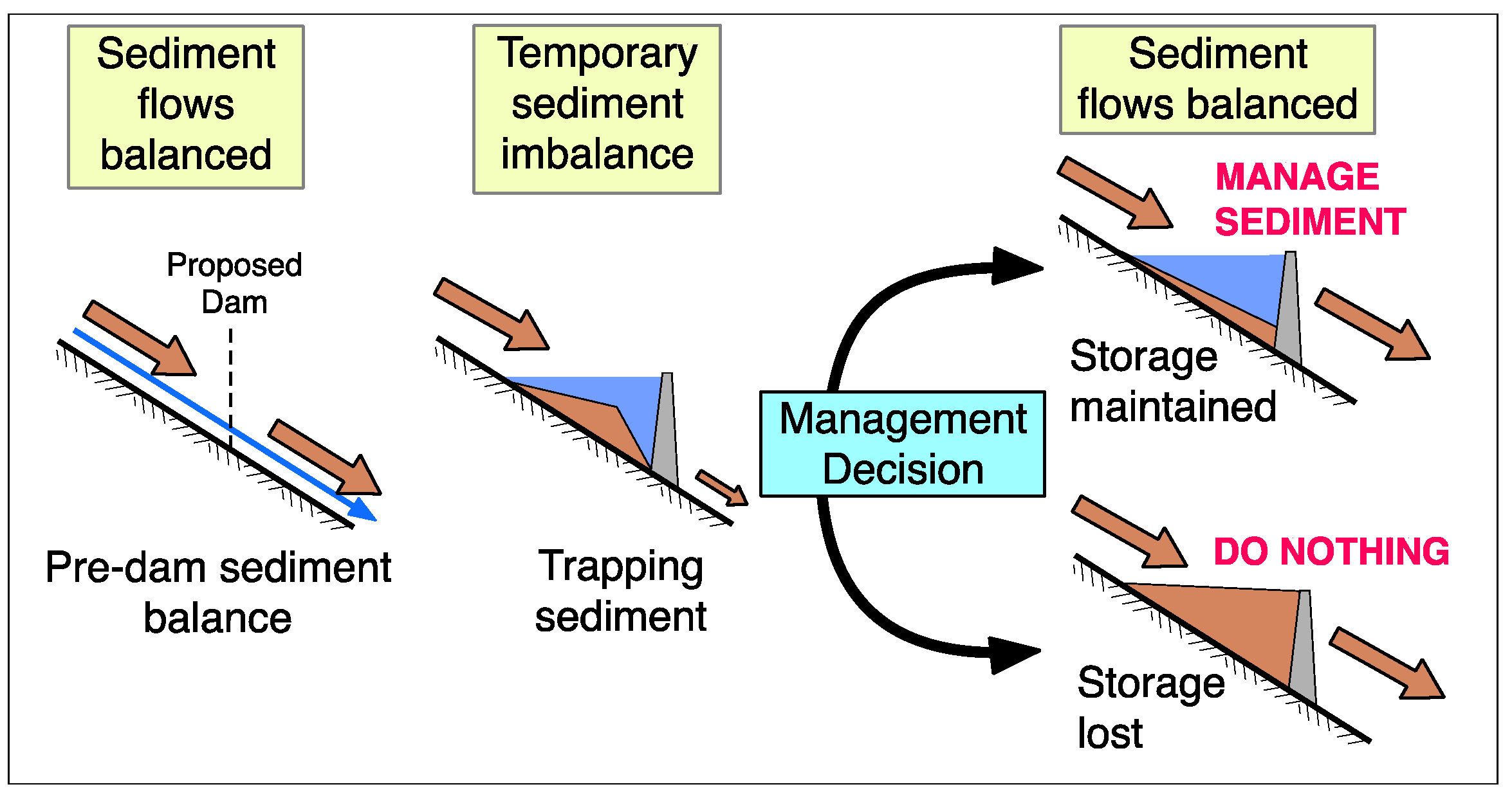
Figure 1. Alternative transitions from pre-impoundment to post-impoundment sediment equilibrium. To maintain long-term reservoir storage is a management decision.
Water 12 00861 g001
Figure 2. Classification of strategies for managing reservoir sedimentation and its consequences, using flow lines to show categories and subcategories.
Water 12 00861 g002
Figure 3. Sketches for sediment routing strategies listed in Table 1. See text for explanation. (a) Offstream Reservoir. (b) Flood Bypass. (c) Vent Turbid Density Currents. (d) Drawdown Sluicing. (e) Compartmented Reservoir.
Water 12 00861 g003
Figure 4. Sediment bypass configurations showing distinctive characteristics of each.
Water 12 00861 g004
Figure 5. (a) Photo of the entrance to the bypass tunnel at Asahi pumped storage reservoir, Japan, with diversion weir on left. (b) Sediment bypass behavior showing discharge of bed material only at lower flows when the tunnel entrance is not submerged and scouring velocities are developed across the deposit surface (redrawn from [52]).
Water 12 00861 g005
Figure 6. Bypass arrangement for Miwa dam, Japan (redrawn from [57]).
Water 12 00861 g006
Figure 7. (a) At peaking run-of-river hydropower plants, use of type-C sediment bypass tunnel together with flushing allows the reservoir to operate as a desander during the monsoon and as a power peaking pool during the dry season. (b) Section through SBT inlet with flow guide and weir.
Water 12 00861 g007
Figure 8. Photograph of the plunge line for a turbid density current entering Nurek reservoir on Vakhsh River, Tajikistan. Flow is toward the left. (photo by author).
Water 12 00861 g008
Figure 9. Aspiration of turbidity current into a higher level outlet tunnel with an “elephant trunk” flow guide—Zengwen reservoir, Taiwan (redrawn from site visit handout).
Water 12 00861 g009
Figure 10. (a,b) Pressure flushing scour cone configuration based on physical modeling (modified from [65]). (c) Scour cone at outlet of sedimented reservoir on Río San Antonio, Minas, Gerais, Brazil. (photo by author).
Water 12 00861 g010
Figure 11. Reservoir flushing sequence.
Water 12 00861 g011
Figure 12. Geometry of scour channel that can be sustained by either flushing or sluicing.
Water 12 00861 g012
Figure 13. (a) Advance of reservoir delta with constant minimum operating level, La Esmeralda reservoir, Colombia. (b) By increasing the minimum operating level, sediment deposits are focused onto the top of the delta rather than on the forward face, Tarbela reservoir, Pakistan.
Water 12 00861 g013
Table 1. Sediment Routing Strategies to Separate Flows of Clear and Muddy Water.
StrategyManagement Strategy
SEDIMENT BYPASS:
(a) Offstream ReservoirDivert clear water (normal flows) into storage
(b) Flood BypassDivert muddy water (flood flows) around storage
SEDIMENT PASS-THROUGH:
(c) Vent Turbid Density CurrentsVertical separation of clear and muddy flows
(d) Drawdown SluicingTimewise separation of clear and muddy flows
(e) Compartmented ReservoirHorizontal separation of clear and muddy flows
Table 2. Operating Strategy for Bypass around Sedimentation Headpond.
InflowOperation
Inflow < Turbine design flowBypass does not operate
Inflow > Turbine design flowBypass all inflow exceeding turbine design flow
Inflow = Flushing flow triggerOutlets at dam opened for empty flushing of reservoir
Table 3. Differentiation between Sluicing and Flushing.
ParameterSluicingFlushing
TimingAlways coincides with natural flood flowsMay not coincide with large natural floods, may have pre-determined dates
Outlet capacityCan pass large floods with minimum backwaterDischarge and drawdown may be limited by low-level outlet capacity
Sediment dischargeSediment outflow ≈ inflowSediment outflow >> inflow
Reservoir intakesMay operate during sluicing periods, if so designedCannot operate (concentration too high, water level too low)
Recover lost capacityPrimarily intra-annual depositsYes
Redeposition in downstream channelLittle significance due to high discharge (flood)Significant, post-flushing clear water release may be needed
Typical erosion patternRetrogressive erosion not typicalRetrogressive erosion may occur
Extreme spike in sediment concentrationExtreme concentrations avoidedHigh peak concentration occurs when full drawdown level is reached
Table 4. Adaptive Strategies Responding to Sedimentation Impacts.
Adaptive StrategyDescription
1. Focus or redistribute sedimentsOperate pool levels to manipulate the geometry of delta deposits, especially to retard movement of the delta toward intakes.
2. Increase storageRaise dam or build new storage or supply project elsewhere.
3. Improve operational efficiencyOptimize operation to maximize benefits from declining storage volume. May involve pool re-allocation, operational optimization, conjunctive use with groundwater and similar strategies.
4. Modify infrastructureModify sediment-sensitive infrastructure to accommodate increasing sediment loads or encroachment by sediment deposits.
5. Decrease delivery of benefitsUsers adapt to reduced water supply or other benefits through conservation, abandoning low-value water-intensive activities, etc.
6. Re-purpose or decommissionReservoir no longer serves intended purposes and is permanently removed from operation. Dam may be removed. Reservoir area may be repurposed (e.g., aggregate mining, wildlife sanctuary).