Article

Numerical Solution of the Two-Dimensional Richards Equation Using Alternate Splitting Methods for Dimensional Decomposition

by
Dariusz Gąsiorowski
and
Tomasz Kolerski
*
Faculty of Civil and Environmental Engineering, Gdańsk University of Technology, Narutowicza 11/12, 80-233 Gdańsk, Poland
*
Author to whom correspondence should be addressed.
Water 2020, 12(6), 1780; https://doi.org/10.3390/w12061780
Submission received: 15 May 2020 / Revised: 8 June 2020 / Accepted: 20 June 2020 / Published: 23 June 2020
(This article belongs to the Section Hydrology)

Abstract

:
Research on seepage flow in the vadose zone has largely been driven by engineering and environmental problems affecting many fields of geotechnics, hydrology, and agricultural science. Mathematical modeling of the subsurface flow under unsaturated conditions is an essential part of water resource management and planning. In order to determine such subsurface flow, the two-dimensional (2D) Richards equation can be used. However, the computation process is often hampered by a high spatial resolution and long simulation period as well as the non-linearity of the equation. A new highly efficient and accurate method for solving the 2D Richards equation has been proposed in the paper. The developed algorithm is based on dimensional splitting, the result of which means that 1D equations can be solved more efficiently than as is the case with unsplit 2D algorithms. Moreover, such a splitting approach allows any algorithm to be used for space as well as time approximation, which in turn increases the accuracy of the numerical solution. The robustness and advantages of the proposed algorithms have been proven by two numerical tests representing typical engineering problems and performed for typical properties of soil.

1. Introduction

The subsurface flow under unsaturated conditions can be described by the Richards equation, whose numerical solution in the case of two-dimensional (2D) or three-dimensional (3D) problems is still not a trivial task [1]. This problem becomes especially significant when a large computational domain with a high spatial resolution and long simulation period is required. The difficulties are also enhanced by the strong non-linearity of the constitutive relations describing the hydraulic properties of porous media [2].
For solving the 2D and 3D Richards equations, a variety of numerical algorithms based on the finite difference (FD) [3,4,5], finite element (FE) [6,7,8], and finite volume (FV) methods [9,10,11,12] have been proposed. Among the aforementioned methods applied for solving multi-dimensional flow problems, it is necessary also to distinguish coupled algorithms, such as the control-volume FD scheme [13], the mixed FE scheme [14,15,16], and the approach based on semi-discretization, in the form of the method of lines (MoL) and transversal method of lines (TMoL) [17]. An interesting group of algorithms used to solve the Richards equation also provide the methods using the Kirchhoff transformation. Such approach for variably saturated 2D flow in layered soil has been applied by Suk and Park [18] as well as by Berninger et al. [19].
The methods based on FD are especially attractive due to their simplicity for implementation in numerical code, however, these methods are mainly limited to a regular domain. Thus, for complex 2D and 3D geometries with curvilinear boundaries, the FE and FV methods are particularly suitable with regard to their flexibility for spatial discretization. However, it is worth adding that algorithms derived for an unstructured and curvilinear grid using finite elements or volumes are often less accurate in comparison to a structured one. To eliminate the above disadvantage, the original equation posed on an irregular grid can be transformed into a problem which is solved using a computational rectangular grid. Such an approach for solving the 2D Richards equation has been proposed by Arrarás et al. [20] as well as by Deng and Wang [21].
The nature of the flow in the unsaturated zone states that while solving a given problem, a significant resolution of the spatial grid is often required. This situation is further complicated when the multi-dimensional Richards equation is considered. Then, the resulting system of algebraic equations contains a coefficient matrix with a very wide bandwidth of non-zero elements. The form of this bandwidth mainly depends on the structure of the assumed grid as well as on the numbering of nodes. It is worth adding that the bandwidth is the main factor that determines the efficiency of the numerical algorithm, in such a way that increasing the bandwidth involves a longer computational time.
In order to improve computational efficiency, the dimensional splitting method can be applied. Due to the splitting algorithm, the solution of a 2D or 3D equation at a given time step is reduced to the solution of a set of 1D equations for each of the directions of the coordinate system. Consequently, the obtained system of algebraic equations has a tri-diagonal coefficient matrix, which can be solved more efficiently than a system with a very wide bandwidth. It is worth noting that a tri-diagonal matrix can also be obtained using the method in which the 2D Richards equation is solved by the MoL in its x-direction and the TMoL in the y-direction [17].
For solving a multi-dimensional Richards equation, the dimensional splitting in the form of an alternating direction implicit (ADI) algorithm was applied by Weeks et al. [22] for unsaturated flow through inclined porous media, and by An et al. [23] for flow into layered soil. As it has been demonstrated by these authors that the solution obtained for the standard ADI method often does not converge even for a small time step. In particular, this is visible for 3D problems and partially saturated conditions [23]. For this reason, modifications of the standard ADI algorithm are required to ensure a stable solution of the Richards equation. Moreover, the family of ADI algorithms is inflexible because such splitting based on a strictly prescribed spatial and temporal approximation of each 1D equation, and consequently their applicability is limited.
To eliminate the above inconveniences during dimensional decomposition, the fractional step method, also called the Godunov method, can be applied. A fundamental description of this approach is provided by Toro [24] and LeVeque [25] for the 2D shallow water equations, whereas an application for solving the 2D diffusive wave equation is given by Gąsiorowski [26]. As a result of the splitting procedure, the obtained 1D equation for each direction can be solved by any algorithm based on the FD, FE, or VF methods. Moreover, the Godunov method is one of the most effective methods and usually leads to a solution with high accuracy when a linear problem is considered. Unfortunately, the Richards equation is highly non-linear. Consequently, dimensional splitting introduces an additional error into the numerical solution. As a result of the calculation over one time step, the obtained solutions differ from each other as well as from the corresponding unsplit or exact solution. This splitting error depends mainly on the time step and on the direction in which the calculations are started. It is worth adding that the splitting error is independent from the accuracy of the scheme applied for solving 1D equations [25]. Due to the splitting error, the Godunov method is only 1st order accurate with regard to time. In order to increase the accuracy of the splitting process, the Strang method can be used [27]. This method is 2nd order accurate, but requires about twice the amount of computational effort in comparison to the Godunov method, which significantly reduces the efficiency of the decomposition process.
In this study, in order to overcome the abovementioned flaws, we applied the modified Strang method as well as deriving an alternate splitting algorithm. The modification is performed by appropriately changing the sequence for a time integration. As a result, the efficiency of the modified method is very similar to that obtained with the Godunov method and at the same time the adequate accuracy of the numerical solution is ensured.

2. Richards Equation

In hydrological application, the Richards equation is often considered in a mixed form, which takes into account the water content and the water pressure head [11]. Such a form of equation is mass-conservative and for the 2D flow it can be written as follows:
θ t = z K z h h z K z h + x K x h h x ,  
where θ(h) is volumetric water content, (-); h is pressure head (negative for the unsaturated zone), (m); t is time, (s); x, z are spatial variables, (m); and Kx(h) and Kz(h) are unsaturated hydraulic conductivity in x and z direction, respectively, (m·s−1).
The first and second terms on the right side of Equation (1) are associated with diffusion transport due to capillarity, while the third term represents advective transport resulting from gravity. The Richards equation must be completed with the relationship between the pressure head, water content, and hydraulic conductivity, describing the hydraulic properties of the porous media. For this purpose, the Mualem–van Genuchten functions [28,29] can be applied:
S e = θ θ r θ s θ r = 1 + α h n m
K h = K s S e 0.5 1 1 S e 1 / m m 2
C h = θ h = α n m θ s θ r α h n 1 1 + α h n m + 1
where Se is effective saturation, (-); 0 ≤ Se ≤ 1, K(h) is hydraulic conductivity, (m·s−1); C(h) is specific capacity, (m−1); Ks is saturated hydraulic conductivity, (m·s−1); θs and θr are saturated and residual water content, respectively, (-); α is the parameter related to the average pore size, (m−1); and n and m are dimensionless parameters related to pore size distribution, m = 1 − 1/n, (-).
The hydraulic conductivity can be also described using the exponential function in the form of Gardner relation as follows [18,30]:
K h = K s exp h h g
where hg is a scaling parameter. According to the assumed Gardner relation, the effective saturation and specific capacity take the following forms [18]:
S e = θ θ r θ s θ r = exp h h g
C h = θ h = θ s θ r h g exp h h g
For such constitutive functions (Equations (5)–(7)), an exact solution of the Richards equation has been derived for the case of 2D as well as 3D [31].

3. Splitting Methods for Dimensional Decomposition

In order to perform the dimensional splitting, the Richards equation (Equation (1)) can be rewritten to the following operator form:
θ t = A + B h ,
where the differential operators A and B correspond to the terms in z and x directions, respectively. Assuming flow in an isotropic soil, these operators are expressed as:
A = z K z z K z ,
B = x K x x .
Equation (8) can be considered as a general form of 2D Richards equation, where the constitutive function describing the hydraulic conductivity and other relations take the appropriate form depending on the assumed model, i.e., the Mualem–van Genuchten, the exponential or the Brooks–Corey model [32].

3.1. Godunov Method

At first, let us consider the simplest splitting algorithm, in the form of the Godunov method. To this order, the spatial domain is overlaid with a rectangular mesh with N rows and M columns giving the total of M × N nodes (Figure 1). According to the Godunov approach, over each time step the Richards equation (Equation (8)) can be rewritten as an equivalent sequence of the two following equations:
θ ( 1 ) t = A h ( 1 )       over   Δ t   for   j = 1 , , N
θ ( 2 ) t = B h ( 2 )       over   Δ t   for   i = 1 , , M .
where (1) and (2) are superscripts indicating the stage in directions z and x, respectively; Δt is the time step; i and j are node indices with regard to directions z and x, respectively; and M and N are the number of nodes with regard to directions z and x, respectively.
As a result, the splitting process is carried out in two stages using 1D equations. In the first stage, Equation (11) is solved in the z direction over the time step Δt with the initial condition h(1)(x,z,t) = h0. The procedure is performed for the consecutive rows j = 1, 2, …, N (see Figure 1a). Then, using the obtained results as the initial condition h(2)(x,z,t) = h(1)(x,z,t + Δt) in the second stage, Equation (12) is solved for x direction also over the time step Δt. In this case, the calculations are performed with the consecutive columns i = 1, 2, …, M (Figure 1b). After the last stage, the values of the pressure head at the time level t + Δt are obtained, i.e., h(x,z,t + Δt) =h(2)(x,z,t + Δt).
Since the Richards equation is non-linear, the dimensional decomposition applied to its solution introduces a splitting error. As a result of the accuracy analysis, the Godunov method is only 1st order accurate with respect to the time. Consequently, in this case, the splitting error takes the following form [25]:
E = Δ t 2 2 A B B A h 0 + O ( Δ t 3 )
where Ot3) denotes the higher terms omitted in the Taylor series expansion. As can be seen, the splitting error depends mainly on the value of the time step Δt as well as on the relation between the differential operators A and B. When the operator multiplication, i.e., product AB is equal to BA, then the applied method leads to a 2nd order accurate solution. This case takes place for the linear problem. However, with regard to the high non-linearity of the Richards equation, the operator multiplications differ from each other (AB≠BA). As a consequence, this introduces the splitting error, which decreases an accuracy of the final solution.

3.2. Standard and Modified Strang Method

In order to eliminate or to minimize the splitting error, the Strang method can be applied for the dimensional splitting [27]. Using this method, the decomposition process is carried out in three stages, such that the 2D Richards equation (Equation (8)) is decomposed into the following set of 1D equations:
θ ( 1 ) t = A h ( 1 )       over   Δ t / 2   for   j = 1 , , N
θ ( 2 ) t = B h ( 2 )       over   Δ t   for   i = 1 , , M
θ ( 3 ) t = A h ( 3 )       over   Δ t / 2   for   j = 1 , , N
Similarly, as it was presented for the Godunov method, the corresponding calculations are performed using the grid presented in Figure 1. At the first stage, the subproblem in z direction (Equation (14)) is solved over a half time step of the length Δt/2 with the initial condition h(x,z,t) = h0. The solution of this stage h(1)(x,z,t + Δt/2) is used as the initial condition at the second stage for the solution of Equation (15) in x direction over a full time step Δt. Finally, at the third stage, Equation (16) is integrated for another half time interval Δt/2 again in z direction with the initial condition h(3)(x,z,t) = h(2)(x,z,t + Δt). After the last stage at the time level t + Δt, the solution h(x,z,t + Δt) = h(3)(x,z,t + Δt) is obtained. A schematic sketch of the Strang algorithm is shown in Figure 2a.
The Strang method is 2nd order accurate with respect to the exact solution. Consequently, this method ensures a solution with a smaller splitting error than the Godunov method, even if the operator multiplications (AB or BA) differ from each other. However, while increasing accuracy up to the 2nd order by using the Strang method, at the same time, the computational efficiency of this method is significantly reduced in comparison with the sequential Godunov method (Equations (11)–(12)). As it is easy to check, the Strang method requires approximately 50% more calculations (with stages S = 3NT, where NT is the number of time steps) than the 1st order Godunov method (with stages S = 2NT). Considering a reduction of computational work, Strang [27] proposed a modification of the algorithm in such a way that it becomes more effective while simultaneously maintaining 2nd order accuracy. In order to examine the introduced modification, let us consider the solution of the original equation (Equation (8)) at time t + Δt using an unsplit method. This solution can be rewritten in the form [25,33]:
h ( x , z , t + Δ t ) = e Δ t A + B h 0
Similarly, one can rewrite the solution for the Strang method:
h ( x , z , t + Δ t ) = e 0.5 Δ t A e Δ t B e 0.5 Δ t A h 0
and for the Godunov method:
h ( x , z , t + Δ t ) = e Δ t A e Δ t B h 0
Strang observed [27], that while solving the differential equation on a time period (0, T), the calculations are usually not performed for a single large step Δt, but for many steps that are systematically added up and lead to the total period of time T. As a consequence, applying the Strang method for NT steps (so that NT ·Δt =T) we obtain the following solution [25]:
h T = e 0.5 Δ t A e Δ t B e 0.5 Δ t A e 0.5 Δ t A e Δ t B e 0.5 Δ t A e 0.5 Δ t A e Δ t B e 0.5 Δ t A h 0
Then using the substitutions e 0.5 Δ t A e 0.5 Δ t A = e Δ t A the final solution can be rewritten as follows:
h T = e 0.5 Δ t A e Δ t B e Δ t A e Δ t B e Δ t A e Δ t B e 0.5 Δ t A h 0
As it can be seen, due to this modification, the sequence of integration is performed with a full time step Δt for A and B operators. Only at the beginning as well as at the end of the period T, the algorithm is executed with a half time step (Figure 2b). These observations allow the construction of the modified Strang method, which, applied to the directional splitting of the 2D Richards equation, leads to the following sequence of calculations:
θ ( 1 ) t = A h ( 1 )       over   Δ t / 2   for   j = 1 , , N
θ ( 2 ) t = B h ( 2 )       over   Δ t   for   i = 1 , , M
θ ( 3 ) t = A h ( 3 )       over   Δ t   for   j = 1 , , N
θ ( S 1 ) t = B h ( S 1 )       over   Δ t   for   i = 1 , , M
θ ( S ) t = A h ( S )       over   Δ t / 2   for   j = 1 , , N
where the total number of stages S corresponding to the number of time steps NT can be calculated by the following relation:
S = 2 N T 1 + 3
Figure 3 shows the computational efficiency for the Strang splitting methods with respect to the number of time steps NT. To this purpose, the relative increase of the computational effort with reference to the Godunov method was estimated using the following formula:
C E = 100 S S r e f S r e f
where Sref is the number of stages performed using the Godunov method (S = 2NT), while S is the number of stages for the standard Strang method (S = 3NT) or for the modified Strang method (S according to Equation (27)).
As illustrated in Figure 3, the standard Strang method requires 50% more calculations than the Godunov method, while the modified Strang method yields a slight increase in the calculation effort (25%) only at the initial calculation period, and it quickly decreases to 5% after 10 time steps. A further increase in efficiency is approximately asymptotic and after 50 steps the growth of computational effort reaches a value below 1.0%.

3.3. Alternate Splitting Method

As it can be seen, the modified Strang method differs from the Godunov splitting method only due to the fact that at the beginning and at the end of the computational period T, the algorithm is executed with a half time step (Figure 2b). Moreover, an appropriate result can be expected with the application of the modified Strang method if the time step is constant. However, in practical applications, the Richards equation is solved using algorithms with a variable time step, usually taking very small values (even about 10−5 s) at the beginning of the simulation. Consequently, in such conditions, the solution obtained by means of the modified Strang method will converge to a solution with the accuracy obtained using the Godunov method. For this reason, an alternate modified algorithm for dimensional splitting is proposed. Based on the modification of splitting for the Strang method, it seems that an increase in accuracy can be achieved by successively reversing the order of integration at each time stage (Figure 4), according to the following algorithm:
θ ( 1 ) t = A h ( 1 )       over   Δ t   for   j = 1 , , N
θ ( 2 ) t = B h ( 2 )       over   Δ t   for   i = 1 , , M
θ ( 3 ) t = B h ( 3 )       over   Δ t   for   i = 1 , , M
θ ( 4 ) t = A h ( 4 )       over   Δ t   for   j = 1 , , N
θ ( 5 ) t = A h ( 5 )       over   Δ t   for   j = 1 , , N
θ ( S 1 ) t = B h ( S 1 )       over   Δ t   for   i = 1 , , M
θ ( S ) t = A h ( S )       over   Δ t   for   j = 1 , , N
It follows from the above formulations that at a given time level (t = n·Δt), the calculations start in direction z (operator A), while at the next time level (t = (n + 1)·Δt) the reverse sequence is performed starting in direction x (operator B). All integrations are carried out with the full time step Δt, and consequently, the computational efficiency corresponds to that obtained with the Godunov method. It is worth noting that such a sequence of calculations is valid for the appropriate number of time steps NT corresponding to an even number of stages S performed over the total simulation period T.

4. Solution of 1D Equations
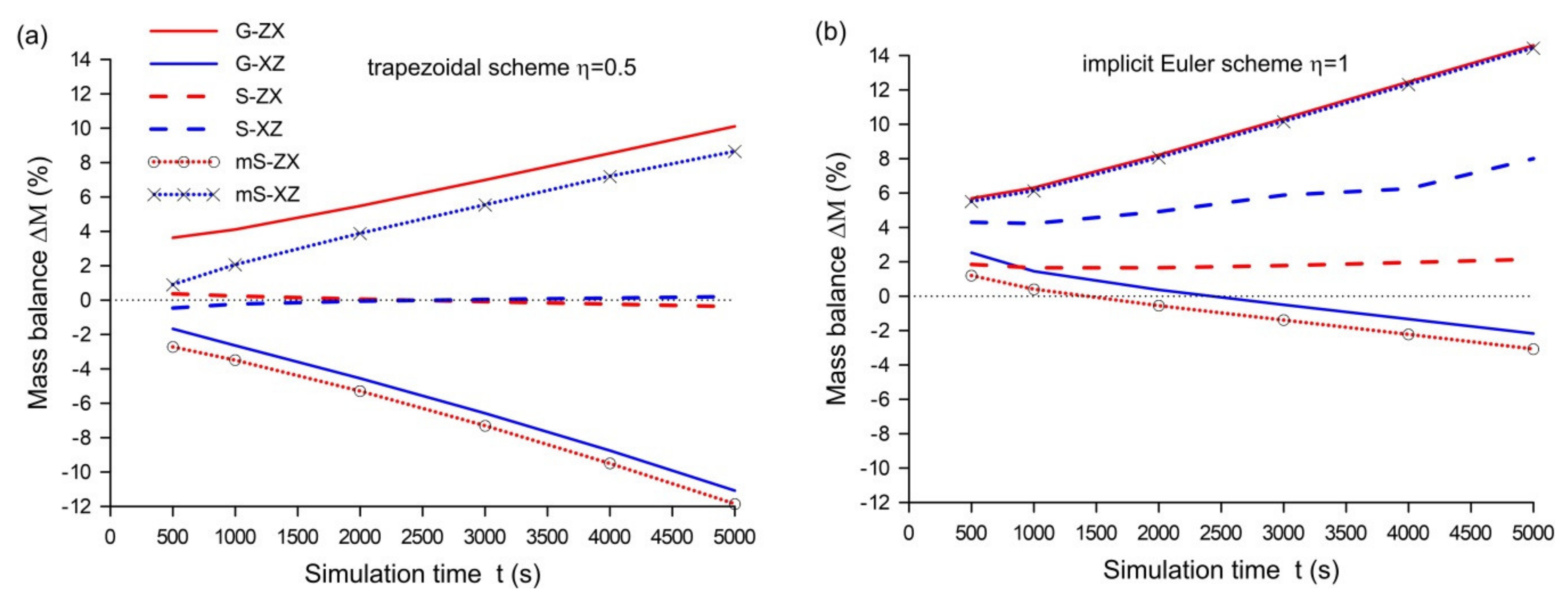
The specificity of the proposed method used for dimensional decomposition allows the obtained 1D equation to be solved by means of any algorithm based on the FD, FE, or FV methods. In this study, for spatial approximation, the FD method is applied using a combination of backward and forward differences for the diffusion term while using a forward difference for the advection term when an equation in z direction is approximated. Due to the spatial discretization, the partial differential equation is reduced to a system of time-dependent ordinary differential equations (ODE). For this reason, the obtained ODE is solved using the two-level implicit scheme [34,35]. Finally, as a result of the spatial and temporal approximation, the following FD scheme corresponding to the 1D Richards equation in z direction (Equation (11)) is obtained:
θ i n + 1 θ i n Δ t + 1 η K ¯ i 1 / 2 n ( h i n h i 1 n ) Δ z 2 K ¯ i + 1 / 2 ( h i + 1 n h i n ) Δ z 2 + b ( K i + 1 n K i n ) Δ z + + η K ¯ i 1 / 2 n + 1 ( h i n + 1 h i 1 n + 1 ) Δ z 2 K ¯ i + 1 / 2 ( h i + 1 n + 1 h i n + 1 ) Δ z 2 + b ( K i + 1 n + 1 K i n + 1 ) Δ z = 0
where i is the index of the internal node; i = 2, 3,..., M−1,M is the total number of nodes; n is the index of the time level; Δz is the space step; Δt is the time step; θ i n is the nodal value of the water content; h i n is the nodal value of the pressure head; K i n is the nodal value of hydraulic conductivity; K ¯ i + 1 / 2 n is the nodal value of hydraulic conductivity averaged using the arithmetic mean [36,37,38], K ¯ i + 1 / 2 n = 0.5 K i + K i + 1 ; b is a parameter; b = 1 if the advection term is incorporated into the equation for z direction, otherwise b = 0; and η is the weighting parameter ranging from 0 to 1.
In Equation (36), the weighting parameter η determines the stability and accuracy of the numerical scheme [35]. Its particular value gives a well-known algorithm used for the solution of ODE. For η = 1, Equation (36) corresponds to the implicit Euler (backward) scheme, which is usually used in the case of the Richards equation. Such an approximation of the time derivative is of the 1st order of accuracy, and consequently, the numerical diffusion can cause excessive smoothing of the propagating front in the final solution [36,38]. For η = 1/2, Equation (36) becomes the implicit trapezoidal scheme (also known as the Crank–Nicholson scheme), which ensures an approximation with the 2nd order of accuracy when a linear equation is considered. However, the trapezoidal scheme can generate numerical oscillations, which lead to instabilities.
The system of algebraic equations (Equation (36) for i = 2,3,…,M−1) is non-linear. For its solution, Celia et al. [39] proposed the modified Picard algorithm, which minimizes the mass balance error. According to this method, a nodal value of the water content at the next time n + 1 and iteration k + 1 is approximated using the following formula:
θ i n + 1 , k + 1 = θ i n + 1 , k + C i n + 1 , k h i n + 1 , k + 1 h i n + 1 , k
where n is the time level index; k is the iteration index; Cin+1,k is the nodal value of specific capacity. Using the above approximation, the modified Picard scheme applied to Equation (36) gives the following algebraic non-linear equation:
η Δ t Δ z 2 K ¯ i 1 / 2 n + 1 , k Δ h i 1 n + 1 , k + η Δ t Δ z 2 K ¯ 1 1 / 2 n + 1 , k + K ¯ i + 1 / 2 n + 1 , k + C i n + 1 , k Δ h i n + 1 , k + 1 η Δ t Δ z 2 K ¯ i + 1 / 2 n + 1 , k Δ h i + 1 n + 1 , k = f i k
where Δ h n + 1 , k + 1 is the correction of the pressure head, Δ h n + 1 , k + 1 = h n + 1 , k + 1 h n + 1 , k ; and f i k is the right side term at the kth iteration described as follows:
f i k = 1 η Δ t Δ z 2 K ¯ i 1 / 2 n h i 1 n K ¯ i 1 / 2 n + K ¯ i + 1 / 2 n h i n + K ¯ i + 1 / 2 n h i + 1 n b Δ z K i + 1 n K i n + θ i n η Δ t Δ z 2 K ¯ i 1 / 2 n + 1 , k h i 1 n + 1 , k K ¯ i 1 / 2 n + 1 , k + K ¯ i + 1 / 2 n + 1 , k h i n + 1 , k + K ¯ i + 1 / 2 n + 1 , k h i + 1 n + 1 , k b Δ z K i + 1 n + 1 K i n + 1 θ i n + 1 , k
Equation (38), written for each node i = 2, 3,…, M−1 and completed with boundary conditions, can be expressed using the matrix notation:
D k Δ h k + 1 = F k
where D is the tri-diagonal matrix of the size M × M; Δ h k + 1 is the correction vector, Δ h k + 1 = h n + 1 , k + 1 h n + 1 , k ; h = h 1 , , h i , h i 1 , , h M T is the vector of nodal pressure head values; and F = f 1 , , f i , f i 1 , , f M T is the vector with components described using Equation (39). While solving the set of non-linear equations (Equation (40)), the iteration process is continued until the following criterion of convergence is satisfied for all nodes:
h i n + 1 , k + 1 h i n + 1 , k = Δ h i n + 1 , k + 1 ε
where ε is the convergence tolerance, whose value is specified.
The presented procedure is repeated for each column j (where j = 1, 2,…, N), so that to obtain a solution for whole domain in z direction. The same algorithm is also applied for the 1D equations in x direction (Equation (12)) for each row i (where i = 1, 2,…, M). For this reason, in Equation (38), index i and space interval Δz are replaced with j and Δx, respectively, while the matrix D is of dimension N × N. Moreover, since an advective term vanishes for the equation in x direction, parameter b is equal to 0.
In order to improve the computational efficiency, the time step is frequently adjusted according to the current number of iterations performed with the iterative procedure. For this reason, the following algorithm can be used [6,11]:
Δ t = Δ t f r if N i t e r > N m a x Δ t f m if N i t e r < N m i n
Thus, if the number of iterations Niter for ensuring convergence at each time level is higher than the predetermined maximal value Nmax, then the time step is reduced by the factor fr < 1. On the other hand, when the number of iterations is less than Nmin, then the time step is multiplied by the factor fm > 1. Usually, satisfactory results for different flow conditions are obtained with Nmin = 3, Nmax = 7, fr = 0.6–0.85, and fm = 1.1–1.25 [11,23].

5. Numerical Tests

For evaluating the splitting algorithms, two numerical tests have been performed where infiltration into dry isotropic soil is considered. In order to check the accuracy of different splitting strategies, the numerical solutions are compared to an exact solution or the reference solution computed for a refined computational grid with significantly smaller spatial and time steps. A comparison is performed in terms of the root mean square (RMS) error computed at the end of the simulation. This error is defined as follows:
R M S = 1 M i = 1 M h i h i r e f 2
where RMS is the root mean square error calculated at the final simulation time T; hi is the calculated nodal value of the pressure head at time T; h i r e f is the reference or exact nodal value of the pressure head at time T; and M is the number of nodes.
The obtained results are also checked with regard to the mass conservation principle. In this study, the relative mass balance error is used in the following form:
Δ M = 1 V T V 0 F b 100
where ΔM is the relative mass balance error; and VT and V0 are the total final (at time t = T) and total initial (at time t = 0) amount of water in the domain given by the formulas:
V T = A θ x , y , t = T d x d z ,
V 0 = A θ x , y , t = 0 d x d z ,
where Fb is the total net flux through the boundaries of the domain:
F b = t = 0 t = T K z h z z 1 + K x h x x 1 d t
Moreover, in the study, the computational efficiency is evaluated based on the total number of iterations Niter performed during the simulation time T. It is worth adding that the efficiency depends on many factors. For example, the efficiency can be increased by increasing the time step or/and spatial step. Consequently, changing the time step and the resolution of the grid, at the same time also affects the accuracy of the final solution. For this reason, it seems that the computational efficiency should be evaluated using both the total number of iterations (or the computational time) and the accuracy of the solution [40,41]. In this study, for the estimation of the computational efficiency, the following formula is proposed:
E f = 1 R M S N i t e r
where Ef is the computational efficiency; RMS is the solution accuracy calculated using the RMS error (Equation (43)); and Niter is the total number of iterations NT.

5.1. Test 1—Simulation of Infiltration Using the Gardner Model

In the first test, the hydraulic properties in the Richards equation are described using the Gardner functions given by Equations (5)–(7) with the following parameters: residual water content θr = 0.15, saturated water content θs = 0.45, saturated hydraulic conductivity Ks = 10−5 m/s, and scaling parameter hg = 2 m. The calculations are performed for the rectangular domain with the dimensions Lx = 1 m and Lz = 2.5 m. At the top of the domain for z = 0 as a boundary condition, the following distribution of the pressure head is imposed:
h x , z = 0 , t = ln exp h b h g + 1 exp h b h g sin π x L x
Thus, the pressure head on the top is equal to zero in the center (Lx/2, Lz/2) and decreases to the value hb on the left (x = 0, z = 0) and right (x = Lx, z = 0) edges (Figure 5a). On all boundaries of the domain, a constant pressure head is assumed: h(x = 0, z)= h(x = Lx, z)= h(x, z = Lz) = hb = −10 m. The initial condition at the time t = 0 corresponds to a uniform distribution of the pressure head for the whole domain and is specified as h(x,z,t = 0) = h0= −10 m. For such initial−boundary conditions, the analytical solution of the 2D Richards equation has the following form [31]:
h r e f x , z , t = h g ln exp h b h g + 1 exp h b h g sin π x L x exp L z z 2 h g sinh β z sinh β L z + 2 L z c k = 1 1 k λ γ sin λ z exp γ t
where
β = 1 4 h g 2 + π L x 2 ,   c = θ s θ r h g K s ,   λ = k π L z ,   γ = β 2 + λ 2 c .
Numerical tests were performed for a grid with a constant spatial length Δx = Δy = 0.025 m. The analytical solution was compared with the results obtained using dimensional splitting algorithms in the form of the Godunov method (G), Equations (11)–(12); the Strang method (S), Equations (14)–(16); and the modified Strang method (mS), Equations (22)–(26). The calculations were carried out for two variants, depending on the sequence in which the 1D equations are solved at each time level. In the first variant, at the initial stage, the calculation always starts with z direction (ZX), while for the second variant, a reverse sequence is performed with the initial stage in x direction (XZ). Simulations were driven for two values of the weighting parameter: η = 0.5 (the implicit trapezoidal scheme) and η = 1 (the implicit Euler scheme) in the FD scheme (Equation (36)) and using a constant time step Δt equal to 5, 10, 20, 40, and 50 s. While solving the system of non-linear algebraic equations, the tolerance of the iterative process ε was set to 0.001 m (Equation (41)). Such assumed value of tolerance ensures high accuracy while maintaining the number of iterations at an appropriate level usually not exceeding twenty iterations at a given time step.
A graphical illustration of the results calculated at the end of the simulation T = 1000 s is presented in Figure 5 and Figure 6. Figure 5a displays the pressure head distribution in the form of a contour map obtained for the exact solution, whereas in Figure 5b–d, the corresponding isolines of water pressure, calculated using various splitting methods with the time step Δt = 50 s, are compared with the exact solution. Moreover, in Figure 6, the water saturation profiles along the vertical z direction at the cross-section x = 0.5 are presented.
It is apparent that the Godunov splitting method (Figure 5b and Figure 6b) reproduces solutions where the position of the wetting–drying front is underestimated (G-ZX) or overestimated (G-XZ), depending on the sequence of calculations. The difference between the exact and numerical solutions is the largest for the calculations performed with the sequence XZ. The best results are obtained with the sequence ZX for both the standard (Figure 5c and Figure 6b) and the modified Strang method (Figure 5d). The calculations performed with the sequence XZ result in a greater deviation from the exact solution, but in this case, the difference is smaller than for the Godunov splitting method. It seems that the discrepancy between the results obtained with the ZX and XZ sequences is caused by the fact that the 1D Richards equations after dimensional decomposition differ by the advection term resulting from gravity. Consequently, while splitting, the final result depends on the sequence in which the 1D equations are numerically integrated.
The above results are also confirmed by the accuracy analysis in terms of the RMS errors presented in Figure 7. RMS errors are calculated using the solutions along the axis z at the cross-section x = 0.5 m obtained for various constant time steps Δt equal to 5, 10, 20, 40, and 50 s. Moreover, the RMS error analysis is carried out for the solutions obtained using the implicit trapezoidal scheme with the weighting parameter η = 0.5 (Figure 7a) and the implicit Euler scheme with η = 1 (Figure 7b).
As one can see, increasing the time step Δt causes growth of the RMS errors. The splitting based on the Godunov method takes significantly greater values in RMS error (about 3 times more for Δt = 50 s) than the Strang method. The values of the RMS errors also depend on the direction in which the calculations are initiated. If the splitting for the Strang methods starts with z direction (S-ZX and mS-ZX), then the solution leads to the best result with regard to the RMS error than in the solution performed with the opposite sequence of calculations starting with x direction (S-XZ and mS-XZ). Moreover, the standard and modified Strang splitting methods give very similar values of RMS errors if the trapezoidal scheme is applied (Figure 7a). The obtained results indicate that the Strang method and its modification are approximations of the 2nd order of accuracy and they minimize the splitting error when dimensional decomposition is applied for the Richards equation. However, when the implicit Euler scheme with η = 1 is used (Figure 7b), the solutions are burdened with a higher RMS error, and the consistency between the standard and modified Strang splitting methods is also not observed, as was the case for the solution with η = 0.5. These results confirm that in addition to the appropriate splitting technique, the accuracy of the resulting solution is also affected by the choice of the time integration scheme for solving ODE. The applied trapezoidal scheme is an approximation of the 2nd order of accuracy (with respect to the time) and, combined with the Strang methods, leads to the best results. While the implicit Euler algorithm, in conjunction with the Godunov splitting method, ensures only the 1st order of accuracy leading to a worse solution.
Figure 8 presents the time evolution of the mass balance error. It is apparent that for the solution obtained using the standard Strang method with the weighting parameter η = 0.5 (Figure 8a), the mass principle is satisfied regardless of the simulation time t (the errors ΔM are less than 0.5%). Unfortunately, other splitting algorithms do not satisfy the mass conservation principle, because the mass balance errors systematically increase during the simulation time, reaching even several percent. In these cases, the mass balance error takes a negative or positive value depending on the sequence of computations. In Figure 8b, the results for the solution with the implicit Euler scheme (η = 1) are presented. As it can be seen, the mass balance values significantly differ from those obtained for the trapezoidal scheme. Thus, this test shows that besides the method of dimensional splitting, the time integration scheme also determines the mass conservation property. Since the implicit Euler scheme is the 1st order of accuracy, it generates a numerical diffusion which causes an additional deviation of the mass balance in a non-conservative algorithm. It is worth adding that this effect is also observed in other solutions of non-linear equations such as the kinematic wave equations or the shallow water equations, which are written in a non-conservative form [26,42].
The next calculations were carried out to check the efficiency of the splitting algorithms. In Figure 9a, the dependence of the number of iterations Niter on the time step is presented. This experiment confirms the earlier conclusions that the standard Strang method requires a greater number of time steps (and therefore number of iterations) than the Godunov method as well as the modified Strang method. It is also worth noting that for the modified Strang method, the number iterations necessary to achieve a convergence also depends on the sequence of splitting. However, when the accuracy of the solution is also taken into account for the estimation of computational efficiency (according to Equation (48)), the Godunov method is less effective than the Strang methods (Figure 9b). This is especially apparent for greater values of the time step Δt ≥ 20 s. The best results with regard to such computational efficiency were achieved by means of the modified and standard Strang methods with the sequence ZX of calculations.

5.2. Test 2—Simulation of Infiltration Using the Mualem–van Genuchten Model

In this case, a solution of the 2D Richards equation with the Mualem–van Genuchten functions is considered. The calculations are performed for typical properties of sand and loam presented by Carsel and Parrish [43] (Table 1). The computational domain is rectangular with the dimensions Lx and Lz. For a part of the top boundary (0.46 <xb < 0.54 m), a constant pressure head is imposed h(xb,z = 0) = 0 m (Figure 10), while on other boundaries, the zero flux condition in the normal direction is applied. The initial condition is specified as h(x,z,t = 0) = h0= −10 m. Since this test is more challenging with regard to the reproduction of a solution containing a sharp wetting front, to ensure the appropriate accuracy as well as the efficiency of the solution, the time step is adjusted according to the procedure described by Equation (42). To this order, the predetermined values of the minimal and maximal number of iterations are generally set at Nmin = 3 and Nmax = 7, respectively. The minimal and maximal allowable values of the time step (Δtmin and Δtmax) are specified depending on the considered soil. All comparisons were performed over a fixed simulation time T. The results obtained using different splitting strategies were compared to the reference solution computed using a refined computational grid with a smaller spatial step Δx = 0.01 m and the maximal time step Δtmax = 1 s. Moreover, the convergence error ε in the iteration process was decreased from 0.001 m to a value of 0.0001 m for the reference solution. Simulations were driven using the trapezoidal scheme with η = 0.5. The values of the hydraulic parameters of the soil as well as other numerical parameters used in Test 2 are summarized in Table 1.
For each soil, the computations were performed using the Godunov method (G), Equations (11)–(12); the Strang method (S), Equations (14)–(16); and the alternate modified method (mod), Equations (29)–(35). As in the previous test, the simulations were carried out for two variants of a sequence of splitting (ZX or XZ) in which 1D equations are solved.
The results of the simulation obtained for sand and loam are presented in Figure 10, Figure 11 and Figure 12, whereas Table 2 summarizes the statistics in regards to the accuracy, mass balance, and computational efficiency. Figure 10 shows the position of wetting fronts after the simulation time T obtained using the splitting algorithms with the ZX sequence only, because the solutions for the XZ sequence are very similar with regard to graphical presentation. In order to enhance the difference between various splitting methods, the predetermined values of the minimal and maximal number of iterations is set on Nmin = 4 and Nmax = 8, respectively. Due to this treatment, the time step takes a higher value during simulation than for the values previously assumed (Nmin = 3 and Nmax = 7), and consequently, in the numerical solution, greater splitting errors are generated. As it can be seen in the case of sand (Figure 10a) as well as loam (Figure 10b), all splitting algorithms reproduce a wetting front which is slightly overestimated. However, the best result with regard to the RMS error is obtained for sand using the alternate modified method (mod-ZX and mod-XZ), while for loam, all algorithms give very similar values of the RMS errors (Table 2).
In Figure 11, the mass balance error is presented. As with the previous test, the Godunov method (G-ZX, G-XZ) reveals a low mass conservation for both the ZX and XZ sequence. In this case, the error ΔM is stabilized to the value of the order at 5% and 8% for sand and loam, respectively. While the Strang method (S-ZX, S-XZ) and alternate modified method (mod-ZX, mod-XZ) minimize the mass balance error. This is especially apparent in the case of the latter method, which substantially reduces the mass balance error ΔM to a value below 1% and 2% for sand and loam, respectively.
Figure 12 displays the number of iterations for different simulation times. The Godunov method as well as the proposed method with alternate modifications are the most effective and require about 50% less iterations than the Strang splitting method. However, considering the computational efficiency estimated according to Equation (48), the best results are obtained using the alternate modified method (Table 2). Note that with such defined efficiency, the Strang method is the least effective.

6. Conclusions

In the paper, the dimensional splitting algorithms for solving the 2D Richards equation have been presented. Due to the splitting procedure, the solution of the 2D equation is reduced to the solution of a set of 1D equations for each of the directions. Consequently, the obtained system of algebraic equations has a tri-diagonal coefficient matrix, which can be solved more efficiently than as is the case with unsplit 2D algorithms. All splitting methods presented in the study allow the use of any algorithm for space as well as time approximation, which undoubtedly is a significant advantage over the methods based on ADI algorithms.
The first of the analyzed methods, the Godunov method, generates a significant splitting error, which consequently reduces the accuracy of the obtained solution. As it was shown, this splitting method also leads to a solution with a significant mass balance error.
In order to increase the accuracy of the solution, the standard and modified Strang methods were also applied for dimensional decomposition. Due to these methods, it is possible to significantly minimize the splitting error, therefore ensuring the accuracy of the solution to the 2nd order. However, the standard Strang method is not computationally effective, while the modified Strang splitting method requires the same computational effort as the Godunov method. On the other hand, the modified Strang method does not satisfy the mass conservation principle and it can be used only when the time step is constant. Numerical experiments also indicate that solutions obtained using splitting algorithms can be overestimated or underestimated depending on the sequence in which 1D equations are solved at each time level. This effect is especially apparent for the Godunov method.
In view of the above inconveniences, an alternate splitting method has been proposed which is based on successively reversing the order of integration at each time stage. The conducted experiments showed that the proposed method ensures adequate accuracy of the solution and minimizes the mass balance error. At the same time, it is the most effective of all the analyzed splitting methods, in terms of both the number of iterations and the efficiency determined, taking into account the accuracy of the solution (Equation (48)).
In the analysis, a 2D unsaturated flow for a simple domain geometry using a rectangular grid was considered. However, the proposed splitting method can also be successfully extended to 3D flow problems. Moreover, it seems that this approach can also be used for more complex geometries on an irregular grid if a coordinate transformation method is applied.

Author Contributions

Conceptualization, D.G. and T.K.; methodology, D.G. and T.K.; software, D.G.; validation, D.G.; formal analysis, D.G.; investigation, D.G. and T.K..; writing—original draft preparation, D.G. and T.K; writing—review and editing, D.G. and T.K.; visualization, D.G.; supervision, D.G. All authors have read and agreed to the published version of the manuscript.

Funding

This research received no external funding.

Conflicts of Interest

The authors declare no conflict of interest.

References

  1. Farthing, M.W.; Ogden, F.L. Numerical solution of Richards’ equation: A review of advances and challenges. Soil Sci. Soc. Am. J. 2017, 81, 1257–1269. [Google Scholar] [CrossRef] [Green Version]
  2. List, F.; Radu, F.A. A study on iterative methods for solving Richards’ equation. Comput. Geosci. 2016, 20, 341–353. [Google Scholar] [CrossRef] [Green Version]
  3. Clement, T.P.; Wise, W.R.; Molz, F.J. A physically based, two-dimensional, finite-difference algorithm for modeling variably saturated flow. J. Hydrol. 1994, 161, 71–90. [Google Scholar] [CrossRef]
  4. Dogan, A.; Motz, L.H. Saturated-unsaturated 3D groundwater model. I: Development. J. Hydrol. Eng. 2005, 10, 492–504. [Google Scholar] [CrossRef]
  5. Spanoudaki, K.; Stamou, A.I.; Nanou-Giannarou, A. Development and verification of a 3-D integrated surface water–groundwater model. J. Hydrol. 2009, 375, 410–427. [Google Scholar] [CrossRef]
  6. Simunek, J.; Huang, K.; Van Genuchten, M.T. The SWMS_3D code for simulating water flow and solute transport in three-dimensional variably-saturated media. US Salin. Lab. Agric. Res. Serv. 1995. [Google Scholar]
  7. Castanedo, V.; Saucedo, H.; Fuentes, C. Modeling two-dimensional infiltration with constant and time-variable water depth. Water 2019, 11, 371. [Google Scholar] [CrossRef] [Green Version]
  8. Šimunek, J.; Sejna, M.; van Genuchten, M. The HYDRUS-2D Software Package for Simulating the Two-Dimensional Movement of Water, Heat, and Multiple Solutes in Variably-Saturated Media, Version 2.0; International Ground Water Modeling Center, Colorado School of Mines: Golden, Co, USA, 1999. [Google Scholar]
  9. Manzini, G.; Ferraris, S. Mass-conservative finite volume methods on 2-D unstructured grids for the Richards’ equation. Adv. Water Resour. 2004, 27, 1199–1215. [Google Scholar] [CrossRef]
  10. Rees, I.; Masters, I.; Malan, A.G.; Lewis, R.W. An edge-based finite volume scheme for saturated–unsaturated groundwater flow. Comput. Methods Appl. Mech. Eng. 2004, 193, 4741–4759. [Google Scholar] [CrossRef]
  11. Szymkiewicz, A. Modelling Water Flow in Unsaturated Porous Media: Accounting for Nonlinear Permeability and Material Heterogeneity; Springer Science & Business Media: Berlin, Germany, 2013. [Google Scholar]
  12. Svyatskiy, D.; Lipnikov, K. Second-order accurate finite volume schemes with the discrete maximum principle for solving Richards’ equation on unstructured meshes. Adv. Water Resour. 2017, 104, 114–126. [Google Scholar] [CrossRef] [Green Version]
  13. Panday, S.; Langevin, C.D.; Niswonger, R.G.; Ibaraki, M.; Hughes, J.D. MODFLOW–USG Version 1: An Unstructured Grid Version of MODFLOW for Simulating Groundwater Flow and Tightly Coupled Processes Using a Control Volume Finite-Difference Formulation; US Geological Survey: Reston, VA, USA, 2013.
  14. Bause, M.; Knabner, P. Computation of variably saturated subsurface flow by adaptive mixed hybrid finite element methods. Adv. Water Resour. 2004, 27, 565–581. [Google Scholar] [CrossRef]
  15. Belfort, B.; Ramasomanana, F.; Younes, A.; Lehmann, F. An efficient lumped mixed hybrid finite element formulation for variably saturated groundwater flow. Vadose Zone J. 2009, 8, 352–362. [Google Scholar] [CrossRef] [Green Version]
  16. Weill, S.; Mouche, E.; Patin, J. A generalized Richards equation for surface/subsurface flow modelling. J. Hydrol. 2009, 366, 9–20. [Google Scholar] [CrossRef]
  17. Berardi, M.; Difonzo, F.; Lopez, L. A mixed MoL–TMoL for the numerical solution of the 2D Richards’ equation in layered soils. Comput. Math. Appl. 2020, 79, 1990–2001. [Google Scholar] [CrossRef]
  18. Suk, H.; Park, E. Numerical solution of the Kirchhoff-transformed Richards equation for simulating variably saturated flow in heterogeneous layered porous media. J. Hydrol. 2019, 579, 124213. [Google Scholar] [CrossRef]
  19. Berninger, H.; Kornhuber, R.; Sander, O. A multidomain discretization of the Richards equation in layered soil. Comput. Geosci. 2015, 19, 213–232. [Google Scholar] [CrossRef] [Green Version]
  20. Arrarás, A.; Portero, L.; Jorge, J.C. A combined mixed finite element ADI scheme for solving Richards’ equation with mixed derivatives on irregular grids. Appl. Numer. Math. 2009, 59, 454–467. [Google Scholar] [CrossRef]
  21. Deng, B.; Wang, J. Saturated-unsaturated groundwater modeling using 3D Richards equation with a coordinate transform of nonorthogonal grids. Appl. Math. Model. 2017, 50, 39–52. [Google Scholar] [CrossRef]
  22. Weeks, S.W.; Sander, G.C.; Braddock, R.D.; Matthews, C.J. Saturated and unsaturated water flow in inclined porous media. Environ. Modeling Assess. 2004, 9, 91–102. [Google Scholar] [CrossRef]
  23. An, H.; Ichikawa, Y.; Tachikawa, Y.; Shiiba, M. A new Iterative Alternating Direction Implicit (IADI) algorithm for multi-dimensional saturated–unsaturated flow. J. Hydrol. 2011, 408, 127–139. [Google Scholar] [CrossRef]
  24. Toro, E.F. Riemann Solvers and Numerical Methods for Fluid Dynamics; Springer: Berlin, Germnay, 1997. [Google Scholar]
  25. LeVeque, R.J. Finite Volume Methods for Hyperbolic Problems; Cambridge University Press: Cambridge, UK, 2002; Volume 31. [Google Scholar]
  26. Gąsiorowski, D. Analysis of floodplain inundation using 2D nonlinear diffusive wave equation solved with splitting technique. Acta Geophys. 2013, 61, 668–689. [Google Scholar] [CrossRef]
  27. Strang, G. On the construction and comparison of difference schemes. Siam J. Numer. Anal. 1968, 5, 506–517. [Google Scholar] [CrossRef]
  28. Mualem, Y. A new model for predicting the hydraulic conductivity of unsaturated porous media. Water Resour. Res. 1976, 12, 513–522. [Google Scholar] [CrossRef] [Green Version]
  29. Van Genuchten, M.T. A closed-form equation for predicting the hydraulic conductivity of unsaturated soils 1. Soil Sci. Soc. Am. J. 1980, 44, 892–898. [Google Scholar] [CrossRef] [Green Version]
  30. Gardner, W.R. Some steady-state solutions of the unsaturated moisture flow equation with application to evaporation from a water table. Soil Sci. 1958, 85, 228–232. [Google Scholar] [CrossRef]
  31. Tracy, F.T. Clean two-and three-dimensional analytical solutions of Richards’ equation for testing numerical solvers. Water Resour. Res. 2006, 42. [Google Scholar] [CrossRef]
  32. Brooks, R.; Corey, T. Hydraulic Properties of Porous Media. Hydrol. Pap. Colo. State Univ. 1964, 24, 37. [Google Scholar]
  33. Strang, G.; MacNamara, S. Splitting methods in communication, imaging, science, and engineering. In Part of the Series Scientific Computation; Springer: Berlin, Germany, 2017. [Google Scholar]
  34. Helmig, R. Multiphase Flow and Transport Processes in the Subsurface: A Contribution to the Modeling of Hydrosystems; Springer: New York, NY, USA, 1997. [Google Scholar]
  35. Szymkiewicz, R. Numerical Modeling in Open Channel Hydraulics; Springer Science & Business Media: Berlin, Germany, 2010; Volume 83. [Google Scholar]
  36. Szymkiewicz, A. Approximation of internodal conductivities in numerical simulation of one-dimensional infiltration, drainage, and capillary rise in unsaturated soils. Water Resour. Res. 2009, 45, W10403. [Google Scholar] [CrossRef]
  37. Caviedes-Voullième, D.; Garcı, P.; Murillo, J. Verification, conservation, stability and efficiency of a finite volume method for the 1D Richards equation. J. Hydrol. 2013, 480, 69–84. [Google Scholar] [CrossRef]
  38. Gąsiorowski, D. Impact of diffusion coefficient averaging on solution accuracy of the 2D nonlinear diffusive wave equation for floodplain inundation. J. Hydrol. 2014, 517, 923–935. [Google Scholar] [CrossRef]
  39. Celia, M.A.; Bouloutas, E.T.; Zarba, R.L. A general mass-conservative numerical solution for the unsaturated flow equation. Water Resour. Res. 1990, 26, 1483–1496. [Google Scholar] [CrossRef]
  40. Fletcher, C.A. Computational Techniques for Fluid Dynamics; Springer: Berlin, Germany, 1991. [Google Scholar]
  41. Artichowicz, W.; Gąsiorowski, D. Computationally efficient solution of a 2D diffusive wave equation used for flood inundation problems. Water 2019, 11, 2195. [Google Scholar] [CrossRef] [Green Version]
  42. Gąsiorowski, D.; Szymkiewicz, R. Mass and momentum conservation in the simplified flood routing models. J. Hydrol. 2007, 346, 51–58. [Google Scholar] [CrossRef]
  43. Carsel, R.F.; Parrish, R.S. Developing joint probability distributions of soil water retention characteristics. Water Resour. Res. 1988, 24, 755–769. [Google Scholar] [CrossRef] [Green Version]
Figure 1. Computational spatial grid and sketch of dimensional splitting: (a) stage (1) in direction z, (b) stage (2) in direction x.
Water 12 01780 g001
Figure 2. Schematic sketch of the Strang method (for 3Δt): (a) standard Strang splitting (Equations (14)–(16)), (b) modified Strang splitting (Equations (22)–(26)).
Water 12 01780 g002
Figure 3. Increase of computational effort (CE) with respect to the number of time steps (NT) for the standard Strang (S) and the modified Strang (mS) method.
Water 12 01780 g003
Figure 4. Schematic sketch of an alternate splitting method (Equations (29)–(35)) for t = 4Δt.
Water 12 01780 g004
Figure 5. Pressure head distribution after 1000 s for analytical solution (a); numerical solutions in the form of isolines of the pressure head (Δt = 50 s, η = 0.5) obtained using various splitting methods: Godunov (b); standard Strang (c); modified Strang (d). The dashed line indicates analytical solution, and red and blue lines are solutions for sequences ZX and XZ, respectively.
Water 12 01780 g005
Figure 6. Water saturation profiles along z (vertical) direction at the cross-section x = 0.5 m after 1000 s (Δt = 50 s, η = 0.5) obtained using various splitting algorithms: the Godunov method (a); the standard Strang method (b).
Water 12 01780 g006
Figure 7. Dependence of the root mean square (RMS) error on the time step Δt for various splitting algorithms with the implicit trapezoidal scheme (η = 0.5) (a); the implicit Euler scheme (η = 1) (b).
Water 12 01780 g007
Figure 8. Mass balance error ΔM vs. simulation time for various splitting algorithms (Δt = 5 s) with the implicit trapezoidal scheme (η = 0.5) (a) and the implicit Euler scheme (η = 1) (b).
Water 12 01780 g008
Figure 9. Dependence of the number of iterations Niter (logarithmic scale) (a) and efficiency Ef according to Equation (48) (b) on the time step Δt for various splitting algorithms.
Water 12 01780 g009
Figure 10. Wetting front calculated after time T using the splitting algorithm (sequence ZX, η = 0.5, Nmin = 4, Nmax = 8) with the Mualem–van Genuchten function: (a) sand, T = 2 h and (b) loam, T = 35 h. The dotted line represents the analytical solution, the red line represents the Godunov method, the blue line represents the standard Strang method, and the green line represents the alternate method.
Water 12 01780 g010
Figure 11. Mass balance error for different simulation times (η = 0.5, Nmin = 3, Nmax = 7) for the Mualem–van Genuchten model: (a) sand and (b) loam.
Water 12 01780 g011
Figure 12. Number of iterations Niter (logarithmic scale) for different simulation times (η = 0.5, Nmin = 3, Nmax = 7) for the Mualem–van Genuchten model: (a) sand and (b) loam.
Water 12 01780 g012
Table 1. Hydraulic parameters of the soil and numerical parameters used in Test 2.
SoilKs
(m/s)
θs
(-)
θr
(-)
α
(m−1)
n
(-)
Lx × Lz
(m)
Δx = Δy
(m)
Δtmin
(s)
Δtmax
(s)
T
(h)
Sand8.25 × 10−50.430.04514.52.681.0 × 1.20.0210−5502
Loam2.89 × 10−60.430.0783.61.561.0 × 1.00.0210−220035
Table 2. Root mean square (RMS) error, mass balance error ΔM, number of iterations Niter, and efficiency Ef for the solution after time T obtained using various splitting algorithms (G—Godunov method; S—Strang method; mod—alternate method; ZX and XZ—sequences of splitting in z and x direction, respectively).
Soil Splitting Algorithm
G-ZXG-XZS-ZXS-XZmod-ZXmod-XZ
SandRMS(m)1.621.621.371.451.011.01
ΔM(%)4.72−5.01−1.952.411.171.14
Niter(×103)830.5830.61087.81159.8772.1772.1
Ef(×106 m−1)0.740.740.670.601.281.28
LoamRMS(m)7.157.157.167.167.177.17
ΔM(%)5.5−6.02−2.151.971.641.64
Niter(×103)765.9764.4948.6877.1620.9620.9
Ef(×106 m−1)0.180.180.150.160.220.22

