Article

Mechanisms and Countermeasures on Sediment and Wood Damage in Sediment Retarding Basins

1
MCC Research Institute, Mitsui Consultants Co., Ltd., Osaka 552-0007, Japan
2
Faculty of Agriculture, Kyoto University, Kyoto 606-8502, Japan
3
Faculty of Sustainable Design, University of Toyama, Toyama 930-8555, Japan
4
Faculty of Engineering, Ritsumeikan University, Kusatsu 525-8577, Japan
*
Author to whom correspondence should be addressed.
Water 2021, 13(22), 3283; https://doi.org/10.3390/w13223283
Submission received: 14 September 2021 / Revised: 8 November 2021 / Accepted: 11 November 2021 / Published: 19 November 2021
(This article belongs to the Special Issue Modeling and Measurement of Driftwood Movement in Rivers)

Abstract

:
Improvements in sediment retarding basin design are required to mitigate flood damage caused by bed load and wood debris outflow in lower river reaches. We used a scaled sediment retarding basin model to optimize our basin design, with the goal of improving sediment and wood debris transport and capture. Changes to the structural dimensions and elements of the sediment retarding basin were assessed under experimental debris flow conditions. The results obtained from the experiments and simulations were in good agreement regarding sediment flow and containment. The proposed one-dimensional model is useful for showing the effects of flow conditions within a sediment retarding basin on sediment transport.

1. Introduction

In recent years, many large-scale sediment-related disasters due to unexpected torrential rains have been reported (for example, the Japan-Hiroshima heavy rain disaster in July 2018, as shown in Figure 1) [1]. Countermeasures against these disasters are vital for mitigating the damage to communities and loss of life. Figure 2 and Figure 3 show typical damage situations [2] and the rainfall conditions [3] at the time of multiple sediment-related disasters (August 2014 and July 2018) that occurred in Hiroshima. The landslide event in 2014 (Figure 2) was mainly caused by a gravel-type sediment flow, mixed with wood debris [4]. The right side of Figure 2 shows the sediment flooding of 2018, in which the outflow of fine-grain sediment and wood debris damaged areas downstream [5]. The difference in damage caused by the 2014 and 2018 events was due to the effects of re-erosion that occurred under the extended torrential rainfall conditions in 2018 (Figure 3: right axis). To address this, new measures which employ sediment retarding basins have been proposed [3]. The relationship between the shape of the sediment retarding basin and the effectiveness of the structure to control sediment flow have been discussed in numerous experimental studies and analyses [6,7]. Matsumura et al. (2001) proposed sediment dynamics for sediment retarding basins; the width of the proposed sediment retarding basin is more than three times that of the upstream channel, and the length is more than 1.33 times the width, for effective sedimentation [6]. In addition, Takahashi and Satofuka (1999) proposed a riverbed variability model for analyzing fluctuations in sediment movement in a planar flow path in a sediment retarding basin, and accurately reproduced the experimental results [7].
Computational models for debris flows are challenging to devise; many researchers have made significant efforts to build models with high accuracy and computational efficiency. Computational models for debris flow usually involve a two-phase approach, in which fluid flows (water including small grains) and motions of large scale obstacles, such as boulders or driftwood, are modeled separately. In the fluid phase, computational fluid dynamics (CFD), smoothed particle hydrodynamics (SPH), and the lattice Boltzmann method (LBM) have been applied. For modeling obstacles, the discrete element method (DEM) and finite element method (FEM) were used in most of the existing models. Hasanupour et al. (2021) employed a SPH-FEM coupling model, in which fluid motion was modeled using a particle-based Lagrange approach (SPH), and debris and structures were modeled using a mesh-based FEM [8]. The model was applied to tsunami and debris interactions and showed excellent applicability. Leonardi (2015) developed a DEM-LBM coupling model for simulating debris flow [9]. In the model, the granular phase of the debris flow was modeled using DEM and the fluid phase was modeled using LBM. Leonordi successfully computed the spatial reorganization of particles and fluid in debris flows. In addition, the DEM-LBM model was combined with FEM and applied to the interaction of debris flows with cable-net type barriers. Trujillo-Vela et al. (2020) used an SPH-DEM coupling model for computing debris flows. In the model, fluid and soil were modeled using SPH, while immersed bodies such as boulders and solid boundaries were modeled using DEM [10]. The computed results aligned with experimental results and field observations. Zhao (2014) developed the DEM-CFD model, in which fluid flows were computed with a Eulerian-type CFD model and grain motions were modeled using DEM [11]. The model was applied to landslide-induced debris flow in terrestrial and submarine conditions. Zischg et al. (2018) proposed an interesting driftwood dynamic model in a real river. Since the spatial scale targeted of the model was larger than that of the models discussed above, the computational efficiency was much more important [12]. Therefore, the river flow was modeled using a two-dimensional shallow flow model. The dynamics of the driftwood, including the generation process (recruitment of standing trees), transport process (floating, rolling and sliding conditions), and clogging at bridges, were modeled using conceptual and statistical approaches. The model was applied under extreme flood conditions and its accuracy was examined through comparison with observed data. However, the general design guidelines [13] do not sufficiently describe the processing functions of various components of the basin structure, thus limiting the ability to optimize their configuration. In this regard, the recent revision of standards in Japan has provided the opportunity to formulate new countermeasures to control sediment and debris damage. Many numerical analyses of the basin structure have been conducted to develop a model to better predict sediment transport and capture under various conditions, and to determine the ability of the sediment basin to minimize damage [3].
In this study, we investigated the structural design of sediment retarding basins using a scaled basin–waterway model for controlling the transport of sediment and simulated driftwood debris. Based on our experimental results, we constructed an analysis model to describe the functionality of the sediment retarding basin and its ability to contain sediment and debris flow [14,15].

2. Analysis of the Sediment Control Function of Sediment Retarding Basins

2.1. Experimental Outline

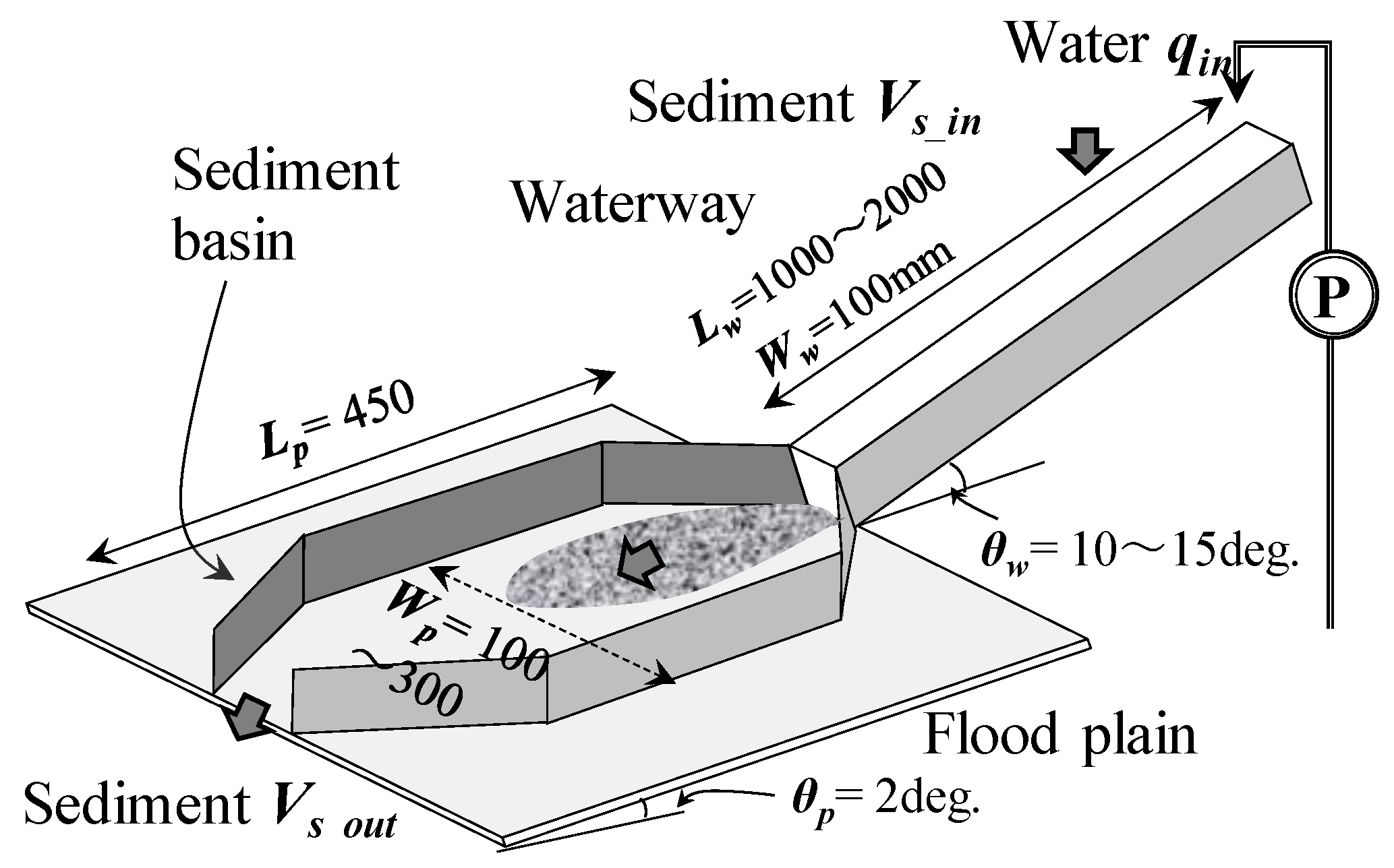
Figure 4 shows the waterway set-up used in the sediment-control experiments for the sediment retarding basin, in which the installation was assumed to be in the proximity of a valley exit. A scale of 1/100 was used for our basin model with reference to the experimental scale of previous studies [6,7]. As shown in the figure, a straight channel (width, Ww = 100 mm) was connected upstream of the planar flooding platform (θp = 2°: maximum and minimum gradient of the debris flow). Water (at a rate of qin) and earth and sand (Vs_in, silica sand [15] was injected independently) were supplied from upstream of the channel (θw = 10° to 15°). The sediment basin had a length (Lp) of 450 mm and a width (Wp) of 100 to 300 mm. We measured the amount of sediment (Vs_out) that passed through the sediment retarding basin and flowed downstream [13]. The amount of sediment supply Vs_in was approximately equal to the maximum amount captured by the sediment retarding basin under each condition of the preliminary experiment. In the experiments, sediment was laid on the bottom of the straight channel in advance. Running water was then allowed to flow through the channel, which gradually eroded away the sediment. The sediment was transported from the upstream channel downstream to the basin as a sediment flow. Here, the water supply was limited to the time at which all of the upper sediment had been eroded away and flowed downstream. The maximum width of the sediment retarding basin (Wp_max = 300 mm) was set as the width required for sedimentation when no side wall was present in the preliminary experiment. The length of the sediment retarding basin (Lp = 450 mm) was set with reference to the current construction guidelines. In the preliminary experiment, Lw = 2000 mm was applied, in consideration of the influence of the change in the channel length Lw.
There is a need to understand the effects of different conditions (e.g., rainfall rate or water supply rate, qin) and basin configurations (e.g., basin width Wp and installation of corners Figure 5 and Ref. [13]) on the effectiveness of the basin to control the sediment and debris flow. Considering the non-uniformity of the experimental results, we conducted three experimental trials under the same conditions and averaged the results. In the preliminary experiment, the average error of the extreme value with respect to the average value of the results of the three experiments was approximately 5%.

2.2. Experimental Results and Discussion

The sediment capture rate fs of our sediment retarding basin is given by
fs = (Vs_inVs_out)/Vs_in.
Hereafter, we describe our experimental results with respect to the basic basin design shown in Figure 4.
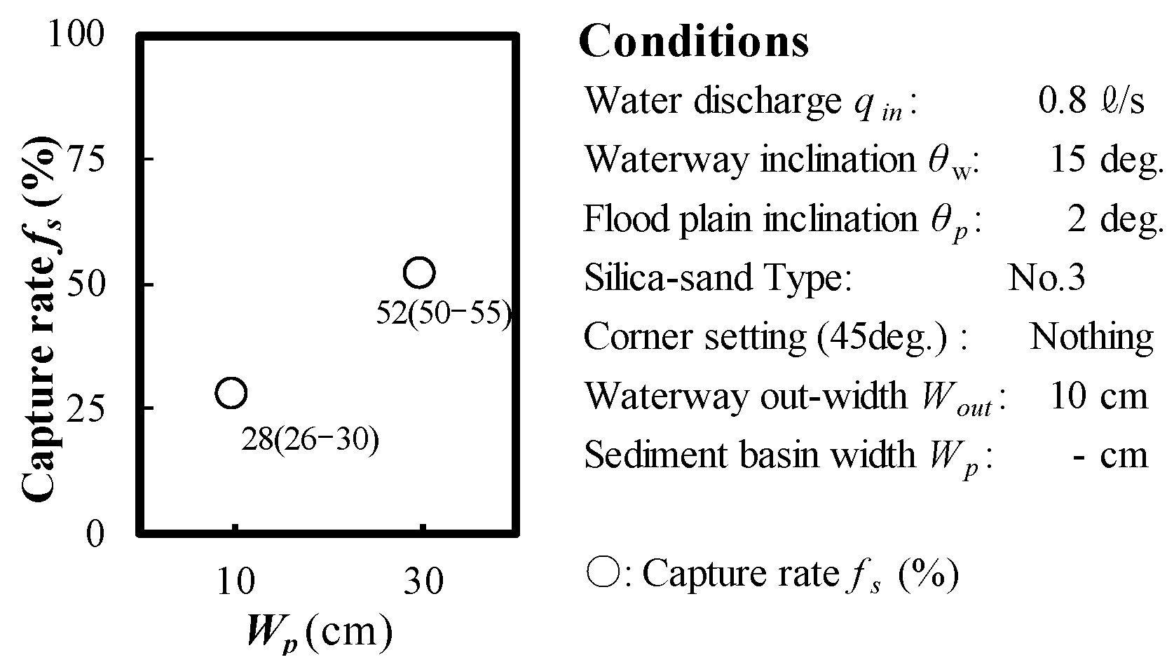
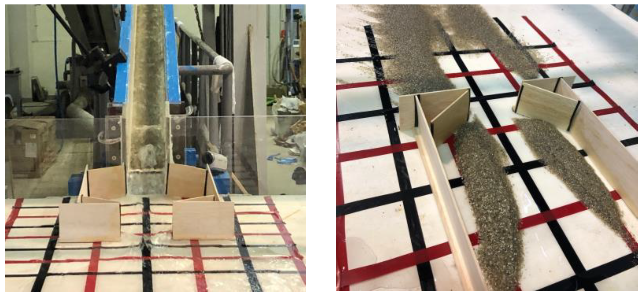
Figure 6 and Figure 7 show the effects of changing the basin width Wp on the capture rate fs of the basin. The numbers in the figure indicate the result range and average value of the three trials. When Wp was 10 cm (i.e., identical to the width of the upstream straight channel Ww), the average value of fs was approximately 28% (minimum value: 26%; maximum value: 30%). When the width was widened to Wp = 30 cm, the fs was approximately 52%; under these conditions (Figure 7), a large amount of sand passed through the sediment retarding basins and flowed downstream. Notably, changing the longitudinal gradient to θw/θp = 15°/2° improved the functionality by 30%, while widening the flow path to Wp/Ww = 30 cm/10 cm provided an improvement of approximately 20% in functionality. According to our observations during the experiment, the sediment was captured at some point by the sediment retarding basin. However, this sediment was then eroded away gradually by subsequent flow to the downstream area; thus, the final capture rate fs was approximately 50%. When the water supply time was further extended, and water was supplied until there were no significant changes, the sediment capture rate fs changed by approximately 10% (e.g., decreased from 52% to 42%). Thus, these results indicate that the shape of the sediment retarding basin is an important factor for sediment capture.
Figure 8 shows the effects of changing the water supply flow rate qin on the sediment capture rate fs, in which fs increased with qin. According to our observations during the experiment, when the flow rate is large, a large amount of sediment transports the sediment in the canal downstream. Additionally, a large amount of sediment is trapped in the sediment retarding basin, which is significantly affected by the change in flow between the canal and sediment retarding basin.
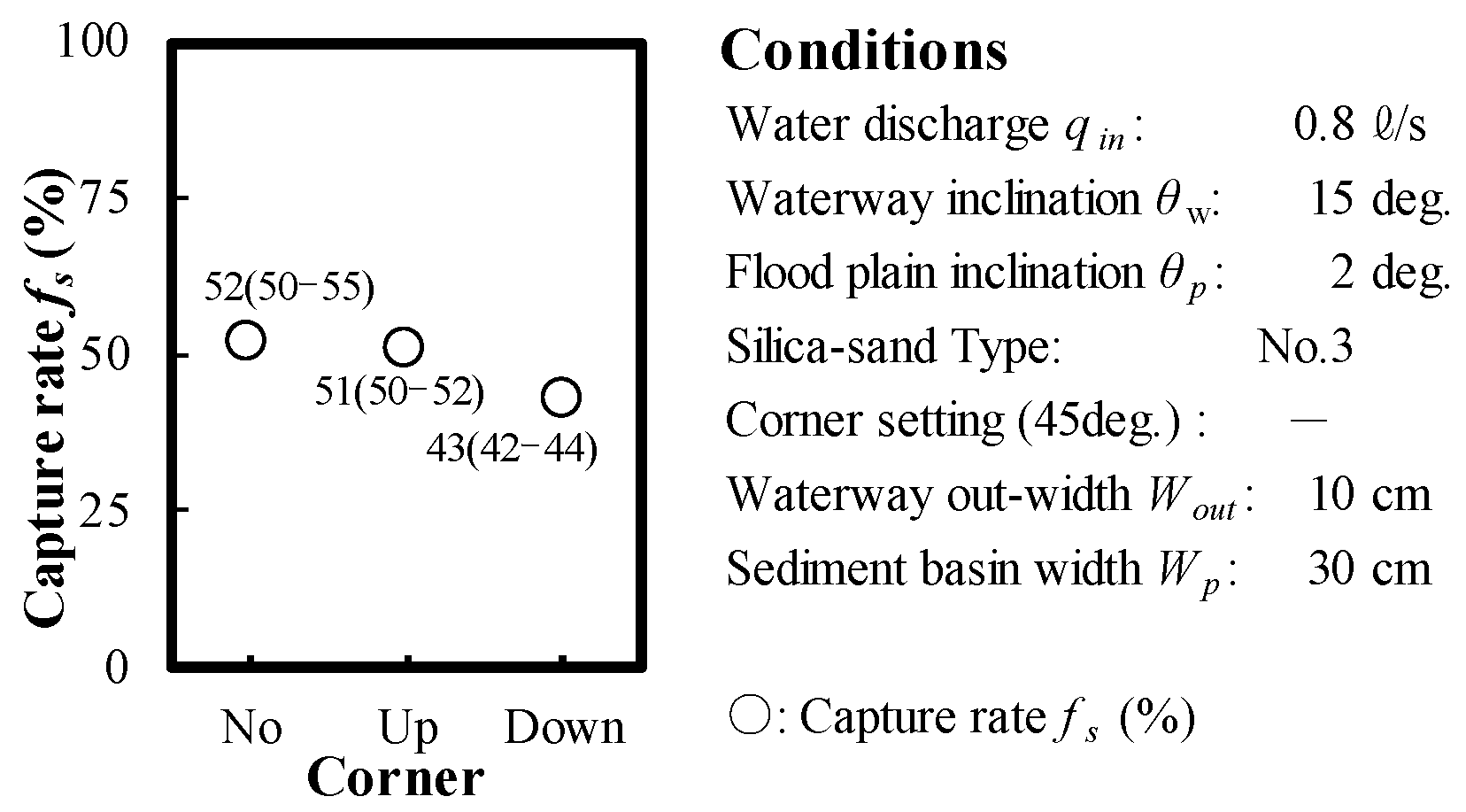
Figure 9 shows the effect of the presence or absence of corners in the basin (referring to Figure 5 that shows 45° corners [13]) on the capture rate fs. There was little to no effect on fs between the absence of corners (Corner: NO) and the presence of upstream corners (Up). Conversely, when corners were installed on the downstream side (Down), fs decreased by approximately 10% with respect to the absence of corners (i.e., NO).
Figure 10 shows the effects of changing the downstream opening width Wout of the sediment retarding basin on the sediment capture rate fs. When Wout was gradually contracted with respect to the inflow width Ww, the capture rate fs significantly improved (Figure 11).
Figure 12 shows diagrams of the changes in the sediment flow with respect to the basin shape. When Wout was wide and corners were installed in the basin (Figure 12, left), a planar flow was generated from the area upstream to the area downstream inside the basin, with outward flow of the sediment from the basin to further downstream. In contrast, when Wout was narrow and no corners were installed (Figure 12, right), sediment capture improved, due to the influence of a planar outward vortex generated in the downstream area inside the sediment basin.
Taken together, these results indicate that the shape of the sediment retarding basin and the backwater effect in the flooded area due to gradual flow contraction at the downstream opening, as well as the width of this opening, affect the sediment control function of sediment retarding basins. In the future, further detailed studies will be needed to resolve the effects of differences in the flow rate, sand supply conditions, longitudinal gradient changes (θw/θp), and other aspects over time on the sediment treatment function. This was a small-scale (1/100) experiment due to the restrictions of the experimental conditions, but a large-scale experiment should be conducted in the future. Furthermore, the average value was obtained from three experiments for each condition, so it will be necessary to increase the number of experiments in future studies.

3. Analysis of Sediment Control Function of Wood Debris Retarding Basins

3.1. Experimental Outline

Figure 13 shows the waterway used in the experiment for the sediment retarding basin. As shown in Figure 4, water (qin) and wood debris (number: Nw_in) were supplied from upstream of the straight channel, and the amount of wood debris (Nw_out) that flowed out of the basin was measured. The wood debris consisted of cylindrical pieces of wood (diameter: 3 mm; length Lw = 5 to 10 cm; specific gravity: 0.75). The wood debris was added manually (the amount of wood debris input per hour was approximately 1 piece every 0.5 s [16]), and the amount of debris captured was measured [14].
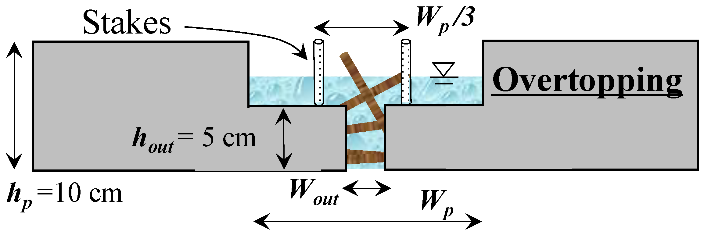
As a potential countermeasure against the outflow of wood debris from the basin due to overflow when the downstream opening width Wout of the basin becomes narrowed, we proposed a countermeasure stake structure, as shown in Figure 14. Figure 15 shows verification of the effectiveness of the capture structure. In the preliminary experiments, in the absence of this countermeasure, a large amount of wood debris flowed downstream due to the overflow caused by the narrow opening.
The effects of each condition on the capture function in the sediment retarding basin and the behavior of the wood debris in the basin were examined with respect to corner installations (Figure 5). These aspects were also examined by changing qin, Wp, the downstream opening width Wout of the basin, and the number of supplied wood debris pieces Nw_in (32 cases) (Figure 13). To address the non-uniformity of the experimental results, we conducted three experimental trials under the same conditions and averaged the results of these trials. In the preliminary experiment, the average error of the extreme value with respect to the average value of the results of the three experiments was approximately 7%.

3.2. Experimental Results and Discussion

From our experimental results on wood debris control, the wood debris capture rate fw of the sediment retarding basin is given by
fw = (Nw_inNw_out)/Nw_in.
Hereafter, we consider experimental results for the basin set-up shown in Figure 13.
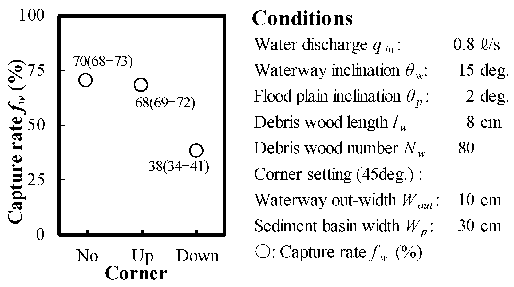
Figure 16 shows the effects of changes in the downstream opening width Wout of sediment retarding basins on the wood debris capture rate fw. When the sediment retarding basin opening width Wout was narrowed, the wood debris capture rate fw significantly improved. Figure 17 shows the effect of the difference in the presence or absence of corners (Figure 5) installed upstream and downstream in the sediment retarding basin on wood debris capture. There was no significant difference in fw between a configuration without corners installed (Corner: NO) and a configuration with upstream corners installed (Up), similar to the sediment findings. However, when corners were installed on the downstream side (Down), the control function was significantly reduced (by approximately 30%) compared with the control function in the absence of corner installations; similar to the sediment capture effect shown in Figure 9.
Figure 18 shows the effect of the difference in the shape of the sediment retarding basin on the flow conditions and the capture function. When Wout was wide and downstream corners were installed (Figure 18, left), a smooth flow downstream occurred in the sediment retarding basin, and most of the wood debris flowed out of the basin to areas downstream. In contrast, when Wout was narrow and no corners were installed (Figure 18, right), the wood debris accumulated as a flat vortex in the transverse direction, which was affected by the narrowing of the downstream opening width. In the presence of a large water level difference due to backwater near the sediment retarding basin opening, the generated planar vortex became more prominent, and a large amount of wood debris was captured. With the addition of stakes installed as a debris flow countermeasure (Figure 14), a large amount of the wood was captured by the basin. There was no outflow of wood debris downstream due to changes in the flow conditions, such as the disappearance of backwater due to suspension of the water supply. Although there is some concern that these capture mechanisms are affected by the specific gravity and shape of the wood debris, these countermeasures are considered generally appropriate, compared with earlier configurations described in the literature [2].
Figure 19 shows the effects of changes in the supply flow rate qin on the wood debris capture rate fw of the sediment retarding basins. The capture rate fw decreased with the supply flow rate qin. From our observations during the experiment, the flat vortex flow became remarkable due to the backwater effect, and most of the wood debris was captured by the sediment retarding basin.
Finally, Figure 20 shows the effects of changes in the amount of supplied wood debris Nw_in on the sediment capture rate fw. Although the change was not remarkable, fw slightly improved as the amount of supplied wood debris increased. According to our observations during the experiment, when the amount of supplied wood was large, the wood debris that flowed down after the initial influx of wood debris was easily captured at the opening by the blockage [16].
These experimental results were applied to devise the shape of the sediment retarding basin. Future studies should further investigate the effects and necessity of downstream corners; we will focus on this and the differences in other conditions using additional experiments and analytical models [17]. In addition, the average value was obtained from three experiments for each condition, so it will be necessary to increase the number of experiments in future studies. As shown in previous studies ([11,18,19]), it is necessary to pay attention to the load-bearing performance of stakes in the actual design. In this experiment, the water depth was shallow, and the three-dimensional effect of the water flow was small. Future studies should examine the effect of the load on structures due to the change in water depth when the flow rate is high [20].

4. Numerical Analysis of the Control Function of Sediment Retarding Basins

Numerical analysis was used to simulate the ability of the sediment retarding basin to control sediment flow; the simulation results were compared with the experimental results described in the previous section. In this study, a one-dimensional analysis model was used for the manual [21].

4.1. Flow Equation

As the basic equation of flow in a fluidized bed, one-dimensional unsteady flow was applied for uniform gravel [4,15]. The equation of motion of the flow, the continuous equation of the total volume, the continuous equation of the sediment in running water, and the continuous equation of the riverbed are expressed as Equation (3), Equation (6), respectively, as follows:
u t   +   u u x   =   g H x     τ b ρ m h   ,
h t   +   u h x   =   i b   ,
C h t   +   u h C x   =   i b C *   ,
z t   +   i b   =   0   ,
where h is the flow depth, u is the cross-sectional average flow velocity, g is the acceleration due to gravity, H is the flow surface elevation, z is the riverbed height, C is the sediment concentration of the fluid layer, t is the time, C* is the sediment concentration of the sedimentary layer, Ρm is the unit volume weight of the liquid phase containing fine particles (fine gravel), τb is the riverbed shear stress, and ib is the erosion rate.
The riverbed shear force considering the motion form [4] is as follows, with respect to the sediment concentration:
When C ≥ 0.4 C* (debris flow):
τ b ρ h   =   1 8 d m 2 h 3 u u G C   ,
G   C   =   C   +   1     C ρ σ C * C 1 / 3     1 2 .
When 0.01 < C < 0.4 C* (bed load collective flow):
τ b ρ h   =   d m 2 h 3 u u 0.49   .
When C < 0.01 or h/d ≥ 30 (quicksand):
τ b ρ h   =   g n m 2 u u h 4 3   .
Here, ρ is the unit volume weight of the sand particles, nm is the Manning roughness coefficient, and dm is the particle size. The erosion and sedimentation of the riverbeds are described as follows:
Erosion (ib ≥ 0):
i b   =   δ e C     C C *     C u h d m   .
Sedimentation (ib < 0):
i b   =   δ d C     C C * u h h   ,
C   =   ρ m t a n θ σ ρ t a n ϕ     t a n θ   .
where δd is the deposition rate coefficient, δe is the erosion rate coefficient, C is the equilibrium sand concentration, θ is the water surface gradient, and φ is the internal friction angle of the gravel. For others, refer to the literature [4].

4.2. Analysis Conditions

For the analysis conditions, we assumed the following: a unit volume weight of sand particles (σ) of 2650 kg/m3, a unit volume weight of the liquid phase containing fine particles (fine grain gravel, ρm) of 1100 kg/m3, an internal friction angle of the sand gravel (φ) of 37°, a sediment concentration (C*) of the sedimentary layer of 0.65, acceleration due to gravity (g) of 9.8 m/s2, an erosion rate coefficient (δe) of 0.0007, a sedimentation rate coefficient (δd) of 0.1, Δt of 0.001 s, Δx of 0.5 m, rough Manning, and a degree coefficient nm of 0.01 m−1/3s. The other conditions were varied to determine the effect.

4.3. Reproduction of the Experimental Results

Using the one-dimensional analysis model constructed for the sediment control function of sediment retarding basins, the experimental results (scale: 1/100) were reproduced and calculated to determine the applicability of the proposed analysis model. Figure 21 shows a comparison between the experimental and simulation results with respect to changes in the sediment retarding basin width Wp (Figure 4) on the sediment capture rate fs with respect to the straight channel width Ww. Figure 21 generally shows good agreement between the model and the results. The analysis results were more susceptible to widening, compared with the experimental results. As one of the factors, the one-dimensional analysis model was presumed to be significantly affected by the change in flow velocity due to the widening.
Figure 22 shows the reproduction results for changes in the most downstream outlet opening width Wout (Figure 5) of the sediment retarding basin. General reproducibility was confirmed (correlation coefficient: 0.98). The reproducibility associated with the change in the downstream opening width was smaller than the experimental results, in contrast to the tendency shown in Figure 18. In this case, the backwater effect and the flow in the transverse direction due to the narrowing of the opening width could not be sufficiently reproduced by the one-dimensional analysis model.
Figure 23 shows the reproduction results for changes in the supply flow rate qin (Figure 4) from the upstream; as shown in Figure 23, general reproducibility was confirmed (correlation coefficient: 0.95).
Figure 24 shows the reproduction results of sediment trapping fs when corners were added to the sediment retarding basin (Figure 5). As shown in Figure 24, the reproducibility decreased, dissimilar to the previous trends (correlation coefficient: 0.59). In particular, the installation of downstream corners (Down) could not be reproduced. In this case, the one-dimensional analysis model was unable to describe the planar flow in the transverse direction in the basin due to the corner installations.
The results thus far indicate that the proposed one-dimensional analysis model was able to reproduce the experimental results regarding the sediment trapping function of the sediment retarding basins. However, local changes in the flow (e.g., the backwater effect and cross-sectional flow) require further consideration. From the experimental results, the control functions for sediment and wood debris tended to be similar. It was found that the conditions that enhance the soil capture effect also contribute to the wood debris capture effect. In addition, we will investigate study measures to describe backwater and downstream corner effects that we were unable to address with the one-dimensional model.

5. Understanding the Impact on Sediment Control Function Using an Analytical Model

The proposed one-dimensional analysis model can be applied to describe the effects of changes in the width Wp, planar shape, and inflow slope (Figure 4: θw/θp) of the sediment retarding basin on sediment control. Regarding the shape of the sediment retarding basin, the length Lp and width Wp of the basin can be changed, such that the installation area Ap (Lp·Wp) of the sediment retarding basin remains constant.
Figure 25 shows the effects of changing the width (Wp/Ww) and vertical gradient (θw/θp) of the sediment retarding basin directly upstream on the sediment capture rate fs. The results showed that widening of the sand area and changing the slope upstream affect sediment capture. This is likely due to changes in the water depth and flow velocity that affect sedimentation.
Figure 26 shows the effects of the downstream opening width (Wout/Wp) of the sediment retarding basin and the gradient change (θw/θp) directly upstream on sediment capture fs. A backwater effect is expected due to narrowing of the downstream opening width of the basin; changes in the water depth and flow velocity are also expected with changes in the gradient. When the gradient change was small and there was no gradual contraction of the basin opening width, most sediment flowed downstream from the basin.
Figure 27 shows the effects of changes in the plane shape (Lp/Wp) of the sediment retarding basin, in which the installation area Ap of the sediment retarding basin is constant, and changes in the supply flow rate qin on sediment capture fs. When the ratio of the sediment retarding basin width to the basin length (Lw/Lp) was 1 or more (long shape in the longitudinal direction), there was little to no change in fs.
Figure 28 shows the effects of the planar shape (Lp/Wp) of the sediment retarding basin and the gradient change (θw/θp) immediately upstream of the sediment retarding basin on sediment capture fs. The change in the gradient showed a different tendency in the relationship between the shape of the sediment retarding basin and the sediment capture.
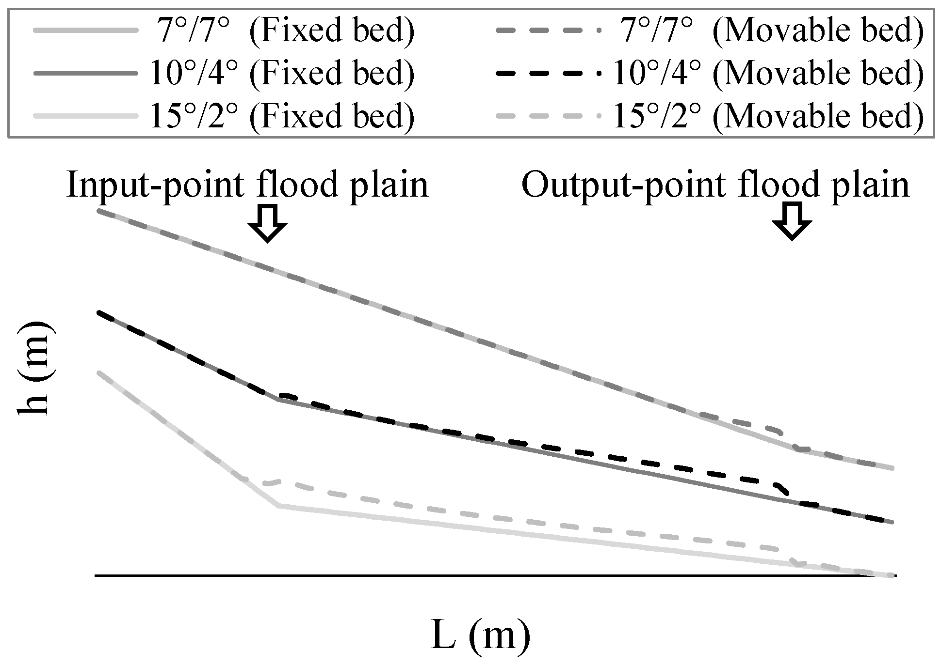
Figure 29 shows the sedimentation shape (longitudinal view) in the final sediment retarding basin for each gradient change (7°/7°, 10°/4°, and 15°/2°). When the gradient change was small (θw/θp = 10°/4°), a large amount of debris was deposited near the downstream opening. In contrast, when the gradient change was large (θw/θp = 15°/2°), the entire debris amount was deposited in the basin. This suggests that a wide river channel (Lp/Wp <<) shape is significant for sediment capture fs in the sediment retarding basin with a small gradient change. The change in Lp/Wp is related to Wp/Ww; thus, the difference in these ratios affects sediment capture. This also explains why the sediment was transported continuously while the flow velocity remained high, because the water depth increased significantly due to narrowing of the basin width due to the side wall, despite the change in the gradient.
Based on the results shown in Figure 27 and Figure 28, we suggest that a sediment retarding basin with a width aspect ratio (Lp/Wp) of approximately 1 (nearly square planar shape) is more effective, compared with existing land constraints. Furthermore, regarding the installation position of the sediment retarding basin, the effectiveness of countermeasures near the gradient change point close to the valley exit should also be considered, as discussed in Section 3.
In the future, further detailed examinations are required, because there are many parameters and conditions to consider for achieving a highly functional sediment retarding basin design. In particular, the one-dimensional model adopted in this study cannot reproduce the effect of the planar eddy current shown in Figure 12 in detail, so we plan to upgrade it with a two- or three-dimensional model in the future.

6. Conclusions

In this study, the detailed structure of sediment retarding basins was examined experimentally and through simulations to optimize the functionality of the basin and its ability to control sediment and wood debris runoff during serious flooding conditions. We constructed a one-dimensional analysis model to describe our basic experimental results and verified its reproducibility. Finally, using our analysis model, we considered the effects of different conditions (for example, changes in the gradient and opening widths of the waterway and basin) on the control aspects of the basin.
According to the results of the channel experiment, the ability of the sediment retarding basin to control flood water and debris depended on the flow conditions, the shape of the basin, and the opening width of the basin at the downstream end. The installation of downstream corners reduced the control function; however, continuing investigation is necessary.
A one-dimensional analysis model was constructed to describe the sediment and wood debris transport observed in our experiments. We confirmed that our model could reproduce our experimental results. However, more detailed structures and basin configurations will likely require a more complex model. Finally, our results indicated that the overall shape of the basin could be optimized to allow for better control over sediment and debris flow. Specifically, an aspect ratio (basin extension/length-to-width ratio) of approximately 1 (square or nearly square) was especially effective in capturing the sediment and wood debris; this would also need to be examined in greater detail to adjust for variations in the runoff gradient and the conditions leading to flooding.

Author Contributions

Conceptualization, N.H., I.K. and T.M.; methodology, N.H. and Y.S.; formal analysis, K.N., Y.S. and I.K.; experiment, N.H. and Y.S.; writing-original draft preparation, N.H.; writing-review and editing, I.K.; funding acquisition, T.M. and I.K. All authors have read and agreed to the published version of the manuscript.

Funding

This work was supported by JSPS KAKENHI grants: Grant-in-Aid for Scientific Research (A) (grant number JP20H00263) and Grant-in-Aid for Scientific Research (B) (grant number JP20H02254). The sponsor had no role in the design, execution, interpretation, or writing of the study.

Institutional Review Board Statement

Not applicable.

Informed Consent Statement

Not applicable.

Data Availability Statement

The data presented in this study are available on request from the corresponding author.

Conflicts of Interest

The authors declare no conflict of interest.

References

  1. Fujita, M. Influence of climate change on sediment disasters. J. Jpn. Soc. Eros. Control Eng. 2012, 65, 14–20. [Google Scholar]
  2. Japanese Ministry of Land, Infrastructure and Transport, SABO. Available online: http://www.mlit.go.jp/mizukokudo/sabo (accessed on 1 November 2021).
  3. Japan Meteorological Agency. Available online: https://www.data.jma.go.jp/obd/stats/etrn (accessed on 1 November 2021).
  4. Takahashi, T.; Nakagawa, H. Prediction of stone debris flow induced by severe rainfall. J. Jpn. Soc. Eros. Control. Eng. 1991, 44, 12–19. [Google Scholar]
  5. Technical Standards for River Works; Japanese Ministry of Land, Infrastructure and Transport: Tokyo, Japan, 2019.
  6. Matsumura, K.; Ishikawa, Y.; Osanii, T. An experimental study on sedimentation process on sediment retarding basins. J. Jpn. Soc. Eros. Control. Eng. 2001, 54, 33–42. [Google Scholar]
  7. Takahashi, T.; Satofuka, Y. Simulation model for channel variation in braided channel reach. Annuals od Disas. Prev. Res. Inst. Kyoto Univ. 1999, 42, 189–200. [Google Scholar]
  8. Hasanpour, A.; Istrati, D.; Buckle, I. Coupled SPH–FEM Modeling of Tsunami-Borne Large Debris Flow and Impact on Coastal Structures. J. Mar. Sci. Eng. 2021, 9, 1068. [Google Scholar] [CrossRef]
  9. Zischg, A.P.; Galatioto, N.; Deplazes, S.; Weingartner, R.; Leonardi, B. Numerical Simulation of Debris Flow and Interaction between Flow and Obstacle via DEM. Ph.D. Thesis, ETH Zürich, Zürich, Switzerland, 2015. [Google Scholar]
  10. Trujillo-Vela, M.G.; Galindo-Torres, S.A.; Zhang, X.; Ramos-Canon, A.M.; Escobar-Vargas, J.A. Smooth particle hydrodynamics and discrete element method coupling scheme for the simulation of debris flows. Comput. Geo Tech. 2020, 125, 103669. [Google Scholar] [CrossRef]
  11. Zhao, T. Investigation of Landslide-induced Debris Flows by the DEM and CFD. Ph.D. Thesis, University of Oxford, Oxford, UK, 2014. [Google Scholar]
  12. Zischg, A.P.; Galatioto, N.; Deplazes, S.; Weingartner, R.; Mazzorana, B. Modelling spatiotemporal dynamics of large wood recruitment, transport, and deposition at the river reach scale during extreme floods. Water 2018, 10, 1134. [Google Scholar] [CrossRef] [Green Version]
  13. SABO. Manual of Technical Standard for Establishing Sabo Master Plan for Debris Flow and Driftwood; Japanese Ministry of Land, Infrastructure and Transport: Tokyo, Japan, 2016. [Google Scholar]
  14. SABO. Japan Implementation of Debris Wood Measures–Immediate Response. In Office Contact; Japanese Ministry of Land, Infrastructure and Transport: Tokyo, Japan, 2015. [Google Scholar]
  15. What Is Silica Stone/Silica Sand (Quartz Stone/Silica Sand). Available online: http://www.mikawakeiseki.co.jp/silica.htm (accessed on 1 November 2021).
  16. Harada, N.; Takayama, S.; Satofuka, Y.; Mizuyama, T.; Nakatani, K. Fundamental experiment using steel stakes to capture driftwood on an impermeable type sabo dam. Annu. J. Hydraul. Eng. JSCE 2017, 73, 1351–1356. [Google Scholar] [CrossRef] [Green Version]
  17. Kimura, I.; Kitazono, K. Effects of the driftwood Richardson number and applicability of a 3D–2D model to heavy wood jamming around obstacles. Environ. Fluid Mech. 2020, 20, 503–525. [Google Scholar] [CrossRef]
  18. Shafiei, S.; Melville, B.; Shamseldin, A.; Beskhyroun, S.; Adams, K. Experimental investigation of tsunami- borne debris impact force on structures: Factors affecting impulse-momentum formula. Ocean. Eng. 2016, 127, 158–169. [Google Scholar] [CrossRef]
  19. Haehnel, R.; Daly, S. Maximum impact force of woody debris on floodplain structures. J. Hydraul. Eng. 2004, 130, 112–120. [Google Scholar] [CrossRef]
  20. Istrati, D.; Hasanpour, A.; Buckle, I. Numerical Investigation of Tsunami-Borne Debris Damming Loads on a Coastal Bridge. In Proceedings of the 17 World Conference on Earthquake Engineering, Sendai, Japan, 27 September–2 October 2021; Available online: https://www.researchgate.net/publication/342027873_Numerical_Investigation_of_Tsunami-Borne_Debris_Damming_Loads_on_a_Coastal_Bridge5542020 (accessed on 1 November 2021).
  21. Satofuka, Y.; Mizuayma, T. Numerical simulation on a debris flow in a mountainous river with a Sabo dam. J. Jpn. Soc. Eros. Control. Eng. 2005, 58, 21–27. [Google Scholar]
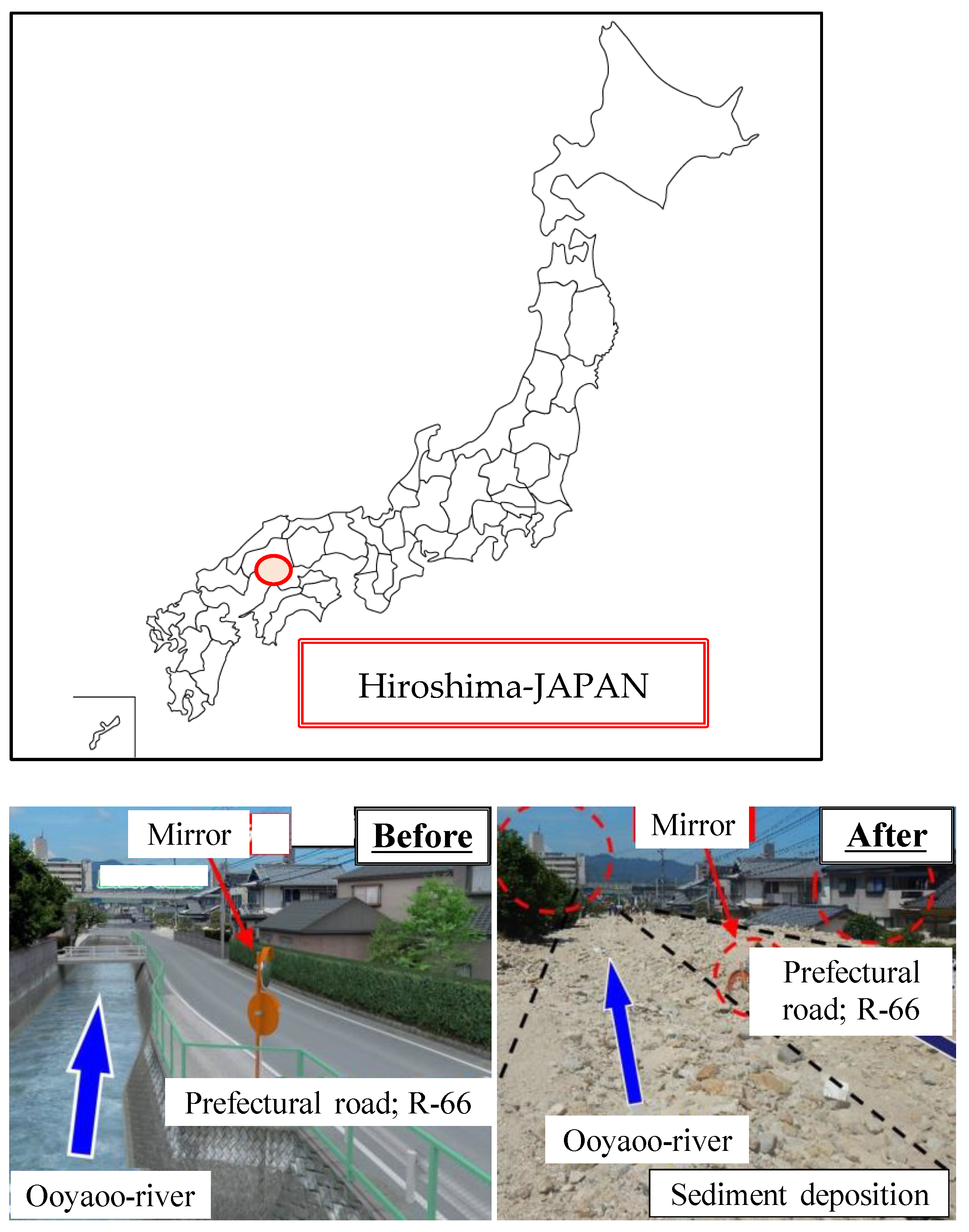
Figure 1. Damage caused by sediment and wood debris (H30, Hiroshima: Oya Okawa). Left: before the disaster; right: after the disaster [2].
Water 13 03283 g001
Figure 2. Damage caused by heavy rain in Hiroshima (left: H26, right: H30) [2].
Water 13 03283 g002
Figure 3. Heavy Rainfall in Hiroshima (H26, H30) [3].
Water 13 03283 g003
Figure 4. Outline of the experimental set-up.
Water 13 03283 g004
Figure 5. Sediment retarding basin plan view (left: with corners, right: without corners).
Water 13 03283 g005
Figure 6. Effects of changing the basin width Wp on the capture rate fs of the sediment retarding basin.
Water 13 03283 g006
Figure 7. Experimental status (left: experimental equipment, right: sediment control status).
Water 13 03283 g007
Figure 8. Effects of changes in the supply flow qin rate on the sediment catch rate in the sediment retarding basins.
Water 13 03283 g008
Figure 9. Effect of the presence or absence of corners in the sediment retarding basins on the capture rate fs.
Water 13 03283 g009
Figure 10. Effects of changes in the downstream opening width Wout of the sediment retarding basins on the sediment capture rate fs.
Water 13 03283 g010
Figure 11. Control (capture) status by the weiring effect.
Water 13 03283 g011
Figure 12. Effect of shape changes in the sediment basin on the flow conditions and containment (left: with corners; right: without corners).
Water 13 03283 g012
Figure 13. Outline of the experiment.
Water 13 03283 g013
Figure 14. Wood debris trapping installation in the downstream opening of the sediment retarding basin as a countermeasure.
Water 13 03283 g014
Figure 15. Wood debris control/capture status.
Water 13 03283 g015
Figure 16. Effects of the change in the downstream opening width of the sediment retarding basin on the wood debris capture rate.
Water 13 03283 g016
Figure 17. Effects of the difference in the presence or absence of corners on the wood debris capture rate.
Water 13 03283 g017
Figure 18. Effect of different basin shape/configuration (corner installation) on the flow conditions and capture function of the basin. (Left: with corners; right: without corners).
Water 13 03283 g018
Figure 19. Effects of differences in the supply flow rate on the capture rate.
Water 13 03283 g019
Figure 20. Effect of the difference in the amount of supplied wood debris on the capture rate.
Water 13 03283 g020
Figure 21. Comparison of the experimental results and the numerical analysis results for changes in the width of the sediment retarding basin.
Water 13 03283 g021
Figure 22. Comparison of the experimental results and numerical analysis results for changes in the downstream opening width of the sediment retarding basin.
Water 13 03283 g022
Figure 23. Comparison of the experimental results and numerical analysis results for changes in the supply flow rate.
Water 13 03283 g023
Figure 24. Comparison of the experimental results and numerical analysis results for differences in corner installations.
Water 13 03283 g024
Figure 25. Effects of changes in the sediment retarding basin width and gradient on sediment capture.
Water 13 03283 g025
Figure 26. Effects of changes in the downstream opening width and gradient of the sediment retarding basin on sediment capture.
Water 13 03283 g026
Figure 27. Effects of changes in the planar shape of the sediment retarding basin and the supply flow rate on sediment capture.
Water 13 03283 g027
Figure 28. Effects of changes in the planar shape and gradient of the sediment retarding basin on sediment capture.
Water 13 03283 g028
Figure 29. Effect of different gradient changes on sediment shape (longitudinal view).
Water 13 03283 g029
Publisher’s Note: MDPI stays neutral with regard to jurisdictional claims in published maps and institutional affiliations.