Article

Improvement of the Electrical Regulation of a Microhydropower System using a Water Management Tool

by
Melvin Alfonso García Espinal
,
Pilar Conejos
,
Petra Amparo López-Jiménez
and
Modesto Pérez-Sánchez
*
Hydraulic and Environmental Engineering Department, Universitat Politècnica de València, 46022 Valencia, Spain
*
Author to whom correspondence should be addressed.
Water 2022, 14(10), 1535; https://doi.org/10.3390/w14101535
Submission received: 12 April 2022 / Revised: 7 May 2022 / Accepted: 9 May 2022 / Published: 11 May 2022
(This article belongs to the Section Hydraulics and Hydrodynamics)

Abstract

:
The constant growth of the population and the increase in the need for resources create challenges, and it is necessary to seek more sustainable solutions to manage them more adequately and efficiently. In recent years, the use of renewable energy systems has increased, in which water distribution networks are no exception. Pumps operating as turbines (PATs) are an innovative solution with enormous potential to achieve these sustainable development goals. As a means of improving sustainability, in this research, an optimized regulation tool is developed to maximize the recovered energy in the system using PATs in water distribution networks (WDNs). This is possible due to the use of empirical methods for the estimation of the characteristic curves. The tool was developed in Simulink MATLAB, in which the optimization and iterative steps were carried out. It is based on the intended methodology and applied to a real case study. When implementing the tool, the results given are the hydraulic–electrical regulation strategies, where the number of machines working, the frequency inverter setpoint, and the degree of opening of the pressure-reducing valves (PRV) is defined for any given time. After the analysis in the case study, the tool recovered 28% of the supplied energy in the system. This daily recovered energy was above 7160 kWh, and it contributed to an increase in efficiency and sustainability.

1. Introduction

In the search for the sustainable development of society, various authors have carried out studies in which the use of energy recovery systems is proposed, with the so-called microgeneration systems being more commonly used [1]. Population growth has been responsible for an increase in energy and water consumption since the industrial revolution [2]. This caused an increase in the energy cost in different hydraulic systems and the inclusion of management to make the water cycle more sustainable [3]. Renewable energy sources with little or no environmental impacts have led to a global proliferation of this hydropower technology [4], particularly those of the run-of-river type [5]. To improve these sustainable indexes, several studies have shown that the use of microgeneration causes a decrease in pressure and an increase in renewable energy [6] and its optimization in generation [7]. Additionally, this pressure decrease guarantees the improvement of the leakage indexes of the supply network [8].
With the development of strategies focused on ensuring energy and hydraulic efficiencies, such as pressure control for leak reduction or energy recovery using microturbines, it is possible to increase sustainability [9]. In this way, the use of a pump in reverse mode, called a pump working as a turbine (PAT), is a real application that has been considered in recent years [10]. The use of microhydropower systems, joined with other renewable systems such as photovoltaic systems, enables an improvement in the use of clean energies in water distribution systems [11].
The major availability of pumps compared to available turbines improves the feasibility of these facilities, reducing investment and showing low payback, although PAT efficiency is lower than turbine efficiencies [12].
PATs analyses have been developed since the 1940s. Stepanoff [13] was the first to establish a method to estimate the efficiency of the machine when it operates as a turbine, and Childs [14] developed a comparative study of efficiencies when the machines operate as pumps or turbines. Grover [15] proposed linear equations to estimate the best efficiency point of a machine operating as a turbine. Sharma [16] developed a prediction method that uses relationships. These values depend on the efficiency of the pump. Alatorre-Frenk et al. [17] proposed a method based on equations setting a limited number of PATs data, which improved the previous results, and Williams [18] presented a study on the comparison of different calculation methods for turbine performance prediction using the best efficiency value. Fernández et al. [19] observed the influence of the rotational speed on efficiency and obtained the characteristics at constant head and runaway speed. Derakhshan and Nourbakhsh [20] tried to estimate hydraulic parameters (i.e., head, flow, and efficiency) in turbine mode using pump data with CFD techniques. Páscoa et al. [21] proposed a new approach for the PAT power plant, designed based on a constant head, instead of a traditional operation, at a constant flow rate. Rossi and Renzi [22] evaluated both the best efficiency points (BEP) and the performance of PATs in an accurate way using artificial neural networks. Pérez-Sánchez et al. [23] defined new approach equations to estimate the BEP of a PAT and the characteristic curves using an experimental database of 181 different PATs.
Estimating the characteristic curves and the best efficiency point in a PAT requires overcoming new challenges to improve the use of these systems in the future [24]. Systems of the future should be focused on taking advantage of the different regulation strategies and applying affinity laws [25]. The use of these methods enables the hydraulic and electrical regulation of these recovery systems. Additionally, their implementation improves the optimization procedure and includes an increase in the generated energy [26].
This regulation improvement should be supported by optimization tools, with water managers knowing the main constraints of the system (flow over time, upstream pressure, and downstream pressure) to guarantee the quality of service to the end-user [27]. There are only a few previous works that have developed a tool to select PATs or turbines [28]. The tools were focused on defining the best efficiency point, but this analysis was not centered on the interface used to analyze alternatives and develop energy studies [29], improving their operation [30]. A MATLAB Simulink model was developed for simulating a branch of the WDN located in Laives (South-Tyrol) [31] or for analyzing two different scenarios [32]. Simulink was also used to estimate leakages [33], floods control [34], or waste-water treatment modeling [35], among others.
This research develops an interface using a dynamic model by Simulink MATLAB [36]. The optimization tool is focused on the selection of the pump, defining the best regulation strategies (the number of operating machines, rotational speed value, and opening degree valves) at any given time to guarantee the hydraulic constraints of the system and maximize the generated power, which could be supplied to the grid or self-consumed. The main goal of the manuscript is to develop an optimization tool that enables an improvement in PAT management in water systems. The novelty of our work is the focus on the integration of empirical methods, which can estimate the characteristic curves to optimize the operation and select machines based on flow over time as well as the frequency of these flows. The implementation tool is new and crucial to improving sustainability in water distribution systems.

2. Methods

This section proposes a methodology that enables the development of a tool for the analysis of the regulation of an energy-recovery system. As a starting point, there are flow input records and pressure setpoints established at a point in the distribution system, which establish the operating restrictions.
As the object of the application is water supply, this means that there is a variable operation system, and we seek to design a strategy in which energy recovery does not compromise the level of service of the network but can provide an improved solution to the study system.
As shown in Figure 1, the hydraulic model considers there will be a replacement between a pressure-reduction valve (PRV) and a recovery system. The energy recovery equipment has two main groups of elements: PATs and PRVs. A parallel group of three PATs is considered, including two pressure-reducing valves (one in parallel to the machines and another at the outlet, connected in series). The function of these PRVs is the dissipation of the excess of the hydraulic head, which is not recovered by PAT since the downstream pressure is an established constraint, and it must guarantee the correct operation of the water system.
A structured methodology was developed and executed in MATLAB Simulink. MATLAB is desktop software with a programming language that expresses the mathematics of matrices and arrays (vectors or arrays) directly. Simulink is one of the most important MATLAB complements; it allows users to combine textual and graphical programming to design systems in a simulation environment [37]. The tool searches the definition of the signal parameters to define the number of machines operating, their rotational speed, and the opening degree of the PRVs by reading the flow over time and the upstream pressure when the main constraint (the downstream pressure) is known.

Methodology

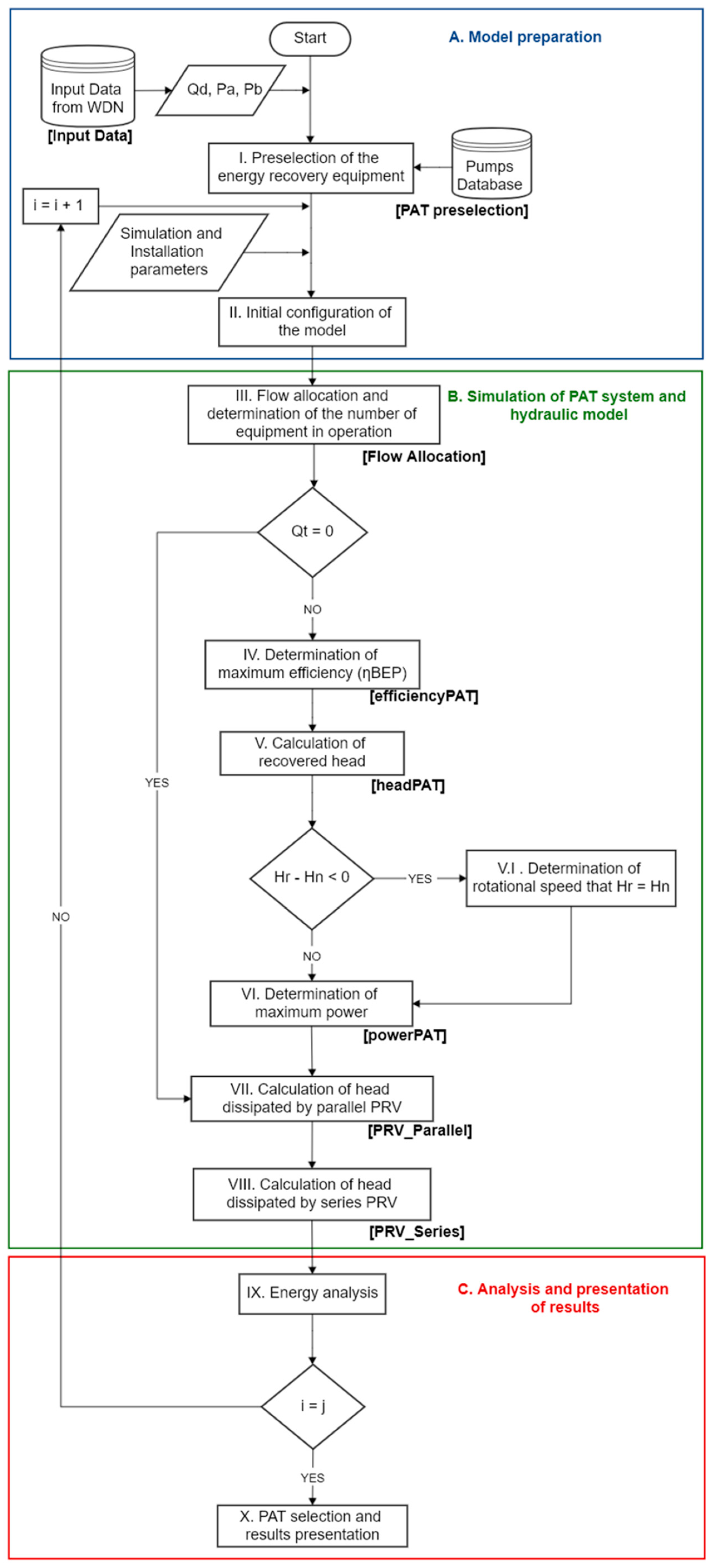
Figure 2 shows the proposed methodology, which is composed of three main blocks: A. Model preparation, B. Simulation of PAT system and hydraulic model, and C. Analysis and presentation of results. Each block is divided into different sections that contain the steps of the different developed actions.
The first block (A. Model Preparation) is focused on the establishment of the input parameters to develop the optimization operation of the recovery systems. Step I is focused on the preselection of the pump working as a turbine. For development, the programmed tool used two different databases. Firstly, the flow and upstream pressure, as well as the downstream pressure (restriction to guarantee the service operation of the system), should be known over time. The selection was developed using the methodology proposed by Camilo Rosado et al. [38]. This methodology contains the following steps: (a) statistical analysis of the data record (flow and upstream and downstream pressures) to define the flow and head more representative of the series. This point will establish the future of both flow and head at the best efficiency point of the machine (QBEPt and HBEPt); (b) calculation of specific numbers in turbine mode (nst) and estimation of coefficients βQ and βH; (c) estimation of the best efficiency point (QBEPp, HBEPp) operating as a pump; (d) selection of the pumps in manufacturer catalog; (e) calculation of specific number in pump mode (nsp); (f) estimation of the characteristics of the equipment working in turbine mode, obtaining QBEPt, HBEPt, and ηBEPt; and lastly, (g) validation if the preselected PAT meets the criteria of (C ≤ 1).
Step II develops the initial configuration of the tool to be implemented in the MATLAB algorithm. It defines the database established in step I and establishes the simulation time steps. The following setup parameters are defined:
  • Parameters of the installed PATs: number of units installed, np (between 1 to 3); nominal rotational speed, no (in rpm); minimum and maximum operating flows of the equipment, Qmint and Qmaxt (in L/s), as well as the BEP (QBEPt, HBEPt, and ηBEPt).
  • The frequency inverter: where the minimum and maximum values of α are defined at which the equipment can work (αmin and αmax).
  • The efficiency of the electric generator: the efficiency of the electric generator is defined with a constant or variable value depending on the mechanical power of the output.
  • Limits for range determine maximum power: the values that will define the search space (lower bound, lb and upper bound, ub) are defined.
  • Pressure Reducing Valves (PRVs): Enter the diameter, Diam (in mm), the valve curve, and the flow coefficient with the valve fully open, Kvo (in m3/h/√Pa).
  • Relative fluid properties: where the density of the fluid is entered according to the operating temperature (in kg/m3) and the acceleration of gravity (in m/s2).
The second block (B. Simulation and hydraulic model), which contains the simulation of the PAT system and hydraulic model, is developed between steps III and VII. It considers the optimization block to optimize the operation of the recovery system, maximizing the generated power by compliance with the constraints (flow and downstream pressure). Five sections comprise this block: B.1 flow allocation and number of equipment in operation (step III); B.2 determination of the maximum efficiency for the installed PAT (step IV); B.3 calculation of the recovered head (step V); B.4 determination of maximum power (step VI); B.5 calculation of head dissipated by the parallel PRV and the output PRV (steps VII and VIII).
Step III establishes the operation conditions of the recovery systems considering the constraints defined by Block A and determines the operating conditions under which the simulation will be carried out at that moment. Defined the number of installed PATs (np), this step establishes the flow range of the operation of PAT. The methodology considered its strategy to estimate the operating flow (Qt) for each PAT and the number of machines operating at each time (nf). The strategies proposed by [39] and the ratio between the maximum and minimum flows of the equipment to be evaluated were taken as a reference, obtaining two possible cases.
Q rt = Q t Q BEP t
where Q rt is the ratio between Qt and QBEPt.
The Q rt value is obtained using Equation (1). It will define the flow strategy to be used with the equipment to be evaluated: 1. For a Q rt value < 0.50, the machine is not operating, and the flow is bypassed for VRP. When Q rt > 2, the flow excess is also bypassed by the VRP. When Q rt is between 0.5 and 2, the system establishes the regulation strategy using the hydraulic machines. At the exit of this step, there is decision-making in which it is verified that flow is not null ( Q t > 0). If this condition is met, the order of the steps is continued, with the next step being the determination of the maximum efficiency.
Otherwise, the next step is the calculations of the heads dissipated by the PRV, meaning that the demanded flow is below the minimum operating flow of the PAT. When the flow of each PAT is known, the procedure estimates the maximum possible efficiency that each machine could reach. It is always sought to be able to work at the point of maximum efficiency (BEP). This point is estimated using dimensionless curves, which were published by Plua et al. [40], as illustrated in the following expressions:
h = - 0 . 31070   α Q t Q BEPt + 0 . 1958 Qt Q BEPt 2 -   0 . 0118 Qt Q BEPt   -   0 . 06429 α 2 + 1 . 8489 α   -   0 . 2241
e = 0 . 8271 α Q t Q BEPt   -   0 . 3187 Qt Q BEPt 2 -   0 . 1758 Qt Q BEPt   -   1 . 035 α 2 + 1 . 1815 α   -   0 . 5019
Ref. [35] found a root mean square error (RMSE) lower than 0.2, and these equations reduced the error values by between 30 and 50% compared with other published methods. The use of these equations enables the estimation of the characteristic curves of the hydraulic machines considering the variable rotational speed.
Reorganizing Equation (3), it is possible to determine the efficiency that the PAT would have at each moment, using the following expression:
η t = η BEPt 0 . 8271 α Q t Q BEPt     0 . 3187 Qt Q BEPt 2     0 . 1758 Qt Q BEPt     1 . 035 α 2 + 1 . 1815 α     0 . 5019
where h is the dimensionless ratio between recovered head and recovered head at the point of maximum efficiency of the PAT; e is the dimensionless ratio between efficiency and efficiency at the point of maximum efficiency of the PAT; Hrt is the head recovered by the PAT (in m w.c.); HBEPt is the head recovered at the point of maximum efficiency (in m w.c.); Qt is the flow rate turbinated by the machine (in L/s); QBEPt is the flow at the point of maximum efficiency (in L/s); ηt is the efficiency of the PAT (in %); ηBEPt is the efficiency of the machine at its optimum point (in %); and α is the rotational speed modifier set by the frequency inverter.
The latter is defined by the ratio between n and no, in which no is the nominal rotational speed of the machine in rpm and n is the rotational speed of the machine in rpm.
Step IV develops an iterative process, exploring the minimum speed of rotation allowed up to the maximum. The turning speed enables the selection of the best process based on which reaches the highest efficiency. Step V estimates the recovered head and compares it with the net available head (Hn), which is the difference between the pressures upstream and downstream of the evaluated point.
This pressure difference is a restriction of the model since it must guarantee the service quality of the users. Rearranging Equation (2), the expression to determine the head recovered at each moment is:
H rt = H BEPt - 0 . 31070   α Q t Q BEPt + 0 . 1958 Qt Q BEPt 2   -   0 . 0118 Qt Q BEPt   -   0 . 06429 α 2 + 1 . 8489 α   -   0 . 2241
H n = P u   -   P d
where Hn is the net head available in m w.c.; Pu is the upstream pressure at the point (in m w.c.), and Pd is the downstream pressure in m w.c.
At the end of step V, it must be checked that the difference between Hn and Hrt is equal to or greater than 0. If this condition is met, step VI is achieved, in which the generated power is optimized, determining a new α value. It should be determined within the established limits in step V. In step VI, a search range defined by the lower and upper limits (lb, ub) is established, where the rotation speed obtained in the recovered head block will be varied until the maximum power is obtained.
The optimization of the power tool enables the estimation of the mechanical power in the axis (MP), the electrically generated power (EP), and the torque (T) in the axis by the following expressions:
MP = γ   · Q t   · H rt ·   η t
EP = MP   ·   η elec
T = 30   ·   MP n   π  
where MP is the mechanical power of the machine in kW; γ is the specific weight of the fluid in kN/m3; g is the acceleration of gravity in m/s2; Qt is the flow rate turbinated by the machine in m3/s; Hrt is the head recovered by the machine (in m w.c.); ηt is the efficiency of the PAT; EP is the electrical power generated by the generator in kW, and ηelec is the efficiency of the generator [36], which depends on rotational speed and power; T is the torque produced by the machine in Nm; and n is the rotational speed of the machine affected in rpm.
Once the instantaneous head recovered by the machine is known, the energy dissipated by the installed PRVs is calculated, in which one is in parallel with the PAT system, and the other is connected cited in series, at the outlet of the supply, as represented in Figure 1.
Steps VII and VIII define the opening degree of both valves that guarantees the downstream pressure restriction.
Finally, section C is focused on the analysis of results. Step IX develops an energy analysis of the installation with the proposed equipment, and step X defines the selection of final equipment, presentation of proposals, and report of results. These ten steps define the main structure of the optimization machine tool.
At the end of this step, decision-making is presented, in which the subscript i of the preselected machine that is being evaluated is verified, and it is compared with the value j of the number of models obtained in the preselection. If they are different, the results of the energy analysis are stored in memory; the value of i is increased, with i = i + 1, and returns to step II, performing a new simulation with the next machine on the list. This means that j different models must be evaluated, and the results obtained from each of these must be stored in memory to be able to compare and select the machine.

3. Results

3.1. Case Study Description

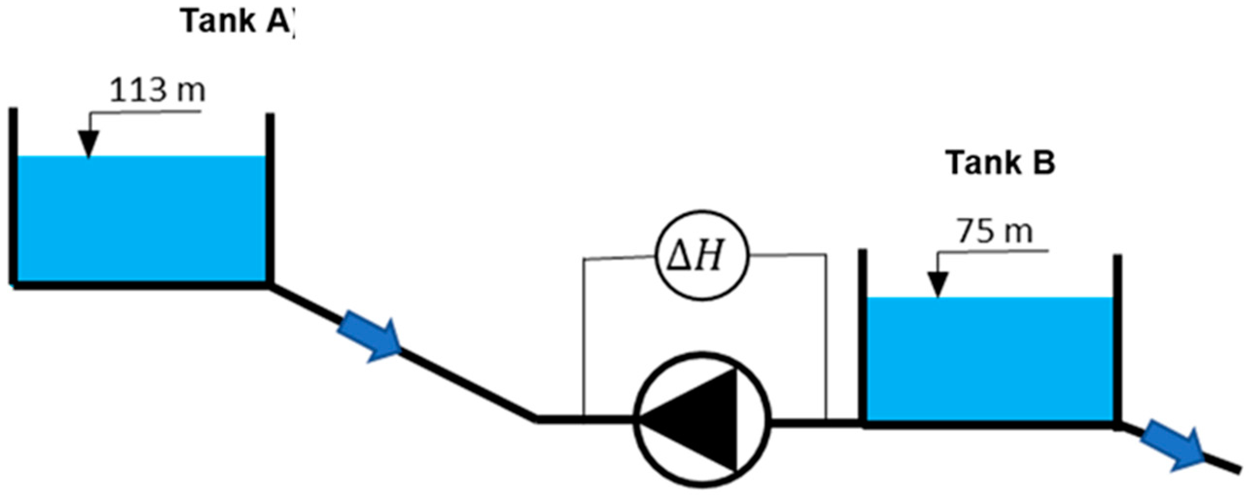
The particular case study to which this methodology was applied is located in Valencia (Spain). It is a supply system that distributes the supplied volume to different municipalities using pressurized water systems. The possibility of installing energy-recovery systems is proposed in the place of making an intermediate deposit to improve the sustainability and efficiency indicators of the distribution system. The main reservoir, called Tank A, is connected to the water network by a pipe. In this line, there is a reservoir, called Tank B, that will enable the installation of the recovery system to take advantage of the potential energy, installing the recovery system and supplying this generated energy in a pump system, which is near tank B.
Figure 3 shows a schematic of the system between Tank A and Tank B. Their water levels are 113 and 75 m, respectively. Both tanks would be connected by a steel pipe. The length of this pipe is 1300 m, and the diameter is 1.4 m.
Table 1 shows the demanded flow (Qd), upstream pressure (Pu), and downstream pressure (Pd) over time. The analysis only considered one day because the system connected two deposits, and the flow is established between them.

3.2. PAT Selection for the Case Study

Following the methodology proposed by Camilo Rosado et al. [36], for the selection of the most suitable PAT for the installation, the following steps must be carried out: (a) Statistical analysis of data record to determine QBEPt and HBEPt; (b) calculation of specific numbers in turbine mode, nst and estimation of coefficients βQ and βH [37]; (c) calculation of QBEPp and HBEPp using the coefficients from the previous step; (d) preselection of equipment that meets the previously calculated Q–H operating point, along with obtaining its optimal operating data; € calculation of specific number in pump mode, nsp, and coefficients βQ, βH, and βη; (f) estimation of the characteristics of the equipment working in turbine mode, obtaining QBEPt, HBEPt, and ηBEPt; (g) calculation of C to verify that the preselected machines meet the established criteria of (C ≤ 1) [18]. An additional step is also included: (h) calculation of recovered energy for each preselected machine and final PAT selection.
Once the steps before the preselection are completed, the characteristics of the preselected machines are obtained, and the calculation of the flow and head error is carried out using Equation (10). The criteria used for acceptance or rejection of the selection were based on ellipse error. This ellipse, which was defined by [18], enables an error of +/−30% and +/−10% in the major and minor axis (flow and head, respectively) of the ellipse compared to the ideal selection point. It enables the determination of the C value, discarding the preselected machines that do not match the criterium of C ≤ 1.
C 2 = 1 2 q + h     0.3 2 + 1 2 q 2 + h 2 2 q h 0.1 2
where C is the error coefficient of the estimated values; ∆q is the error of the estimated flow concerning the selection flow; ∆h is the error of the estimated head for the selection head.
The results obtained from the preselected machines are presented in Table 2. Machine 3 was discarded for not meeting the error criterion, while machine 1 had an error very close to that of the maximum allowable (Table 2). The different expressions used were validated in other published research, which analyzed the different errors and validated them with another case study [37,38]. The optimization tool used these expressions and methodology to choose and operate the recovery systems.
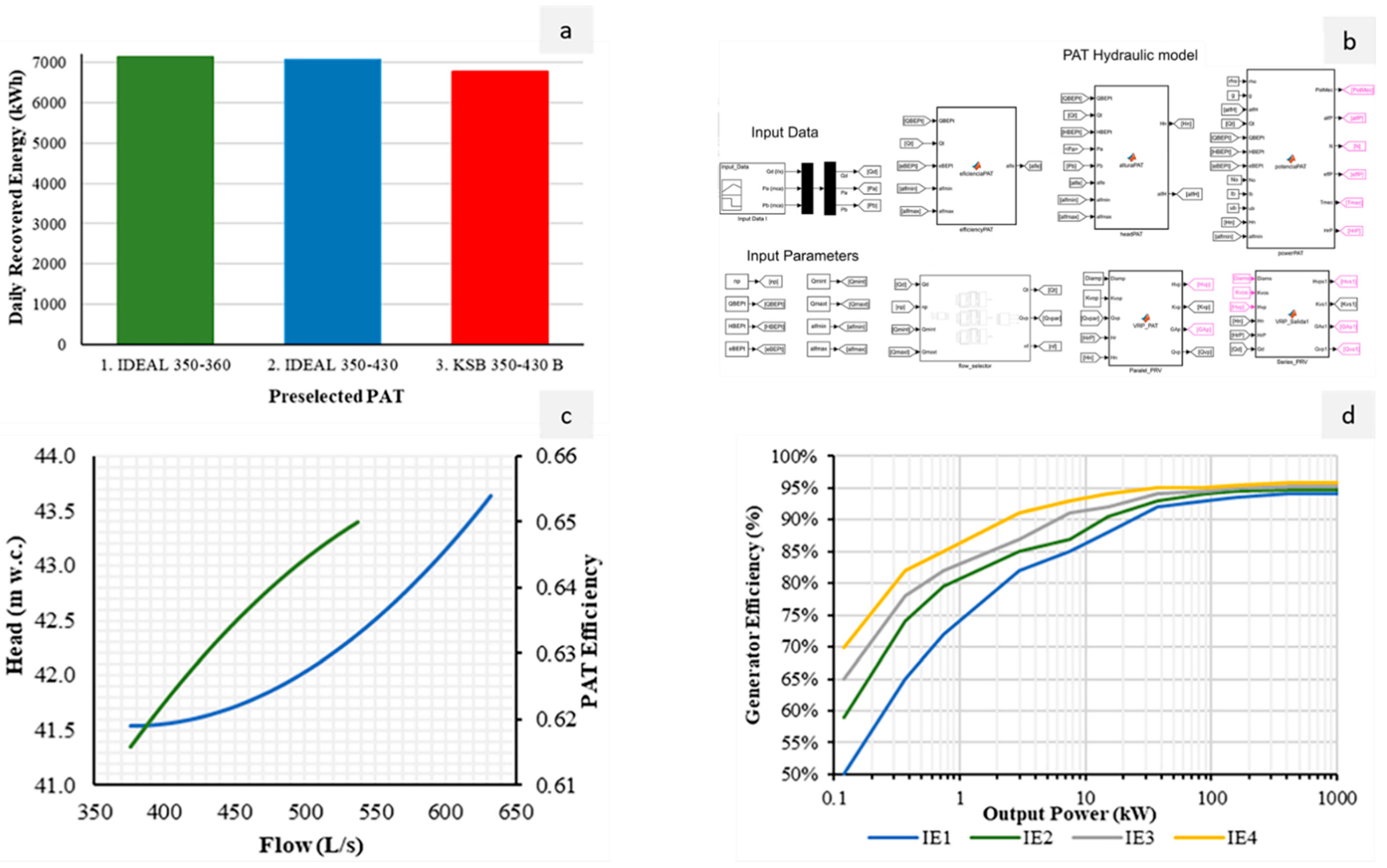
Figure 4a shows the results of the simulation with each machine, and the chosen PAT is highlighted once the different blocks described in the methodology section were programmed and integrated into the optimization tool (Figure 4b).
The selected machine was CPH 350–360 at 50 Hz from the manufacturer Bombas IDEAL, which considered the criterion of maximum daily recovered energy. Once the PAT group was selected, the characteristic was plotted for the nominal rotational according to the expressions defined in the methodology section (Figure 4c). The curves were constructed between the minimum and maximum flow ranges of the PAT.
The minimum operating flow was defined as the flow that resulted in the lowest head recovered at nominal speed, and for this specific case, the maximum flow was obtained by dividing the maximum inlet flow by the number of equipment installed. The recovered head oscillated between 41.53 and 43.64 m w.c. and the efficiency of the hydraulic machine was between 0.62 and 0.66.
To complete the optimization model (Figure 4b), the pressure-reducing valves to be installed in each case must be selected. A valve, whose size was DN150, was installed in parallel, and a valve, whose size was DN350, was installed in serial of the system. The model was Hydrobloc KXG-BELGICAS, and the flow coefficient was 388 and 1389 (m3/h, 1 bar), respectively.
To estimate the energy recovered by the recovery system, the efficiency of the electric motor was considered in the optimization tool. This consideration can be incorporated as a fixed value by [40], or the optimization model enables the definition of this efficiency as a function of the rotational speed and resistive load of the system for isolated grid systems [41]. This energy analysis considered a conservative value, defining the class of generator as IE1 (Figure 4d). When the model considered a conservative value (IE1, Figure 4d), the daily recovered head was 6911 kWh.
Otherwise, if the generator efficiency is considered variable as a function of the rotational speed, the daily recovered energy increased by around 4%.
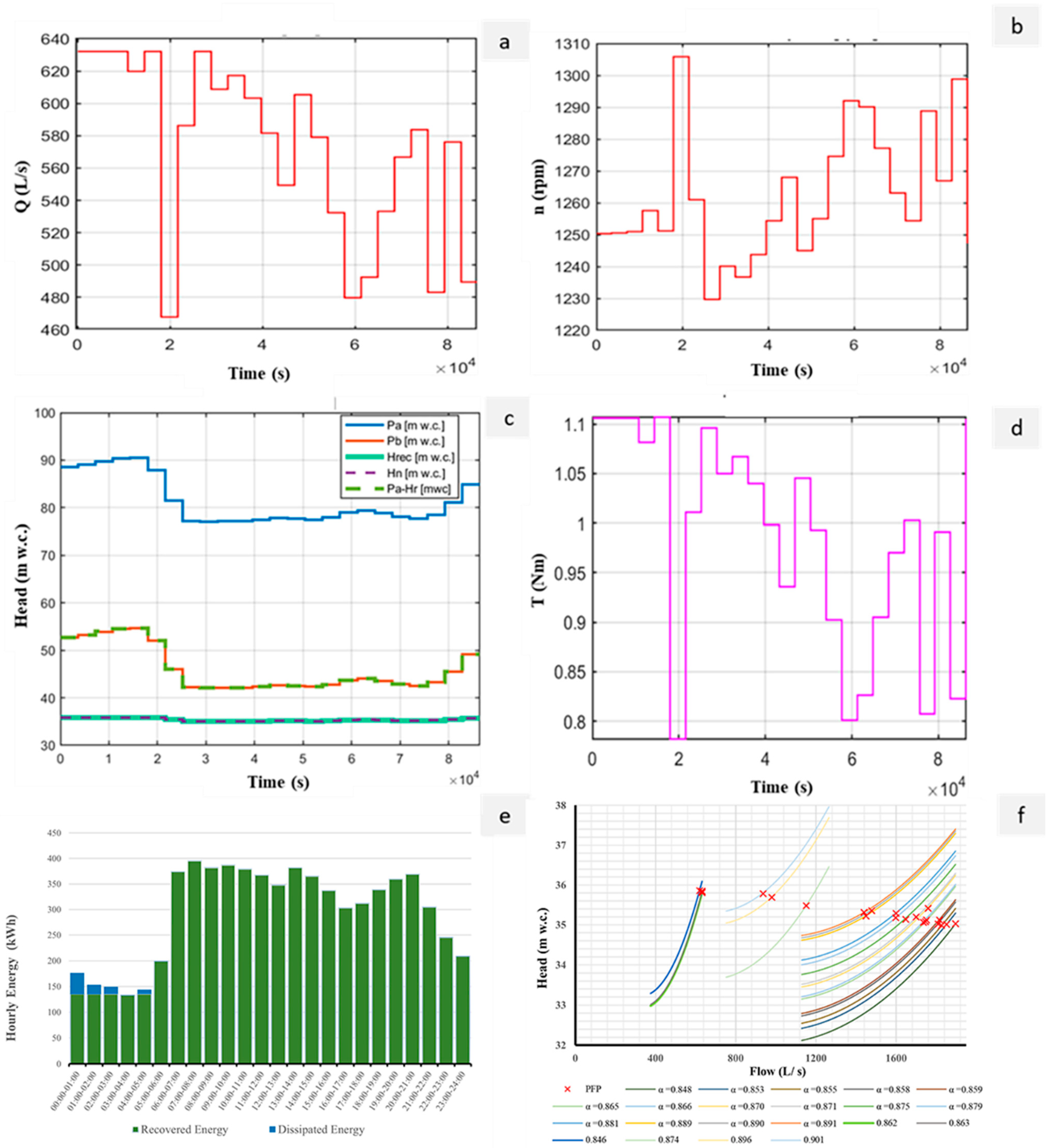
Figure 5a shows the operational flow of one machine during the entire simulation, in which instants are observed. Each PAT works between 468 and 632 L/s, considering that there are three machines connected in parallel. These machines operated with efficiency values between 0.61 and 0.65, and the recovered head oscillated between 33 and 35 m w.c.
Figure 5b shows the variation of the rotational speed to optimize the generated power over time. The rotational speed oscillated between 1229 and 1305 rpm over time. Figure 5c shows the temporal evolution of the heads during the optimization. These show the upstream (Pu) and downstream (Pd) pressures and the net head (Hn). Moreover, the figure shows the Hrt value, which never exceeded the net head value. Figure 5d shows the variation of the output torque value. It oscillates between 0.75 and 1.1 Nm over time, and this value is needed when the optimization of the generator is considered. The power on the shaft depends directly on the PAT’s efficiency and affects the electric motor efficiency, as well as the power and energy recovered by the machine. The generated power for each machine is between 107 and 145 kW.
Figure 5e shows the hourly energy analysis of the recovered and dissipated energies. The lowest recoverable energy value was 133 kWh, and it was recorded at 3 a.m., while the highest value was 395 kWh and was located at 7 a.m.
Otherwise, most of the time, the recoverable energy values remained close to the average value, which was 286 kWh. The daily recovered value was 7160 kWh, with an average efficiency value of 0.61. The complete optimization simulation represented 27.33% of the available energy, which was used to improve the efficiency ratio in the water system. These results are aligned with research published in [40]. However, this research enables the discretized flow over time, developing the selection and regulation of the machine under empirical expressions, which enables operation at the best point of the machine. This research improved the selection of the machines according to these expressions, but it is able to use any empirical expression, such as the equations proposed by [41].
Figure 5f shows the regulation strategy to guarantee the different operation points (PFP). It defines the recovered head curves as a function of the flow for the different values of α and their corresponding operating points for each of the PAT and their operating point for 1, 2, and 3 machines operating, respectively.
The analysis of the figure established the set values for the optimization of the hydraulic–electric regulation strategies. This set of regulations also defined the opening degrees of pressure-reduction valves (PRV), both serial and parallel. This last valve remained closed most of the time, and the highest degree of opening was 44.13%.
In the case of the serial PRV, it was always kept fully open because the recovery system optimization guarantees the downstream pressure defined by the operation restrictions.
The analysis considered the operation of the machine under steady conditions. The operation of the machine was not analyzed under unsteady conditions. However, when the flow change in water systems, the variation of the pressure is not significant if the flow does not totally stop. The operation and its consequences were analyzed by [42].
Figure 5 only shows an example of the operation with the optimization tool. The main advantage of this optimized tool is focused on the selection, regulation, and definition of the operation. The optimization procedure can choose the best machine and optimize its regulation to maximize the recovered energy while only knowing the flow over time and the downstream pressure constraint. It is a step ahead since the optimization tool defines the rotational speed and torque at each moment. These two variables are crucial to establishing the best electrical regulation when the machine is operating off-grid [43].

4. Conclusions

The lack of simulation and optimization tools for the management of recovery systems shows the need to implement models that enable the optimization of these energy facilities and the definition of setup regulation parameters for the electrical equipment. For this reason, this research proposes the implementation of an optimization model using the Simulink MATLAB code for its application.
This research defines an optimization strategy to establish the number of machines operating at any given time, the rotational speed, and the opening degree of the different PRVs to guarantee the hydraulic constraints of the system as well as maximize the recovered energy over time. The novelty of this research is focused on the integration of empirical methods, which could estimate the characteristic curves and optimize the operation and selection of the machines based on flow over time, as well as the frequency of these flows. The implementation tool is new and crucial to improving sustainability in water distribution systems. The proposed methodology is limited in terms of communication with the electronic regulation, which needs the output results of this methodology (i.e, torque and rotational speed in the axis of the machine) to develop optimization linked to electric loads and capacitance when the recovery system is installed off-grid. Future lines should be focused on integrating electric and water optimization into one tool.
The optimization management tool was applied in a real case in Valencia (Spain), and we showed the benefit of the model when variable flow occurs over time and under different constraints in terms of upstream and downstream pressure. The tool could be extrapolated for any water system when the water managers know the flow over time and the values of upstream and downstream pressure of the system. The model includes a preselection block to choose the pump necessary for operating as a turbine.
The implementation of hydraulic–electric regulation is a commitment to efficiency and sustainability. It should be incorporated into pressurized water systems to increase the generation of clean energy and improve the sustainability of the systems. The use of green or clean energies by the use of renewable systems allows us to reach different targets linked to the sustainable development goals and demonstrate the good practices of water managers in different supply systems.

Author Contributions

Conceptualization, P.A.L.-J. and M.P.-S.; methodology, M.A.G.E. and P.C.; software, writing—original draft preparation, M.A.G.E. and M.P.-S.; writing—review and editing, M.P.-S. and P.A.L.-J.; visualization M.P.-S.; supervision, P.A.L.-J. All authors have read and agreed to the published version of the manuscript.

Funding

Grant PID2020-114781RA-I00 was funded by MCIN/AEI/10.13039/501100011033.

Institutional Review Board Statement

Not applicable.

Informed Consent Statement

Not applicable.

Data Availability Statement

Not applicable.

Conflicts of Interest

The authors declare no conflict of interest.

Abbreviation

ParameterDefinitionUnits
QdDemanded flow.L/s
PuUpstream pressure.m w.c.
PdDownstream pressure.m w.c.
QBEPtFlow at the best efficiency point (BEP) of the machine in turbine mode.L/s
HBEPtRecovered head at the best efficiency point (BEP) of the machine in turbine mode.m w.c.
ηBEPtEfficiency at the best efficiency point (BEP) of the machines in turbine mode.%
nstSpecific number in turbine mode.m, kW
βQCoefficient used to determine flow from the machine in turbine mode to pump mode.Dimensionless
βHCoefficient used to determine head from the machine in turbine mode to pump mode.Dimensionless
QBEPpFlow at the best efficiency point (BEP) of the machine in pump mode.L/s
HBEPpHead at the best efficiency point (BEP) of the machine in pump mode.m w.c.
ηBEPEfficiency at the best efficiency point (BEP) of the machines in pump mode.%
nspSpecific number in pump mode.m, kW
QmintMinimum operating flow for the PAT.L/s
QmaxtMaximum operating flow for the PAT.L/s
NoNominal rotational speed of the PAT.rpm
nRotational speed of the PAT at a given moment.rpm
αFrequency inverter value setpoint for the rotational speed.%
αminMinimum frequency inverter value setpoint.%
αmaxMaximum frequency inverter value setpoint.%
lbLower bound of the range for determining the maximum power.%
ubUpper bound of the range for determining the maximum power.%
DiamPressure-reducing valve (PRV) diameter.mm
KvoFlow coefficient for the valve while fully open.m3/h/√Pa
gGravity acceleration.in m/s2
QtFlow rate turbinated by the PAT.L/s
QrtRatio between turbinated flow and flow at the BEP in turbine mode.Dimensionless
hRatio between recovered head and recovered head at the BEP in turbine mode.Dimensionless
eRatio between efficiency and the efficiency at the BEP in turbine mode.Dimensionless
HrtHead recovered by the PATm w.c.
ηtEfficiency of the PAT%
HnNet available head. Difference between upstream and downstream pressures.m w.c.
MPMechanical power generated by the PAT.kW
EPElectrical power generated by the generator.kW
γSpecific weight of the fluid.kN/m3
ηelecEfficiency of the electrical generator.%
TTorque produced by the PAT.Nm
CCoefficient representing the error of the estimated values of q and h.Dimensionless
qError of the estimated flow concerning the selection flow.%
hError of the estimated head for the selection head.%
iCounter value used in the tool used for determining the number of PATs being evaluated.Dimensionless

References

  1. Corcoran, L.; Coughlan, P.; McNabola, A. Energy Recovery Potential Using Micro Hydropower in Water Supply Networks in the UK and Ireland. Water Supply 2013, 13, 552–560. [Google Scholar] [CrossRef]
  2. Del Borghi, A.; Moreschi, L.; Gallo, M. Circular Economy Approach to Reduce Water–Energy–Food Nexus. Curr. Opin. Environ. Sci. Health 2020, 13, 23–28. [Google Scholar] [CrossRef]
  3. Kanakoudis, V.; Tsitsifli, S.; Samaras, P.; Zouboulis, A.; Demetriou, G. (PDF) Developing Appropriate Indicators for Urban Water Supply Systems Evaluation across the Mediterranean. Available online: https://www.researchgate.net/publication/258286246_Developing_appropriate_Indicators_for_urban_water_supply_systems_evaluation_across_the_Mediterranean (accessed on 21 February 2022).
  4. Kuriqi, A.; Pinheiro, A.N.; Sordo-Ward, A.; Bejarano, M.D.; Garrote, L. Ecological impacts of run-of-river hydropower plants—Current status and future prospects on the brink of energy transition. Renew. Sustain. Energy Rev. 2021, 142, 110833. [Google Scholar] [CrossRef]
  5. Kuriqi, A.; Pinheiro, A.N.; Sordo-Ward, A.; Garrote, L. Influence of hydrologically based environmental flow methods on flow alteration and energy production in a run-of-river hydropower plant. J. Clean. Prod. 2019, 232, 1028–1042. [Google Scholar] [CrossRef]
  6. Grubic, T.; Varga, L.; Hu, Y.; Tewari, A. Micro-Generation Technologies and Consumption of Resources: A Complex Systems’ Exploration. J. Clean. Prod. 2020, 247, 119091. [Google Scholar] [CrossRef]
  7. Reigstad, T.I.; Uhlen, K. Optimized Control of Variable Speed Hydropower for Provision of Fast Frequency Reserves. Electr. Power Syst. Res. 2020, 189, 106668. [Google Scholar] [CrossRef]
  8. Morani, M.; Carravetta, A.; del Giudice, G.; McNabola, A.; Fecarotta, O. A Comparison of Energy Recovery by PATs against Direct Variable Speed Pumping in Water Distribution Networks. Fluids 2018, 3, 41. [Google Scholar] [CrossRef] [Green Version]
  9. Eshra, N.M.; Zobaa, A.F.; Abdel Aleem, S.H.E. Assessment of Mini and Micro Hydropower Potential in Egypt: Multi-Criteria Analysis. Energy Rep. 2021, 7, 81–94. [Google Scholar] [CrossRef]
  10. Tahani, M.; Kandi, A.; Moghimi, M.; Houreh, S.D. Rotational Speed Variation Assessment of Centrifugal Pump-as-Turbine as an Energy Utilization Device under Water Distribution Network Condition. Energy 2020, 213, 118502. [Google Scholar] [CrossRef]
  11. Alhejji, A.; Kuriqi, A.; Jurasz, J.; Abo-Elyousr, F.K. Energy harvesting and water saving in arid regions via solar PV accommodation in irrigation canals. Energies 2021, 14, 2620. [Google Scholar] [CrossRef]
  12. Stefanizzi, M.; Capurso, T.; Balacco, G.; Binetti, M.; Camporeale, S.M.; Torresi, M. Selection, Control and Techno-Economic Feasibility of Pumps as Turbines in Water Distribution Networks. Renew. Energy 2020, 162, 1292–1306. [Google Scholar] [CrossRef]
  13. Stepanoff, A.J. Centrifugal and Axial Flow Pumps: Theory, Design, and Application; John Wiley: New York, NY, USA, 1957. [Google Scholar]
  14. Childs, S.M. Convert pumps to turbines and recover HP. Hydrocarb. Processing Pet. Refin. 1962, 41, 173–174. [Google Scholar]
  15. Grover, K.M. Conversion of Pumps to Turbines. In GSA Inter Copr. Katonah; Katonah: New York, NY, USA, 1980. [Google Scholar]
  16. Sharma, K. Small Hydroelectric Projects-Use of Centrifugal Pumps as Turbines; Kirloskar Electric Co.: Bangalore, India, 1985. [Google Scholar]
  17. Alatorre-Frenk, C. Cost Minimisation in Micro-Hydro Systems Using Pumps-as-Turbines. Ph.D. Thesis, University of Warwick, Coventry, UK, 1994. [Google Scholar]
  18. Williams, A.A. The Turbine Performance of Centrifugal Pumps: A Comparison of Prediction Methods. Proc. Inst. Mech. Eng. Part A J. Power Energy 1994, 208, 59–66. [Google Scholar] [CrossRef]
  19. Fernández, J.; Blanco, E.; Parrondo, J.; Stickland, M.T.; Scanlon, T.J. Performance of a Centrifugal Pump Running in Inverse Mode. Proc. Inst. Mech. Eng. Part A J. Power Energy 2004, 218, 265–271. [Google Scholar] [CrossRef] [Green Version]
  20. Derakhshan, S.; Nourbakhsh, A. Theoretical, Numerical and Experimental Investigation of Centrifugal Pumps in Reverse Operation. Exp. Therm. Fluid Sci. 2008, 32, 1620–1627. [Google Scholar] [CrossRef]
  21. Páscoa, J.C.; Silva, F.J.; Pinheiro, J.S.; Martins, D.J. A New Approach for Predicting PAT-Pumps Operating Point from Direct Pumping Mode Characteristics. JSIR 2012, 71, 144–148. Available online: http://nopr.niscair.res.in/handle/123456789/13492 (accessed on 11 April 2022).
  22. Rossi, M.; Renzi, M. A General Methodology for Performance Prediction of Pumps-as-Turbines Using Artificial Neural Networks. Renew. Energy 2018, 128, 265–274. [Google Scholar] [CrossRef]
  23. Macías Ávila, C.A.; Sánchez-Romero, F.J.; López-Jiménez, P.A.; Pérez-Sánchez, M. Definition of the Operational Curves by Modification of the Affinity Laws to Improve the Simulation of PATs. Water 2021, 13, 1880. [Google Scholar] [CrossRef]
  24. Delgado, J.; Ferreira, J.P.; Covas, D.I.C.; Avellan, F. Variable Speed Operation of Centrifugal Pumps Running as Turbines. Experimental Investigation. Renew. Energy 2019, 142, 437–450. [Google Scholar] [CrossRef]
  25. Carravetta, A.; del Giudice, G.; Fecarotta, O.; Ramos, H. PAT Design Strategy for Energy Recovery in Water Distribution Networks by Electrical Regulation. Energies 2013, 6, 411–424. [Google Scholar] [CrossRef] [Green Version]
  26. Kandi, A.; Moghimi, M.; Tahani, M.; Derakhshan, S. Optimization of Pump Selection for Running as Turbine and Performance Analysis within the Regulation Schemes. Energy 2021, 217, 119402. [Google Scholar] [CrossRef]
  27. Crespo Chacón, M.; Rodríguez Díaz, J.; García Morillo, J.; McNabola, A. Pump-as-Turbine Selection Methodology for Energy Recovery in Irrigation Networks: Minimising the Payback Period. Water 2019, 11, 149. [Google Scholar] [CrossRef] [Green Version]
  28. Rodríguez-Pérez, Á.; Pulido-Calvo, I.; Cáceres-Ramos, P. A Computer Program to Support the Selection of Turbines to Recover Unused Energy at Hydraulic Networks. Water 2021, 13, 467. [Google Scholar] [CrossRef]
  29. Venturini, M.; Manservigi, L.; Alvisi, S.; Simani, S. Development of a Physics-Based Model to Predict the Performance of Pumps as Turbines. Appl. Energy 2018, 231, 343–354. [Google Scholar] [CrossRef]
  30. Reigstad, T.I.; Uhlen, K. Nonlinear Model Predictive Control of Variable Speed Hydropower for Provision of Fast Frequency Reserves. Electr. Power Syst. Res. 2021, 194, 107067. [Google Scholar] [CrossRef]
  31. Alberizzi, J.C.; Renzi, M.; Nigro, A.; Rossi, M. Study of a Pump-as-Turbine (PaT) speed control for a Water Distribution Network (WDN) in South-Tyrol subjected to high variable water flow rates. Energy Procedia 2018, 148, 226–233. [Google Scholar] [CrossRef]
  32. Rossi, M.; Nigro, A.; Pisaturo, G.R.; Renzi, M. Technical and economic analysis of Pumps-as-Turbines (PaTs) used in an Italian Water Distribution Network (WDN) for electrical energy production. Energy Procedia 2019, 158, 117–122. [Google Scholar] [CrossRef]
  33. Nabil, T.; Alhaddad, F.; Dawood, M.; Sharaf, O. Experimental and numerical investigation of flow hydraulics and pipe geometry on leakage behaviour of laboratory water network distribution systems. J. Adv. Res. Fluid Mech. Therm. Sci. 2020, 75, 20–42. [Google Scholar] [CrossRef]
  34. Hòa, P.T.; Mogoş-Kirner, M.; Cristea, V.M.; Alexandra, C.; Agachi, P.Ş. Simulation and control of floods in a water network. Case study of Jijia River Catchment. Environ. Eng. Manag. J. (EEMJ) 2017, 16, 587–595. [Google Scholar]
  35. Kuriqi, A. Simulink application on dynamic modeling of biological waste water treatment for aerator tank case. Int. J. Sci. Technol. Res. 2014, 3, 69–72. [Google Scholar]
  36. Camilo Rosado, L.; López-Jiménez, P.; Sánchez-Romero, F.-J.; Conejos Fuertes, P.; Pérez-Sánchez, M. Applied Strategy to Characterize the Energy Improvement Using PATs in a Water Supply System. Water 2020, 12, 1818. [Google Scholar] [CrossRef]
  37. Pérez-Sánchez, M.; Sánchez-Romero, F.J.; Ramos, H.M.; López-Jiménez, P.A. Improved Planning of Energy Recovery in Water Systems Using a New Analytic Approach to PAT Performance Curves. Water 2020, 12, 468. [Google Scholar] [CrossRef] [Green Version]
  38. Plua, F.A.; Sánchez-Romero, F.-J.; Hidalgo, V.; López-Jiménez, P.A.; Pérez-Sánchez, M. New Expressions to Apply the Variation Operation Strategy in Engineering Tools Using Pumps Working as Turbines. Mathematics 2021, 9, 860. [Google Scholar] [CrossRef]
  39. UNE-EN 60034-30-1:2014 (Ratificada) Máquinas Eléctricas Rotativas. Available online: https://www.une.org/encuentra-tu-norma/busca-tu-norma/norma?c=N0053096 (accessed on 22 February 2022).
  40. McNabola, A.; Coughlan, P.; Corcoran, L.; Power, C.; Prysor Williams, A.; Harris, I.; Gallagher, J.; Styles, D. Energy Recovery in the Water Industry Using Micro-Hydropower: An Opportunity to Improve Sustainability. Water Policy 2014, 16, 168–183. [Google Scholar] [CrossRef]
  41. Novara, D.; McNabola, A. A Model for the Extrapolation of the Characteristic Curves of Pumps as Turbines from a Datum Best Efficiency Point. Energy Convers. Manag. 2018, 174, 1–7. [Google Scholar] [CrossRef]
  42. Pérez-Sánchez, M.; López-Jiménez, P.A.; Ramos, H.M. PATs operating in water networks under unsteady flow conditions: Control valve manoeuvre and overspeed effect. Water 2018, 10, 529. [Google Scholar] [CrossRef] [Green Version]
  43. Capelo, B.; Pérez-Sánchez, M.; Fernandes, J.F.P.; Ramos, H.M.; López-Jiménez, P.A.; Branco, P.J.C. Electrical Behaviour of the Pump Working as Turbine in off Grid Operation. Appl. Energy 2017, 208, 302–311. [Google Scholar] [CrossRef]
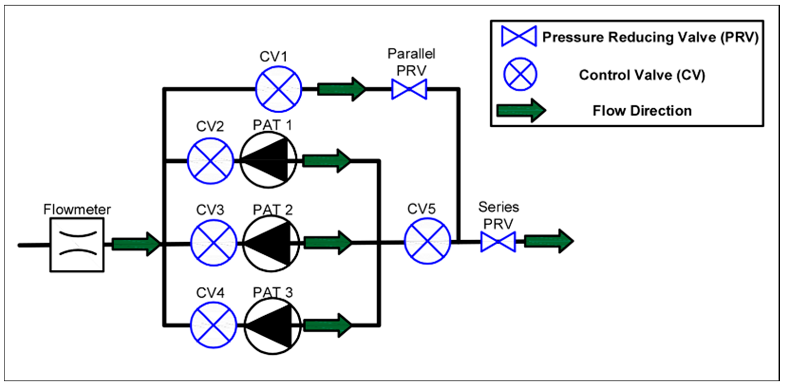
Figure 1. Hydraulic model layout.
Water 14 01535 g001
Figure 2. Proposed methodology for the analysis of the regulation in an energy-recovery system.
Water 14 01535 g002
Figure 3. The layout of the case study scenario. ΔH represents the net hydraulic jump available.
Water 14 01535 g003
Figure 4. (a) Total daily recovered energy for preselected machines; (b) block structure in Simulink MATLAB; (c) head and efficiency curve for preselected PAT; (d) efficiency generator curves according to the power to define the efficiency of the PAT generator adapted of the data from [39].
Water 14 01535 g004
Figure 5. (a) Flow over time; (b) rotational speed of the machine over time; (c) pressures and Head over time; (d) torque over time; (e) hourly energy; (f) regulation of the recovery system.
Water 14 01535 g005
Table 1. Data recovered from the case study.
Time Interval (Δt = 60 min)Qd (L/s)Pu (m w.c.)Pd (m w.c.)
00:00–01:00749.0388.5352.71
01:00–02:00684.5989.6753.82
02:00–03:00672.7089.8954.03
03:00–04:00619.7990.8754.99
04:00–05:00655.8690.1954.33
05:00–06:00936.0285.5249.79
06:00–07:001758.9777.4742.36
07:00–08:001896.6876.9541.98
08:00–09:001825.8777.1842.14
09:00–10:001851.9177.0942.08
10:00–11:001809.2077.2542.19
11:00–12:001745.4977.5342.41
12:00–13:001648.5278.0542.84
13:00–14:001816.7677.2242.17
14:00–15:001736.8277.5642.44
15:00–16:001597.2378.3843.12
16:00–17:001439.1779.5944.20
17:00–18:001477.3379.2743.91
18:00–19:001599.6478.3743.11
19:00–20:001700.3277.7642.60
20:00–21:001751.7777.5042.39
21:00–22:001449.6079.5044.12
22:00–23:001151.9282.5946.99
23:00–24:00979.2984.8949.18
Minimum value619.7976.9541.98
Maximum value1896.6890.8754.99
Mean Value1398.1081.2045.83
Standard Deviation455.895.084.77
Table 2. Preselected machines in turbine mode and value of C.
No.ManufacturerModelQBEPt(L/s)HBEPt
(m w.c.)
ηBEPt
(%)
nst
(m, kW)
Δq
(%)
Δh
(%)
C
1IDEAL350–430809.5344.470.67175.75831.2826.520.98
2IDEAL350–360652.8543.040.67169.7275.8722.440.95
3KSB350–430842.4248.140.6472.8236.6136.971.23
4KSB350–430768.8743.630.64087.98424.6824.130.81
Publisher’s Note: MDPI stays neutral with regard to jurisdictional claims in published maps and institutional affiliations.