3.1.2. Effect of Ultrasound on Membrane Performance
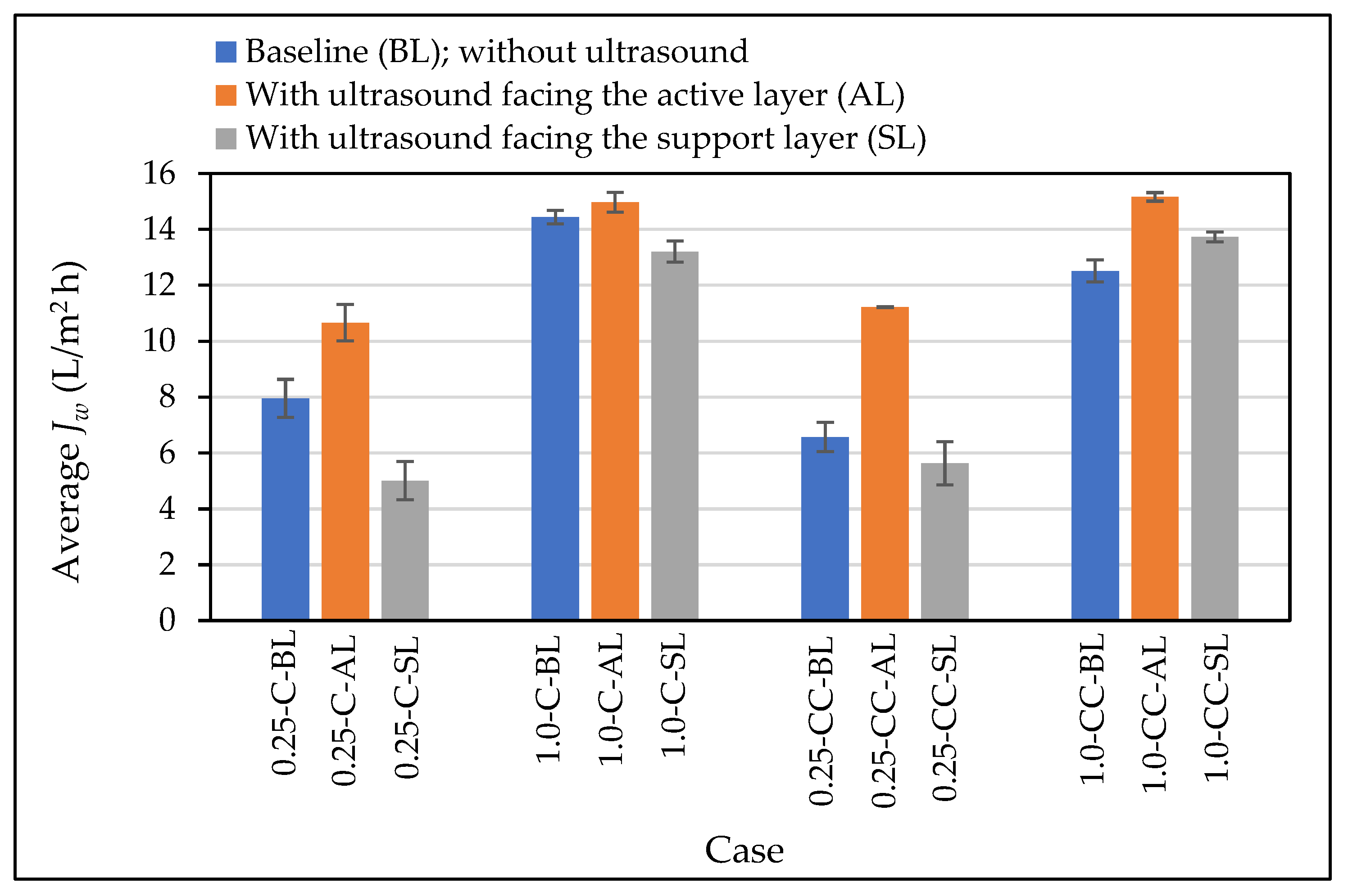
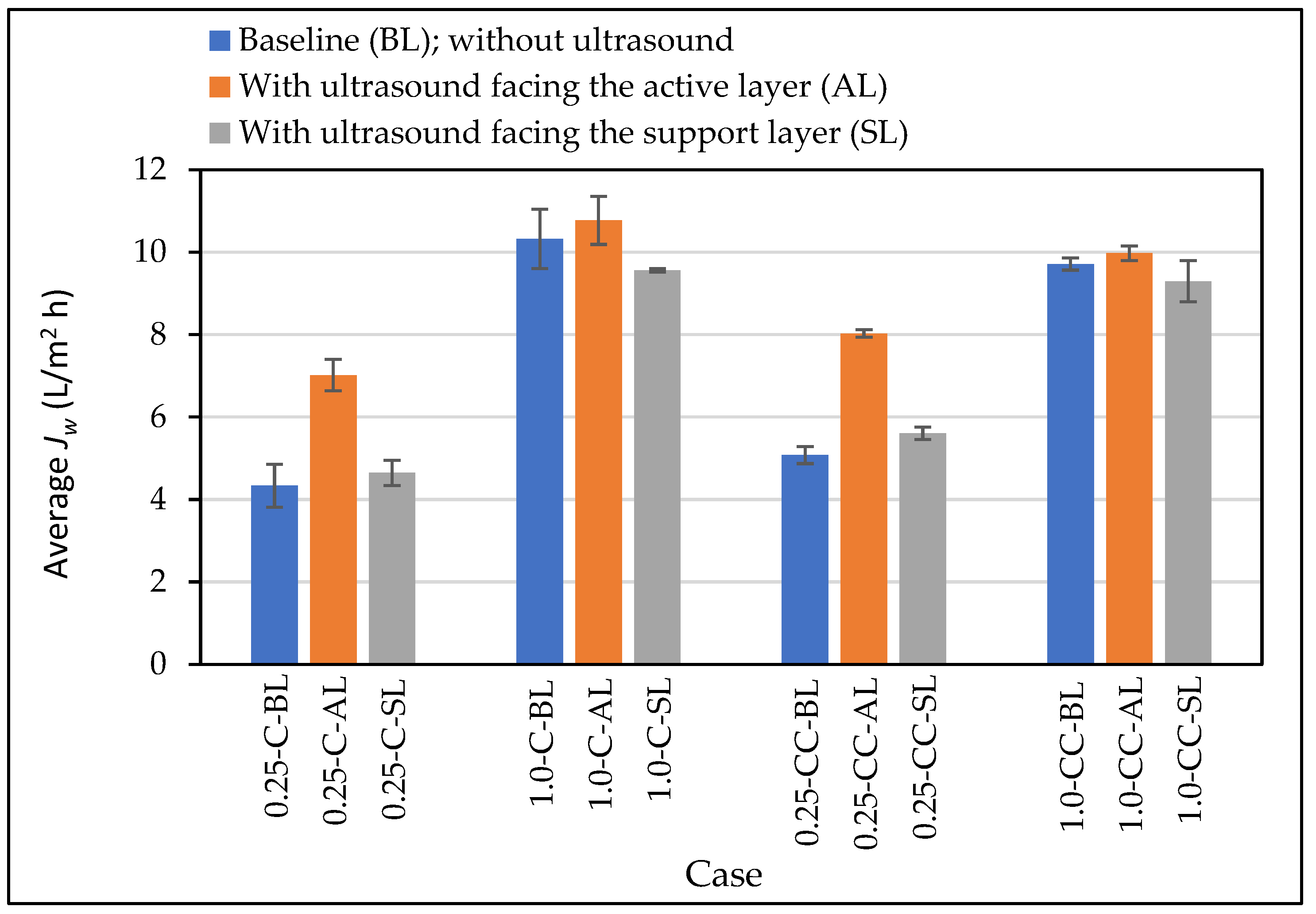
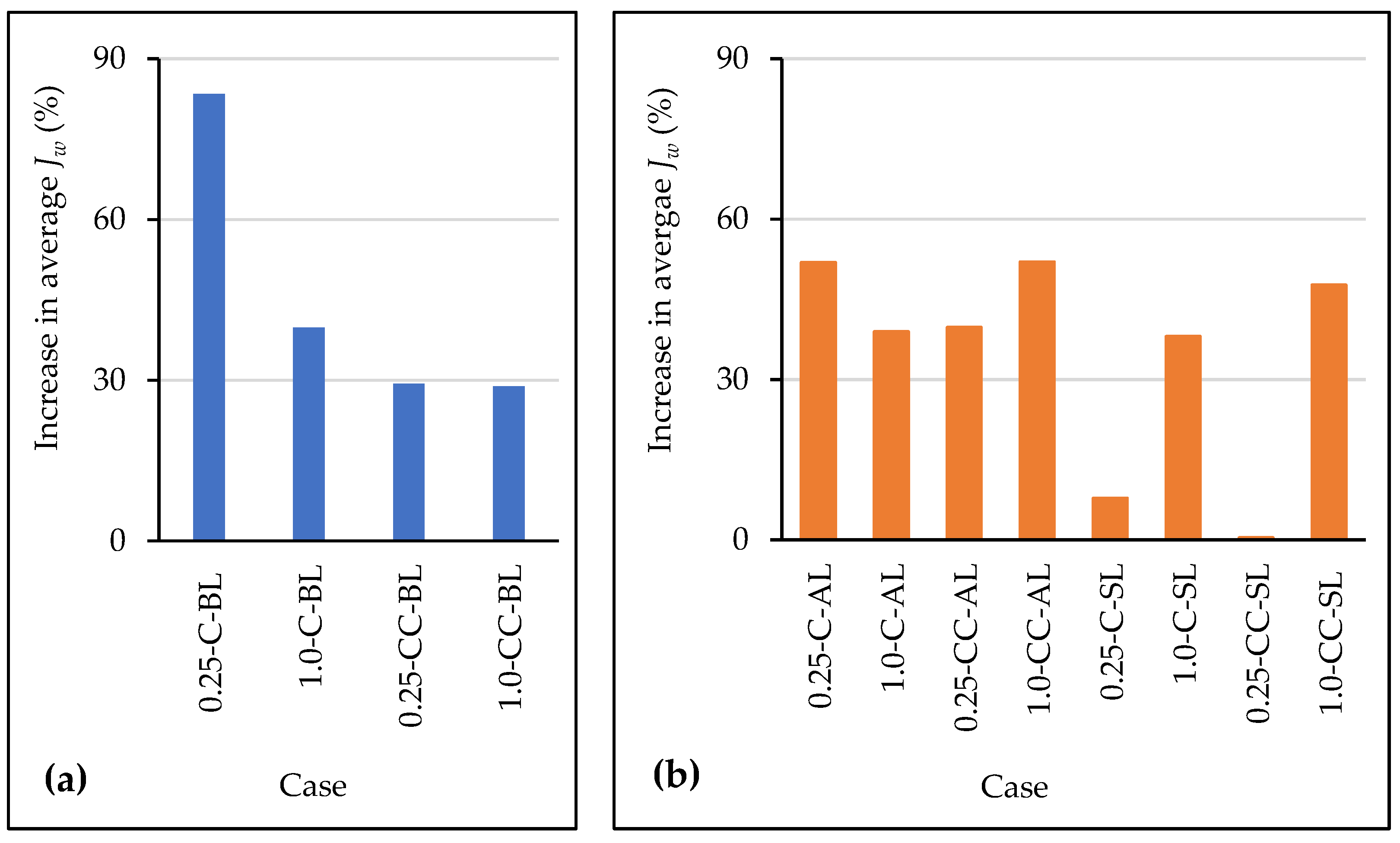
The effect of ultrasound on the membrane average water flux was investigated at different testing arrangements, namely 0.25-C-AL, 1.0-C-AL, 0.25-CC-AL, 1.0-CC-AL, 0.25-C-SL, 1.0-C-SL, 0.25-CC-SL, and 1.0-CC-SL. The results are presented in
Figure 3 along with those obtained under baseline conditions. Compared to the baseline results, the average water flux increased when the ultrasound source faced the membrane active layer. Moreover, the average water flux was lower except for the case of 1.0-CC- SL, when the ultrasound source faced the membrane support layer.
The most significant water flux improvement due to the use of ultrasound was observed for the case of 0.25-CC-AL (
Figure 3), where the average flux increased from 6.57 L/m
2·h, under baseline conditions, to 11.22 L/m
2·h, when ultrasound was applied (i.e., 70.8% improvement). For the case of 0.25-C-AL, the average water flux increased from a baseline value of 7.95 L/m
2·h to 10.66 L/m
2·h by applying ultrasound (an improvement of 34.0%). Applying the ultrasound in the case of 1.0-CC-AL caused an improvement in the average water flux by 21.2% (the average water flux increased from 12.51 to 15.16 L/m
2·h). However, for the case of 1.0-C-AL, there was only a slight increase in the average water flux (from 14.44 to 14.97 L/m
2·h), which is considered insignificant given the overlap between the range of the average water flux with and without the use of ultrasound for that case.
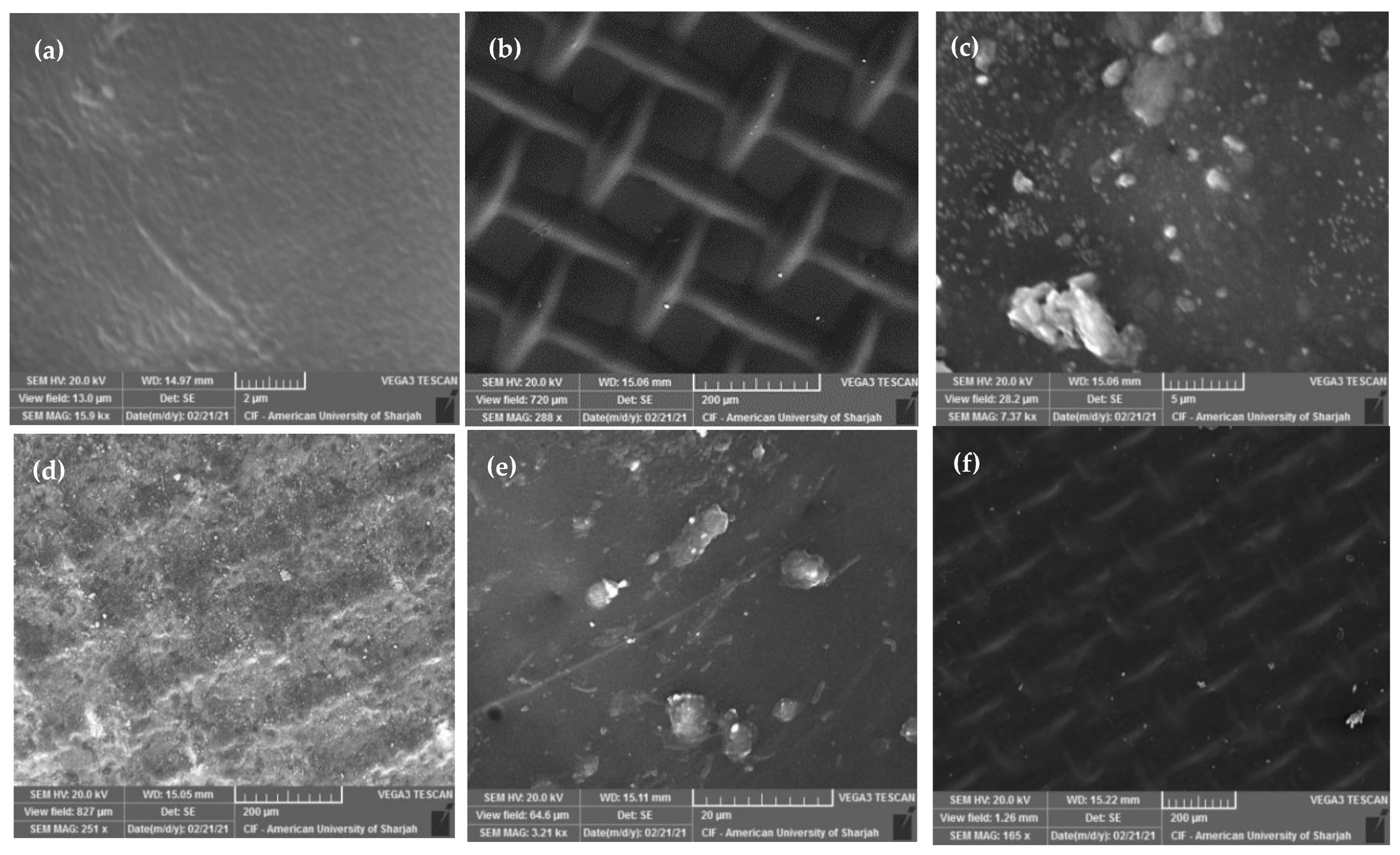
When the ultrasound source was in the direction of the membrane active layer, it was observed that the highest water flux improvement caused by the ultrasound was more significant for the cases with the low CFV. This could be mainly attributed to the formation of fouling and scaling layers, which are caused by the presence of sodium alginate and calcium sulfate in the feed solution, and the initiation of ECP that was promoted during the low CFV at the membrane active layer side. Imposing the ultrasound reduces the formation of these layers, which ultimately enhances the membrane water flux. Moreover, the effect of the ultrasound on the membrane water flux improvement at high velocity was less significant compared to that observed at low velocity. This could be due to the effect of the high CFV on the membrane surface cleaning and its role in minimizing the ECP. Examples of the SEM images for fouling membranes at low and high CFV are shown in
Figure 4. The figure demonstrates the increase in membrane fouling with the ultrasound facing the support layer and at low CFV (
Figure 4c,d) as opposed to when the ultrasound faces the active layer with high CFV (
Figure 4e,f).
Changes in the flow configuration at similar CFVs for the case with the ultrasound source facing the active layer caused a very low impact on flux enhancement. This could be attributed to the small dimensions of the testing cell, where the effect of changing the flow configuration does not appear to be clearly noticeable along the selected membrane dimensions. This agrees with the findings of Phuntsho et al. [
38], who found no significant effect on the water flux due to the change in the flow configuration, which was also attributed to the small size of the testing cell.
Considering the feed solution characteristics of having fouling and scaling materials, the active layer of the FO membrane is exposed to fouling problems that ultimately cause flux reduction due to cake/gel layer formation (external fouling). In this study, both sodium alginate and calcium sulfate are present in the feed solution. When alginate interacts with the solution containing calcium sulfate, a layer of calcium alginate is immediately formed to surround the sodium alginate surface. The negatively charged sulfate ions in the solution are attracted by the calcium ions, resulting in the formation of a new layer of SO
42− that promotes crystal formation and acts as a nucleus around the sodium alginate molecules, which forms a combined network of calcium sulfate crystals and an alginate gel layer [
39]. This compacted gel layer promotes membrane surface fouling and reduces water flux [
30,
40,
41]. Moreover, the high concentration of solutes in the feed solution adjacent to the membrane active layer, compared to the feed solution bulk concentration, results in the formation of an ECP boundary layer on the membrane active layer that reduces the osmotic pressure difference [
42]. In addition, an accelerated cake-enhanced osmotic pressure (CEOP), due to reverse solute flux, causes the formation of a thick fouling layer on the membrane surface due to the unavailability of hydraulic pressure. The formation of the CEOP causes flux reduction by increasing the system resistance and decreasing the net osmotic pressure driving force due to the trapped solute particles between the membrane active layer and the formed fouling layer [
43,
44]. This is in agreement with Heikkinen et al., who observed flux enhancement upon applying ultrasound on the CTA membrane active layer [
28].
It is reported that the use of ultrasound minimizes the impact of ECP by (1) reducing solute concentration at the membrane boundary layer, (2) reducing the external fouling effect by breaking the fouling (sulfate crystals and alginate gel) layer formed [
29], and (3) detaching the deposited substances on the membrane active layer [
45]. This significantly reduces the system resistance and increases the membrane performance accordingly. Ultrasound waves produce a high mechanical power through a physical medium (water) by a little mechanical movement [
22]. The propagation of sound waves starts by a group of cyclic compression and rarefaction waves that may cause physical/chemical changes at different levels and magnitudes in the medium. Due to the compression and rarefaction cycles, the medium molecules are exposed to a positive and negative acoustic pressure that creates bubble cavitation [
46]. Bubbles keep growing to a certain size and then collapse. Bubbling collapse produces extreme pressure, up to 1000 atm, and localized temperature up to 5000 K [
26,
47]. This phenomenon (local hotspots) enhances the heat transfer rates within the feed solution and promotes the creation of a highly turbulent area [
26] that can be used to detach the deposited particles on the membrane surface and, thus, enhances the performance by increasing water flux. Moreover, the observed flux enhancement in the ultrasound source facing the active layer could be also attributed to the ultrasound effect of generating local heating zones on the membrane surface that could accelerate transfer rates.
The use of ultrasound could assist in membrane surface cleaning through mechanisms such as acoustic streaming, microstreaming, microstreamers, microjets, and shock waves [
48]. The acoustic streaming mechanism enhances membrane cleaning by transmitting acoustic energy through the feed solution to produce liquid flow which is obstructed, causing unidirectional liquid flow waves with a flow velocity that reaches up to 10 m/s parallel to the surface of the deposits, which may help in foulant removal [
26]. Microstreamers, on the other hand, are generated by the superimposition of the ultrasound waves produced by the transducer and the waves reflected from the membrane surface to create standing (stationary) waves. The cavitation bubbles are attracted by the standing wave antinodes and structured in a certain path where the bubble size increases while traveling toward the antinodes located at the membrane surface. Once the antinodes reach the fouled membrane surface, bubbles are formed, causing drag and a detach effect on the particles deposited on the membrane surface [
22,
26,
49]. Microstreaming may also play a role in membrane fouling cleaning by creating shear/drag forces used to detach the foulants from the membrane surface. During the compression and expansion cycles, a rapid fluctuation (in magnitude and direction) occurs in the fluid movement caused by oscillation in the cavitation bubbles. The shrinking effect of the cavitation bubbles pulls the liquid molecules away from the membrane surface, while the expanding effect pushes the molecules to the membrane surface, causing shear and drag forces needed for foulant removal from the membrane surface [
50].
Microjets produced by the ultrasound is another mechanism that can clean the fouled membrane surface by creating the pitting and scrubbing effects on the fouling layer. Microjets create turbulent zones in the feed solution by their ability to attain high-velocity fluid jets (100–200 m/s) due to the asymmetric cavitation bubble collapse [
22]. Shock waves produced by the ultrasound also show the capability to clean the membrane surface and provide high pressure toward the membrane active layer that ultimately contributes to water flux enhancement. Shock waves are generated continuously during the compression and expansion cycles. When the cavitation bubble reaches its minimum size, at the end of the compression cycle, the cavitation bubbles reach a sudden halt causing liquid molecules, moved to the bubbles, to reflect with high pressure toward the membrane surface [
26,
50].
It should be indicated that in the FO membrane system, two main forces are applied to the feed solution particles. The first one is the effective driving force (perpendicular to the membrane surface) dictated by the osmotic pressure difference between the feed and draw solutions, which causes the transfer of water molecules from the feed solution toward the draw solution side and forces the feed solution foulant particles to deposit on the membrane surface. The second one, which moves the feed solution molecules toward the bulk of the solution, is the shear force (moved tangentially to the membrane surface) caused by the CFV [
51]. Applying ultrasound waves on the membrane active layer side generates other forces in the same direction of the system, driving forces that help in pushing the water molecules toward the draw solution side, which ultimately enhances water flux.
The increase in flux with the use of ultrasound at the membrane active layer side is in agreement with Heikkinen et al., who observed flux enhancement upon applying ultrasound on the CTA membrane active layer [
28]. However, Heikkinen et al. [
28] found better flux enhancement when the ultrasound source faced the membrane support layer. This is in contrary to the findings of this study. As shown in
Figure 3, there is a decrease in the average water flux, compared to the baseline conditions, when using the ultrasound with the membrane support layer facing the draw solution for all the considered cases except the case of 1.0-CC-SL, which showed an increase of around 9.7%. For the case of 0.25-C-SL, the average flux decreased from 7.95 to 5.01 L/m
2·h, which represents 37.1% flux reduction. For the case of 1.0-C-SL and 0.25-CC-SL, the average water flux decreased from 14.44 and 6.57 L/m
2·h to 13.20 and 5.63 L/m
2·h, respectively, with respect to the baseline. The decrease in the water flux could be attributed to reverse solute flux caused by the application of the ultrasound toward the membrane support layer. Reverse solute flux promotes transfer of the solute from the draw solution toward the feed solution. This agrees with the findings of Qasim et al. [
26] and Heikkinen et al. [
28], who reported that the application of ultrasound on the membrane support layer increases the reverse solute flux. The reverse solute flux from the draw solution side toward the feed solution side complicates the fouling layer and worsens the ECP by trapping the draw solution solute particles between the membrane surface and the fouling layer, thus inducing the formation of an accelerated CEOP that causes a significant flux decline [
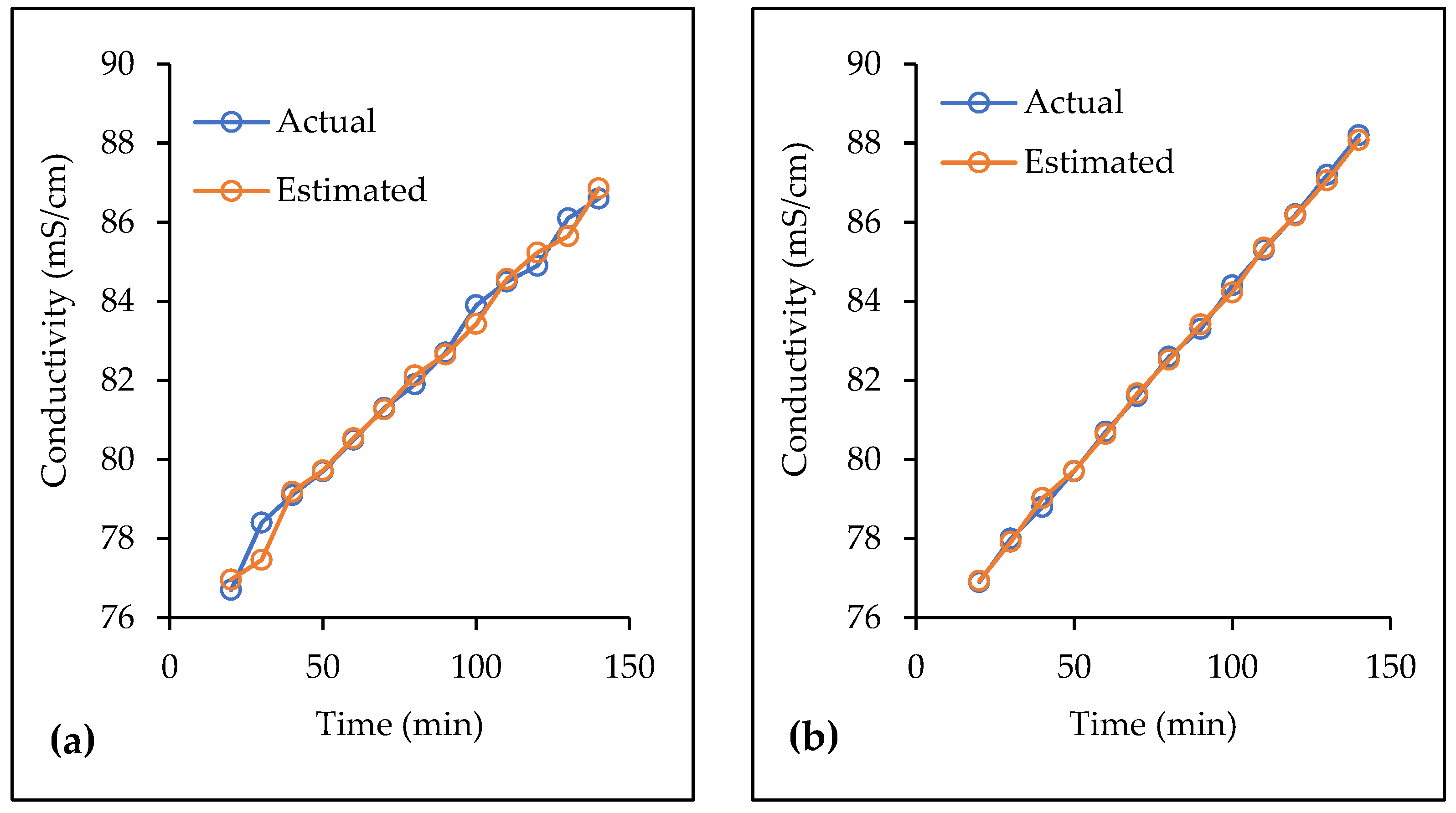
44]. For this reason, the reverse solute flux did not reveal a significant change in the feed solution conductivity measurements, as shown in
Figure 5. This figure shows representative examples of the relation between the measured and the estimated conductivity values during the time of the experiment. The estimated conductivity values were obtained through the application of mass balance on conductivity, assuming no solutes transfer occurs from the feed solution to the draw solution side (i.e., water molecules were only transferred). It should be noted that NaCl shows a high potential for reverse solute flux due to its small ionic size [
52,
53]. Moreover, the turbulence zones and their associated forces generated by the ultrasound in the opposite direction of the water molecules transfer (from the feed to the draw solution) may also hinder the water transfer process, especially when the membrane active layer is exposed to fouling and ECP conditions. Applying ultrasound toward the support layer side would not have a powerful impact on reducing the formation of the fouling layer on the membrane active layer. On the contrary, weak ultrasound waves received at the active layer side could have caused the formed fouling layer to be denser and more spread on the surface, which negatively affected the membrane flux relative to the baseline conditions.
The formation of a fouling thick gel layer and the ECP effect at the surface of the membrane active layer create an additional resistance to the system. Thus, considering the flow resistance created by the ultrasound effect in the opposite side (draw solution side), the available driving force (osmotic pressure difference) would not be adequate to overcome these resistances. This is consistent with the results observed for the cases of 0.25-C-SL and 0.25-CC-SL, where the effect of fouling is more severe at low CFV. For the case of 1.0-C-SL, the adverse effect of using ultrasound facing the support layer on the water flux was less pronounced compared to the case at low CFV (0.25-C-SL). It is possible that the high CFV minimizes the effect of fouling and ECP at the active layer, and it induces mixing at the support layer assisted by the impact of the ultrasound for minimizing the ICP [
54], yet the flux was lower than the corresponding value obtained without the use of ultrasound (1.0-C-BL).
A water flux enhancement of around 9.7% was observed for the case of 1.0-CC-SL, where the average water flux increased from 12.51 L/m
2·h under baseline conditions to 12.73 L/m
2·h with the use of ultrasound (
Figure 3). This is due to the combined effects of the ultrasound, the high CFV, and the counter-current flow configuration. The use of ultrasound minimizes the effect of ICP by mixing the produced permeate water with the draw solution that ultimately enhances the draw solution diffusion rate and, thus, increases the water flux [
25]. The high CFV contributes to the low impact of resistance layers (fouling and ECP) and minimizes the mass transfer boundary layer (i.e., becomes thinner) at the membrane surface [
55]. Moreover, using the counter-current configuration resulted in lowering the fouling effect at the membrane active layer surface [
56]. In this case (1.0-CC-SL), it is expected that the combined effect of high CFV and counter-current flow configuration leads to reducing the system resistance and thus facilitates the effort of the ultrasound in minimizing the ICP effect. Because of that, the system driving force was able to overcome the resistance produced by the ultrasound that was translated into flux enhancement.


