Article

A Coupled SWAT-AEM Modelling Framework for a Comprehensive Hydrologic Assessment

1
Environmental and Water Resources Engineering Division, Department of Civil Engineering, IIT Madras, Chennai 600036, India
2
Department of Ecosystem Sciences and Management and Biological and Agricultural Engineering, Texas A&M University, College Station, TX 78224, USA
*
Author to whom correspondence should be addressed.
Water 2022, 14(17), 2753; https://doi.org/10.3390/w14172753
Submission received: 22 July 2022 / Revised: 31 August 2022 / Accepted: 1 September 2022 / Published: 4 September 2022
(This article belongs to the Section Hydrology)

Abstract

:
This study attempts to integrate a Surface Water (SW) model Soil and Water Assessment Tool (SWAT) with an existing steady-state, single layer, unconfined heterogeneous aquifer Analytic Element Method (AEM) based Ground Water (GW) model, named Bluebird AEM engine, for a comprehensive assessment of SW and GW resources and its management. The main reason for integrating SWAT with the GW model is that the SWAT model does not simulate the distribution and dynamics of GW levels and recharge rates. To overcome this issue, often the SWAT model is coupled with the numerical GW model (either using MODFLOW or FEFLOW), wherein the spatial and temporal patterns of the interactions are better captured and assessed. However, the major drawback in integrating the two models (SWAT with—MODFLOW/FEM) is its conversion from Hydrological Response Unit’s (HRU)/sub-basins to grid/elements. To couple them, a spatial translation system is necessary to move the inputs and outputs back and forth between the two models due to the difference in discretization. Hence, for effective coupling of SW and GW models, it may be desirable to have both models with a similar spatial discretization and reduce the need for rigorous numerical techniques for solving the PDEs. The objective of this paper is to test the proof of concept of integrating a distributed hydrologic model with an AEM model at the same spatial units, primarily focused on surface water and groundwater interaction with a shallow unconfined aquifer. Analytic Element Method (AEM) based GW models seem to be ideal for coupling with SWAT due to their innate character to consider the HRU, sub-basin, River, and lake boundaries as individual analytic elements directly without the need for any further discretization or modeling units. This study explores the spatio-temporal patterns of groundwater (GW) discharge rates to a river system in a moist-sub humid region with SWAT-AEM applied to the San Jacinto River basin (SJRB) in Texas. The SW-GW interactions are explored throughout the watershed from 2000–2017 using the integrated SWAT-AEM model, which is tested against stream flow and GW levels. The integrated SWAT-AEM model results show good improvement in predicting the stream flow (R2 = 0.65–0.80) and GW levels as compared to the standalone SWAT model. Further, the integrated model predicted the low flows better compared to the standalone SWAT model, thus accounting for the SW-GW interactions. Almost 80% of the stream network experiences an increase in groundwater discharge rate between 2000 and 2017 with an annual average GW discharge rate of 1853 Mm3/year. The result from the study seems promising for potential applications of SWAT-AEM coupling in regions with considerable SW-GW interactions.

1. Introduction

In developing countries, there exists a huge water demand due to the rapid expansion of population, urbanization, industrial growth, and agricultural production. Groundwater in rural areas is particularly vulnerable as the transfer of surface water rights to urban areas increases the reliance on groundwater resources, leading to a decrease in overall groundwater levels and groundwater storage [1]. Groundwater storage becomes depleted further due to inefficient surface irrigation practices. Additionally, in many regions of the world, the present scenario changes drastically as Ground Water (GW) supplants Surface Water (SW) as the preferred source of water in various sectors due to its easy access and inherently having beneficial properties in terms of water quality and quantity. Based on the hydrogeology and topography of a river basin, there would be an interaction between SW and GW. In the regions where the SW and GW interact, groundwater extractions are known to have a significant impact on stream flow during the lean season. The problems that groundwater managers often grapple with are:
(a)
How can we conserve and manage today’s SW/GW resources for the future?
(b)
How do we maintain the proper balance between both SW/GW systems for the long-term sustainability of water resources?
The above two questions are partially addressed by integrating the SW and GW models to better represent the real-world hydrological process interactions. The reason is that water in the hydrological cycle is in a continuum and hence, further development of one component could affect the other components in the hydrologic cycle. Previous studies in large-scale simulations include publications that mainly focused either on surface water resources [2,3,4] or on groundwater [5,6,7], with few applications of coupled models of surface water and groundwater [8]. Traditionally many watershed models have been applied to problems of SW management without considering GW in much detail. For example, in many SW models, the primary assumption is that the percolation from the soil profile is lost from the system, and thus GW processes are incorporated simplistically [3].
Similarly, GW models have been applied to aquifer management problems, ignoring SW management in greater detail [6]. Among all hydrologic models, one such popular SW hydrologic model is the Soil and Water Assessment Tool (SWAT), which has been adequately calibrated and validated across watersheds in arid [9,10], semi-arid [11,12], humid [13] and subhumid [14,15] regions around the world and found to simulate stream flow accurately in regions with minimal SW and GW interaction. However, the SWAT model has been assessed to lack the capability to simulate the spatial distribution of GW dynamics in regions dominated by SW and GW interaction [8,16,17,18,19]. This is because SWAT considers each HRU and sub-basins as a separate 1D unit, and hence the interaction of subsurface flow among neighboring HRUs and the sub-basin is not considered in the simulations. Furthermore, the spatial locations of each HRU within the sub-basins are not considered.
For addressing this disconnect and lacuna, with a maturing knowledge about the natural resource system, there has been a move towards developing and adopting a new holistic approach, in which SW and GW models are integrated for efficient water resource management [8]. In general, groundwater and surface interactions are classified into two categories: (1) short-term highly transient events, primarily responsible for stream flow peaks and (2) long-term and seasonal trends that control the average baseflow in stream networks [15]. To accurately simulate the water resources, a computer model which helps in quantifying them should be holistic and consider both surface water (SW) and groundwater (GW) together instead of treating them individually. Over the past two decades, the interactions between SW-GW models have increased and have been the subject of many studies [20,21,22,23]. Additionally, SW-GW modeling tools are undergoing a drastic change from traditional standalone model studies towards being an integrated part of comprehensive water resources assessment and act as an effective water management strategy in the water-stressed regions. However, linking both SW-GW in a model is often problematic because they use a different set of governing equations and different spatial and temporal discretization schemes.
Owing to a rapid increase in the growth of computing and the wide availability of computers and modeling software from the early 2000s, many physically based, fully integrated SW-GW models have been developed for water resource research and management [16,20]. The integrated models provide both detailed spatial and temporal descriptions of the basin-scale hydrologic cycle and can simulate a variety of state and flux variables and have been applied in various hydrology studies in different parts of the world [1,20,23,24,25,26,27,28,29,30]. Therefore, a variety of coupled SW and GW models have evolved over the years, such as GSFLOW [19], MIKE-SHE [23], and several SW models integrated into MODFLOW, such as MODBRANCH [28], SWATMOD [29], MODHMS [30], VIC-MODFLOW [16], and TOPMODEL-MODFLOW [31]. Some of the examples of loosely coupled SW and GW models are SWATMOD [32], etc. Among all the coupled SW-GW models, SWAT- MODFLOW integration has been successfully applied in many studies [20,28,29,30,31,32,33,34,35] and is widely in use all over the world.
The surface and shallow aquifer processes simulated in SWAT are based on Hydrologic Response Units (HRUs), which are conceptual units of homogeneous land use, soil and slope characteristics that extend below the surface to soil depth (Vadose zone). However, the major drawback of the SWAT model is that it considers each HRU and sub-basins as a separate 1D unit and hence the interaction of subsurface flow among neighboring HRU and sub-basin is not considered in the simulations. Additionally, SWAT has its own GW component module [17] which is a lumped model, and therefore, the model lacks in expressing the spatial distribution and dynamics in GW levels and recharge rates for watershed simulation. In fact, SWAT compares shallow aquifer depth with a threshold to estimate the river recharge, and it is not capable of considering the bottom elevation and aquifer depth to properly simulate recharge [11,22,31,33,35]. Hence, SWAT is often coupled with MODFLOW for simulating SW-GW interactions in watersheds. However, a critical stumbling block exists for integrating SWAT’s HRU based modeling elements with the numerical solutions of GW models, which are based on a regular or irregular grid-based discretization scheme. Since the method of domain discretization is different between SW and GW models, it is necessary to move the inputs and outputs back and forth between the two models. This translation system would often use an area-weighted averaging technique. Usually, it may be necessary to finely grid the GW model domain to transfer the data between the two models without loss of information. This results in a substantial CPU time for running the coupled model. Generally, GW models require longer time steps which in turn causes a loss of accuracy by over-averaging the river stage values and for the modeling river system, the shorter time step is required which in turn leads to an increase in computation time. Therefore, to couple the SW and GW models more efficiently, it may be desirable to have both the models using a similar spatial discretization (modeling elements) and reduce the need for rigorous numerical techniques for solving the PDE’s. Although SWAT has been successfully coupled with MODFLOW [10,29,32,33,35,36,37,38,39,40,41], here we attempt to study if coupling SWAT with a simpler GW model (with Quasi-steady State assumption) would suffice in some of the cases, e.g., a simple homogeneous aquifer with uniform hydraulic conductivity (K), but with varying aquifer thickness or a heterogeneous aquifer (varying K) but with uniform thickness. This study attempts to integrate the SW model SWAT with the existing steady-state, single-layer Analytic Element Method (AEM) based GW model, named Bluebird AEM engine for a comprehensive assessment of SW and GW resources and their management. This AEM approach developed by Otto Strack is used for modeling GW at both the local and regional scales [42,43].
The Analytic Element Method (AEM) has been applied to both local and regional GW flow problems [41,42,43,44,45,46,47,48,49,50,51,52,53].It involves a mesh-free technique, such as the boundary element method (BEM). Only the external and internal system boundaries are discretized, instead of discretizing the entire domain. Analytic elements are well suited for coupling AEM based GW model with SWAT and seem to be ideal, due to their innate character to consider the HRU/sub-basin, and lake boundaries as individual analytic elements directly, which exchange the flow data between SW features in the SWAT model and analytic elements in the AEM model and require less computational effort in contrast to finite difference or models based on finite element methods [53]. In this study, the GW model in SWAT is replaced with a single-layer AEM model, to run the coupled SWAT-AEM model in a Quasi-steady state mode. By incorporating this integration, the model will be capable of estimating the amount and the spatio-temporal distribution of recharge by exchanging the characteristics of the HRUs with the analytic elements. The main advantage of using AEM-based GW modeling is that the model uses the SW features in SWAT directly without any further discretization, rather than losing information due to translation between dissimilar SW and GW elements. Such integration would reduce the computational time considerably and will serve as a comprehensive tool for water resource managers to evaluate the impacts of pumping and recharge on groundwater and baseflow/stream flow for better management. The objective of this paper is to test the proof of concept of integrating a distributed hydrologic model with an AEM model at the same spatial units, primarily focused on the surface water and groundwater interaction with a shallow unconfined aquifer. For testing this proof of concept, in this study, we made use of as much data as are readily available for the San Jacinto river basin (SJRB) which has a well-documented case of surface water and groundwater interaction. This integrated model was successfully tested in San Jacinto River Basin (SJRB), Texas. The integrity of the results obtained from both the SWAT and SWAT-AEM models is compared and successfully demonstrated.
Section 2 provides a brief theoretical overview and description of SWAT, AEM and the integrated SWAT-AEM model, followed by the structure of the SWAT-AEM linkage, the conversion of SWAT SW features to AEM GW features and the study area. Section 3 provides results and discussions, and Section 4 includes the conclusion of the study.

2. Materials and Methods

2.1. Development of the Integrated SWAT-AEM Model

2.1.1. Brief Conceptual Overview of SWAT

The Soil and Water Assessment Tool (SWAT) developed by the USDA Agricultural Research Service (ARS) is one of the widely used hydrologic models for long-term stream flow and water quality simulations [54]. SWAT is a physically based, continuous time step, spatially distributed, quasi-distributed hydrologic model. SWAT uses extensive input data about topography represented by the Digital Elevation Model (DEM), vegetation and land-use management practices, soil properties, and weather data, such as precipitation, temperature, solar radiation, and relative humidity occurring within the watershed. In SWAT, the watershed is divided into sub-watersheds. Then, the sub-watersheds are further divided into Hydrologic Response Units (HRUs). The HRU is the smallest modeling unit with unique parameters thereby the watershed processes, such as surface runoff and infiltration are simulated by lumping these processes at the sub-basin level, but without any spatial connectivity among the HRUs or the sub-basin in terms of the aquifer/GW response. Finally, surface runoff is computed either by the National Resources Conservation Service (NRCS-CN) (daily data) method or the Green Ampt Infiltration method (sub-daily data). SWAT uses a storage routing technique for redistribution to predict the flow through each soil layer in the root zone. When the soil layer exceeds field capacity, then the downward flow or percolation occurs. The flow rate is determined by the saturated hydraulic conductivity of the soil layer. SWAT simulates only the saturated flow between layers and assumes the water content is uniformly distributed within a given layer. The unsaturated flow between layers is indirectly simulated by the depth distribution of plant water uptake, the depth distribution of soil water evaporation and by the upward flow from the shallow aquifer to the unsaturated soil layers.
In SWAT, shallow aquifers are treated as a reservoir which are always located below the soil profile and are separated by (Vadose zone) the unsaturated zone that receives the water percolated from the lowest soil layer [17]. Shallow aquifers play a crucial role in contributing to the baseflow and moisture to the soil layers, either by capillary pressure or through direct adsorption by plant roots. To avoid confusion between soil evaporation and transpiration, this upward movement from the shallow aquifer is termed as the groundwater “revap“ coefficient (GWREVAP). A small fraction of GW reaching the shallow aquifer is assumed to leak into the deep aquifer. The basic equation as described by [55] is used in SWAT to simulate the baseflow for the steady-state response of GW flow to recharge. Hooghoudt’s equation is primarily used for designing the spacing of drains and the height of the water table built up between the drains (Equation (1)). Hooghoudt’s equation along with the modification by [56] is primarily applicable for a smaller homogenous region with uniform soil and topographic conditions (Equation (2)). For watershed-scale assessment, such an assumption for homogeneity is not valid within even the same HRU, but is disjointed in space.
Q g w = 8000 . k s a t ( L g w ) 2
  d h w t b l d t = w r c h r g , s h Q g w 800 . μ  
The lumping of spatially geolocated polygons into HRUs speeds up the simulations process, which accounts for land use and management. However, individual 1D computation at the HRU level is summed up within the sub-basin and routed to the corresponding sub-basin outlet without considering the HRU-HRU spatial interaction of subsurface flow in the simulations [33]. Although GW table height is computed for each HRU as a function of recharge and baseflow discharge, it is not referenced to any datum. Further, the spatially varying aquifer properties (such as varying hydraulic conductivity and specific yield) of each HRU within the sub-basins are not represented. Moreover, SWAT is limited in simulating groundwater discharge to streams (Effluent streams) and stream seepage to the aquifer (Influent streams) because it compares shallow aquifer depth with a threshold to estimate the river recharge and does not consider the river bottom elevation and aquifer depth in reference to the groundwater level [21,31,38]. Hence, the SWAT model lacks in its capability of the distribution and dynamics in GW levels and recharge rates for simulating watersheds with good SW-GW interaction and subsurface flow [40,41]. During non-monsoon season, baseflow is primarily important as a major portion of it is contributed as instream flow. Therefore, the SWAT model needs to be integrated with a GW flow model to realistically compute the GW level and baseflow contribution. Hence, the variables (recharge, pumping rate) simulated at the sub-basin level are used as input to the Analytic Element Method (AEM) based the GW model for simulating the GW dynamics.

2.1.2. Brief Conceptual Overview of AEM

A detailed description of the Analytic Element Method (AEM) can be found in [42,43]. Only a brief overview of the AEM is given here. The AEM is an alternative to discrete numerical methods, such as the Finite difference or Finite Element method, for solving linear GW flow problems. It is based on the superposition of closed-form analytic solutions to approximate both the local (near field) and regional (far-field) field in a finite/ infinite domain [42,43,44,45,46] which is used to model (typically steady state) GW flow systems. This method is similar to the method of images, where a couple of GW analytic functions are superimposed to simulate a well near a linear boundary. AEM consists of superimposed analytic functions (often known as analytic elements) which represent certain hydrogeological features in the flow model, such as a river, pumping wells, and reservoirs or recharge zones. For example, river elements are represented by line sinks; lakes/ponds/reservoirs/sub-basins are represented by areal sink distribution; changes in aquifer properties (hydraulic conductivity, aquifer thickness, base, porosity) are represented by inhomogeneity/line doublets. Each of these functions has unknown coefficients (strengths) which are further solved by satisfying the boundary conditions (either Dirichlet, Cauchy, or Neumann type) along the element borders/specified points. The functions associated with these elements satisfy the governing equations (Darcy’s law and continuity) everywhere in the domain. The resultant is a flow model that generates continuous distribution for the hydraulic head and discharge by summation of superimposed continuous solutions of individual analytic elements.
Many improvements to AEM have been made over the years and subsequently, several computer programs that implemented AEM approaches, such as SLAEM/MLAEM [42], GFLOW [43], TIMML [44], MODAEM [45], WHAEM [47], Visual AEM [48,49], AnAqsim [50], have been developed and successfully employed in various studies for GW flow modeling.
Among all the AEM models, the Bluebird AEM Engine [48] is selected for model integration with SWAT. The Bluebird AEM Engine solves the GW flow equations and simulates the interaction with stream flow. Bluebird is written in C++ and is loosely coupled with SWAT using Python scripting as a pre-processor and post-processor for process-level integration of SW-GW models.

2.2. Methodology

General GW Flow Equations and Assumptions of the AEM Model

The differential equation for groundwater flow [42] in an unconfined aquifer is shown in (Equation (3)):
x K b h x + y K b h y = N
Wherein k is the hydraulic conductivity of the geologic media; the piezometric head is the saturated thickness of the aquifer (given as h-B, where B is the base elevation if the aquifer is unconfined or the aquifer thickness if it is confined), and N is the vertical influx (recharge or leakage) into the domain.
The analytic element method poses the problem in terms of discharge potential function, ϕ defined [42] as follows (Equation (4)):
  Φ = 1 2   K   ϕ B 2   ,   U n c o n f i n e d K H ϕ B 1 2   K H 2   , C o n f i n e d  
applying Equation (4) in Equation (3) becomes,
2 Φ x + 2 Φ y = N
The discharge potential is only valid if the conductivity, base elevation, and aquifer thickness are piecewise constant properties (i.e., there is no gradient in any of these properties). The AEM GW model simulates aquifers that are discretized into zones of constant K, H and B.
The major assumption in the AEM GW model is:
i.
The two-dimensional steady-state GW model wherein the GW equations are derived from a two-dimensional mass balance of water, where the head does not vary in the vertical direction (a by-product of the Dupuit–Forchheimer assumption). Dupuit’s assumption states that groundwater moves horizontally in an unconfined aquifer and that the groundwater discharge is proportional to the saturated aquifer thickness.
ii.
All geologic formations are horizontal
iii.
The aquifer is isotropic and homogeneous

2.3. Structure of SWAT-AEM Linkage

In this study, the Surface water (SW) processes simulated using SWAT are loosely coupled with the groundwater (GW) processes simulated using the Bluebird AEM. In this model integration (SWAT-AEM), the aquifer is conceptualized as a single-layer, unconfined aquifer with homogeneous/heterogeneous hydraulic conductivity. The basic concept behind integrating the SWAT and GW model (AEM) is that the percolation simulated by the SWAT model is considered as input to the AEM model and the baseflow computed by the AEM model will come as feedback to the SWAT model.
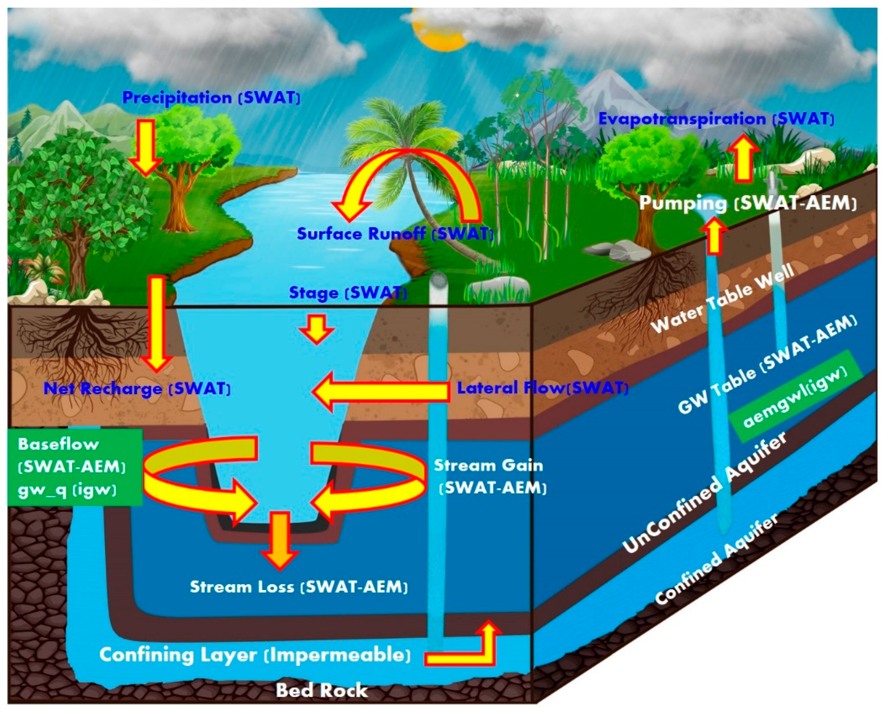
SWAT-AEM models are coupled together with suitable modifications in the SWAT FORTRAN code to call and execute the Bluebird AEM engine which allows for daily interactions between the SW-GW models. The coupled model can represent the stream flow and baseflow in channels along with stream-aquifer hydraulics, surface water diversions and groundwater pumping in terms of irrigation/other domestic water uses, and groundwater recharge in terms of percolation from the soil profile. The structure and process level integration between the SWAT-AEM model are illustrated in Figure 1 and Figure 2.
Figure 3 represents the different hydrologic variables exchanged between SWAT and AEM models. The integration of SWAT-AEM involves input creation (Pre-processor and Post-Processor) and process simulation. The pre-processing of SWAT input to AEM and post-processing of AEM output to SWAT is conducted through a call to Python scripting from within the SWAT FORTRAN code.
The integrated SWAT-AEM model initiates by running the SWAT model with the primary inputs (DEM, landuse, Soil, Slope, and Weather data). In SWAT, the watershed is divided into sub-watersheds, which are further subdivided into unique Hydrologic Response Units (HRUs). In the AEM GW model, SWAT SW features (HRU/reach/reservoir) are discretized into analytic elements as shown in Figure 4. SWAT simulated variables, such as recharge of the sub-basin/HRU, river/reservoir/pond characteristics, such as bed hydraulic conductivity, width, base elevation (with reference to DEM), depth, thickness, and water level are derived and formatted to analytic elements (point, area, or line elements) using the pre-processor python code to run the AEM GW model as shown in Figure 2.
The GW model could be called to run at every time step (daily) or at a user-specified time step (e.g., weekly, 10 daily, monthly, etc.) or after the accumulated recharge from SWAT reaches a user-specified threshold for a quasi-steady state simulation. Using the pre-processed output from SWAT, the AEM GW model is run. The outputs obtained from the AEM model are hydraulic head distribution across the domain and the baseflow contribution (either gaining stream or losing stream). These variables are then formatted using a postprocessor python code for feedback into SWAT. Thus, the interactions between the SW-GW are computed, and the critical variables are exchanged between SWAT and AEM, wherein the spatio-temporal characteristics in the watershed are properly reflected.

2.4. Conversion of SWAT SW Features to Analytic Elements

The linkage between the SWAT and AEM model is based on mapping schemes that pass the HRU/sub-basin-based variable recharge from the soil zone and reach/stream channel-based variable water level in the stream to analytic elements. (Figure 4). The analytic elements include the following: Area element (recharge from rainfall/irrigation, seepage from reservoirs), line element (seepage from streams with resistance specified rivers), point element (GW pumping) and boundary conditions (far field reference head). The boundaries of the sub-basins, stream channel network and reservoir shape files are simplified with a smaller number of vertices using GIS operation. Later, the vector shape files (.shp) are converted to Atlas Boundary files (.bna) format using the AEM GW model.
In the AEM model, the river is defined as resistant to specified river elements so that the system would be able to simulate both gaining stream and losing stream based on the simulated groundwater level in relation to the bed level of the stream. The water level based on the simulated stream flow rate and channel hydraulic characteristics (river bed conductivity, thickness, and elevation of the river bed) is obtained from the SWAT model and given to the river (line) analytic element. Once the analytic elements are created, the global aquifer parameters, such as aquifer base, thickness, specific storage, hydraulic conductivity, and porosity are created. Once the analytic elements have been parameterized appropriately, the far field boundary condition (reference head) is specified. The far-field conditions are designed to model the influence of faraway hydrogeological features (e.g., seawater level or water level from some observation well-connected to the aquifer where the level is relatively steady) upon the system.
If a stream segment contributes baseflow (indicated by positive extraction rate in AEM) during the time-step, then the reach is assumed to be a “gaining stream”. In such a case, no transmission loss is simulated by SWAT. However, if the baseflow contribution of the stream segment is zero (indicated by the negative extraction rate in AEM), then the reach is assumed as a “losing stream” and the transmission loss is simulated in SWAT. The well elements are used to represent pumping wells that are either adding (negative pumping rate) or removing (positive pumping rate) water from the aquifer. Once the AEM GW model is created, the model is run in a quasi-steady state with watershed-wide recharge and stream flow input from the SWAT and the AEM simulated hydraulic head at the watershed boundary is taken as the boundary condition for the next time step for the integrated SWAT-AEM model. This is further explained in the subsequent sections (Section 2.5).

2.5. Boundary Conditions for Quasi Steady-State Simulations

In the integration of SWAT and AEM, developing a quasi-steady-state framework is essential for simulating the time-varying impacts due to recharge and groundwater pumping on the groundwater levels. For the quasi-steady-state framework, the head values are extracted at each time step for the outer vertices of the basin boundary. Up to 10 internal grid points closest to each of the outer vertices are also created within the basin boundary as shown in Figure 5 for assessing the water level fluctuations to be carried forward to the subsequent time steps.
For the first time step, the model interpolated head from the observations at the outer vertices is used as the initial condition (H0, x). During the subsequent time steps, the water level fluctuation (ΔH) at the 10 closest internal grid points for each of the outer vertices is obtained by subtracting the initial head (HIO) by the current head (HIO+). The average water level fluctuation of the 10 internal grid points is then used to update the delta change in the boundary condition of each of the corresponding outer vertices for the subsequent time step: Ht + 1, x = Ht, x + difference in head (ΔH).
Thus, the quasi-steady state 2D-analytic element model was developed via media to address the limitations of a simple 1D representation of groundwater flow in SWAT. Such an approach also minimizes the complexity and computational effort involved in using a complete 3D model, such as MODFLOW.
The SWAT outputs, GW recharge and river stage are pre-processed and given as input to the AEM GW at a monthly time interval to simulate the quasi-steady state. The outputs obtained from the AEM model, such as GW height (hydraulic head distribution) and the baseflow contribution (either gaining stream or losing stream) are then post-processed for feedback into SWAT for updating the aquifer storage.
In SWAT, GW discharge is assumed to occur if the depth of a shallow aquifer increases above the user-defined threshold value. However, it will be difficult to compute the flow rate from the river to the aquifer if the depth of the shallow aquifer is lower than the threshold value. The major limitation of the SWAT model is to use river bed elevation and aquifer depth values for estimating baseflow gain or loss from the system. However, the AEM GW model can handle the river aquifer interaction by using the river bed elevation and aquifer depth by incorporating it as a resistance-specified river boundary condition. The user needs to specify the resistance, bottom elevation, and either the flux or the surface water elevation obtained from the SWAT model. The resistance is computed by using the local hydraulic conductivity of the aquifer, local saturated thickness and bottom resistance. To match the channel of SWAT with the river element in the AEM GW model, the river elevation is obtained from the DEM. The exchange rate in each element is computed by adding the contributed GW flow to the river and the contributed river flow to the aquifer for each channel of SWAT. The exchange rate between the river and the aquifer is converted at each element from the GW model and the baseflow is passed on to the respective channel in the SWAT model within the coupled SWAT-AEM model.
Thus, the integrated model distributes the available GW from SWAT with respect to spatial locations of sub-basins and the mass balance is achieved.

2.6. Model Application to the Study Region

Study Area Description

San Jacinto is one of the smallest river basins in Texas. It is located in the West Gulf coast section of the coastal province, which is predominantly a smooth, depositional plain rising from sea level to an altitude of 60.96 m. The total watershed area is 7251 sq. km encompassing 40–100% area covered which includes seven counties (Walker, Waller, Liberty, Montgomery, Grimes, San Jacinto and Harris) in Texas. The San Jacinto River originates from Lake Houston in Harris County and runs to the Gulf through Galveston Bay with a total length of 136 km. The San Jacinto River branches into two forks which are known as the East and West Forks. The West Fork of the San Jacinto river feeds Lake Conroe and flows southwards through Montgomery county to coincide with the East Fork in the northeast of Harris County to form Lake Houston. The East Fork begins from Walker county which flows south through Cleveland in Liberty County, Montgomery County and into the north end of Lake Houston. Later, both rivers merge in the south with Buffalo Bayou before the mouth of Galveston bay.
The climate is moist sub humid. The dominant land use type is evergreen forest and pasture. The average rainfall in this watershed is 1117.6–1168.4 mm. For rural watersheds, the average portion of rainfall becomes of stream flow is 279.4 mm (East Fork above Lake Houston, i.e., 7.93 m3/s) to 330.2 mm (Spring Creek at 1–45, i.e., 6.34 m3/s) [57].
There is only one major aquifer, the Gulf Coast Aquifer System, (GCAS) in this region. The local formation, such as Goliad Sand, Willias Sand and Lissie formation in the central third of the basin are the major source of Groundwater. About 30% of the state is covered by Gulf Coast and Carrizo Wilcox aquifers in the coastal plains which account for two-thirds of the groundwater in storage. Although more groundwater is pumped from the Ogallala Aquifer than all other aquifers combined, the total recoverable groundwater storage remaining in this aquifer amounts to between 95.3 and 286 million acre-feet, or about 5 % of the recoverable groundwater in storage in Texas [57]. The Gulf Coast aquifer discharges most groundwater to surface water. There are two major reservoirs in this Watershed, (i) Lake Conroe and (ii) Lake Houston.
Lake Conroe is located in the outcrop of GCAS, especially, in the Willias Sans and Oakville formations which have a moderate to high interaction between the aquifer and reservoir. Additionally, in Lake Houston, the formation is Beaumont Clay which is low permeable and interaction between the reservoir and aquifer would be minimal. Houston city lies in Harris County and is considered a populous city in the state of Texas. Tremendous water has been pumped from the ground for many years in Houston city, which in turn causes land subsidence and seawater intrusion into the aquifers. Meeting the water supply needs of the Houston metropolitan area is considered one of the major issues in the watershed which decreases the groundwater. In this study, only the upper SJRB, excluding the Lake Houston and Houston City area (7321 sq km), is modeled. The aquifer properties used for the SWAT-AEM model [58,59,60,61,62,63] are tabulated in Table 1.Observations from four wells are available for this watershed from the year 2007 to 2018 [61].

2.7. SWAT model for the San Jacinto River Basin (SJRB)

2.7.1. Model Construction

A SWAT model was set up for SJRB using ArcSWAT [54]. The SWAT model requires input, such as topography, land use and management, soil, weather, and stream channels. The National Elevation Dataset (NED) from the U.S. Geological Survey is at a 90 m resolution with burned-in hydrography from high-resolution NHDPlus data [64]. Land use data are obtained from the US Department of Agriculture’s Cropland Data Layer (CDL), an annual satellite imagery-derived land cover map for the year 2009 and divided into 24 land use classes [65]. Soil data used are the STATSGO Soil database mapped at the scale of 1:250,000 [66]. These data are used to obtain topography, soil and Landuse types, respectively. Figure 6 shows the locations of weather stations, stream flow gauge stations and observation wells. For this testing phase, the watershed is delineated into the coarser levels of the sub-basins. The drainage basin is divided into 27 sub-basins and the area of each sub-basin ranges from 5.86 to 1183.807 km2, while the length of the channel of each sub-basin ranges from 4.67 to 57.67 km. In this study region, there are about seven gauging locations obtained from USGS [67] for observed stream flow (in m3/s) available from the year 2000 to 2017.
Groundwater information from the Texas Water Development Board (TWDB) and aquifer properties are clipped from the Groundwater Availability Model (GAM) developed for the Northern portion of the Gulf Coast Aquifer system [61]. This input data are used to determine the aquifer characteristics (hydraulic conductivity, specific storage) for AEM GW model inputs.
However, due to the semi-distributed features of SWAT, the spatial locations of each HRU within sub-basins are not determined. To reflect the same, the spatially distributed recharges and the river stage (along with river bed conductivity, thickness, and hydraulic conductivity of river bed) obtained from the SWAT model are given as input to the SWAT-AEM model. Additionally, the aquifer properties, such as base, thickness, specific storage, hydraulic conductivity and porosity are fed as an input to the coupled model. At every time step of SWAT-AEM coupling (in this case monthly time interval), the boundary conditions are updated as described in Section 2.4 and according to Figure 5.

2.7.2. Model Calibration (SWATCUP)

The SWAT model is calibrated for stream flow at seven outlets by implementing the Sequential Uncertainty Fitting Algorithm (SUFI2) with the SWAT Calibration Uncertainty Procedure (SWATCUP) [68]. The SWATCUP version used is 5.2.1. Calibration was performed based on daily stream flow records from January 2000 to December 2017, with 3 years as a warmup period using a range of parameters, including Nash Sutcliffe Efficiency (NSE), Percentage of Bias (PBIAS), Kling-Gupta Efficiency (KGE) and Coefficient of Determination (R2) which allows the model to stabilize further simulations. Eleven parameters related to stream flow were selected and assigned initial calibration value ranges based on expert judgment and previous SWAT applications in different catchments [69,70].
The calibrated model parameters are given in Table 2. These calibration parameters were then used in the coupled SWAT-AEM model.

3. Results and Discussions

3.1. SW-GW Assessment in SWATAEM Model

The integrated model initiates by running the SWAT model with the primary inputs (DEM, Landuse/Soil/Slope, Weather data). The main computation of SWAT is conducted using the ‘simulate’ subroutine. The SWAT model is run through the daily loop with sub-basin calculations performed for each day and the output variables recharge of the sub-basin/ HRU extracted for the AEM model. Further, reservoir/pond characteristics, such as conductance, elevation, depth, base, thickness, height fraction and the river characteristics, such as thickness, width, conductivity and water depth derived from the SWAT are formatted to analytic elements (Point, area or Line elements) in pre-processor Python code to run the AEM based GW model as shown in Figure 4. After the inputs are formatted, the AEM GW model is run and the outputs obtained are sub-basin/HRU-based recharge, base flow, and gaining stream or losing stream. These are then formatted using postprocessor Python code. This integration procedure is repeated on a monthly timescale until the simulation reaches the end of the loop. Since the GW model is a steady-state model, to make a realistic estimate of groundwater simulation in a quasi-steady state, the boundary conditions are continuously updated between each simulation as stated in Section 2.5. The outputs obtained from the SWAT-AEM model are stream flow, GW level fluctuations, the spatial distribution of the GW head, the SW-GW interaction stream reaches and the overall water balance in the study region. The results are elaborated in detail as follows:

3.1.1. Stream Flow

In order to evaluate the performance of the calibrated SWAT model against the coupled SWAT-AEM model, daily stream flows were simulated using the SWAT and SWAT-AEM models at the seven USGS stream flow gauge locations (USGS 08068090, USGS 08070200, USGS 08068450, USGS 08071000, USGS 08070500, USGS 08068500, USGS 08069000) during the 2000–2017 study period. The performance statistics (such as NSE/R2/PBIAS) are tabulated in Table 3 to testify to the model’s efficiency for both daily and monthly time steps. It is to be noted that the SWAT-AEM integrated model was not calibrated. Only the standalone SWAT model was calibrated, and the calibrated parameters are used in the SWAT-AEM model. By incorporating this, the model seems to considerably improve the accuracy of stream flow.
Figure 7 shows the time series plot of monthly observed and simulated stream flow for the stream flow gauge locations. The NSE values for monthly discharge rates are found to be acceptable (≥0.5) [71]. As per recommendation [71,72,73], for the performance statistics, one can conclude from the SWAT-AEM results that the gauge locations “USGS 08070500 and USGS 08070200” are categorized as “very good” and “USGS 08071000, USGS 08068090 and USGS 08068450” as “Good ”. The results of “USGS 08068500 and USGS 08069000” are found to be “satisfactory”. PBIAS ranged from +8 to +20 during the calibration period, which suggests good model performance in most of the stations. In each of the gauging stations, the coupled SWAT-AEM model performed better than the standalone SWAT model. This coupled SWAT-AEM model will be beneficial in situations where the influence of surface and groundwater interactions may be dominant.
Further, the simulation differences to the baseflow are examined using the baseflow separation tool, BFLOW [74,75] to evaluate the fraction of baseflow from stream flow. A summary of these results is shown below in Table 4. In all seven gauges, the coupled model resulted in a lower baseflow fraction of stream flow than the Standalone SWAT model and closely matched the observed values. The baseflow in most of the gauges, SWAT and SWAT-AEM had a percent difference of +(9–20)% from the observed value.
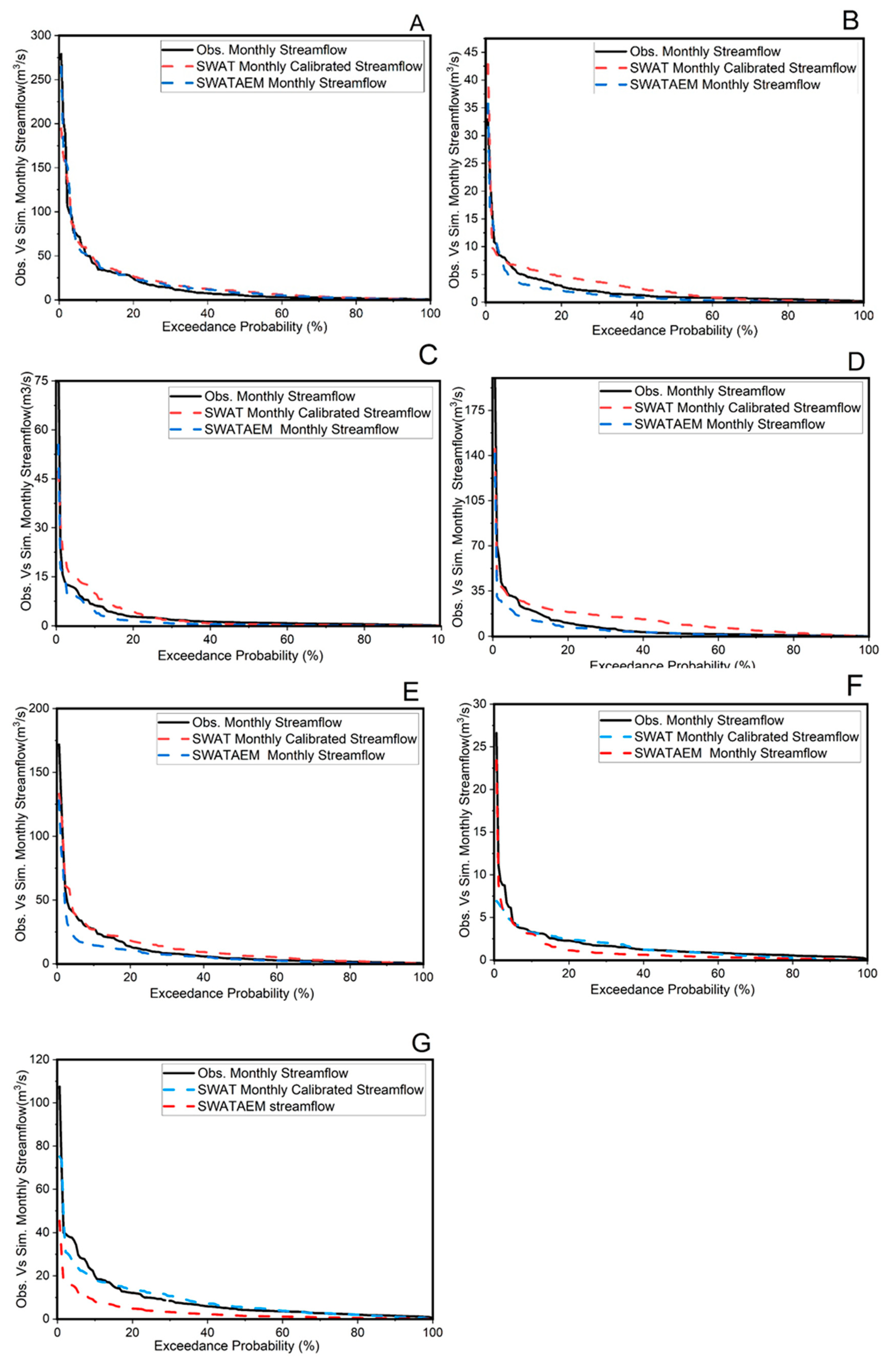
It is evident from Table 4 that the SWAT-AEM model results are close to the observed values in most of the gauges because the GW flow and the resulting baseflow are reasonably accounted for in the integration, which was lacking in the standalone SWAT model. For additional comparison between calibrated standalone SWAT and SWAT-AEM models, flow duration curves (Figure 8) are also plotted for observed and simulation stream flows at the gauge locations. Figure 8A–G shows that the calibrated standalone SWAT model underestimated high flows in almost all of the gauges.
Flow duration curve results from the coupled SWAT-AEM model show a better prediction of stream flow compared to the calibrated SWAT model itself, particularly for low flows (below 70 percentile) for all the gauge locations. The water yield in the SWAT-AEM is mostly dominated by lateral flow and GW return flow. The GW contribution to all the sub-basins has a high contribution to water yield. This improvement is because of the 2D interaction simulated among the aquifers across the different sub-basins and the individual sub-basin with the river in the SWAT-AEM framework.

3.1.2. Ground Water (GW) Levels

By Visual inspection of graphs (Figure 9A–D), the simulated GW levels from the SWAT-AEM model are able to follow the pattern of GW level fluctuations. However, there is high variability in the simulated results for the observation wells (ranging from a 3 to 10 m difference from observed data). This could be due to the difference between the actual pumping rate and the constant pumping rate assumed from the available literature. Nevertheless, the coupled model is able to capture the pattern of GW fluctuation.
Compared with SWAT, the SWAT-AEM model not only produced outputs for stream flow but GW head for each of the observation stations. Figure 10 shows that the spatial distribution of GW heads in the coupled SWAT-AEM model is able to capture the spatial distribution of simulated GW levels in some regions of the basin. However, due to less number and distribution of GW observations, only the simulated spatial representation of the GW head is shown in Figure 10. In general, it was found that there is a significant difference between observed and simulated values in some regions of the basin as shown in Figure 9. This is due to the uncertainties associated with the assumed and actual spatial variability of the aquifer properties and the difference between actual and assumed pumping rates. Further, the aquifer is modeled as a single layer for the entire thickness of the aquifer, and therefore, it ignores the vertical heterogeneity in the aquifer and its associated aquifer properties.

3.1.3. Ground Water Discharge Rates

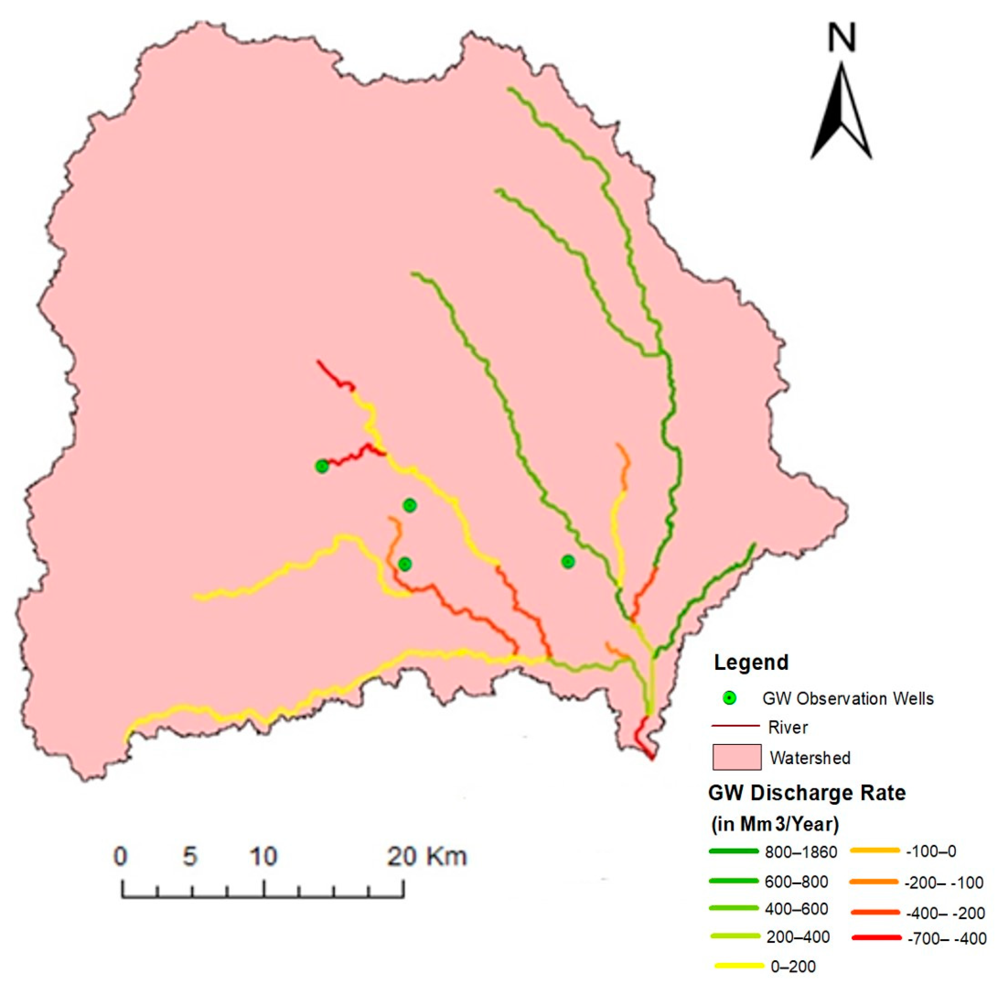
The simulated GW recharge ranges from less than 8 mm/month to greater than 160 mm/month which reflects the diversified climate conditions, soil types, and depths. In this region, the major runoff is discharged to the Gulf of Mexico and shallow aquifers which contribute to baseflow. In this watershed, the precipitation is concentrated from June to November and recharge also shows the same trend. The simulated GW discharge rates were plotted for specific stream reaches where there may be considerable SW-GW interaction. Available information from the observed stream networks and groundwater indicates there is an interaction between the stream and the aquifer in the southeast part of the SJRB [57]. This comparison will be very suitable for us to quantify the spatio-temporal changes in SW-GW interaction processes. Figure 11 shows the average annual spatio-temporal distribution of the stream aquifer interaction which is one of the deliverables which can be obtained from this integrated SWAT-AEM model.
The majority of the SW-GW interaction is the discharge from the aquifer to the streams (gaining stream). The highest stream–aquifer interaction occurs during July–August. However, there is high spatial and temporal variability in the magnitude and direction (gaining/losing) of the stream aquifer interaction. The simulated SW-GW exchange flux values from the SWAT-AEM model varied spatially, but the values were primarily positive which indicates discharge from the aquifers. Positive values include the annual average GW discharge rate of 1853 Million cubic meters (Mm3/year), whereas the negative values include the annual average GW seepage rate of 679 Million cubic meters (Mm3/Year). This indicates that in this watershed, there is significant SW-GW interaction and which further proves that this model will be useful for providing dynamic data for future SW-GW projections. The simulated segments of losing and gaining streams match the documented field studies which were reported in the Texas Aquifer Report [57]. This output helps in understanding the interaction between SW-GW components and mapping the spatiotemporal distribution of the watershed, which is needed for efficient water resource management. The interaction mainly depends on the riverbed conductance, precipitation and hydraulic conductivity of the aquifer.

3.1.4. Overall Water Balance

As compared to the SWAT model, the SWAT-AEM model not only improved stream flow but also the baseflow and GW levels. The coupled model showed a satisfactory agreement between the GW level and dynamics simulated by the coupled SWAT-AEM model, which is plotted for the four of the observation wells as shown in Figure 9 and Figure 10. Based on the SWAT-AEM model result, a considerable percentage (65%) of precipitation (1259.2 mm/year) is evaporated (818.48 mm/year). The remaining water contributes to (24%) of surface runoff (302.208 mm/year) which further matches the observed average annual values (26% and 64%) from the GW system from the available literature [63]. The simulated baseflow contribution to the stream flow is 27% (69.50 mm/year) and 23% which matches the range of the US baseflow map.Table 5 shows the comparison of average annual result summary of water balance components for San Jacinto River basin during the study period for SWAT and SWAT-AEM models.
Thus, the improvement in this coupled model is to reassert the preference to use SWAT-AEM in the regions where there is significant SW-GW interaction. The coupled SWAT-AEM model is tested for the San Jacinto river basin in Texas wherein the spatio-temporal patterns of the SW-GW interaction are determined for the study region.

4. Conclusions

In this paper, a comprehensive hydrologic modeling framework for the coupled SWAT-AEM model was conceptualized, developed and demonstrated in the San Jacinto basin, Texas. This is the first time a study has attempted to see how the Analytic Element based GW modeling method will improve the model results within a coupled SW-GW modeling framework. The input/output exchange processes of the SWAT and AEM models are programmed in Python and FORTRAN environments.
The SWAT-AEM model was run for the 2000–2017 period and tested against stream flow discharges and GW levels at seven stream flow gauge stations and four monitoring GW observation stations. The coupled model was applied to assess the hydrology of the SJRB in Texas with significant SW-GW interaction. Preliminary results show that the coupled model is able to better capture the stream flow and GW levels satisfactorily compared to the Standalone SWAT model as shown in Table 3 and Table 4.
By this coupled model architecture, the water balance components in the hydrological cycle are improved. Further improvement can be conducted by adjusting the soil and aquifer hydraulic conductivity. Additionally, simultaneous calibration and validation in the study region need to be studied to improve the coupled SWAT-AEM model for the prediction of stream flow and GW level fluctuations. The SWAT-AEM model better captured the low flows, which was a major limitation of the Standalone SWAT model (i.e., underpredicts the low flows). Overall, the coupled model shows a promising direction for implementation in the studies with a simple single-layer aquifer configuration but has significant SW-GW interaction processes.
The major limitation in the SWAT-AEM model integration is that the model is primarily a two-dimensional pseudo steady state, single layer aquifer model and the aquifer properties are piecewise constant aquifer (i.e., the model cannot handle continuously varying hydraulic conductivity, porosity, or base). Regarding the study area datasets, we had data limitations in terms of observation wells and information regarding the real pumping rates for the selected year. Future works could focus on when (under what conditions) a simpler SWAT-AEM coupling is sufficient for much more complex integration with MODFLOW or other numerical groundwater models.

Author Contributions

Conceptualization, K.S. and B.N.; methodology, K.S. Investigation, Data Collation and Preparation, K.S. and R.S.; Model Development, K.S. and B.N.; SWAT model setup, calibration, K.S. Result Analysis and Visualization: K.S. and B.N.; writing—original draft preparation, K.S.; writing—review and editing, B.N. and R.S.; supervision, B.N. All authors have read and agreed to the published version of the manuscript.

Funding

This research received no external funding.

Acknowledgments

We would like to acknowledge and thank the scholarship provided by the Ministry of Human Resource Development (MHRD), Government of India. We thank the two anonymous reviewers and editors for insightful suggestions and encouraging comments, which improved the quality of the manuscript.

Conflicts of Interest

The authors declare no conflict of interest.

References

  1. Knapp, K.C.; Weinberg, M.; Howitt, R.; Posnikoff, J.F. Water transfers, agriculture, and ground water management: A dynamic economic analysis. J. Environ. Manag. 2003, 67, 291–301. [Google Scholar] [CrossRef]
  2. de Roo, A.; Bisselink, B.; Beck, H.; Bernhard, J.; Burek, P.; Reynaud, A.; Pastori, M.; Lavalle, C.; Jacobs, C.; Baranzelli, C.; et al. Modelling Water Demand and Availability Scenarios for Current and Future Landuse and Climate in the Sava River Basin; Publications Office of the European Union: Luxembourg, 2016; EUR 27701 EN. [Google Scholar]
  3. El-Kadi, A.I. Watershed models and their applicability to conjunctive use management. Water Resour. Bull. 1989, 25, 125–137. [Google Scholar] [CrossRef]
  4. Werner, M.; Reggiani, P.; de Roo, A.; Bates, P.; Sprokkereef, E. Flood forecasting and warning at the river basin and at the European scale. Nat. Hazards 2005, 36, 25–42. [Google Scholar] [CrossRef]
  5. de Graaf, I.E.M.; Sutanudjaja, E.H.; van Beek, L.P.H.; Bierkens, M.F.P. A high-resolution global-scale groundwater model. Hydrol. Earth Syst. Sci. 2015, 19, 823–837. [Google Scholar] [CrossRef]
  6. De Lange, W.J. A Groundwater Model of The Netherlands; Tech. Rep.90.066; National Institute for Inland Water Management and Waste Water Treatment: Lelystad, The Netherlands, 1991. [Google Scholar]
  7. Sutanudjaja, E.H.; van Beek, L.P.H.; de Jong, S.M.; van Geer, F.C.; Bierkens, M.F.P. Calibrating a large-extent high-resolution coupled groundwater-land surface model using soil moisture and discharge data. Water Resour. Res. 2013, 50, 687–705. [Google Scholar] [CrossRef]
  8. Sophocleous, M. Interactions between Groundwater and Surface Water: The state of the science. Hydrogeol. J. 2002, 10, 52–67. [Google Scholar] [CrossRef]
  9. Niraula, R.; Norman, L.M.; Meixner, T.; Callegary, J.B. Multi-gauge Calibration for modeling the Semi-Arid Santa Cruz Watershed in Arizona-Mexico Border Area Using SWAT. Air Soil Water Res. 2012, 5, 41–57. [Google Scholar] [CrossRef]
  10. Xie, X.; Cui, Y. Development and test of SWAT for modelling hydrological processes in irrigation districts with paddy rice. J. Hydrol. 2011, 396, 61–71. [Google Scholar] [CrossRef]
  11. Azimi, M.; Heshmati, G.A.; Farahpour, M.; Faramarzi, M.; Abbaspour, K.C. Modeling the impact of rangeland management on forage production of sagebrush species in arid and semi-arid regions of Iran. Ecol. Model. 2013, 250, 1–44. [Google Scholar] [CrossRef]
  12. Ye, L.; Grimm, N.B. Modelling potential impacts of climate change on water and nitrate export from a mid-sized, semiarid watershed in the US Southwest. Clim. Change 2013, 120, 419–431. [Google Scholar] [CrossRef]
  13. Raneesh, K.Y.; Santosh, G.T. A study on the impact of climate change on stream flow at the watershed scale in the humid tropics. Hydrol. Sci. J. 2011, 56, 946–965. [Google Scholar] [CrossRef]
  14. Chemingui, A.; Horriche, F. Implementation of a Hydrological Model of Groundwater Recharge for the Chiba Catchment (Cap-Bon, Tunisia); Centre Eau Terre Environment: Quebec City, QC, Canada, 2013. [Google Scholar]
  15. Mitchell-Bruker, S.; Haitjema, H.M. Modelling steady state conjunctive GW and SW flow with analytic elements. Water Resour. Res. 1996, 32, 2725–2732. [Google Scholar] [CrossRef]
  16. Jin, X.; Sridhar, V. An Integrated Model Coupling VIC and MODFLOW to Study the Hydrological Prediction at the Snake River Basin; EPSCOR Publications: Albuquerque, NM, USA, 2010. [Google Scholar]
  17. Arnold, J.G.; Allen, P.M.; Bernhardt, G. A comprehensive surface—GW flow model. J. Hydrol. 1993, 142, 47–69. [Google Scholar] [CrossRef]
  18. Liu, W.; An, W.; Jeppesen, E.; Ma, J.; Yang, M.; Trolle, D. Modelling the fate and transport of Cryptosporidium, a zoonotic and waterborne pathogen, in the Daning River watershed of the Three Gorges Reservoir Region, China. J. Environ. Manag. 2019, 232, 462–474. [Google Scholar] [CrossRef] [PubMed]
  19. Markstrom, S.L.; Niswonger, R.G.; Regan, R.S.; Prudic, D.E.; Barlow, P.M. GSFLOW—Coupled Ground-Water and Surface-Water Flow Model Based on the Integration of the Precipitation-Runoff Modeling System (PRMS) and the Modular Ground-Water Flow Model (MODFLOW-2005). In U.S. Geological Survey Techniques and Methods 6-D1; Geological Survey: Reston, VA, USA, 2008; p. 254. [Google Scholar]
  20. Sophocleous, M.; Perkins, S.P. Methodology and application of combined watershed and ground-water models in Kansas. J. Hydrol. 2000, 236, 185–201. [Google Scholar] [CrossRef]
  21. Arnold, J.G.; Kiniry, J.R.; Srinivasan, R.; Williams, J.R.; Haney, E.B.; Neitsch, S.L. Input/Output Documentation, Chapter1; Texas Water Resources Institute: College Station, TX, USA, 2012. [Google Scholar]
  22. Arnold, J.G.; Kiniry, J.R.; Srinivasan, R.; Williams, J.R.; Haney, E.B.; Neitsch, S.L. SWAT 2012 Input/Output Documentation; Texas Water Resources Institute: College Station, TX, USA, 2013. [Google Scholar]
  23. Refsgaard, J.C.; Storm, B. MIKE SHE. In Computer Models of Watershed Hydrology; Singh, V.P., Ed.; Water Resources Publications: Littleton, CO, USA, 1995; pp. 809–846. [Google Scholar]
  24. Tian, Y.; Zheng, Y.; Wu, B.; Wu, X.; Liu, J.; Zheng, C. Modeling surface water-groundwater interaction in arid and semi-arid regions with intensive agriculture. Environ. Model. Softw. 2015, 63, 170–184. [Google Scholar] [CrossRef]
  25. Sudicky, E.A.; Jones, J.P.; Park, Y.J.; Brookfield, A.E.; Colautti, D. Simulating complex flow and transport dynamics in an integrated surface-subsurface modeling framework. Geosci. J. 2008, 12, 107–122. [Google Scholar] [CrossRef]
  26. Gayathri, K.D.; Ganasri, B.P.; Dwarakish, G.S. A review on hydrological models. In Proceedings of the ICWRCOE Conference, Karnataka, India, 12–14 December 2015; Aquatic Procedia 4. pp. 1001–1007. [Google Scholar]
  27. Behera, S.; Panda, R.K. Evaluation of management alternatives for an agricultural watershed in a sub-humid subtropical region using a physical process based model. Agric. Ecosyst. Environ. 2006, 113, 62–72. [Google Scholar] [CrossRef]
  28. Swain, E.D.; Wexler, E.J. A Coupled Surface-Water and Ground-Water Flow Model (MODBRANCH) for Simulation of Stream–Aquifer Interaction: U.S. Geological Survey Techniques of Water-Resources Investigations; Book 6, Chapter A6; U.S. Geological Survey, Information Services: Reston, VA, USA, 1996; p. 125. [Google Scholar]
  29. Sophocleous, M.A.; Koelliker, J.K.; Govindaraju, R.S.; Birdie, T.; Ramireddygari, S.R.; Perkins, S.P. Integrated numerical modelling for basin-wide water management: The case of the Rattlesnake Creekbasin in south-central Kansas. J. Hydrol. 1999, 214, 179–196. [Google Scholar] [CrossRef]
  30. Panday, S.; Huyakorn, P.S. A fully coupled physically-based spatially-distributed model for evaluating surface/subsurface flow. Adv. Water Resour. 2004, 27, 361–382. [Google Scholar] [CrossRef]
  31. Guzha, A.C. Modeling the interaction of surface and sub SW flow by linking TOPMODEL and MODFLOW. Int. J. Water 2013, 7, 191–205. [Google Scholar] [CrossRef]
  32. Aliyari, F.; Bailey, R.T.; Tasdighi, A.; Dozier, A.; Arabi, M.; Zeiler, K. Coupled SWAT MODFLOW model for large-scale mixed agro urban river basins. Environ. Model. Softw. 2019, 115, 200–210. [Google Scholar] [CrossRef]
  33. Guzman, J.A.; Moriasi, D.N.; Gowda, P.H.; Steiner, J.L.; Starks, P.J.; Arnold, J.G.; Srinivasan, R. A model integration framework for linking SWAT and MODFLOW. J. Environ. Model. Softw. 2015, 73, 103–116. [Google Scholar] [CrossRef]
  34. ASCE Task Committee. Criteria for evaluation of watershed models. J. Irrigat. Drain. Eng. 1993, 119, 429–442. [Google Scholar] [CrossRef]
  35. Abbas, S.; Xuan, Y.; Bailey, R. Improving River Flow Simulation Usinga Coupled Surface-Groundwater Model for Integrated Water Resources Management. EPiC Ser. Eng. 2018, 3, 1–9. [Google Scholar]
  36. Bailey, R.T.; Wible, T.C.; Arabi, M.; Records, R.M.; Ditty, J. Assessing Regional-Scale Spatio-Temporal Patterns of Groundwater-Surface Water Interactions Using a Coupled SWAT-MODFLOW Model. Hydrol. Processes 2016, 30, 4420–4433. [Google Scholar] [CrossRef]
  37. Gao, F.; Feng, G.; Han, M.; Dash, P.; Jenkins, J.; Liu, C. Assessment of Surface Water Resources in the Big Sunflower River Watershed using Coupled SWAT-MODFLOW Model. Water 2019, 11, 528. [Google Scholar] [CrossRef]
  38. Kim, N.W.; Chung, I.M.; Won, Y.S.; Arnold, J.G. Development and application of the integrated SWAT-MODFLOW model. J. Hydrol. 2008, 356, 1–16. [Google Scholar] [CrossRef]
  39. Rathjens, H.; Beiger, K.; Bailey, R. SWATMOD-Prep: Interface for Preparing SWATMODFLOW Simulations, User Manual; Colorado State University: Fort Collins, CO, USA, 2016. [Google Scholar]
  40. Gassman, P.W.; Reyes, M.R.; Green, C.H.; Arnold, J.G. The soil and water assessment tool: Historical development applications, and future Research directions. Trans. ASABE 2007, 50, 1211–1250. [Google Scholar] [CrossRef]
  41. Guzman, J.A.; Moriasi, D.N.; Gowda, P.H.; Steiner, J.L.; Arnold, J.G.; Srinivasan, R. An integrated hydrologic modelling framework for coupling SWAT with MODFLOW. In Proceedings of the International SWAT Conference & Workshop 2012, New Delphi, India, 16–17 July 2012. [Google Scholar]
  42. Strack, O.D.L. Groundwater Mechanics; Prentice-Hall: Englewood Cliffs, NJ, USA, 1989. [Google Scholar]
  43. Haitjema, H.M. Analytic Element Modeling of Groundwater Low; Academic Press: San Diego, CA, USA, 1995. [Google Scholar]
  44. Haitjema, H.M. Modeling regional ground-water flow in Fulton County, Indiana: Using the analytic element method. Groundwater 1992, 30, 660–666. [Google Scholar] [CrossRef]
  45. Strack, O.D.L.; Haitjema, H.M.; Melnyk, J. Interactive modelling of the aquifers near the Tennessee-Tombigbee Waterway. In Symposium on Water and Related Land Resource Systems; Ohio.International.Federal.Automation.Control: Cleveland, OH, USA, 1980. [Google Scholar]
  46. Kelson, V.A.; Hunt, R.J.; Haitjema, H.M. Improving a regional model using reduced complexity and parameter estimation. Ground Water 2002, 40, 132–143. [Google Scholar] [CrossRef]
  47. WHAEM. Available online: https://www.epa.gov/ceam/wellhead-analytic-element-model-whaem (accessed on 3 July 2016).
  48. VisualAEM. Available online: https://www.civil.uwaterloo.ca/jrcraig/visualaem/main.html (accessed on 15 March 2014).
  49. James, R.; Matott, C.L.S. Visual AEM v1.0 Users Manual. Available online: https://www.civil.uwaterloo.ca/jrcraig/visualaem/main.html (accessed on 15 March 2014).
  50. Fitts, R.; Joshua, G.; Kathaleen, F.; Charles, M.; Seth, M. Analytic Element Modeling of Steady Interface Flow in multilayer aquifers using AnAqsim. Ground Water 2010, 53, 432–439. [Google Scholar] [CrossRef]
  51. Bakker, M.; Anderson, E.I.; Olsthoorn, N.; Strack, O.D.L. Regional GW modeling of the Yucca Mountain Site using analytic elements. J. Hydrol. 1999, 226, 167–178. [Google Scholar] [CrossRef]
  52. Bakker, M.; Strack, O.D.L. Analytic Elements for Multiaquifer Flow. J. Hydrol. 2003, 271, 119–129. [Google Scholar] [CrossRef]
  53. Hunt, R.J. GW modelling applications using the analytic element method. Groundwater 2006, 44, 5–15. [Google Scholar] [CrossRef]
  54. Soil and Water Assessment Tool, 2015. ArcSWAT Ver. 2012.10_1.18. Available online: http://swat.tamu.edu/software/arcswat/ (accessed on 9 September 2015).
  55. Hooghoudt, S.B. Bijdrage tot de kennis van enige natuurkundige grootheden van de grond. Versl. Landbouwkd. Onderz. 1940, 46, 515–707. [Google Scholar]
  56. Smedema, L.K.; Rycroft, D.W. Land Drainage—Planning and Design of Agricultural Drainage Systems; Cornell University Press: Ithica, NY, USA, 1983. [Google Scholar]
  57. Texas Natural Resource Consevation Commission; Parsons Engineering Science. Report on Surface Water/Groundwater Interaction Evaluation for 22 Texas River Basins; INC: New York, NY, USA, 1999. [Google Scholar]
  58. TWDB (Texas Water Development Board). Available online: https://s3.amazonaws.com/gw-models/USGS.HAGM.Archive.20131111.Version1.1.zip (accessed on 3 October 2018).
  59. TWDB (Texas Water Development Board). Available online: https://www3.twdb.texas.gov/apps/reports/WU/SumFinal_CountyPumpage (accessed on 10 July 2018).
  60. TWDB (Texas Water Development Board). Available online: http://www.twdb.texas.gov/groundwater/data/gwdbrpt.asp (accessed on 15 October 2018).
  61. TWDB (Texas Water Development Board). Available online: https://www.waterdatafortexas.org/groundwater (accessed on 15 October 2018).
  62. TWDB (Texas Water Development Board). Available online: https://www3.twdb.texas.gov/apps/reports/WU/SumFinal_CountyReport (accessed on 10 July 2018).
  63. TWDB (Texas Water Development Board). Available online: https://www.twdb.texas.gov/publications/reports/numbered_reports/doc/R380_AquifersofTexas.pdf (accessed on 16 July 2015).
  64. U.S. Geological Survey. 1993. Available online: https://apps.nationalmap.gov/downloader/#productSearch (accessed on 20 July 2018).
  65. Natural Resources Conservation Service, and United States Department of Agriculture.USADA-Cropland Data Layer(CDL). Available online: https://datagateway.nrcs.usda.gov/GDGOrder.aspx (accessed on 3 March 2016).
  66. Natural Resources Conservation Service, and United States Department of Agriculture. U.S. Generic Soil Map (STATSGO2). Available online: https://sdmdataaccess.sc.egov.usda.gov/ (accessed on 3 March 2016).
  67. U.S. Geological Survey, Texas Daily Streamflow Current Conditions. Available online: https://waterdata.usgs.gov/tx/nwis/current/?type=flow (accessed on 10 July 2018).
  68. Abbaspour, K.C. SWAT-CUP-2012: SWAT Calibration and Uncertainty Programs—A User Manual; Swiss Federal Institute of Aquatic Science and Technology: Dubendorf, Switzerland, 2012. [Google Scholar]
  69. Kollet, S.; Sulis, M.; Maxwell, R.M.; Paniconi, C.; Putti, M.; Bertoldi, G.; Coon, E.T.; Cordano, E.; Endrizzi, S.; Kikinzon, E. The integrated hydrologic model intercomparison project: A second set of benchmark results to diagnose integrated hydrology and feedbacks. Water Resour. Res. 2016, 53, 867–890. [Google Scholar] [CrossRef]
  70. Mishra, A.; Kar, S. Modelling hydrologic processes and NPS pollution in a small watershed in sub humid subtropics using SWAT. J. Hydrol. Eng. 2012, 17, 445–454. [Google Scholar] [CrossRef]
  71. Moriasi, D.N.; Arnold, J.G.; Van Liew, M.W.; Bingner, R.L.; Harmel, R.D.; Veith, T.L. Model evaluation guidelines for systematic quantification of accuracy in watershed simulations. J. Am. Soc. Agri. Biol. Eng. 2007, 50, 885–900. [Google Scholar]
  72. Molina-Navarro, E.; Andersen, H.E.; Nielsen, A.; Thodsen, H.; Trolle, D. The impact of the objective function in multi-site and multi-variable calibration of the SWAT model. Environ. Model. Softw. 2017, 93, 255–267. [Google Scholar] [CrossRef]
  73. Molina-Navarro, E.; Bailey, R.T.; Andersen, H.E.; Thodsen, H.; Nielsen, A.; Park, S.; Jensen, J.S.; Jensen, J.B.; Trolle, D. Comparison of abstraction scenarios simulated by SWAT and SWAT-MODFLOW. Hydrol. Sci. J. 2019, 64, 434–454. [Google Scholar] [CrossRef]
  74. Arnold, J.G.; Allen, P.M.; Muttiah, R.; Bernhardt, G. Automated baseflow separation and recession analysis techniques. Ground Water 1995, 33, 1010–1018. [Google Scholar] [CrossRef]
  75. Arnold, J.G.; Allen, P.M. Automated methods for estimating baseflow and ground water recharge from streamflow records. J. Am. Water Resour. Assoc. 1999, 35, 411–424. [Google Scholar] [CrossRef]
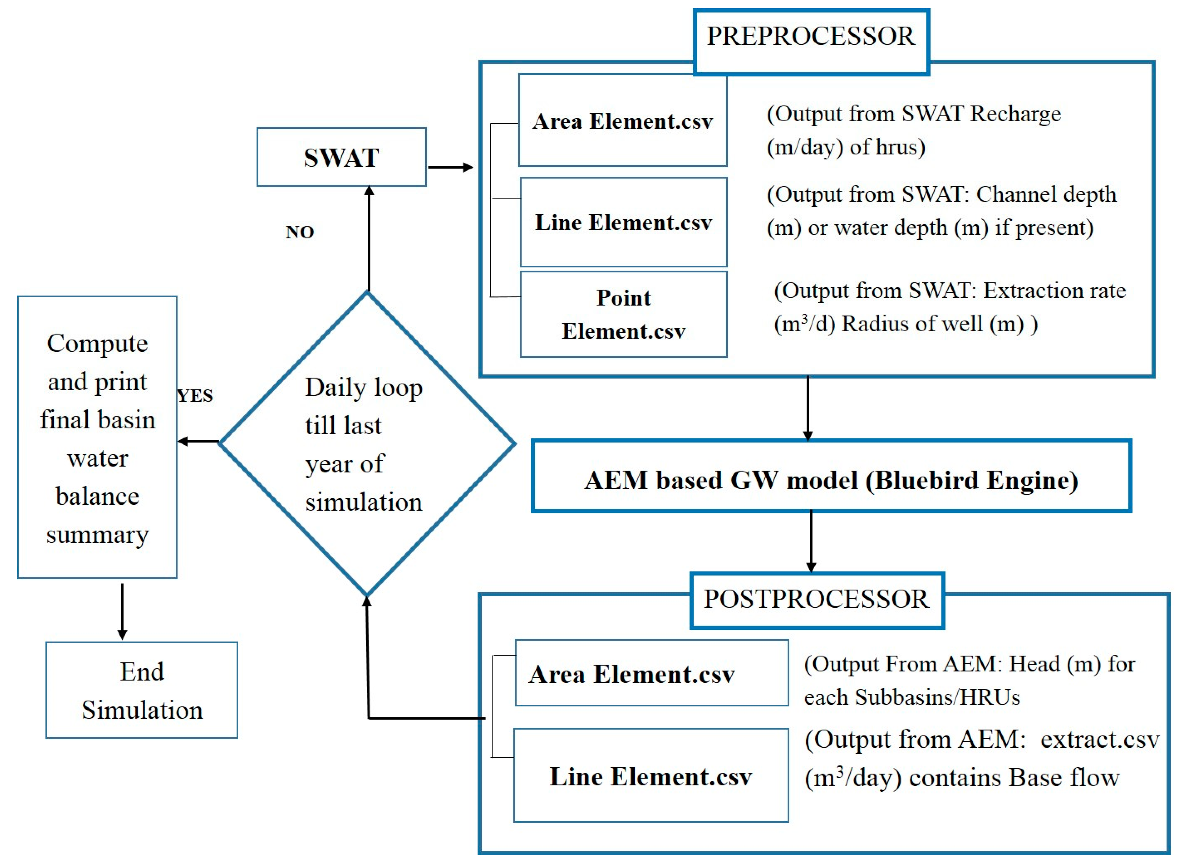
Figure 1. Flow chart explaining the components involved in the integrated SWAT-AEM.
Water 14 02753 g001
Figure 2. Methodology of integrated SWAT-AEM Model computation.
Water 14 02753 g002
Figure 3. Schematic diagram representing the interaction of integrated Surface and ground water model.
Water 14 02753 g003
Figure 4. Conversion of HRU/Subbasin to Analytic Elements.
Water 14 02753 g004
Figure 5. Boundary Condition in SWAT-AEM model.
Water 14 02753 g005
Figure 6. Location of study area (a) Inset map showing the location of San Jacinto River Basin in Unites States; (b) Inset map showing the location of San Jacinto River Basin in Texas; (c) Map of the study area showing the elevation, observation wells, stream flow gauging stations and weather stations.
Water 14 02753 g006
Figure 7. Flow Hydrograph for Observed and Simulated SWAT/SWATAEM stream flow (m3/s) for Seven gauge locations (A). USGS 08068090; (B). USGS 08070500; (C). USGS 08071000; (D). USGS 08070200; (E). USGS 08068500; (F). USGS 08068450.
Water 14 02753 g007
Figure 8. Flow Duration Curve for Observed and Simulated SWAT/SWATAEM stream flow (m3/s) for Seven gauge locations (A). USGS 08068090, (B). USGS 08070500, (C). USGS 08071000, (D). USGS 08070200, (E). USGS 08068500, (F). USGS 08068450 and (G). USGS 08069000.
Water 14 02753 g008
Figure 9. Time series plot showing the comparison of monthly observed Vs simulated water level (meter below land surface). (A). Observation Well 6044805; (B). Observation Well 6053516; (C). Observation Well 6055710 and (D). Observation Well 6053518.
Water 14 02753 g009
Figure 10. Simulated Spatial Distribution of GW head (w.r.t MSL, in m) by SWATAEM.
Water 14 02753 g010
Figure 11. Simulated average annual groundwater discharge (Mm3/year) from the aquifer to the stream network for selected study period, (2000–2017). The streams which are highlighted in green indicate GW discharge from the aquifer to the streams and the streams which are highlighted in red indicate the seepage from the stream to the aquifer as shown in Figure 11.
Water 14 02753 g011
Table 1. Range of Values used for Aquifer Properties from observations.
SI.NOAquifer PropertiesRange of Values
1Aquifer Conductivity (k)2 × 10⁻⁵ to 6 m/day
2Specific storage (Ss)1.819 × 10⁻⁵ to 0.20
3Aquifer Thickness (H)0.305 to 659.892 m
4Base Elevation −595.399 to 137.902 m
Table 2. Calibrated Model Parameters from SWATCUP.
ParametersUSGS Stream Flow Gauge Locations
08068090080705000807100008070200080684500806850008069000
r*_CN2 −0.0747−0.1691−0.1467−0.168−0.1857−0.0790−0.1493
r*_SOLAWC−0.0522−0.20830.40030.4810.44180.22780.3543
r*_SOL_K−0.39120.4248−0.4733−0.1330.00230.14630.2003
v*_SURLAG2.80225.14238.02687.0819.48028.45875.6463
v*_ESCO0.91790.72210.74210.9010.65510.61650.6729
v*_ALPHABF0.79610.55210.98000.0790.61700.60700.8096
v*_GWDELAY29.260740.9961.50231.23227.668222.327349.6447
r*_GWQMN0.1375−0.01050.1177−0.115−0.05150.01870.0519
r*_REVAPMN−0.12970.0015−0.18370.161−0.13270.03770.1395
r*_RECHG_DP0.01840.15250.19710.1630.06130.11520.0245
v*_GWREVAP0.15890.12970.17930.1510.09590.13660.0003
Note: Method for calibration: r*–relative (% change method) and v* (replace method) used in calibration for different parameters.
Table 3. Performance statistics between the observed and simulated hydrograph at the stream flow gauge locations for the original SWAT and SWAT AEM model.
Name of Stream Flow Gauge Station Performance StatisticsSWATSWATAEM
DailyMonthlyPerformance Rating Based on [71] DailyMonthlyPerformance Rating Based on [71]
Peach Ck at Splendora, TX (USGS 08071000)NSE0.5200.644Satisfactory0.6600.710Good
R20.5210.522Satisfactory0.6760.757Good
PBIAS2520Satisfactory88Very Good
Caney Ck nr Splendora, TX (USGS 08070500)NSE0.520.61Satisfactory0.6640.73Good
R20.4920.669Good0.5990.767Very Good
PBIAS2812Good126.56Good
W Fk San Jacinto Rv abv Lk Houston nr Porter, TX (USGS 08068090)NSE0.4120.517Satisfactory0.6510.687Good
R20.380.555Good0.540.6473Good
PBIAS3111.04Good148.86Very Good
E Fk San Jacinto Rv nr New Caney, TX (USGS 08070200)NSE0.520.72Good0.570.804Very Good
R20.420.75Good0.650.821 Very Good
PBIAS13.3013.95Good10.6610.42Good
Panther Br nr Spring, TX (USGS 08068450)NSE0.520.56Satisfactory0.660.78Very Good
R20.4610.69Satisfactory0.5540.7473Good
PBIAS18.018.20Satisfactory149Very Good
Spring Ck nr Spring, TX (USGS 08068500)NSE0.5270.628Satisfactory0.62080.6405Satisfactory
R20.6470.7886Very Good0.73240.8734Very Good
PBIAS1818.89Satisfactory1514.56Good
Cypress Ck nr Westfield, TX (USGS 08069000)NSE0.430.587Satisfactory0.640.68Good
R20.56280.5909Good0.670.71Good
PBIAS20.818.2Satisfactory14.2914.28Good
Table 4. Baseflow fraction of stream flow comparison between the observed and simulated hydrograph at the stream flow gauge Locations (Figure 6) for the original SWAT model and for the SWATAEM model.
Name of Stream Flow Gauge StationObserved BaseflowSWATDifference (%)SWATAEMDifference (%)
Caney Ck nr Splendora, TX (USGS 08070500)0.470.25460.3819
W Fk San Jacinto Rv abv Lk Houston nr Porter, TX (USGS 08068090)0.440.32270.49−11
Peach Ck at Splendora, TX (USGS 08071000)0.440.28400.3911
E Fk San Jacinto Rv nr New Caney, TX (USGS 08070200)0.430.26390.399
Panther Br nr Spring, TX (USGS 08068450)0.410.35150.49−19
Spring Ck nr Spring, TX (USGS 08068500)0.380.22420.3021
Cypress Ck nr Westfield, TX (USGS 08069000)0.410.25390.3415
Table 5. Average annual result summary of water balance components for San Jacinto river basin during the study period (2003–2017) simulated by SWAT and SWAT-AEM model.
Water Balance Components (mm/year)SWAT ModelSWAT-AEM Model
Precipitation1259.21259.2
Surface flow225.06302.208
Lateral sub surface flow3.704.19
Total Water yield403.90337.7
Actual Evapotranspiration795.6818.48
Potential Evapotranspiration1782.91782.9
Aquifer recharge192.17491.65
Publisher’s Note: MDPI stays neutral with regard to jurisdictional claims in published maps and institutional affiliations.