Article

Water Hammer Simulation Using Simplified Convolution-Based Unsteady Friction Model

1
Faculty of Mechanical Engineering and Mechatronics, West Pomeranian University of Technology in Szczecin, 70-310 Szczecin, Poland
2
Litostroj Power d.o.o., 1000 Ljubljana, Slovenia
3
Faculty of Mechanical Engineering, University of Ljubljana, 1000 Ljubljana, Slovenia
4
Faculty of Mechanical Engineering, Wrocław University of Science and Technology, 50-370 Wrocław, Poland
5
Faculty of Production Engineering and Logistics, Opole University of Technology, 45-758 Opole, Poland
6
Faculty of Transport Engineering, Vilnius Gediminas Technical University, LT-10223 Vilnius, Lithuania
7
Faculty of Building Services, Hydro and Environmental Engineering, Warsaw University of Technology, 00-653 Warsaw, Poland
*
Author to whom correspondence should be addressed.
Water 2022, 14(19), 3151; https://doi.org/10.3390/w14193151
Submission received: 14 September 2022 / Revised: 28 September 2022 / Accepted: 3 October 2022 / Published: 6 October 2022
(This article belongs to the Special Issue About an Important Phenomenon—Water Hammer)

Abstract

:
Omission of frequency-dependent hydraulic resistance (skin friction) during modelling of the water hammer phenomenon is unacceptable. This resistance plays a major role when the transient liquid flow occurs in rigid-walled pipes (steel, copper, etc.). In the literature, there are at least two different modelling approaches to skin friction. The first group consists of models based on instantaneous changes in local and convective velocity derivatives, and the second group are models based on the convolution integral and full history of the flow. To date, more popular models are those from the first group, but their use requires empirical coefficients. The second group is still undervalued, even if based on good theoretical foundations and does not require any empirical coefficients. This is undoubtedly related to the calculation complexity of the convolution integral. In this work, a new improved effective solution of this integral is further validated, which is characterised with the use of a simplified weighting function consisting of just two exponential terms. This approach speeds the numerical calculations of the basic flow parameters (pressure and velocity) significantly. Presented comparisons of calculations using the new procedure with experimental pressure runs show the usefulness of the proposed solution and prove that it maintains sufficient accuracy.

1. Introduction

In water supply networks, power hydraulics systems, transmission and heating lines, etc., unsteady flows are common. Sudden changes in flow velocity are the source of pressure waves which propagate in these systems. Conditions caused by breakdowns or those related to incorrectly set operating conditions of the components (valves, pumps, motors, distributors, pipelines, etc.) are particularly dangerous in the event of a power failure. Large pressures may occur in the case of liquid column separation and unwanted wave interference. Their values may even exceed the Joukowsky pressure rise Δ p :
Δ p = ρ c Δ v ,
where: ρ —liquid density; c—pressure wave speed; Δ v —velocity change at the valve after its closure.
An interesting practical example can be drawn using the dependency graph for pressure wave speeds in water flows presented in Pothof and Karney’s Chapter 1 of Guidelines for Transient Analysis in Water Transmission and Distribution Systems [1]. It is shown that a typical pressure wave speed in a steel pipe with elasticity modulus E = 2 · 10 11 N/m2 and inner diameter to wall thickness ratio (D/e) equal to 2 · 10 2 is about 1300 m/s, while for the same ratio of D/e in a PVC pipe ( E = 3.5 · 10 10 N/m2) c is about 400 m/s and in a HDPE pipe ( E = 8 · 10 9 N/m2) c is just about 200 m/s. These values show that the pressure wave speed in metal pipes is more than three times larger than in PVC pipes and more than six times than in HDPE ones. Therefore, the initial pressure rise resulting from the Equation (1) is significantly larger in metal pipes than in plastic pipes, and that is why metal pipes are the subject of this research. During water hammer events, several accompanying phenomena may occur, including: cavitation [2,3,4] (when the pressure drops to the vapour pressure of the liquid), unsteady friction [5,6,7] (resistance of the liquid during unsteady flow against the pipe wall), and fluid–structure interaction [8,9,10] (interactions of movable or deformable pipe structure with an internal or surrounding fluid flow). Assuming the adequate restraint of the pipe elements and pressure above the liquid vapour pressure, then the modelling of the unsteady friction remains the greatest challenge. To date, most of the hydraulic resistance models can be classified into one of two groups: (a) instantaneous acceleration-based (IAB) models or (b) convolution-based models (CBM).
IAB-type models were introduced by Daily et al. [11], Carstens and Roller [12], and Safwat and van der Polder [13]. Chronologically, this model approach was refined by Brunone et al. [14], Vítkovský et al. [15], Ramos et al. [16], Reddy et al. [17], and Cao et al. [18]. Currently, it is widely used [19,20,21,22,23], despite a serious drawback which is the necessity to experimentally calibrate the dissipation coefficient k.
The CBM-type models are derived theoretically. A pioneering work has been done by Zielke [24]. The model is based on the convolutional integral. The solution of the convolutional integral requires a continuous return to the historical values of the local fluid accelerations, which are multiplied by analytical weighting factors. Such a procedure in its original form requires a large number of calculations, which translates into a large load for computer processors in the analysis of long transient runs (t > 4 s). Trikha [25] developed a method that simplifies these calculations significantly. It requires an approximation form of the weighting function. Trikha’s method was improved by Kagawa et al. [26], Schohl [27], and recently by Urbanowicz [28]. In this work, the procedure simplifying the CBM model is verified by referring to the experimental studies of water hammer carried out at the Institute of Fluid-Flow Machinery of the Polish Academy of Sciences by Adamkowski and Lewandowski [29]. The simplification of CBM consists in filtering the weighting function to just two exponential terms. The CBM solution requires simplifications, as the review of commercial programs [22] for modelling transients in pressurized conduits has shown that the quasi-steady model and IAB are widely used, and the CBM model has still not been implemented. However, the CBM model is characterised by high model consistency in a wide range of Reynolds numbers (transient laminar and turbulent pipe flows—the weighting function for laminar flow was developed by Zielke [24] and for turbulent flows by Vardy and Brown [30]). The objective of this paper is aimed to further test a computationally effective and accurate CBM model developed by Urbanowicz [31]. In an earlier work, this approach was verified only for the case of unsteady flows with cavitation [31]; therefore, in this paper, we validate the model against the experimental results without cavitation [29]. The second objective is verification of the effectiveness of Johnston’s lumped friction model [32], according to which the unsteady friction can be concentrated only at the boundary nodes of the numerical grid.

2. Basic Equations

The basic continuity (2) and momentum (3) equations describing the unsteady pipe flow in horizontal pipes [33] follow:
p t + ρ c 2 v x = 0 ,
p x + ρ v t + 2 R τ = 0 ,
where: p—pressure; t—time; v—average liquid velocity; R—inner pipe radius; τ —wall shear stress.
The system of Equations (2) and (3) above contains three unknowns: v , p , and τ . In order to close the system, an additional relationship should be established, which is most often the relationship between the wall shear stress τ and the average flow velocity τ = f v . Numerical details of modelling the wall stress on the pipe wall are the subject of the next section in this work.
Using the commonly known method of characteristics [33], Equations (2) and (3) can be led to the form:
C + :   d x d t = + c 1 c ρ dp dt + d v d t + 2 ρ R τ = 0 C :   d x d t = c 1 c ρ dp dt + d v d t + 2 ρ R τ = 0 .
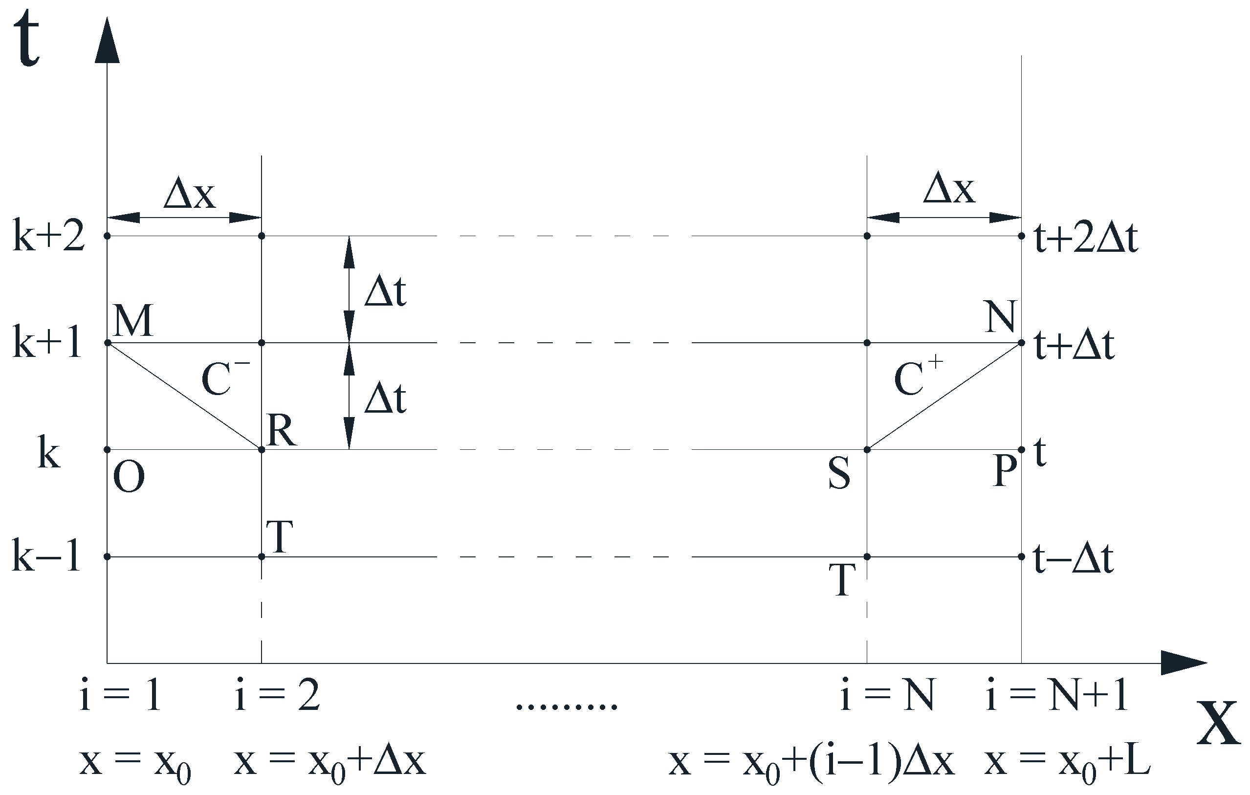
At any internal point D of the characteristics grid (Figure 1), through which two characteristics C+ and C pass, between points D and A as well as D and B, the integration can be performed using the finite linear differences. As a result, the following equations are obtained:
1 c ρ p D p A + v D v A + 2 Δ t ρ R τ A = 0 1 c ρ p D p B + v D v B + 2 Δ t ρ R τ B = 0 .
Solving the system of Equation (5), one can find the final formulas for the calculated values of pressure and velocity at the inner node D of the characteristics grid in the following form:
p D = 1 2 p A + p B + c ρ v A v B + 2 c Δ t R τ B τ A ,
v D = 1 2 v A + v B + 1 c ρ p A p B 2 Δ t ρ R τ A + τ B .
In order to develop a complete solution of the presented task, it is necessary to know the boundary conditions (Figure 2).
When at the i = 1 node (cross-section) of the characteristics grid, the flow velocity v is determined (quickly closing valve) for time t > 0, and at the i = N + 1 node the pressure p is known (reservoir pressure), then:
p M = p R + c ρ v M v R + 2 c Δ t R τ R ,
v N = v S 1 c ρ p N p S 2 Δ t ρ R τ S .
Conversely, if the pressure p was determined as the boundary condition at the i = 1 node of the characteristics grid (reservoir section), and the value of the flow velocity v at the i = N + 1 node (valve section), then:
v M = v R + 1 c ρ p M p R 2 Δ t ρ R τ R ,
p N = p S c ρ v N v S 2 c Δ t R τ S .

3. Modelling Wall Shear Stress

Commonly used quasi-steady, one-dimensional model of friction losses based on the Darcy–Weisbach formula can be used in the case of slow changes in liquid velocity at the pipe cross-section. However, it fails in the case of simulation for fast-changing flow, i.e., in the case of water hammer, the calculated results significantly differ from the results of measurements [29,34,35].
Models of unsteady friction losses, as mentioned in the introduction, can be divided into two groups. The first group consists of models based on the instantaneous values of velocity and acceleration (in literature often named Instantaneous Accelerated Based (IAB) model). The forerunner in this group was the model proposed by Daily et al. [11]. The term associated with the unsteady shear stress at pipe wall is proportional to the acceleration of liquid. This model was later improved by other researchers [12,13]. In this group falls the Brunone et al. model [14], in which the wall shear stress is proportional not only to local derivative of flow velocity but also to its convective derivative:
τ = f q ρ v v 8 + k ρ D 4 v t c v x ,
where: f q —Darcy–Weisbach friction factor; k—empirical unsteady friction coefficient of the IAB model; D—inner pipe diameter.
This model underwent further modifications. Vítkovský et al. [15] rightly pointed out that the acoustic convection term c(∂v/∂x) should be added or subtracted depending on the type of the flow:
τ = f q ρ v v 8 + k ρ D 4 v t + c v v v x .
The next major change was the introduction of separate unsteady friction coefficients for the local derivative kt and convective derivative kx by Ramos et al. [16]:
τ = f q ρ v v 8 + ρ D 4 k t v t + k x c v v v x .
Ramos et al. [16] proved numerically that the expression kt( v/ t) affects the phase shift of pressure waves and that kx( v/ x) affects the rate of attenuation of these waves. The coefficients kt and kx can be calculated on the basis of known experimental results using the method presented by Reddy et al. [17]. The main disadvantage of this approach is the need to determine kt and kx empirically, and that the shape of simulated pressures differs significantly from the shape observed in experiments. Owing to its simplicity, the expression above is often cited and used in practise. It should be noted, however, that the details of the implementation of Equation (14) in the method of characteristics have been described in a comprehensive and clear manner only in one conference article, namely, in reference [15] written by Vítkovský et al. In all other papers the procedure to determine the spatial derivative v x , in particular at the boundary, is unclear. The most recent improvement of this model has been presented by Cao et al. [18]:
τ = f q ρ v v 8 + k ρ D 4 v t + c v v v x k d ρ D 4 2 v x 2 ,
where: k d = μ ρ 716.1 · l n 0.135 · l n R e ; μ —is the second viscosity coefficient.
This model is a further modification of Vítkovský et al. model Equation (13). It takes into account an additional energy dissipation term describing a compression–expansion effect of the fluid. Although the Cao et al. model is an interesting alternative, but this model has a problem with guaranteeing the appropriate dispersion (delay, phase shift) of the pressure wave for low Reynolds numbers [18].
The second group consists of models based on the history of the flow (CBM—convolution-based models). The wall shear stress (and hence the instantaneous coefficient of friction losses) depends here on the frequency of changes in flow and pressure. These models reflect relatively well not only the degree of dissipation of pressure waves but also dispersion. They treat the pressure histories in detail. The forerunner in this group of models has been proposed by Zielke [24], who developed the wall shear stress for transient laminar pipe flow in the form of the sum of quasi-steady shear stress and unsteady contribution, which is an integral convolution of the mean local acceleration of the liquid and a weighting function w(t):
τ t = τ q + τ u = 4 μ R v + 2 μ R 0 t w t u v u t d u ,
where: μ—dynamic viscosity; u—time, used in convolution integral; w(t)—weighting function.
The wall shear stress time domain solution given above is an inverse Laplace transform of the WSS function written in the frequency domain. For laminar flow, this function has a form based on multiplication of a certain frequency-dependent function F ^ s with a partial time derivative of velocity transform. This form was firstly derived and presented by Zielke in his doctoral thesis [36]:
τ ^ s = F ^ s v ^ s t = ρ R j s R 2 ν J 0 j s R 2 ν J 1 j s R 2 ν 2 v ^ s t ,
where: s—Laplace parameter; ν —kinematic viscosity of liquid; j—imaginary unit; J0 and J1—Bessel functions of the first kind (order 0 and 1). Zielke calculated the inverse Laplace transform of F s , which gives the following time domain function:
F t = 4 μ R + 2 μ R n = 1 e κ n 2 t ^ .
A time-domain solution of multiplication of two frequency-dependent functions is a convolutional integral, Equation (16). According to Equation (18), the weighting function in Equation (16) is an infinite series of exponential terms that has the following form for the laminar flow [36]:
w l a m t ^ = n = 1 e κ n 2 t ^ .
where κn in the power of exponent are nth zeros of the Bessel function of type J2. Zielke approximated this function [24,36] in the following way:
w l a m , c l a s s i c t ^ = i = 1 6 m i t ^ i 2 / 2 ,   for   t ^ 0.02 ,
w l a m , c l a s s i c t ^ = i = 1 5 e m i t ^ ,   for   t ^ > 0.02 ,
where: m1 = 0.282095; m2 = −1.25; m3 = 1.057855; m4 = 0.9375; m5 = 0.396696; m6 = −0.351563; n1 = 26.3744; n2 = 70.8493; n3 = 135.0198; n4 = 218.9216; and n5 = 322.5544.
For turbulent flow, much more complicated formulas for impedance have been derived by Vardy and Brown [30] and Zarzycki [37]. Both Zarzycki and Vardy and Brown concluded that in time domain the solution of Equation (16) can be used for turbulent flow, the only difference is that in this flow the weighting function shape depends not only on dimensionless time but also on the initial Reynolds number and characteristic roughness size. In this work, the Vardy and Brown weighting function is used for transient turbulent pipe flow:
w t u r b , c l a s s i c t ^ , R e A * e B * t ^ t ^ ,
where: A * = 1 / 4 π , B*= Reκ/12.86, κ = log10(15.29/Re0.0567)—for smooth pipes [30] and A * = 0.0103 R e ε D 0.39 , B * = 0.352 Re ε D 0.41 for rough pipes [38]; the ratio ε/D is a relative roughness.
In the method of characteristics based on a rectangular grid, the classical numerical solution of the convolution integral Equation (16) can be expressed as:
τ u = 2 μ R j = 1 n 1 v i , j + 1 v i , j w n j Δ t ^ Δ t ^ 2 = 2 μ R j = 1 n 1 v i , n j + 1 v i , n j w j Δ t ^ Δ t ^ 2 .
In the above equation, t ^ is a dimensionless time step, which is:
Δ t ^ = Δ t ν R 2 = Δ x c ν R 2 = L N ν c R 2 = W h N ,
where: Δ t —numerical time step; Δ x —reach length between the nodes; L—pipe length; N—number of reaches (number of analysed pipe cross-sections—spatial nodes); W h = ν L c R 2 —water hammer number [39].
One can see in Equation (21) that the number of iterations required to determine the shear stress increases with the time of simulation of the transient event. In the last forty years, a number of authors showed at least three distinct effective solutions. A simplified recursive solution was first presented by Trikha in 1975 [25]. Its drawback is due to an excessive number of simplifications; thus, it is not suitable for the calculation in a wide range of dimensionless times. Improved forms of recursive formulas have been presented by Kagawa et al. [26] and Schohl [27], respectively:
τ u t + Δ t 2 μ R i = 1 j y i t e n i Δ t ^ + m i e n i Δ t ^ 2 v t + Δ t v t y i t + Δ t ,
τ u t + Δ t 2 μ R i = 1 j y i t e n i Δ t ^ + m i Δ t ^ n i 1 e n i Δ t ^ v t + Δ t v t y i t + Δ t .
Kagawa et al. [26] assumed that the integral of the weighting function can be approximated in the following form:
t t + Δ t e n i ν R 2 u d u e n i ν R 2 t + Δ t 2 t t + Δ t d u .
Schohl [27] calculated the same integral symbolically:
t t + Δ t e n i ν R 2 u d u = R 2 n i ν e n i ν R 2 t + Δ t e n i ν R 2 t .
It is worth noting that in all efficient solutions the weighting function needs to be written as a finite sum of exponential terms:
w e f f . = m i e n i t ^ .
Recently, Vardy-Brown [40] pointed out an overlooked error in a classical computationally inefficient methodology of Equation (21) and suggested calculating the wall shear stress by using the following equation:
τ u = 2 μ R j = 1 n 1 v i , n j + 1 v i , n j j 1 Δ t ^ j Δ t ^ w t ^ d t ^ .
That is why in this work a corrected solution of CBM is used, which is an effective counterpart of the above-corrected Equation (28):
τ u = 2 μ R i = 1 j y i t A i + η B i v t + Δ t v t + 1 η C i v t v t Δ t y i t + Δ t ,
where: η—correction factor. The details of the derivation of Equation (29) can be found in [28]. The constants in the formula above are calculated as follows:
A i = e n i Δ t ^ ;  B i = m i Δ t ^ n i 1 A i ; C i = A i B i ,
where: n i and m i —coefficients describing the effective weighting functions. The algorithm for determining the values of these coefficients is presented in Appendix A. In this efficient formula, Equation (29), the effective weighting function, does not need to have an extended range of applicability in dimensionless time to correctly model transient flows. For the dimensionless time range from 0 to Δ t ^ , the integral for the effective weighting function is replaced with either the integral from the classical laminar-flow weighting function according to the Zielke Equation (19) or the turbulent-flow weighting function according to Vardy-Brown Equation (20) (depending on the type of flow that takes place: laminar or turbulent) as presented in Figure 3. In addition to the standard model in which the friction term is calculated in the same way at each node of the numerical grid of characteristics, this work also investigates a model lumping the unsteady friction factor only at the boundary nodes of the pipe. The author of this approach is Johnston, who described its basics in [32]. The lumping of τ u at the sections i = 1 and i = N + 1 significantly shortens the numerical computational time, because in all other nodes calculations are based on the quasi-steady solution ( τ q ) . However, this approach requires modification of the velocity values v M , c and v N , c at the boundary nodes, as follows:
v M , c = 1 2 v M + p M ρ c ;   v N , c = 1 2 v N + p N ρ c ,
Equation (31) is used to determine the lumped values of the wall shear stress at the boundary nodes. This model has been recently investigated by Xu et al. [41] with an objective to develop an ultrafast numerical solution based on a gridless scheme.
In some recent works [31,42], the impact of (i) the number of terms describing the effective weighting function, (ii) the scope of applicability in dimensionless time, and (iii) the lumped friction model, were analysed. The main conclusion from these studies was that the time range of applicability of the effective weighting function in order to model unsteady pressure events with sufficient accuracy should be from t ^ to t ^ ·103. This indicates that the effective weighting functions do not need to be composed of many exponential terms, as only two are sufficient and it is less than in the well-known effective weighting function presented by Trikha [25]. In addition, Bergant et al. [43] found that CBM cannot produce a small-frequency shift in pressure history observed in experimental results. This deficiency can be eliminated either by inclusion of the momentum correction factor in the inertia term of Equation (3) or by using the measured pressure wave propagation speed.

4. Analysis of the Results

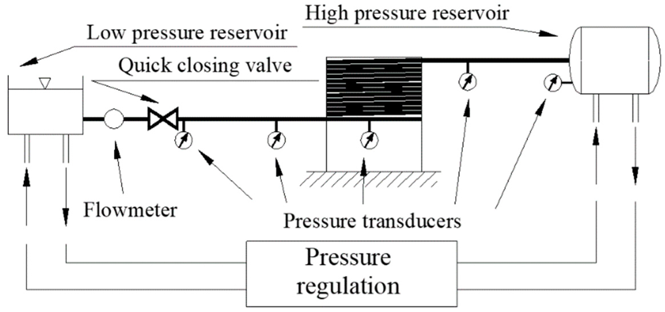
The experimental tests of Adamkowski and Lewandowski [29], in which a simple water hammer event in a reservoir–pipeline–valve system occurred due to rapid closure of the valve, were selected for our comparison analysis. A test stand was located at the Institute of Fluid-Flow Machinery in Gdańsk, Poland, the main element of which was a long metal copper pipe. The pipe was 98 m long and a large part of it was wound on a steel cylinder (with a diameter of about 1.6 m; please note that pipe was rigidly mounted to the cylinder coating in order to minimise its vibrations), as can be seen in Figure 4. Horizontal parts of the pipeline (not coiled) were constrained with the help of steel clamps, spaced at about every 0.4 m to the concrete base of the laboratory. The upstream end tank is a pressure reservoir with a capacity of 1.6 m3. Its main role was to maintain constant pressure during steady-flow conditions and near-constant pressure under transient operation. The test rig was equipped with absolute semiconductor pressure transducers (measuring range from 0 to 4 MPa; transmitted frequency band from 0 to 2 kHz, and precision class equal to 0.2%), turbine flowmeter (range of 1.5 m3/h and precision class of 1%), ball valve (installed between the quick-closing valve and flowmeter), and feed pump (with adjustable rotational speed). The two elements mentioned (ball valve and feed pump) were used to adjust required initial conditions in the system. A water hammer event was generated by a quick-closing valve in which the closing time was minimised using a specially designed spring driving mechanism.
Detailed values describing the basic parameters of the experimental apparatus are presented in Table 1, where: T v c —valve full closing time; T —temperature; e —pipe wall thickness. These parameters were used as input parameters in a proprietary computer program written in the MATLAB environment.
Comparative analysis was performed for nine test cases. Additional details on the boundary and initial conditions necessary to model these cases are summarized in Table 2.
Water hammer simulation, especially with the use of the classical full-convolutional integral and its computationally ineffective solution, takes a long time. Therefore, the comparative studies were limited to computational time of t = 5.5 s. This time covers eighteen water hammer periods (t/(4L/c)), more than enough for an adequate comparison study.
The influence of the mesh refinement of the method of characteristics on the obtained results was also examined. The results obtained for the simplified CBM model (SM—Equation (29)) and the lumped friction model (LFM—Equation (31)) were analysed for meshes with the following densities: coarse mesh N = 32 (nodes ≈ 77,000); N = 52 (nodes ≈ 201,000), N = 102 (nodes ≈ 766,000), and very fine mesh N = 202 (nodes ≈ 2,989,000). The N parameter influences not only the mesh refinement along its length, but also the time step ∆t, which determines the mesh refinement in time (due to Courant–Friedrichs–Lewy CFL stability condition):
Δ x = L / N and Δ t = Δ x / c .
All the results using the classical computationally ineffective solution of the convolutional integral (FULL CONV.) were realised only for N = 32. In this case, to perform 5.5 s simulation required about an hour; thus, in order to save the time, it was decided not to repeat these tests for fine meshes.
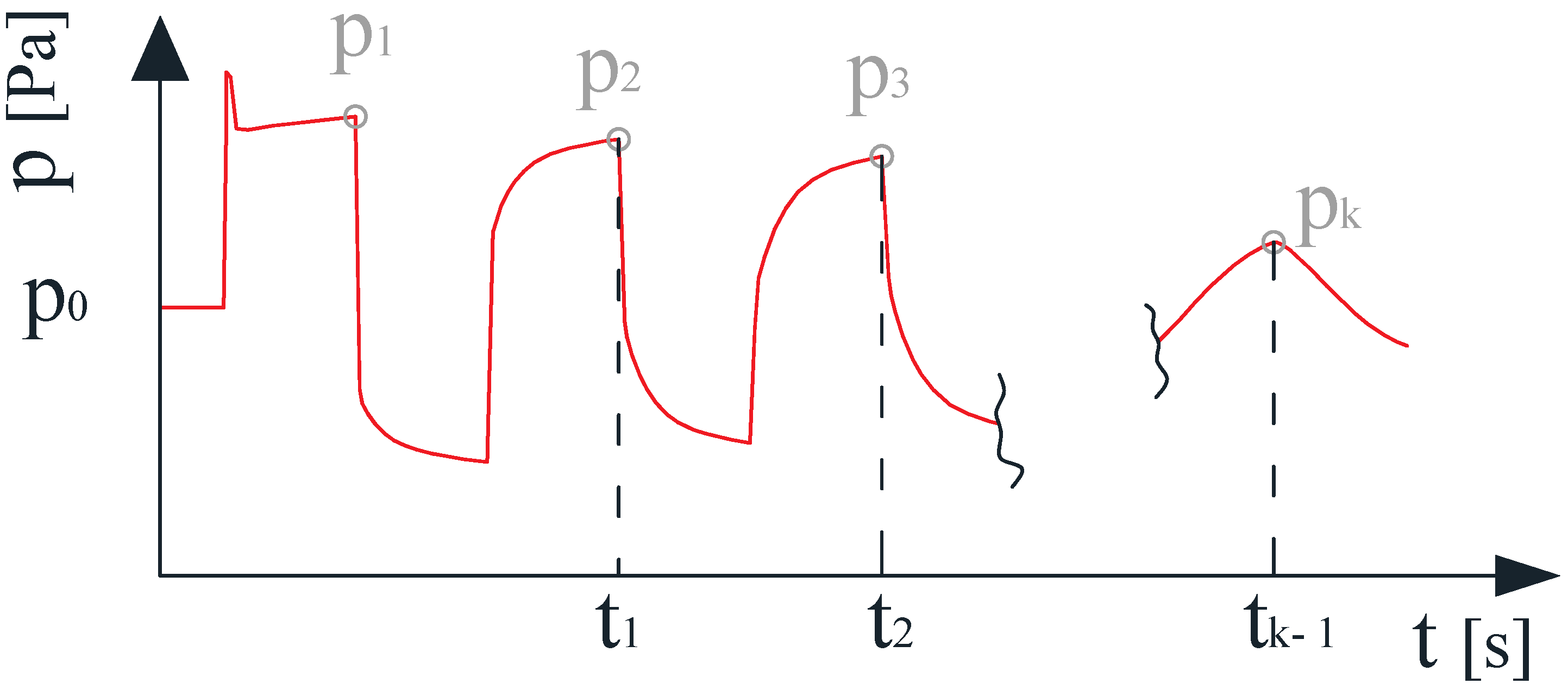
When analysing the results of experimental studies by Adamkowski and Lewandowski, one can notice an atypical pressure peak at the first amplitude of all the runs (Figure 5) to a value much higher than the predicted value, which can be calculated from the Joukowsky Equation (1). These short-duration peaks at the first pressure amplitude plateau are most probably the result of undesired mechanical vibrations produced by the valve closing drive [44]. They are quickly damped out for all types of supports and are present only at the first pressure pulse and do not influence further water hammer pressure oscillations. The other reason for these peaks (initial disturbances) can be probably linked to the system response due to the excitation from the step-load induced by the fast-closing valve [45]. Another source of such peaks can be explained to be the result of the type of valve used [46,47]. The use of the globe valve instead of the ball valve allows elimination of their presence in experiments. These peaks, however, with the correct restraint of the valve and pressure measurement sections, should not occur; therefore, the maximum pressure values from these peaks are not taken into account in the quantitative analysis. The maximum bulk pressure pulse is taken into consideration, as illustrated in Figure 5. At subsequent amplitudes, the observed maximum pressure values and the times in which these maximums appeared were taken into account (see Figure 6).
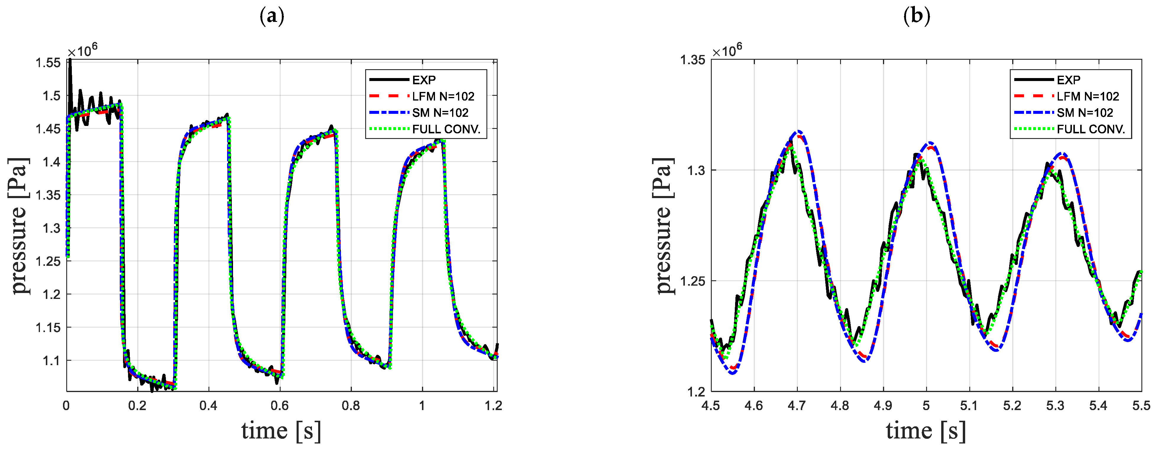
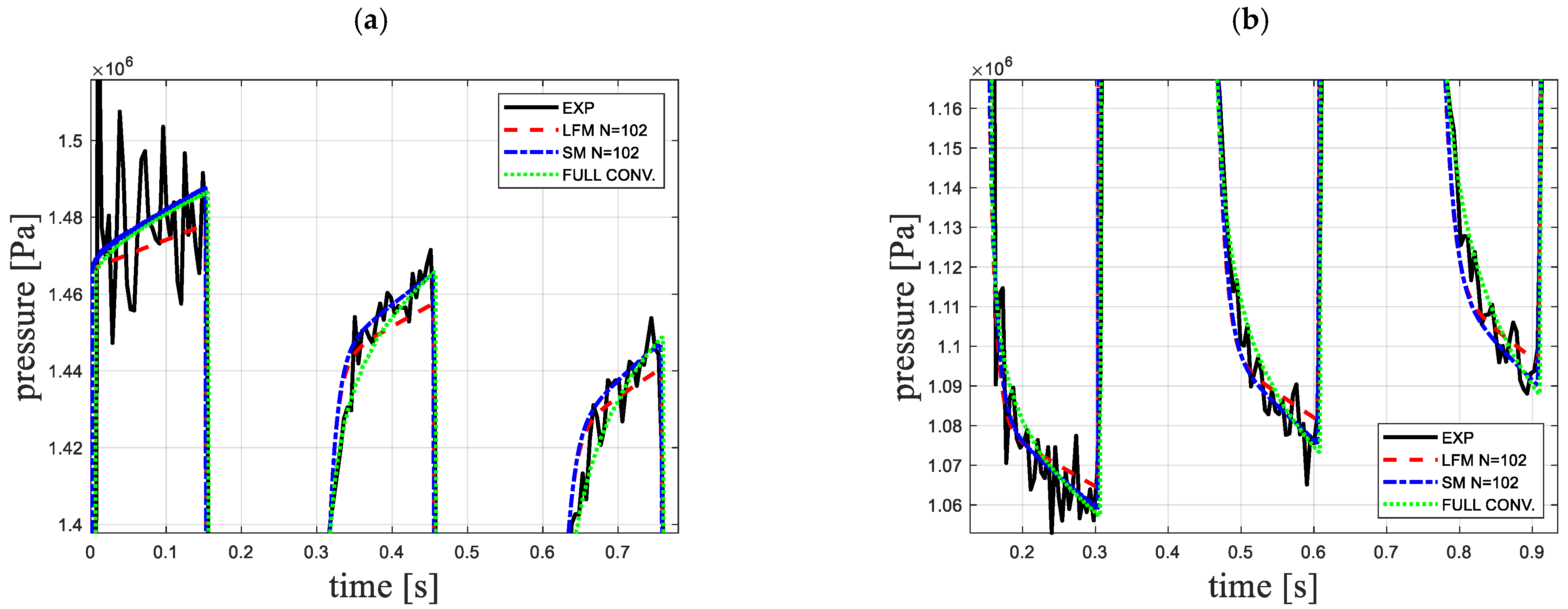
As an example, the simulation results (N = 102) for Case 02 (Re = 2750) are shown in Figure 7. On the other hand, Figure 8 shows the enlargement of the three initial pressure amplitude crests (Figure 8a) and valleys (Figure 8b). It can be seen that the LFM slightly underestimates the pressure in the initial period of the water hammer event and delicately distorts the valleys of these amplitudes. However, from the fourth amplitude to the eighteenth amplitude, there is a reasonable match. The analysed quantitative parameters were calculated from the following formulas:
E p = i = 1 18 p i s p i e p i e 100 % 18 ; E t = i = 1 17 t i s t i e t i e 100 % 17 .
Note: In the time analysis, while calculating the Et parameters, the focus was on the times of the peaks at successive amplitudes starting from the second (excluding first). It is related to the registered fact of “overpressures” and their influence on this parameter on the first amplitude; if they were taken into account, the error Et value would be distorted.
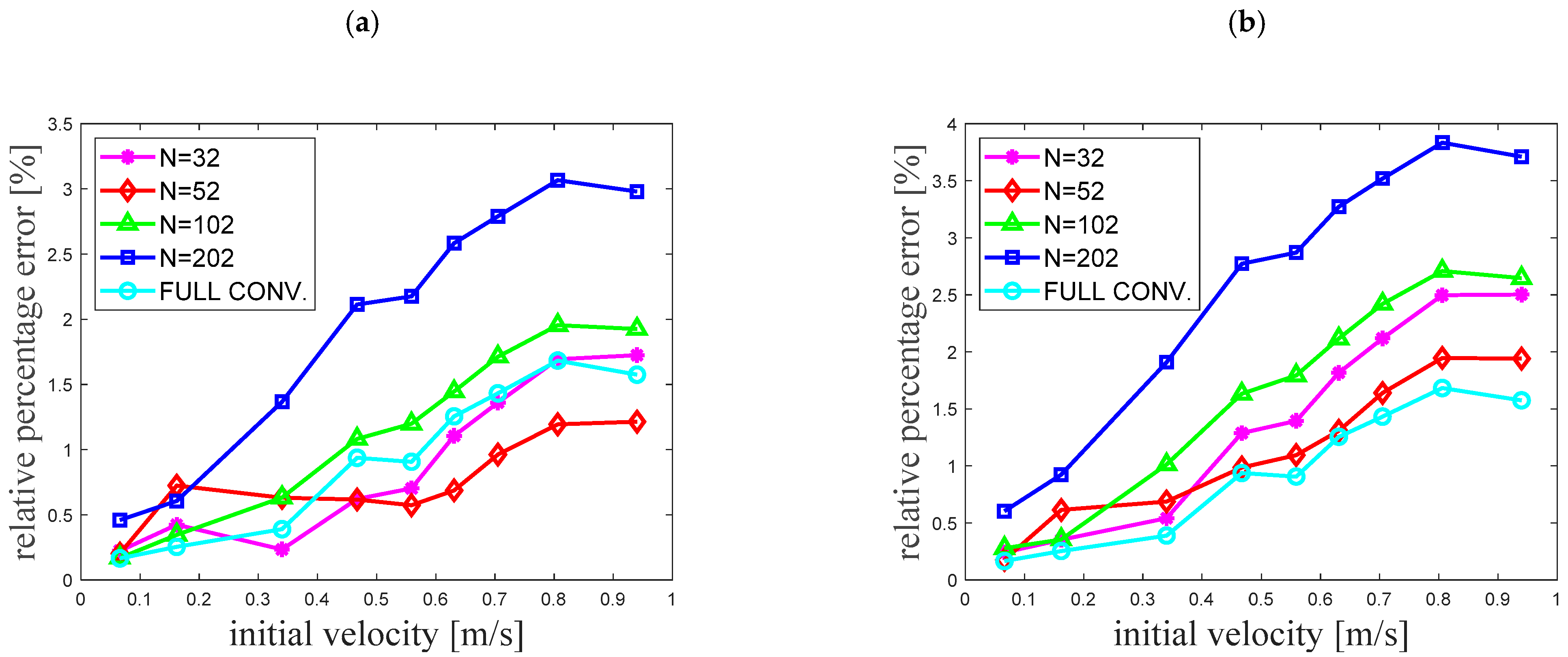
The final results of the Ep errors from all simulation tests are summarised graphically (Figure 9), while the results of the Et errors are summarised in Table 3.
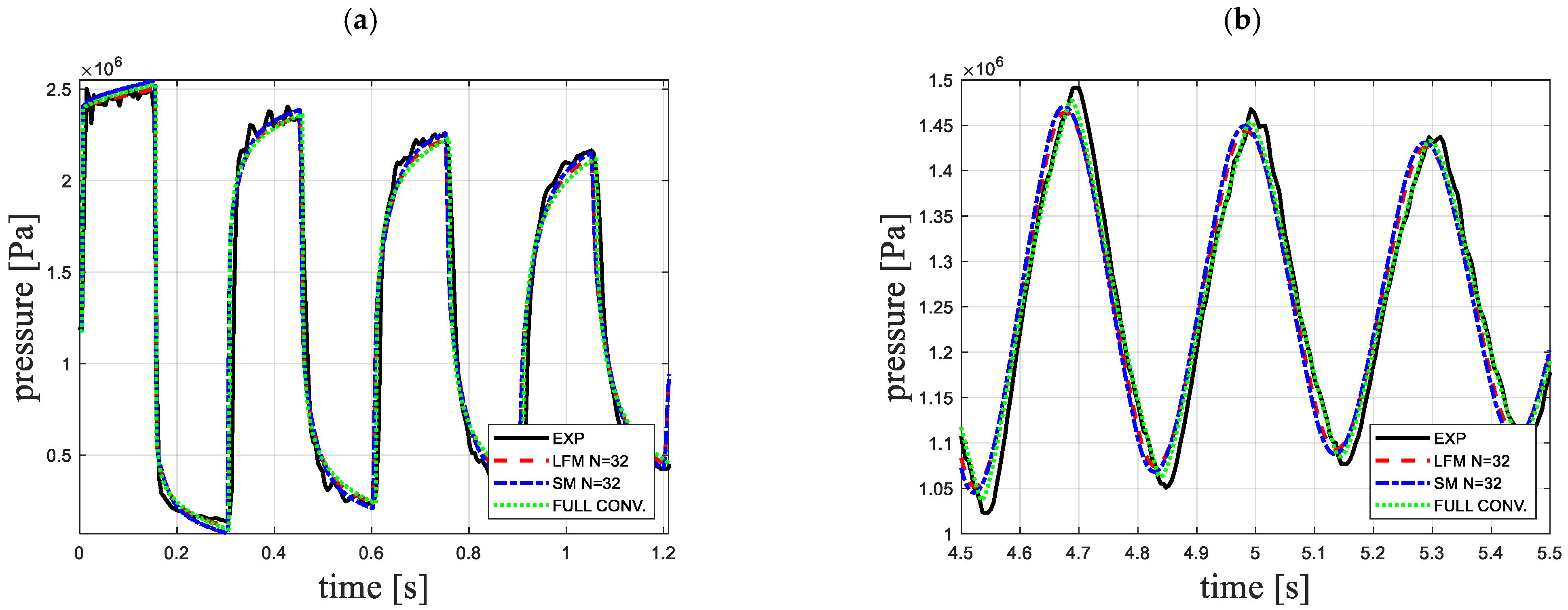
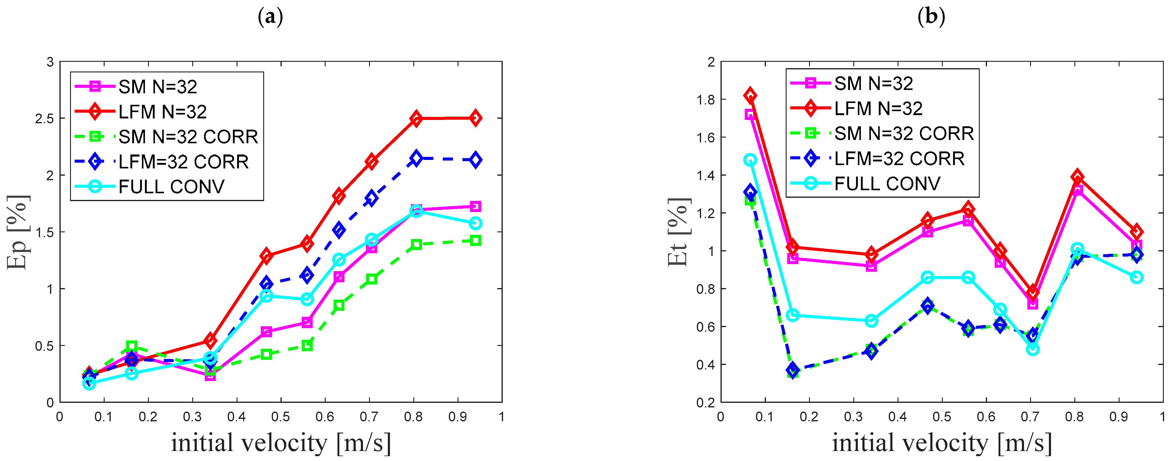
Table 3 shows that the time consistency Et of the transient pressure waveforms simulated in the way proposed in this work was worse than the waveforms simulated with the full-convolutional integral. However, it was noticed during the implementation of these simulations that this disadvantage representing the simplified simulations can be easily minimised. Namely, during the simulation for N = 32, assuming only one parameter other than in the case of the waveform simulated with the full convolution (ineffective), this parameter is a speed of pressure wave propagation c. Assuming the value of ce = 1.01 * cfc (one percent higher) during effective simulations, a significant improvement in the temporal consistency of the simulated waveforms is obtained (compare exemplary results presented in Figure 10 and Figure 11 for Case 09—Re = 15,850), while maintaining very good agreement of the modelling of the maximum pressures (Figure 11). This necessity to modify the speed of pressure wave propagation can be explained by the use of a simplified weighting function in the calculations (made up of only two exponential terms). The quantitative results obtained from the additional simulations performed, presented in Figure 12, also indicate the improvement of the compliance fit. This improvement confirms similar findings by Bergant et al. [44].
Completed extensive simulations have shown that modelling of hydraulic resistance during water hammer using the SM does not have to be a very complicated issue. The main conclusions of the research carried out are as follows:
-
Use of simplified weighting functions, as shown in this paper, built from only two exponential terms, guarantees the results of a high agreement with the experimental results;
-
Division of the pipeline along its length into 52 computational reaches guarantees the results with the lowest Ep errors;
-
The smallest errors of parameter Et representing the time compliance of the simulated amplitudes were obtained using the largest division, i.e., 202 elements. It should be noted, however, that the application of a simple correction in the form of a slight increase (decrease) in the value of the pressure wave speed c significantly reduces this error.
Apart from the advantages, there are also disadvantages of the above-examined procedure:
-
Necessity to use a constant time step (in a way, it is also a disadvantage of the characteristics method);
-
Necessity of one-time analytical calculation of appropriate values of the weighting function coefficients (from the formulas presented in the Appendix A);
-
Owing to the filtering of the upper range of the weighting function (from 103 · t ^ to ∞), this method can only be used for modelling water hammer. Thus, preliminary analyses showed that it is not suitable for modelling typically unidirectional flows (accelerated and delayed).
Further work should be aimed at an attempt to completely replace the weighting function built from a sum of exponential expressions with another simple function.

5. Conclusions

This paper investigates the performance of the computationally effective and accurate convolutional-based unsteady skin friction model (CBM) developed recently by Urbanowicz [31]. The weighting function is constructed from just two exponential terms, although then the coefficients m i and n i need to be calculated from the formulas given in the Appendix A. These coefficients are a function of the assumed dimensionless time step Δ t ^ in the numerical method. The simplification of the weighting function in conjunction with the corrected effective method for solving the convolution integral enables the determination of resistances from the final formulas of mathematical complexity similar to the IAB model. Contrary to the IAB models, in the analysed CBM approach, there is no need to calibrate the parameters describing the wall shear stress. A further possibility to simplify the modelling of unsteady resistance may be to use a model that lumps unsteady friction at the boundary nodes. The simulations carried out with the use of Johnston’s model showed that the analysed transient waveforms were simulated with sufficient compliance with this model, which also used the two-term weighting function. Thus, we do hope that the validated simplifications of the CBM model implemented in this paper will find wider practical application, for example, in commercial programs for modelling transient flows in hydraulic pipe networks.

Author Contributions

Conceptualisation, K.U., A.B. and M.S.; methodology, K.U., A.B. and M.S.; software, K.U., A.D. and M.K. (Mykola Karpenko); validation, M.K. (Michał Kubrak) and A.K.; data curation, K.U. and A.D.; formal analysis, K.U., M.K. (Michał Kubrak) and A.K.; investigation, K.U., M.K. (Michał Kubrak) and A.K.; resources, M.K. (Mykola Karpenko), A.D. and M.S.; writing—original draft preparation, K.U. and A.B.; writing—review and editing, K.U., A.B., M.S. and M.K. (Michał Kubrak); visualisation, K.U., A.D. and M.K. (Mykola Karpenko); supervision, K.U., A.K. and A.B.; project administration, K.U. and M.S.; funding acquisition, K.U., M.S. and A.D. All authors have read and agreed to the published version of the manuscript.

Funding

A. Bergant gratefully acknowledges the support of Slovenian Research Agency (ARRS) conducted through the research project L2-1825 and the programme P2-0162.

Data Availability Statement

The code generated during the study and experimental data are available from the corresponding author by request.

Conflicts of Interest

The authors declare no conflict of interest.

Nomenclature

Ai, Bi and Ciunsteady friction coefficients (-)
cpressure wave speed (m/s)
Dpipe internal diameter (m)
Ep and Etpressure and time compliance parameters (%)
epipe-wall thickness (m)
ftransient friction factor (-)
fqDarcy–Weisbach friction factor (-)
gacceleration due to gravity (m/s2)
jimaginary unit (-)
kempirical unsteady friction coefficient of the IAB model (-)
Lpipe length (m)
mi and nifrictional weighting function coefficients (-)
Nnumber of computational reaches (-)
ppressure (Pa)
pRreservoir pressure (Pa)
Rpipe internal radius (m)
Re0initial Reynolds number (-)
sLaplace parameter (1/s)
Ttemperature in Celsius degrees (°C)
ttime (s)
udummy variable (s)
Whwater hammer number (-)
wweighting function of unsteady friction (-)
vaverage flow velocity (m/s)
v0initial liquid velocity (m/s)
xspace coordinate (m)
yitime dependent historical velocity effect (m/s)
Δtnumerical time step (s)
Δ t ^ dimensionless time step (-)
Δxnumerical spatial step (m)
Δvvelocity change at the valve (m/s)
εpipe-wall roughness (m)
ηcorrection factor of unsteady friction (-)
κnnth zeros of the Bessel function of type J2 (-)
μdynamic viscosity (Pa·s)
μ second viscosity coefficient (Pa·s)
νkinematic viscosity of liquid (m2/s)
ρliquid density (kg/m3)
τwall shear stress (Pa)
Acronyms
CBMconvolution-based model
CFMCourant–Friedrichs–Lewy condition
CORRcorrected
EXPexperimental
FULL CONVineffective solution of the convolutional integral
HDPEhigh-density polyethylene
IABinstantaneous acceleration-based model
LFMlumped friction method
MOCmethod of characteristics
PVCpolyvinyl chloride
SMstandard method

Appendix A. Estimation of the Weighting Function Coefficients

The estimation of the weighting function coefficients is performed at the initial stage of transient simulations (set-up of the initial conditions) by the following procedure:
I. First calculate the constant time step ∆t, next the dimensionless time step:
Δ t ^ = Δ t ν R 2 = W h N ,
where: W h = ν L c R 2 is a water hammer number.
II. When a dimensionless time step is known, calculate efficient weighting function coefficients m1, m2 and n1, n2 (for a simplified two-term function):
(a)
m1 calculation when Δ t ^ 10 4 :
m 1 = 0 . 03234 Δ t ^ 0 . 5 + 48 . 35 Δ t ^ 0 . 5437 + 9 . 717 Δ t ^ 3 . 85 1 . 318 ,
m1 calculation when Δ t ^ > 10 4 :
m 1 = 0 . 148 exp Δ t ^ 188 . 8 + 0 . 3227 exp Δ t ^ 1316 + 0 . 8039 exp Δ t ^ 5728 + 2 . 458 exp Δ t ^ 19 , 270 + 1 ,
(b)
m2 calculation when Δ t ^ 10 4 :
m 2 = 0 . 1963 Δ t ^ 0 . 5 + 2 . 88 Δ t ^ 3 . 575 0 . 2661 Δ t ^ 5 . 276 0 . 2351 ,
m2 calculation when Δ t ^ > 10 4 :
m 2 = 2 . 214 exp Δ t ^ 62 . 02 + 4 . 155 exp Δ t ^ 386 . 6 + 7 . 929 exp Δ t ^ 2191 + 20 . 485 exp Δ t ^ 12 , 570 + 1 ,
(c)
n1 calculation when Δ t ^ 10 5 :
n 1 = 0 . 001476 Δ t ^ 1 + 0 . 1203 Δ t ^ 0 . 5 + 526 . 7 Δ t ^ 0 . 5567 + 6 . 091 ,
n1 calculation when Δ t ^ > 10 5 :
n 1 = 9 . 317 exp Δ t ^ 4459 + 87 exp Δ t ^ 29 , 320 + 188 . 1 exp Δ t ^ 104 , 300 + 477 . 43 exp Δ t ^ 290 , 500 + 26 . 3744 ,
(d)
n2 calculation when Δ t ^ 10 4 :
n 2 = 0 . 09021 Δ t ^ 1 + 0 . 382 Δ t ^ 0 . 4592 + 218 . 1 Δ t ^ 0 . 2615 ,
n2 calculation when Δ t ^ > 10 4 :
n 2 = 56 . 56 exp Δ t ^ 79 . 71 + 136 . 5 exp Δ t ^ 489 . 6 + 396 . 7 exp Δ t ^ 2880 + 1903 . 3 exp Δ t ^ 15 , 760 + 70 . 8493 .
III. Calculate correction coefficient η:
(a)
For laminar flow when Δ t ^ 0.02 :
η = 2 m 1 z Δ t ^ 0.5 + m 2 z Δ t ^ 1 + 2 3 m 3 z Δ t ^ 1.5 + 1 2 m 4 z Δ t ^ 2 + 2 5 m 5 z Δ t ^ 2.5 + 1 3 m 6 z Δ t ^ 3 i = 1 2 m i n i 1 e n i Δ t ^ ,
where: m1z = 0.282095; m2z = −1.25; m3z = 1.057855; m4z = 0.9375; m5z = 0.396696; and m6z = −0.351563.
For laminar flow when Δ t ^ > 0.02 :
η = C 1 + C 2 i = 1 2 m i n i 1 e n i Δ t ^ ,
where:
C 1 = 2 m 1 z 0.02 0.5 + m 2 z 0.02 1 + 2 3 m 3 z 0.02 1.5 + 1 2 m 4 z 0.02 2 + 2 5 m 5 z 0.02 2.5 + 1 3 m 6 z 0.02 3 ,
C 2 = i = 1 5 1 e n i z Δ t ^ n i z i = 1 5 1 e n i z 0.02 n i z ,
and: n1z = 26.3744; n2z = 70.8493; n3z = 135.0198; n4z = 218.9216; and n5z = 322.5544;
(b)
For turbulent flow (Re > 2320):
η = A * π B * e r f Δ t ^ B * i = 1 2 m i n i s 1 e n i s Δ t ^ ,
where:
A * = 1 4 π ;   B * = R e κ 12.86 ;   κ = log 10 15.29 / R e 0.0567 ,
nis is scaled coefficient using a universal scaling procedure:
n 1 s = n 1 171.6545 + B * ;   n 2 s = n 2 171.6545 + B * .
IV. Calculate the constants in the efficient solution of convolution integral
A 1 = e n 1 Δ t ^ ; B 1 = m 1 Δ t ^ n 1 1 A 1 ; C 1 = A 1 B 1 ,
A 2 = e n 2 Δ t ^ ; B 2 = m 2 Δ t ^ n 2 1 A 2 ; C 2 = A 2 B 2   .
Finally, the temporary unsteady friction factor during simulations is calculated by the following equation:
f t + Δ t = f q , t + Δ t + 32 ν D v t + Δ t v t + Δ t i = 1 2 y i t A i + η B i v t + Δ t v t + 1 η C i v t v t Δ t y i t + Δ t
Note that:
when calculated velocity is in range −10−5 < v < 10−5, assume v = −10−5 if it has a minus sign and v = 10−5 when it has a positive sign (to avoid division by zero);
select optimal number of grid points through the pipe axis; it should generally not exceed N = 52;
set yi(t) = 0 as an initial condition (for steady flow).

References

  1. Pothof, I.; Karney, B. Guidelines for Transient Analysis in Water Transmission and Distribution Systems. In Water Supply System Analysis—Selected Topics; IntechOpen: London, UK, 2012. [Google Scholar] [CrossRef] [Green Version]
  2. Jansson, M.; Andersson, M.; Karlsson, M. High-speed imaging of water hammer cavitation in oil–hydraulic pipe flow. Fluids 2022, 7, 102. [Google Scholar] [CrossRef]
  3. Mousavifard, M.; Norooz, R. Numerical analysis of transient cavitating pipe flow by Quasi 2D and 1D models. J. Hydraul. Res. 2022, 60, 295–310. [Google Scholar] [CrossRef]
  4. Warda, H.A.; Wahba, E.M.; Salah El-Din, M. Computational Fluid Dynamics (CFD) simulation of liquid column separation in pipe transients. Alex. Eng. J. 2020, 59, 3451–3462. [Google Scholar] [CrossRef]
  5. Zhou, L.; Li, Y.; Zhao, Y.; Ou, C.; Zhao, Y. An accurate and efficient scheme involving unsteady friction for transient pipe flow. J. Hydroinform. 2021, 23, 879–896. [Google Scholar] [CrossRef]
  6. Andrade, D.M.; Rachid, F.B.F. A versatile friction model for Newtonian liquids flowing under unsteady regimes in pipes. Meccanica 2022, 57, 43–72. [Google Scholar] [CrossRef]
  7. Guerrero, B.; Lambert, M.F.; Chin, R.C. Extension of the 1D Unsteady Friction Model for Rapidly Accelerating and Decelerating Turbulent Pipe Flows. J. Hydraul. Eng. 2022, 148, 04022014. [Google Scholar] [CrossRef]
  8. Santos, J.D.B.; Anjos, G.R.; Savi, M.A. An investigation of fluid-structure interaction in pipe conveying flow using reduced-order models. Meccanica 2022. [Google Scholar] [CrossRef]
  9. Cherian, R.M.; Sajikumar, N.; Sumam, K.S. Influence of Fluid–Structure Interaction on Pressure Fluctuations in Transient Flow. J. Pipeline Syst. Eng. Pract. 2021, 12, 04021002. [Google Scholar] [CrossRef]
  10. Henclik, S. Application of the shock response spectrum method to severity assessment of water hammer loads. Mech. Syst. Signal Process. 2021, 157, 107649. [Google Scholar] [CrossRef]
  11. Daily, J.W.; Hankey, W.L.; Olive, R.W.; Jordaan, J.M. Resistance coefficients for accelerated and decelerated flows through smooth tubes and orifices. Trans. ASME 1956, 78, 1071–1077. [Google Scholar] [CrossRef]
  12. Carstens, M.R.; Roller, J.E. Boundary-shear stress in unsteady turbulent pipe flow. J. Hydraul. Div. ASCE 1959, 95, 67–813. [Google Scholar] [CrossRef]
  13. Safwat, H.H.; van den Polder, J. Experimental and analytic data correlation study of water column separation. J. Fluids Eng. 1973, 95, 91–97. [Google Scholar] [CrossRef]
  14. Brunone, B.; Golia, U.M.; Greco, M. Some remarks on the momentum equations for fast transients. In Proceedings of the Hydraulic Transients with Column Separation (9th and Last Round Table of the IAHR Group), IAHR, Valencia, Spain, 4–6 September 1991; pp. 201–209. [Google Scholar]
  15. Vítkovský, J.; Lambert, M.; Simpson, A.; Bergant, A. Advances in unsteady friction modelling in transient pipe flow. In Proceedings of the 8th International Conference on Pressure Surges, The Hague, The Netherlands, 12–14 April 2000; pp. 471–482. [Google Scholar]
  16. Ramos, H.; Covas, D.; Borga, A.; Loureiro, D. Surge damping analysis in pipe systems: Modelling and experiments. J. Hydraul. Res. 2004, 42, 413–425. [Google Scholar] [CrossRef]
  17. Reddy, H.P.; Silva-Araya, W.F.; Chaudhry, M.H. Estimation of decay coefficients for unsteady friction for instantaneous, acceleration-based models. J. Hydraul. Eng. 2012, 138, 260–271. [Google Scholar] [CrossRef]
  18. Cao, Z.; Wang, Z.; Deng, J.; Guo, X.; Lu, L. Unsteady friction model modified with compression–expansion effects in transient pipe flow. J. Water Supply Res. Technol.-Aqua 2022, 71, 330–344. [Google Scholar] [CrossRef]
  19. Hu, Y.; Zhou, L.; Pan, T.; Fang, H.; Li, Y.; Liu, D. Godunov-type solutions for free surface transient flow in pipeline incorporating unsteady friction. J. Water Supply: Res. Technol.-Aqua 2022, 71, 546–562. [Google Scholar] [CrossRef]
  20. Pan, T.; Zhou, L.; Ou, C.; Wang, P.; Liu, D. Smoothed particle hydrodynamics with unsteady friction model for water hammer pipe flow. J. Hydraul. Eng. 2022, 148, 04021057. [Google Scholar] [CrossRef]
  21. Zhou, L.; Li, Y.; Karney, B.; Cheng, Y. Godunov-type solutions for transient pipe flow implicitly incorporating Brunone unsteady friction. J. Hydraul. Eng. 2021, 147, 04021021. [Google Scholar] [CrossRef]
  22. Abdeldayem, O.M.; Ferràs, D.; van der Zwan, S.; Kennedy, M. Analysis of unsteady friction models used in engineering software for water hammer analysis: Implementation Case in WANDA. Water 2021, 13, 495. [Google Scholar] [CrossRef]
  23. Wan, W.; Mehmood, K. Instantaneous acceleration-based modeling of pumping systems response under transient events. Int. J. Mech. Sci. 2022, 224, 107354. [Google Scholar] [CrossRef]
  24. Zielke, W. Frequency-dependent friction in transient pipe flow. J. ASME 1968, 90, 109–115. [Google Scholar] [CrossRef]
  25. Trikha, A.K. An efficient method for simulating frequency-dependent friction in transient liquid flow. J. Fluids Eng. ASME 1975, 97, 97–105. [Google Scholar] [CrossRef]
  26. Kagawa, T.; Lee, I.; Kitagawa, A.; Takenaka, T. High speed and accurate computing method of frequency-dependent friction in laminar pipe flow for characteristics method. Trans. Jpn. Soc. Mech. Eng. Part A 1983, 49, 2638–2644. [Google Scholar] [CrossRef]
  27. Schohl, G.A. Improved approximate method for simulating frequency—Dependent friction in transient laminar flow. J. Fluids Eng. ASME 1993, 115, 420–424. [Google Scholar] [CrossRef]
  28. Urbanowicz, K. Fast and accurate modelling of frictional transient pipe flow. Z. Angew. Math. Mech. 2018, 98, 802–823. [Google Scholar] [CrossRef]
  29. Adamkowski, A.; Lewandowski, M. Experimental examination of unsteady friction models for transient pipe flow simulation. J. Fluids Eng. 2006, 128, 1351–1363. [Google Scholar] [CrossRef]
  30. Vardy, A.E.; Brown, J.M.B. Transient turbulent friction in smooth pipe flows. J. Sound Vib. 2003, 259, 1011–1036. [Google Scholar] [CrossRef]
  31. Urbanowicz, K. Modern modeling of water hammer. Pol. Marit. Res. 2017, 24, 68–77. [Google Scholar] [CrossRef]
  32. Johnston, D.N. Efficient methods for numerical modelling of laminar friction in fluid lines. J. Dyn. Syst. Meas. Control ASME 2006, 128, 829–834. [Google Scholar] [CrossRef]
  33. Wylie, E.B.; Streeter, V.L.; Suo, L. Fluid Transients in Systems; Prentice-Hall Inc.: Englewood Cliffs, NJ, USA, 1993. [Google Scholar]
  34. Bergant, A.; Simpson, A.R.; Vítkovský, J.P. Developments in unsteady pipe flow friction modelling. J. Hydraul. Res. 2001, 39, 249–257. [Google Scholar] [CrossRef] [Green Version]
  35. Vítkovský, J.P.; Bergant, A.; Simpson, A.R.; Lambert, M.F. Systematic evaluation of one-dimensional unsteady friction models in simple pipelines. J. Hydraul. Eng. 2006, 132, 696–708. [Google Scholar] [CrossRef] [Green Version]
  36. Zielke, W. Frequency-Dependent Friction in Transient Pipe Flow. Doctoral Thesis, University of Michigan, Ann Arbor, MI, USA, 1966. [Google Scholar]
  37. Zarzycki, Z. On weighting function for wall shear stress during unsteady turbulent pipe flow. In Proceedings of the 8th International Conference on Pressure Surges, BHR Group, The Hague, The Netherlands, 12–14 April 2000; pp. 529–543. [Google Scholar]
  38. Vardy, A.E.; Brown, J.M.B. Transient turbulent flow in fully-rough pipes. J. Sound Vib. 2004, 270, 233–257. [Google Scholar] [CrossRef]
  39. Urbanowicz, K.; Bergant, A.; Karadzić, U.; Jing, H.; Kodura, A. Numerical investigation of the cavitating flow for constant water hammer number. J. Phys. Conf. Ser. 2021, 1736, 012040. [Google Scholar] [CrossRef]
  40. Vardy, A.E.; Brown, J.M.B. Evaluation of unsteady wall shear stress by Zielke’s method. J. Hydraul. Eng. 2010, 136, 453–456. [Google Scholar] [CrossRef]
  41. Xu, Y.; Jiao, Z.; Zhao, L. Fast meshless solution with lumped friction for water hammer. In Proceedings of the BATH/ASME 2020 Symposium on Fluid Power and Motion Control, Virtual, 9–11 September 2020. FPMC2020-2789, V001T01A043. [Google Scholar] [CrossRef]
  42. Urbanowicz, K. Analytical expressions for effective weighting functions used during simulations of water hammer. J. Theor. Appl. Mech. 2017, 55, 1029–1040. [Google Scholar] [CrossRef] [Green Version]
  43. Bergant, A.; Karadžić, U.; Vítkovský, J.P.; Vušanović, I.; Simpson, A.R. A discrete gas cavity model that considers the frictional effects of unsteady pipe flow. Stroj. Vestn.-J. Mech. Eng. 2005, 51, 692–710. [Google Scholar]
  44. Adamkowski, A.; Henclik, S.; Janicki, W.; Lewandowski, M. The influence of pipeline supports stiffness onto the water hammer run. Eur. J. Mech. B/Fluids 2016, 61, 297–303. [Google Scholar] [CrossRef] [Green Version]
  45. Henclik, S. Numerical modeling of water hammer with fluid–structure interaction in a pipeline with viscoelastic supports. J. Fluids Struct. 2018, 76, 469–487. [Google Scholar] [CrossRef]
  46. Holmboe, E.L. Viscous Distortion in Wave Propagation as Applied to Waterhammer and Short Pulses. Doctoral Thesis, Carnegie Institute of Technology, Pittsburgh, PA, USA, 1964. [Google Scholar]
  47. Covas, D. Inverse Transient Analysis for Leak Detection and Calibration of Water Pipe Systems Modelling Special Dynamic Effects. Doctoral Thesis, Imperial College London (University of London), London, UK, 2003. [Google Scholar]
Figure 1. Method of characteristics grid.
Water 14 03151 g001
Figure 2. Boundary conditions.
Water 14 03151 g002
Figure 3. Areas under classic and efficient weighting function for low dimensionless times.
Water 14 03151 g003
Figure 4. Gdańsk Institute of Fluid-Flow Machinery test rig.
Water 14 03151 g004
Figure 5. Pressure overshoot at the first bulk pressure amplitude.
Water 14 03151 g005
Figure 6. Analysed bulk pressure peaks in the quantitative comparison.
Water 14 03151 g006
Figure 7. Selected results of pressures histories for Case 02 (Re = 2750): (a) initial phase; (b) later phase.
Water 14 03151 g007
Figure 8. Enlargement of pressure histories of the first three amplitudes for Case 02 (Re = 2750): (a) crest, (b) valley.
Water 14 03151 g008
Figure 9. Variation in Ep error coefficient for: (a) standard method (SM); (b) lumped friction method (LFM).
Water 14 03151 g009
Figure 10. Results before correction of pressure wave (Case 09, Re = 15,850): (a) initial phase; (b) later phase.
Water 14 03151 g010
Figure 11. Simulation results after pressure wave correction (Case 09, Re = 15,850): (a) initial phase; (b) later phase.
Water 14 03151 g011
Figure 12. Variation in error coefficients: (a) Ep; (b) Et.
Water 14 03151 g012
Table 1. Test rig details.
L  
m
D  
m
e  
m
T v c  
s
T  
˚ C
ν
[ m 2 / s ]
ρ
[ kg / m 3 ]
98.110.0160.0010.00322.69.493·10−7997.65
Table 2. Analysed flow cases.
Casev0 [m/s]Re0 [−]pR [Pa]c [m/s]
010.06611001.265·1061300
020.16227501.264·1061300
030.34057501.265·1061300
040.46779001.253·1061305
050.55994001.264·1061300
060.63110,6501.264·1061303
070.70511,9001.263·1061300
080.80613,6001.263·1061300
090.94015,8501.264·1061300
v0 and Re0—initial velocity and Reynolds number, respectively; pR—reservoir pressure.
Table 3. Quantitative results of the Et coefficients.
CaseVelocity
[m/s]
SM—Standard MethodLFM—Lumped Friction MethodFull
Conv.
N = 32N = 52N = 102N = 202N = 32N = 52N = 102N = 202
010.0661.721.591.491.491.821.661.541.531.48
020.1620.960.820.700.701.020.870.750.750.66
030.3400.920.780.670.660.980.840.730.720.63
040.4671.100.970.860.851.161.020.910.900.86
050.5591.161.030.930.911.221.090.980.970.86
060.6310.940.810.710.691.000.870.770.750.69
070.7050.720.610.500.480.780.650.560.540.48
080.8061.321.211.111.091.391.261.161.141.01
090.9401.030.920.820.801.100.980.880.850.86
Publisher’s Note: MDPI stays neutral with regard to jurisdictional claims in published maps and institutional affiliations.