
Ocean Remote Sensing Techniques and Applications: A Review (Part I)

 ,
,  , ,
, ,  ,
,  ,
,  ,
,  , , ,
, , ,  ,
,  ,
,  and
and 
Abstract
1. Introduction
2. RS Systems
2.1. Pasive
2.1.1. Optical
2.1.2. TIR Radiometers
2.1.3. Microwave Radiometers
2.1.4. Global Navigation Satellite Systems Reflectometry (GNSS) Reflectometry (GNSS-R)
2.2. Active
2.2.1. SAR
2.2.2. Scatterometer
2.2.3. Altimeter
2.2.4. LiDAR
2.2.5. Gravimeter
2.2.6. SONAR
2.2.7. HF RADAR
2.2.8. Marine Radar
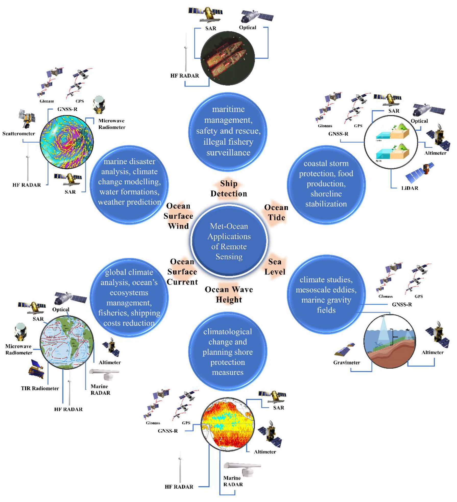
3. RS Applications in Ocean
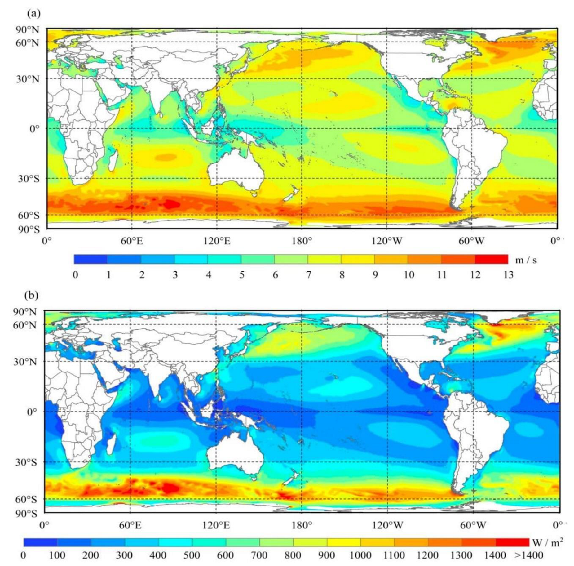
3.1. Ocean Surface Wind (OSW)
3.1.1. Microwave Radiometer
3.1.2. GNSS-R
3.1.3. SAR
3.1.4. Scatterometer
3.1.5. HF Radar
3.1.6. Summary and Future Direction
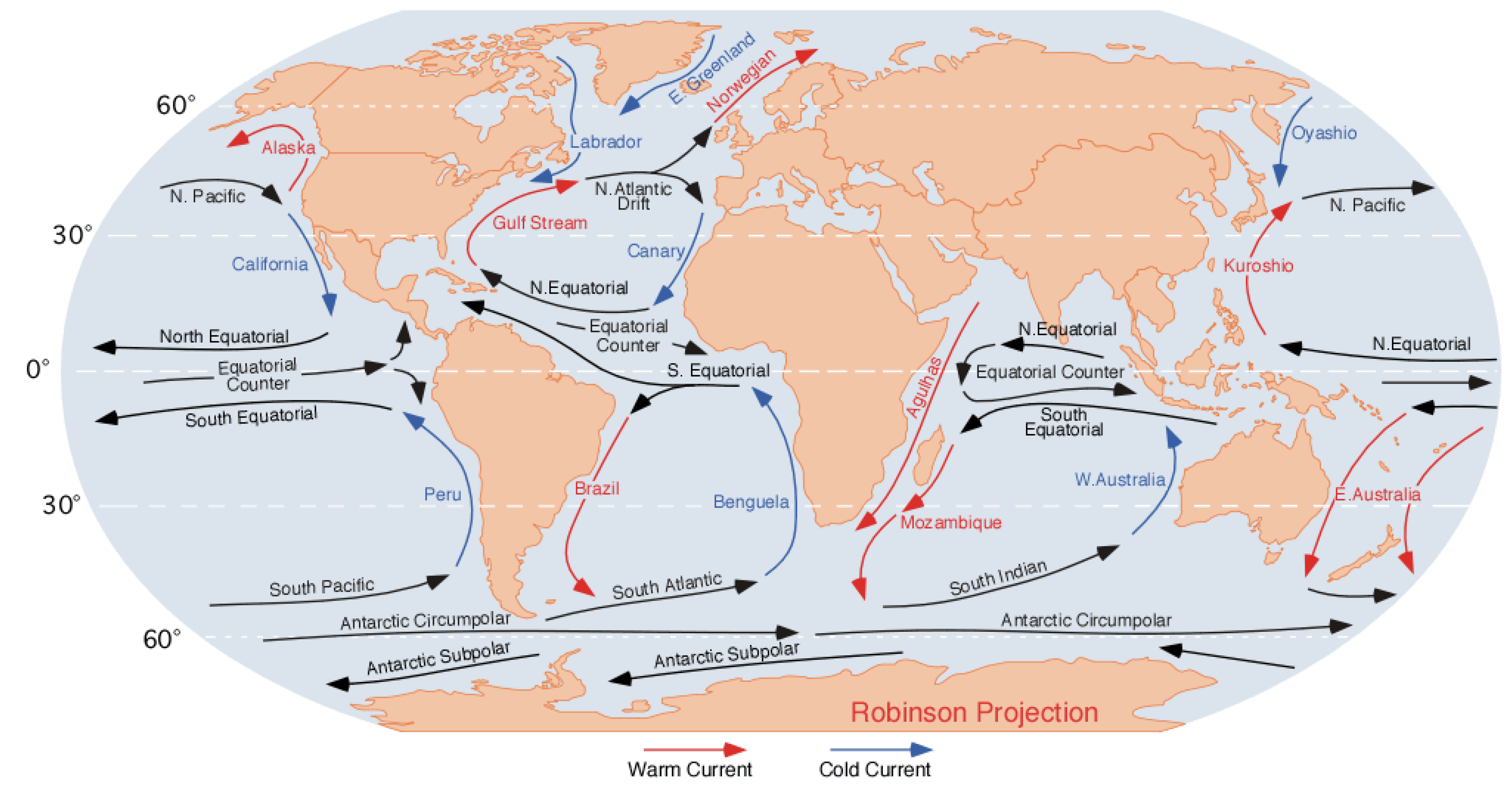
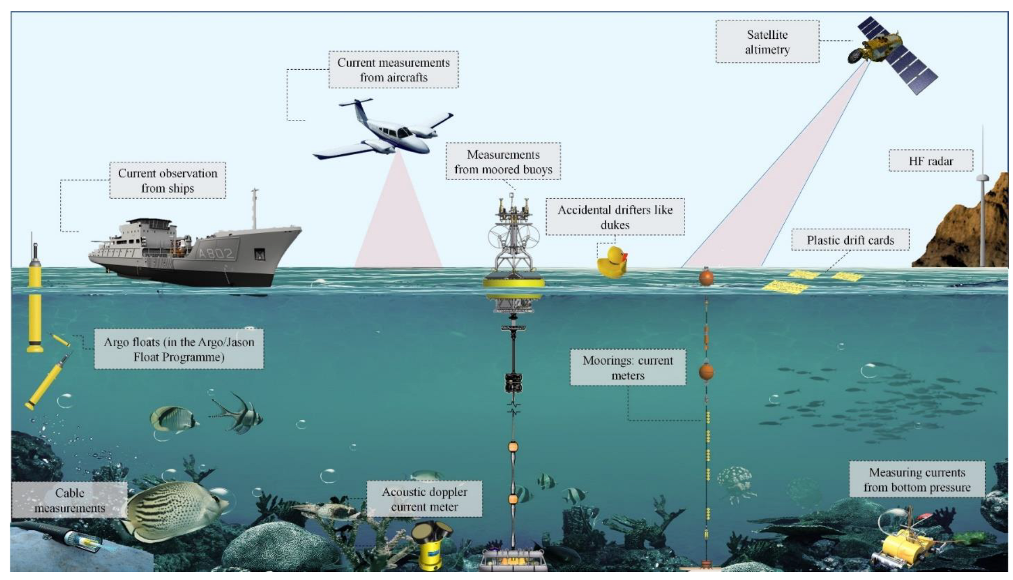
3.2. Ocean Surface Current (OSC)
3.2.1. Optical
3.2.2. TIR Radiometer
3.2.3. Microwave Radiometer
3.2.4. SAR
3.2.5. Altimeter
3.2.6. HF Radar
3.2.7. Marine Radar
3.2.8. Summary and Future Direction
3.3. Ocean Wave Height (OWH)
3.3.1. GNSS-R
3.3.2. SAR
3.3.3. Altimeter
3.3.4. HF Radar
3.3.5. Marine Radar
3.3.6. Summary and Future Direction
3.4. Sea Level (SL)
3.4.1. GNSS-R
3.4.2. Altimeter
3.4.3. Gravimeter
3.4.4. Summary and Future Direction
3.5. Ocean Tide (OT)
3.5.1. Optical
3.5.2. GNSS-R
3.5.3. SAR
3.5.4. Altimeter
3.5.5. LiDAR
3.5.6. Summary and Future Direction
3.6. Ship Detection (SD)
3.6.1. Optical
3.6.2. SAR
3.6.3. HF Radar
3.6.4. Summary and Future Direction
4. Conclusions
Author Contributions
Funding
Institutional Review Board Statement
Informed Consent Statement
Conflicts of Interest
Appendix A

| Acronym | Description |
|---|---|
| ADDMV | Allan Delay-Doppler Map Variance |
| AMSR | Advanced Microwave Scanning Radiometers |
| AOD | Atmospheric and Ocean De-aliasing |
| ASCAT | Advanced SCATterometer |
| AT-InSAR | Along-Track InSAR |
| AVHRR | Advanced Very High-Resolution Radiometer |
| AVISO | Archiving, Validation, and Interpretation of Satellite Oceanographic |
| AWEI | Automated Water Extraction Index |
| BT | Brightness Temperature |
| BTD | Brightness Temperature Difference |
| BTDSF | Difference between the temperature of sea surface and fog (BTSea surface − BTFog) |
| BTDTM | Brightness Temperature Difference recorded by the Thermal Infrared and Mid Infrared bands (i.e., BTTIR − BTMIR) |
| CAA | Civil Aviation Authority |
| CBERS | China–Brazil Earth Resources Satellite |
| CEOF | Complex Empirical Orthogonal Functions |
| CFAR | Constant FAR |
| CNN | Convolutional Neural Network |
| CONUS | Continental United States |
| CPI | Coherent Processing Interval |
| CSR | Center of Space Research |
| CTD | Coherent Target Decomposition |
| CVI | Composite Vulnerability Index |
| CYGNSS | Cyclone Global Navigation System Satellite |
| DCA | Doppler Centroid Anomaly |
| DDMA | Delay-Doppler Map Average |
| DDMs | Delay-Doppler Maps |
| DDMV | Delay-Doppler Map Variance |
| DEM | Digital Elevation Model |
| DFO | Department of Fisheries and Oceans |
| DInSAR | Differential InSAR |
| DL | Deep Learning |
| DSM | Digital Surface Model |
| ERS | European Remote Sensing |
| ESA | European Space Agency |
| ETS | Equitable Threat Score |
| EVI | Enhanced Vegetation Index |
| FAR | False Alarm Rate |
| GFZ | GeoForschungsZentrum |
| GNSS | Global Navigation Satellite Systems Reflectometry |
| GNSS-R | GNSS-Reflectometry |
| GNSS WG | GNSS Wave Glider |
| GOES-16 | Geostationary Operational Environmental Satellite system-16 |
| GLONASS | Global Navigation Satellite System |
| GMF | Geophysical Model Function |
| GMSL | Global Mean SL |
| GPS | Global Positioning System |
| GRACE | Gravity Recovery and Climate Experiment |
| GRD | Ground Range Detected |
| HF | High Frequency |
| HFHSSWR | HF Hybrid Sky–Surface Wave Radar |
| HRC | High-Resolution Current |
| ICOADS | International Comprehensive Ocean-Atmosphere Data Set |
| IFR | Instrument Flight Rules |
| InIRA | Imaging Radar Altimeter |
| InSAR | Interferometric SAR |
| INSAT | Indian National Satellite |
| IPCC | Intergovernmental Panel for Climate Change |
| IRNSS | Indian Regional Navigation Satellite System |
| IS | Intensity-Space |
| LBP | Local Binary Pattern |
| LEO | Low Earth Orbit |
| LES | Leading Edge Slope |
| LiDAR | Light Detection and Ranging |
| LIFR | Low Instrument Flight Rules |
| LMP | Local Multiple Pattern |
| LOS | Line of Sight |
| LSWI | Land Surface Water Index |
| LUT | Look-Up Table |
| MANMAR | Manual of Marine Weather Observations |
| MCC | Maximum Cross-Correlation |
| METAR | Meteorological Aerodrome Report |
| MetOp | Meteorological Operational satellite |
| MGDFs | Multiscale Gaussian Differential Features |
| MIR | Mid Infrared |
| ML | Machine Learning |
| MLE4 | Maximum Likelihood Estimator |
| MNDWI | Modified Normalized Difference Water Index |
| MSAVI | Modified Soil-Adjusted Vegetation Index |
| MV | Minimum Variance |
| MVFR | Marginal Visual Flight Rules |
| NAIP | National Agriculture Imagery Program |
| NASA | National Aeronautics and Space Administration |
| NDBC | National Data Buoy Center |
| NDVI | Normalized Difference Vegetation Index |
| NDWI | Normalized Difference Water Index |
| NIR | Near-Infrared |
| NL | Newfoundland and Labrador |
| NOAA | National Oceanic and Atmospheric Administration |
| NRCS | Normalized Radar Cross Section |
| NRT | Near Real-Time |
| NOAA | National Oceanic and Atmospheric Administration |
| NSF | Nighttime Sea Fog |
| NWP | Numerical Weather Prediction |
| OC | Ocean Color |
| OOS | Ocean Oil Spill |
| OS | Ocean Salinity |
| OSC | Ocean Surface Current |
| OSCAR | Ocean Surface Current Analysis Real-time |
| OSW | Ocean Surface Wind |
| OT | Ocean Tide |
| OTL | Ocean Tidal Load |
| OTV | Optimum Threshold Value |
| OWH | Ocean Wave Height |
| Probability Density Function | |
| PE | Polarimetric Entropy |
| PFT | Phase spectrum of Fourier Transform |
| POD | Probability Of Detection |
| PPP | Precise Point Positioning |
| PRF | Pulse Repetition Frequency |
| Probability of Nighttime Sea Fog for each pixel obtained from the spatial uniformity analysis | |
| PrNSF | Probability of Nighttime Sea Fog for each potential fog pixel |
| Probability of Nighttime Sea Fog for each potential fog pixel obtained from the BTDTM | |
| Probability of Nighttime Sea Fog for each potential fog pixel obtained from the BTDSF | |
| QuikSCAT | Quick SCATterometer |
| QZSS | Quasi-Zenith Satellite System |
| RCNN | Region-based CNN |
| RDM | Range-Doppler Map |
| RF | Random Forest |
| RIOPS | Regional Ice-Ocean Prediction System |
| RMSE | Root Mean Square Error |
| ROI | Regions of Interest |
| RPN | Region Proposal Network |
| RS | Remote Sensing |
| RSLR | Relative SL Rise |
| RT | Radiative Transfer |
| SAR | Synthetic Aperture Radar |
| SARAL | Satellite with ARgos and ALtiKa |
| SD | Ship Detection |
| SGR-ReSI | Space GNSS Receiver Remote Sensing Instrument |
| S-HOG | Ship Histogram of Oriented Gradient |
| SHP | Second-order Harmonic Peaks |
| SI | Sea Ice |
| SL | Sea Level |
| SLC | Single Look Complex |
| SMAP | Soil Moisture Active Passive |
| SMV | Significant Minimum Value |
| SMOS | Soil Moisture and Ocean Salinity |
| SNR | Signal-to-Noise Ratio |
| SONAR | Sound Navigation Ranging |
| SQG | Surface Quasi-Geostrophic |
| SST | Sea Surface Temperature |
| STAP | Space-Time Adaptive Processing |
| SVM | Support Vector Machine |
| SWIR | Shortwave Infrared |
| Std | Standard deviation |
| TDS-1 | TechDemoSat-1 |
| TES | Trailing Edge Slope |
| TIR | Thermal Infrared |
| UAV | Unmanned Aerial Vehicle |
| UK-DMC | United Kingdom Disaster Monitoring Constellation |
| UTC | Universal Time Coordinated |
| VHR | Very High Resolution |
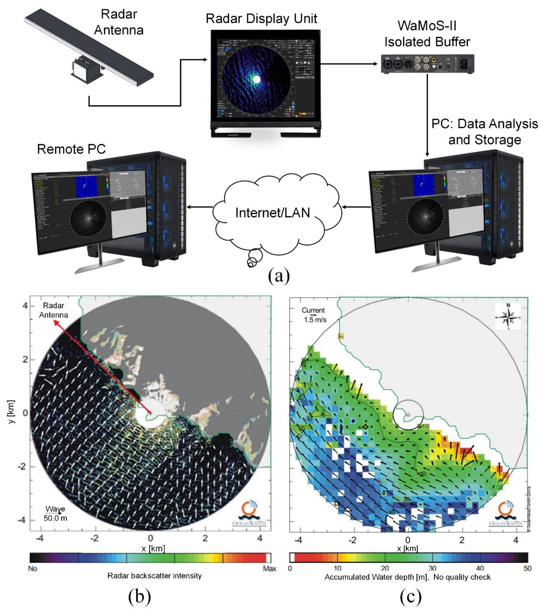
| WaMoS | Wave and Current Analysis and Wave Spectra |
References
- Devi, G.K.; Ganasri, B.P.; Dwarakish, G.S. Applications of Remote Sensing in Satellite Oceanography: A Review. Aquat. Procedia 2015, 4, 579–584. [Google Scholar] [CrossRef]
- Gholizadeh, M.H.; Melesse, A.M.; Reddi, L. A comprehensive review on water quality parameters estimation using remote sensing techniques. Sensors 2016, 16, 1298. [Google Scholar] [CrossRef]
- Bollmann, M. World ocean review: Living with the oceans. 2010. Available online: http://hdl.handle.net/1834/31403 (accessed on 12 December 2021).
- Amani, M.; Mahdavi, S.; Bullock, T.; Beale, S. Automatic nighttime sea fog detection using GOES-16 imagery. Atmos. Res. 2020, 238, 104712. [Google Scholar] [CrossRef]
- Honne Gowda, H.; Manikiam, B.; Jayaraman, V.; Chandrasekhar, M. Impact of satellite remote sensing on ocean modeling—An overview. Int. J. Remote Sens. 1993, 14, 3317–3331. [Google Scholar] [CrossRef]
- Minnett, P.; Alvera-Azcárate, A.; Chin, T.; Corlett, G.; Gentemann, C.; Karagali, I.; Li, X.; Marsouin, A.; Marullo, S.; Maturi, E. Half a century of satellite remote sensing of sea-surface temperature. Remote Sens. Environ. 2019, 233, 111366. [Google Scholar] [CrossRef]
- O’Carroll, A.G.; Armstrong, E.M.; Beggs, H.M.; Bouali, M.; Casey, K.S.; Corlett, G.K.; Dash, P.; Donlon, C.J.; Gentemann, C.L.; Høyer, J.L. Observational needs of sea surface temperature. Front. Mar. Sci. 2019, 6, 420. [Google Scholar] [CrossRef]
- Mahdavi, S.; Amani, M.; Bullock, T.; Beale, S. A probability-based daytime algorithm for sea fog detection using GOES-16 imagery. IEEE J. Sel. Top. Appl. Earth Obs. Remote Sens. 2020, 14, 1363–1373. [Google Scholar] [CrossRef]
- Kruk, R.; Fuller, M.C.; Komarov, A.S.; Isleifson, D.; Jeffrey, I. Proof of concept for sea ice stage of development classification using deep learning. Remote Sens. 2020, 12, 2486. [Google Scholar] [CrossRef]
- Chi, J.; Kim, H.-C. Prediction of arctic sea ice concentration using a fully data driven deep neural network. Remote Sens. 2017, 9, 1305. [Google Scholar] [CrossRef]
- Gao, Y.; Gao, F.; Dong, J.; Wang, S. Transferred deep learning for sea ice change detection from synthetic-aperture radar images. IEEE Geosci. Remote Sens. Lett. 2019, 16, 1655–1659. [Google Scholar] [CrossRef]
- Marmanis, D.; Datcu, M.; Esch, T.; Stilla, U. Deep learning earth observation classification using ImageNet pretrained networks. IEEE Geosci. Remote Sens. Lett. 2015, 13, 105–109. [Google Scholar] [CrossRef]
- Liu, H.; Guo, H.; Zhang, L. SVM-based sea ice classification using textural features and concentration from RADARSAT-2 dual-pol ScanSAR data. IEEE J. Sel. Top. Appl. Earth Obs. Remote Sens. 2014, 8, 1601–1613. [Google Scholar] [CrossRef]
- Su, H.; Wang, Y.; Xiao, J.; Yan, X.-H. Classification of MODIS images combining surface temperature and texture features using the Support Vector Machine method for estimation of the extent of sea ice in the frozen Bohai Bay, China. Int. J. Remote Sens. 2015, 36, 2734–2750. [Google Scholar] [CrossRef]
- Tempfli, K.; Huurneman, G.; Bakker, W.; Janssen, L.L.; Feringa, W.; Gieske, A.; Grabmaier, K.; Hecker, C.; Horn, J.; Kerle, N. Principles of Remote Sensing: An Introductory Textbook; International Institute for Geo-Information Science and Earth Observation: Enschede, The Netherlands, 2009. [Google Scholar]
- Raizer, V. Optical Remote Sensing of Ocean Hydrodynamics; CRC Press: Boca Raton, FL, USA, 2019. [Google Scholar]
- Parsons, S.; Amani, M.; Moghimi, A. Ocean colour mapping using remote sensing technology and an unsupervised machine learning algorithm. J. Ocean Technol. 2021, 16, 103–115. [Google Scholar]
- Sathyendranath, S. Remote Sensing of Ocean Colour in Coastal, and Other Optically-Complex, Waters; International Ocean Colour Coordinating Group (IOCCG): Dartmouth, NS, Canada, 2000. [Google Scholar]
- Embury, O.; Merchant, C.J.; Filipiak, M.J. A reprocessing for climate of sea surface temperature from the along-track scanning radiometers: Basis in radiative transfer. Remote Sens. Environ. 2012, 116, 32–46. [Google Scholar] [CrossRef]
- De Michele, M.; Leprince, S.; Thiébot, J.; Raucoules, D.; Binet, R. Direct measurement of ocean waves velocity field from a single SPOT-5 dataset. Remote Sens. Environ. 2012, 119, 266–271. [Google Scholar] [CrossRef]
- Amani, M.; Macdonald, C.; Mahdavi, S.; Gullage, M.; So, J. Aquatic vegetation mapping using machine learning algorithms and bathymetric lidar data: A case study from newfoundland, canada. J. Ocean Technol. 2021, 16, 76–94. [Google Scholar]
- Liu, S.; Chi, M.; Zou, Y.; Samat, A.; Benediktsson, J.A.; Plaza, A. Oil spill detection via multitemporal optical remote sensing images: A change detection perspective. IEEE Geosci. Remote Sens. Lett. 2017, 14, 324–328. [Google Scholar] [CrossRef]
- Seydi, S.T.; Hasanlou, M.; Amani, M.; Huang, W. Oil Spill Detection Based on Multiscale Multidimensional Residual CNN for Optical Remote Sensing Imagery. IEEE J. Sel. Top. Appl. Earth Obs. Remote Sens. 2021, 14, 10941–10952. [Google Scholar] [CrossRef]
- Bonnington, A.; Amani, M.; Ebrahimy, H. Oil Spill Detection Using Satellite Imagery. Adv. Environ. Eng. Res. 2021, 2, 1. [Google Scholar] [CrossRef]
- Kahle, A.B. A simple thermal model of the earth's surface for geologic mapping by remote sensing. J. Geophys. Res. 1977, 82, 1673–1680. [Google Scholar] [CrossRef]
- Klemas, V. Remote sensing techniques for studying coastal ecosystems: An overview. J. Coast. Res. 2011, 27, 2–17. [Google Scholar]
- Gentemann, C.L.; Donlon, C.J.; Stuart-Menteth, A.; Wentz, F.J. Diurnal signals in satellite sea surface temperature measurements. Geophys. Res. Lett. 2003, 30, 1140. [Google Scholar] [CrossRef]
- Lu, Y.; Zhan, W.; Hu, C. Detecting and quantifying oil slick thickness by thermal remote sensing: A ground-based experiment. Remote Sens. Environ. 2016, 181, 207–217. [Google Scholar] [CrossRef]
- Amlien, J. Remote sensing of snow with passive microwave radiometers—A review of current algorithms. Report 2008, 1019, 52. [Google Scholar]
- Woodhouse, I.H. Introduction to Microwave Remote Sensing; CRC Press: Boca Raton, FL, USA, 2017. [Google Scholar]
- Gaiser, P.W.; St Germain, K.M.; Twarog, E.M.; Poe, G.A.; Purdy, W.; Richardson, D.; Grossman, W.; Jones, W.L.; Spencer, D.; Golba, G. The WindSat spaceborne polarimetric microwave radiometer: Sensor description and early orbit performance. IEEE Trans. Geosci. Remote Sens. 2004, 42, 2347–2361. [Google Scholar] [CrossRef]
- Yueh, S.H.; Wilson, W.J.; Dinardo, S.J.; Hsiao, S.V. Polarimetric microwave wind radiometer model function and retrieval testing for WindSat. IEEE Trans. Geosci. Remote Sens. 2006, 44, 584–596. [Google Scholar] [CrossRef]
- Zavorotny, V.U.; Gleason, S.; Cardellach, E.; Camps, A. Tutorial on remote sensing using GNSS bistatic radar of opportunity. IEEE Geosci. Remote Sens. Mag. 2014, 2, 8–45. [Google Scholar] [CrossRef]
- Zavorotny, V.U.; Voronovich, A.G. Scattering of GPS signals from the ocean with wind remote sensing application. IEEE Trans. Geosci. Remote Sens. 2000, 38, 951–964. [Google Scholar] [CrossRef]
- Clarizia, M.P.; Ruf, C.S.; Jales, P.; Gommenginger, C. Spaceborne GNSS-R minimum variance wind speed estimator. IEEE Trans. Geosci. Remote Sens. 2014, 52, 6829–6843. [Google Scholar] [CrossRef]
- Garrison, J.L.; Komjathy, A.; Zavorotny, V.U.; Katzberg, S.J. Wind speed measurement using forward scattered GPS signals. IEEE Trans. Geosci. Remote Sens. 2002, 40, 50–65. [Google Scholar] [CrossRef]
- Gleason, S.; Hodgart, S.; Sun, Y.; Gommenginger, C.; Mackin, S.; Adjrad, M.; Unwin, M. Detection and processing of bistatically reflected GPS signals from low earth orbit for the purpose of ocean remote sensing. IEEE Trans. Geosci. Remote Sens. 2005, 43, 1229–1241. [Google Scholar] [CrossRef]
- Wiehl, M.; Legrésy, B. Potential of reflected GNSS signals for ice sheet remote sensing. Prog. Electromagn. Res. 2003, 40, 177–205. [Google Scholar] [CrossRef]
- Unwin, M.; Jales, P.; Tye, J.; Gommenginger, C.; Foti, G.; Rosello, J. Spaceborne GNSS-reflectometry on TechDemoSat-1: Early mission operations and exploitation. IEEE J. Sel. Top. Appl. Earth Obs. Remote Sens. 2016, 9, 4525–4539. [Google Scholar] [CrossRef]
- Ruf, C.S.; Chew, C.; Lang, T.; Morris, M.G.; Nave, K.; Ridley, A.; Balasubramaniam, R. A new paradigm in earth environmental monitoring with the cygnss small satellite constellation. Sci. Rep. 2018, 8, 8782. [Google Scholar] [CrossRef] [PubMed]
- Baghdadi, N.; Zribi, M. Microwave Remote Sensing of Land Surfaces: Techniques and Methods; Elsevier: Amsterdam, The Netherlands, 2016. [Google Scholar]
- Ulaby, F.; Long, D. Microwave Radar and Radiometric Remote Sensing; University of Michigan Press: Ann Arbor, MI, USA, 2014. [Google Scholar]
- Long, D.G. Polar applications of spaceborne scatterometers. IEEE J. Sel. Top. Appl. Earth Obs. Remote Sens. 2016, 10, 2307–2320. [Google Scholar] [CrossRef]
- Figa-Saldaña, J.; Wilson, J.J.; Attema, E.; Gelsthorpe, R.; Drinkwater, M.R.; Stoffelen, A. The advanced scatterometer (ASCAT) on the meteorological operational (MetOp) platform: A follow on for European wind scatterometers. Can. J. Remote Sens. 2002, 28, 404–412. [Google Scholar] [CrossRef]
- Dong, X.; Zhu, D.; Lin, W.; Liu, H.; Jiang, J. A Ku-band rotating fan-beam scatterometer: Design and performance simulations. In Proceedings of the 2010 IEEE International Geoscience and Remote Sensing Symposium, Honolulu, HI, USA, 25–30 July 2010; pp. 1081–1084. [Google Scholar]
- Lin, C.-C.; Rommen, B.; Wilson, J.J.W.; Impagnatiello, F.; Park, P.S. An analysis of a rotating, range-gated, fanbeam spaceborne scatterometer concept. IEEE Trans. Geosci. Remote Sens. 2000, 38, 2114–2121. [Google Scholar]
- Vu, P.L.; Frappart, F.; Darrozes, J.; Marieu, V.; Blarel, F.; Ramillien, G.; Bonnefond, P.; Birol, F. Multi-satellite altimeter validation along the French Atlantic coast in the southern bay of Biscay from ERS-2 to SARAL. Remote Sens. 2018, 10, 93. [Google Scholar] [CrossRef]
- Gómez-Enri, J.; Cipollini, P.; Gommenginger, C.; Martin-Puig, C.; Vignudelli, S.; Woodworth, P.; Benveniste, J.; Villares, P. COASTALT: Improving radar altimetry products in the oceanic coastal area. In Remote Sensing of the Ocean, Sea Ice, and Large Water Regions 2008; SPIE: Bellingham, WA, USA, 2008; pp. 132–141. [Google Scholar]
- Elachi, C.; Im, K.; Li, F.; Rodriguez, E. Global digital topography mapping with a synthetic aperture scanning radar altimeter. Int. J. Remote Sens. 1990, 11, 585–601. [Google Scholar] [CrossRef]
- Le Roy, Y.; Deschaux-Beaume, M.; Mavrocordatos, C.; Aguirre, M.; Heliere, F. SRAL SAR radar altimeter for sentinel-3 mission. In Proceedings of the 2007 IEEE International Geoscience and Remote Sensing Symposium, Barcelona, Spain, 23–28 July 2007; pp. 219–222. [Google Scholar]
- Wahle, C.M.; Dwight, D. Trueblood, National Ocean Service: What Is Eutrophication? Available online: https://oceanservice.noaa.gov/facts/eutrophication.html (accessed on 1 September 2021).
- Lowell, K.; Calder, B.; Lyons, A. Measuring shallow-water bathymetric signal strength in lidar point attribute data using machine learning. Int. J. Geogr. Inf. Sci. 2021, 35, 1592–1610. [Google Scholar] [CrossRef]
- Rogers, J.N.; Parrish, C.E.; Ward, L.G.; Burdick, D.M. Evaluation of field-measured vertical obscuration and full waveform lidar to assess salt marsh vegetation biophysical parameters. Remote Sens. Environ. 2015, 156, 264–275. [Google Scholar] [CrossRef]
- Massot-Campos, M.; Oliver-Codina, G. Optical sensors and methods for underwater 3D reconstruction. Sensors 2015, 15, 31525–31557. [Google Scholar] [CrossRef]
- Chen, J. Satellite gravimetry and mass transport in the earth system. Geod. Geodyn. 2019, 10, 402–415. [Google Scholar] [CrossRef]
- Besson, A. Weighing Earth, Tracking Water: Hydrological Applications of Data from GRACE Satellites. Doctoral Dissertation, Department of Geology and Geophysics, Yale University, New Haven, CT, USA, 2018. [Google Scholar]
- Ivins, E.R.; James, T.S.; Wahr, J.O.; Schrama, E.J.; Landerer, F.W.; Simon, K.M. Antarctic contribution to sea level rise observed by GRACE with improved GIA correction. J. Geophys. Res. Solid Earth 2013, 118, 3126–3141. [Google Scholar] [CrossRef]
- Peralta-Ferriz, C.; Morison, J.H.; Wallace, J.M.; Bonin, J.A.; Zhang, J. Arctic Ocean circulation patterns revealed by GRACE. J. Clim. 2014, 27, 1445–1468. [Google Scholar] [CrossRef]
- Johnson, G.C.; Chambers, D.P. Ocean bottom pressure seasonal cycles and decadal trends from GRACE Release-05: Ocean circulation implications. J. Geophys. Res. Ocean. 2013, 118, 4228–4240. [Google Scholar] [CrossRef]
- Schrama, E.J.; Wouters, B. Revisiting Greenland ice sheet mass loss observed by GRACE. J. Geophys. Res. Solid Earth 2011, 116. [Google Scholar] [CrossRef]
- Wouters, B.; Gardner, A.S.; Moholdt, G. Global glacier mass loss during the GRACE satellite mission (2002–2016). Front. Earth Sci. 2019, 7, 96. [Google Scholar] [CrossRef]
- Velicogna, I.; Wahr, J. Time-variable gravity observations of ice sheet mass balance: Precision and limitations of the GRACE satellite data. Geophys. Res. Lett. 2013, 40, 3055–3063. [Google Scholar] [CrossRef]
- Waite, A.D. Sonar for Practising Engineers; Wiley: Hoboken, NJ, USA, 2002. [Google Scholar]
- Hare, R.; Whittaker, C.; Clarke, J.; Beaudoin, J. Establishing a Multibeam Sonar Evaluation Test Bed near Sidney, British Columbia. In Proceedings of the 2012 Canadian Hydrographic Conference, Niagara Falls, Ontario, Canada, 15–17 May 2012. [Google Scholar]
- McConnell, J.A.; Weber, T.C.; Lauchle, G.C.; Gabrielson, T.B. Development of a high frequency underwater acoustic intensity probe. In Proceedings of the OCEANS'02 MTS/IEEE, Biloxi, MI, USA, 29-31 October 2002; pp. 1924–1929. [Google Scholar]
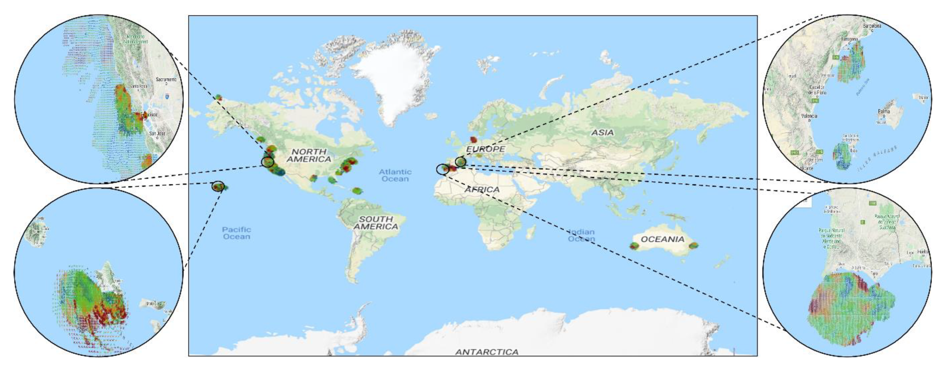
- Rubio, A.; Mader, J.; Corgnati, L.; Mantovani, C.; Griffa, A.; Novellino, A.; Quentin, C.; Wyatt, L.; Schulz-Stellenfleth, J.; Horstmann, J. HF radar activity in European coastal seas: Next steps toward a pan-European HF radar network. Front. Mar. Sci. 2017, 4, 8. [Google Scholar] [CrossRef]
- Paduan, J.D.; Washburn, L. High-frequency radar observations of ocean surface currents. Annu. Rev. Mar. Sci. 2013, 5, 115–136. [Google Scholar] [CrossRef] [PubMed]
- Lipa, B.; Barrick, D.; Alonso-Martirena, A.; Fernandes, M.; Ferrer, M.I.; Nyden, B. Brahan project high frequency radar ocean measurements: Currents, winds, waves and their interactions. Remote Sens. 2014, 6, 12094–12117. [Google Scholar] [CrossRef]
- Wyatt, L.; Thompson, S.; Burton, R. Evaluation of high frequency radar wave measurement. Coast. Eng. 1999, 37, 259–282. [Google Scholar] [CrossRef]
- Roarty, H.J.; Lemus, E.R.; Handel, E.; Glenn, S.M.; Barrick, D.E.; Isaacson, J. Performance evaluation of SeaSonde high-frequency radar for vessel detection. Mar. Technol. Soc. J. 2011, 45, 14–24. [Google Scholar] [CrossRef]
- Grilli, S.T.; Grosdidier, S.; Guérin, C.-A. Tsunami detection by high-frequency radar beyond the continental shelf. In Global Tsunami Science: Past and Future, Volume I; Springer: Berlin/Heidelberg, Germany, 2015; pp. 3895–3934. [Google Scholar]
- Chen, Z.; Zhang, B.; Kudryavtsev, V.; He, Y.; Chu, X. Estimation of sea surface current from X-band marine radar images by cross-spectrum analysis. Remote Sens. 2019, 11, 1031. [Google Scholar] [CrossRef]
- Hessner, K.; Reichert, K.; Borge, J.C.N.; Stevens, C.L.; Smith, M.J. High-resolution X-band radar measurements of currents, bathymetry and sea state in highly inhomogeneous coastal areas. Ocean Dyn. 2014, 64, 989–998. [Google Scholar] [CrossRef]
- Dankert, H.; Rosenthal, W. Ocean surface determination from X-band radar-image sequences. J. Geophys. Res. Ocean. 2004, 109, C04016. [Google Scholar] [CrossRef]
- Neill, S.P.; Hashemi, M.R. Fundamentals of Ocean Renewable Energy: Generating Electricity from the Sea; Academic Press: Cambridge, MA, USA, 2018. [Google Scholar]
- Chelton, D.B.; Schlax, M.G.; Freilich, M.H.; Milliff, R.F. Satellite measurements reveal persistent small-scale features in ocean winds. Science 2004, 303, 978–983. [Google Scholar] [CrossRef]
- Isaksen, L.; Stoffelen, A. ERS scatterometer wind data impact on ECMWF's tropical cyclone forecasts. IEEE Trans. Geosci. Remote Sens. 2000, 38, 1885–1892. [Google Scholar] [CrossRef]
- Rodríguez, E.; Bourassa, M.; Chelton, D.; Farrar, J.T.; Long, D.; Perkovic-Martin, D.; Samelson, R. The winds and currents mission concept. Front. Mar. Sci. 2019, 6, 438. [Google Scholar] [CrossRef]
- Villas Bôas, A.B.; Ardhuin, F.; Ayet, A.; Bourassa, M.A.; Brandt, P.; Chapron, B.; Cornuelle, B.D.; Farrar, J.T.; Fewings, M.R.; Fox-Kemper, B. Integrated observations of global surface winds, currents, and waves: Requirements and challenges for the next decade. Front. Mar. Sci. 2019, 6, 425. [Google Scholar] [CrossRef]
- Fang, H.; Xie, T.; Perrie, W.; Zhao, L.; Yang, J.; He, Y. Ocean wind and current retrievals based on satellite SAR measurements in conjunction with buoy and HF radar data. Remote Sens. 2017, 9, 1321. [Google Scholar] [CrossRef]
- Bourassa, M.; Stoffelen, A.; Bonekamp, H.; Chang, P.; Chelton, D.; Courtney, J.; Edson, R.; Figa, J.; He, Y.; Hersbach, H. Remotely sensed winds and wind stresses for marine forecasting and ocean modeling. Proc. Ocean. 2010, 9. [Google Scholar] [CrossRef]
- Hilburn, K.A.; Meissner, T.; Wentz, F.J.; Brown, S.T. Ocean vector winds from WindSat two-look polarimetric radiances. IEEE Trans. Geosci. Remote Sens. 2015, 54, 918–931. [Google Scholar] [CrossRef]
- Meissner, T.; Wentz, F.J. Wind-vector retrievals under rain with passive satellite microwave radiometers. IEEE Trans. Geosci. Remote Sens. 2009, 47, 3065–3083. [Google Scholar] [CrossRef]
- Ricciardulli, L.; Meissner, T.; Wentz, F. Towards a climate data record of satellite ocean vector winds. In Proceedings of the 2012 IEEE International Geoscience and Remote Sensing Symposium, Munich, Germany, 22–27 July 2012; pp. 2067–2069. [Google Scholar]
- Meissner, T.; Wentz, F. Ocean retrievals for WindSat: Radiative transfer model, algorithm, validation. In Proceedings of the OCEANS 2005 MTS/IEEE, Washington, DC, USA, 17–23 September 2005; pp. 130–133. [Google Scholar]
- Meissner, T.; Wentz, F.J.; Ricciardulli, L. The emission and scattering of L-band microwave radiation from rough ocean surfaces and wind speed measurements from the Aquarius sensor. J. Geophys. Res. Ocean. 2014, 119, 6499–6522. [Google Scholar] [CrossRef]
- Fore, A.G.; Yueh, S.H.; Tang, W.; Stiles, B.W.; Hayashi, A.K. Combined active/passive retrievals of ocean vector wind and sea surface salinity with SMAP. IEEE Trans. Geosci. Remote Sens. 2016, 54, 7396–7404. [Google Scholar] [CrossRef]
- Reul, N.; Tenerelli, J.; Chapron, B.; Vandemark, D.; Quilfen, Y.; Kerr, Y. SMOS satellite L-band radiometer: A new capability for ocean surface remote sensing in hurricanes. J. Geophys. Res. Ocean. 2012, 117, C02006. [Google Scholar] [CrossRef]
- Yin, X.; Wang, Z.; Song, Q.; Huang, Y.; Zhang, R. Estimate of ocean wind vectors inside tropical cyclones from polarimetric radiometer. IEEE J. Sel. Top. Appl. Earth Obs. Remote Sens. 2017, 10, 1701–1714. [Google Scholar] [CrossRef]
- Hwang, P.A.; Fan, Y. Low-frequency mean square slopes and dominant wave spectral properties: Toward tropical cyclone remote sensing. IEEE Trans. Geosci. Remote Sens. 2018, 56, 7359–7368. [Google Scholar] [CrossRef]
- Jales, P. Spaceborne Receiver Design for Scatterometric GNSS Reflectometry; University of Surrey: Guildford, UK, 2012. [Google Scholar]
- Foti, G.; Gommenginger, C.; Jales, P.; Unwin, M.; Shaw, A.; Robertson, C.; Rosello, J. Spaceborne GNSS reflectometry for ocean winds: First results from the UK TechDemoSat-1 mission. Geophys. Res. Lett. 2015, 42, 5435–5441. [Google Scholar] [CrossRef]
- Ruf, C.S.; Atlas, R.; Chang, P.S.; Clarizia, M.P.; Garrison, J.L.; Gleason, S.; Katzberg, S.J.; Jelenak, Z.; Johnson, J.T.; Majumdar, S.J. New ocean winds satellite mission to probe hurricanes and tropical convection. Bull. Am. Meteorol. Soc. 2016, 97, 385–395. [Google Scholar] [CrossRef]
- Bu, J.; Yu, K.; Zhu, Y.; Qian, N.; Chang, J. Developing and testing models for sea surface wind speed estimation with GNSS-R delay doppler maps and delay waveforms. Remote Sens. 2020, 12, 3760. [Google Scholar] [CrossRef]
- Ruf, C.S.; Balasubramaniam, R. Development of the CYGNSS geophysical model function for wind speed. IEEE J. Sel. Top. Appl. Earth Obs. Remote Sens. 2018, 12, 66–77. [Google Scholar] [CrossRef]
- Yang, X.; Li, X.; Pichel, W.G.; Li, Z. Comparison of ocean surface winds from ENVISAT ASAR, MetOp ASCAT scatterometer, buoy measurements, and NOGAPS model. IEEE Trans. Geosci. Remote Sens. 2011, 49, 4743–4750. [Google Scholar] [CrossRef]
- Beal, R.C. High Resolution wind Monitoring with Wide Swath SAR: A User's Guide; US Department of Commerce, National Oceanic and Atmospheric Administration: Silver Spring, MD, USA, 2005. [Google Scholar]
- Zhang, B.; Perrie, W. Cross-polarized synthetic aperture radar: A new potential measurement technique for hurricanes. Bull. Am. Meteorol. Soc. 2012, 93, 531–541. [Google Scholar] [CrossRef]
- Hwang, P.A.; Stoffelen, A.; van Zadelhoff, G.J.; Perrie, W.; Zhang, B.; Li, H.; Shen, H. Cross-polarization geophysical model function for C-band radar backscattering from the ocean surface and wind speed retrieval. J. Geophys. Res. Ocean. 2015, 120, 893–909. [Google Scholar] [CrossRef]
- Li, X.; Zhang, J.A.; Yang, X.; Pichel, W.G.; DeMaria, M.; Long, D.; Li, Z. Tropical cyclone morphology from spaceborne synthetic aperture radar. Bull. Am. Meteorol. Soc. 2013, 94, 215–230. [Google Scholar] [CrossRef]
- Wentz, F.J.; Ricciardulli, L.; Rodriguez, E.; Stiles, B.W.; Bourassa, M.A.; Long, D.G.; Hoffman, R.N.; Stoffelen, A.; Verhoef, A.; O'Neill, L.W. Evaluating and extending the ocean wind climate data record. IEEE J. Sel. Top. Appl. Earth Obs. Remote Sens. 2017, 10, 2165–2185. [Google Scholar] [CrossRef]
- Lin, C.-C.; Lengert, W.; Attema, E. Three generations of C-band wind scatterometer systems from ERS-1/2 to MetOp/ASCAT, and MetOp second generation. IEEE J. Sel. Top. Appl. Earth Obs. Remote Sens. 2016, 10, 2098–2122. [Google Scholar] [CrossRef]
- Guo, Q.; Xu, X.; Zhang, K.; Li, Z.; Huang, W.; Mansaray, L.R.; Liu, W.; Wang, X.; Gao, J.; Huang, J. Assessing global ocean wind energy resources using multiple satellite data. Remote Sens. 2018, 10, 100. [Google Scholar] [CrossRef]
- Sapp, J.W.; Alsweiss, S.O.; Jelenak, Z.; Chang, P.S.; Frasier, S.J.; Carswell, J. Airborne co-polarization and cross-polarization observations of the ocean-surface NRCS at C-band. IEEE Trans. Geosci. Remote Sens. 2016, 54, 5975–5992. [Google Scholar] [CrossRef]
- Stewart, R.H.; Barnum, J.R. Radio measurements of oceanic winds at long ranges: An evaluation. Radio Sci. 1975, 10, 853–857. [Google Scholar] [CrossRef]
- Maresca, J.; Barnum, J. Measurement of oceanic wind speed from HF sea scatter by skywave radar. IEEE Trans. Antennas Propag. 1977, 25, 132–136. [Google Scholar] [CrossRef]
- Barrick, D. Remote sensing of sea state by radar. In Proceedings of the Ocean 72-IEEE International Conference on Engineering in the Ocean Environment, Newport, RI, USA, 13–15 September 1972; pp. 186–192. [Google Scholar]
- Barrick, D.E.; Headrick, J.M.; Bogle, R.W.; Crombie, D.D. Sea backscatter at HF: Interpretation and utilization of the echo. Proc. IEEE 1974, 62, 673–680. [Google Scholar] [CrossRef]
- Ahearn, J.L.; Curley, S.R.; Headrick, J.M.; Trizna, D. Tests of remote skywave measurement of ocean surface conditions. Proc. IEEE 1974, 62, 681–687. [Google Scholar] [CrossRef]
- Dexter, P.; Theodoridis, S. Surface wind speed extraction from HF sky wave radar Doppler spectra. Radio Sci. 1982, 17, 643–652. [Google Scholar] [CrossRef]
- Huang, W.; Wu, S.; Gill, E.; Wen, B.; Hou, J. HF radar wave and wind measurement over the Eastern China Sea. IEEE Trans. Geosci. Remote Sens. 2002, 40, 1950–1955. [Google Scholar] [CrossRef]
- Klemas, V. Remote sensing of coastal and ocean currents: An overview. J. Coast. Res. 2012, 28, 576–586. [Google Scholar]
- Fu, L.-L.; Lee, T.; Liu, W.T.; Kwok, R. 50 years of satellite remote sensing of the ocean. Meteorol. Monogr. 2019, 59, 5.1–5.46. [Google Scholar] [CrossRef]
- Dohan, K.; Maximenko, N. Monitoring ocean currents with satellite sensors. Oceanography 2010, 23, 94–103. [Google Scholar] [CrossRef]
- Briney, A. How Ocean Currents Work. Available online: https://www.thoughtco.com/ocean-currents-1435343.2019 (accessed on 5 February 2021).
- Isern-Fontanet, J.; Ballabrera-Poy, J.; Turiel, A.; García-Ladona, E. Remote sensing of ocean surface currents: A review of what is being observed and what is being assimilated. Nonlinear Process. Geophys. 2017, 24, 613–643. [Google Scholar] [CrossRef]
- Gille, S.T.; Metzger, E.J.; Tokmakian, R. Seafloor Topography and Ocean Circulation; Naval Research Lab Stennis Space Center Ms Oceanography Div: Stennis Space Center, MS, USA, 2004. [Google Scholar]
- Dagestad, K.-F.; Röhrs, J. Prediction of ocean surface trajectories using satellite derived vs. modeled ocean currents modeled ocean currents. Remote Sens. Environ. 2019, 223, 130–142. [Google Scholar] [CrossRef]
- Ribbe, J.; Brieva, D. A western boundary current eddy characterisation study. Estuar. Coast. Shelf Sci. 2016, 183, 203–212. [Google Scholar] [CrossRef][Green Version]
- Hartmann, D.L. Global Physical Climatology, 2nd ed.; Elsevier: Amsterdam, The Netherlands.
- Lazier, J.R.; Wright, D.G. Annual velocity variations in the Labrador Current. J. Phys. Oceanogr. 1993, 23, 659–678. [Google Scholar] [CrossRef]
- Joseph, A. Measuring Ocean Currents: Tools, Technologies, and Data, 1st ed.; Elsevier: Waltham, MA, USA.
- Constantin, A. Frictional effects in wind-driven ocean currents. Geophys. Astrophys. Fluid Dyn. 2021, 115, 1–14. [Google Scholar] [CrossRef]
- Pinet, P.R. Invitation to Oceanography; Jones & Bartlett Learning: Burlington, MA, USA, 2019. [Google Scholar]
- Rahmstorf, S. Thermohaline circulation: The current climate. Nature 2003, 421, 699. [Google Scholar] [CrossRef]
- Schott, F.A.; Zantopp, R.; Stramma, L.; Dengler, M.; Fischer, J.; Wibaux, M. Circulation and deep-water export at the western exit of the subpolar North Atlantic. J. Phys. Oceanogr. 2004, 34, 817–843. [Google Scholar] [CrossRef]
- Yurovskaya, M.; Kudryavtsev, V.; Chapron, B.; Collard, F. Ocean surface current retrieval from space: The Sentinel-2 multispectral capabilities. Remote Sens. Environ. 2019, 234, 111468. [Google Scholar] [CrossRef]
- Sun, H.; Song, Q.; Shao, R.; Schlicke, T. Estimation of sea surface currents based on ocean colour remote-sensing image analysis. Int. J. Remote Sens. 2016, 37, 5105–5121. [Google Scholar] [CrossRef]
- Carvajal, G.K.; Eriksson, L.E.; Ulander, L.M.; Berg, A. Comparison between current fields detected with infrared radiometry and modeled currents around Sweden. In Proceedings of the 2013 IEEE International Geoscience and Remote Sensing Symposium-IGARSS, Melbourne, VIC, Australia, 21–26 July 2013; pp. 1270–1273. [Google Scholar]
- Heuzé, C.; Carvajal, G.K.; Eriksson, L.E.; Soja-Woźniak, M. Sea surface currents estimated from spaceborne infrared images validated against reanalysis data and drifters in the Mediterranean Sea. Remote Sens. 2017, 9, 422. [Google Scholar] [CrossRef]
- Crocker, R.I.; Matthews, D.K.; Emery, W.J.; Baldwin, D.G. Computing coastal ocean surface currents from infrared and ocean color satellite imagery. IEEE Trans. Geosci. Remote Sens. 2007, 45, 435–447. [Google Scholar] [CrossRef]
- González-Haro, C.; Isern-Fontanet, J. Ocean surface currents reconstruction at a global scale from microwave measurements. In Proceedings of the 2012 IEEE International Geoscience and Remote Sensing Symposium, Munich, Germany, 22–27 July 2012; pp. 3780–3783. [Google Scholar]
- González-Haro, C.; Isern-Fontanet, J. Assessment of ocean surface currents reconstruction at a global scale from the synergy between microwave and altimetric measurements. In Proceedings of the 2013 IEEE International Geoscience and Remote Sensing Symposium-IGARSS, Melbourne, VIC, Australia, 21–26 July 2013; pp. 2950–2953. [Google Scholar]
- González-Haro, C.; Isern-Fontanet, J. Global ocean current reconstruction from altimetric and microwave SST measurements. J. Geophys. Res. Ocean. 2014, 119, 3378–3391. [Google Scholar] [CrossRef]
- González-Haro, C.; Isern-Fontanet, J.; Tandeo, P.; Garello, R. Ocean surface currents reconstruction: Spectral characterization of the transfer function between SST and SSH. J. Geophys. Res. Ocean. 2020, 125, e2019JC015958. [Google Scholar] [CrossRef]
- Elyouncha, A. Sea Surface Current Measurements Using Along-Track Interferometric SAR. Ph.D. Thesis, Chalmers Tekniska Hogskola (Sweden), Göteborg, Sweden, 2018. [Google Scholar]
- Lyzenga, D.R.; Marmorino, G.O. Measurement of surface currents using sequential synthetic aperture radar images of slick patterns near the edge of the Gulf Stream. J. Geophys. Res. Ocean. 1998, 103, 18769–18777. [Google Scholar] [CrossRef]
- Hansen, M.W.; Collard, F.; Dagestad, K.-F.; Johannessen, J.A.; Fabry, P.; Chapron, B. Retrieval of sea surface range velocities from Envisat ASAR Doppler centroid measurements. IEEE Trans. Geosci. Remote Sens. 2011, 49, 3582–3592. [Google Scholar] [CrossRef]
- Marghany, M.; Hashim, M. Robust of doppler centroid for mapping sea surface current by using radar satellite data. Am. J. Eng. Appl. Sci. 2009, 2, 781–788. [Google Scholar] [CrossRef]
- Fu, B.; Huang, W.; Fan, K.; Gan, X.; Zhang, H.; Shi, A. Method for ocean surface currents measurement by SAR. In Remote Sensing and Modeling of the Atmosphere, Oceans, and Interactions II; SPIE: Bellingham, WA, USA, 2008; Volume 7148, pp. 56–61. [Google Scholar]
- Elyouncha, A.; Eriksson, L.E.; Johnsen, H.; Ulander, L.M. Using Sentinel-1 ocean data for mapping sea surface currents along the southern Norwegian coast. In Proceedings of the IGARSS 2019-2019 IEEE International Geoscience and Remote Sensing Symposium, Yokohama, Japan, 28 July–2 August 2019; pp. 8058–8061. [Google Scholar]
- Townsend, W.; McGoogan, J.; Walsh, E. Satellite radar altimeters-present and future oceanographic capabilities. In Oceanography from Space; Springer: Berlin/Heidelberg, Germany, 1981; pp. 625–636. [Google Scholar]
- Roarty, H.; Cook, T.; Hazard, L.; George, D.; Harlan, J.; Cosoli, S.; Wyatt, L.; Alvarez Fanjul, E.; Terrill, E.; Otero, M. The global high frequency radar network. Front. Mar. Sci. 2019, 6, 164. [Google Scholar] [CrossRef]
- Mantovani, C.; Corgnati, L.; Horstmann, J.; Rubio, A.; Reyes, E.; Quentin, C.; Cosoli, S.; Asensio, J.L.; Mader, J.; Griffa, A. Best practices on high frequency radar deployment and operation for ocean current measurement. Front. Mar. Sci. 2020, 7, 210. [Google Scholar] [CrossRef]
- Ji, Y.; Zhang, J.; Chu, X.; Wang, Y.; Yang, L. Ocean surface current measurement with high-frequency hybrid sky–surface wave radar. Remote Sens. Lett. 2017, 8, 617–626. [Google Scholar] [CrossRef]
- Kolukula, S.S.; Baduru, B.; Murty, P.; Kumar, J.P.; Rao, E.; Shenoi, S. Gaps Filling in HF Radar Sea Surface Current Data Using Complex Empirical Orthogonal Functions. Pure Appl. Geophys. 2020, 177, 5969–5992. [Google Scholar] [CrossRef]
- Huang, W.; Wu, X.; Lund, B.; El-Darymli, K. Advances in coastal HF and microwave (S-or X-band) radars. Int. J. Antennas Propag. 2017, 2017, 3089046. [Google Scholar] [CrossRef]
- Cheng, H.-Y.; Chien, H. Implementation of S-band marine radar for surface wave measurement under precipitation. Remote Sens. Environ. 2017, 188, 85–94. [Google Scholar] [CrossRef]
- Neill, S.P.; Hashemi, M.R. Ocean modelling for resource characterization. Fundam. Ocean Renew. Energy 2018, 193–235. [Google Scholar] [CrossRef]
- Horstmann, J.; Carrasco, R.; Seemann, J.; Cysewski, M. Surface current measurements using marine radars. In Proceedings of the 2015 IEEE/OES Eleveth Current, Waves and Turbulence Measurement (CWTM), St. Petersburg, FL, USA, 2-6 March 2015; pp. 1–3. [Google Scholar]
- Hongo, C.; Kawamata, H.; Goto, K. Catastrophic impact of typhoon waves on coral communities in the Ryukyu Islands under global warming. J. Geophys. Res. Biogeosci. 2012, 117, G02029. [Google Scholar] [CrossRef]
- Osadchiev, A. Small mountainous rivers generate high-frequency internal waves in coastal ocean. Sci. Rep. 2018, 8, 16609. [Google Scholar] [CrossRef]
- Dobson, E.; Monaldo, F.; Goldhirsh, J.; Wilkerson, J. Validation of Geosat altimeter-derived wind speeds and significant wave heights using buoy data. J. Geophys. Res. Ocean. 1987, 92, 10719–10731. [Google Scholar] [CrossRef]
- Chowdhary, J.; Zhai, P.-W.; Boss, E.; Dierssen, H.; Frouin, R.; Ibrahim, A.; Lee, Z.; Remer, L.A.; Twardowski, M.; Xu, F. Modeling atmosphere-ocean radiative transfer: A PACE mission perspective. Front. Earth Sci. 2019, 7, 100. [Google Scholar] [CrossRef]
- Gabarró, C.; Font, J.; Camps, A.; Vall-llossera, M.; Julià, A. A new empirical model of sea surface microwave emissivity for salinity remote sensing. Geophys. Res. Lett. 2004, 31, L01309. [Google Scholar] [CrossRef]
- James, S.C.; Zhang, Y.; O'Donncha, F. A machine learning framework to forecast wave conditions. Coast. Eng. 2018, 137, 1–10. [Google Scholar] [CrossRef]
- Shao, Q.; Li, W.; Han, G.; Hou, G.; Liu, S.; Gong, Y.; Qu, P. A Deep Learning Model for Forecasting Sea Surface Height Anomalies and Temperatures in the South China Sea. J. Geophys. Res. Ocean. 2021, 126, e2021JC017515. [Google Scholar] [CrossRef]
- Liu, J.; Jin, B.; Wang, L.; Xu, L. Sea surface height prediction with deep learning based on attention mechanism. IEEE Geosci. Remote Sens. Lett. 2020, 19, 1501605. [Google Scholar] [CrossRef]
- Rius, A.; Cardellach, E.; Martin-Neira, M. Altimetric analysis of the sea-surface GPS-reflected signals. IEEE Trans. Geosci. Remote Sens. 2010, 48, 2119–2127. [Google Scholar] [CrossRef]
- Chen, F.; Liu, L.; Guo, F. Sea surface height estimation with multi-GNSS and wavelet de-noising. Sci. Rep. 2019, 9, 15181. [Google Scholar] [CrossRef]
- Larson, K.M.; Löfgren, J.S.; Haas, R. Coastal sea level measurements using a single geodetic GPS receiver. Adv. Space Res. 2013, 51, 1301–1310. [Google Scholar] [CrossRef]
- Santamaría-Gómez, A.; Watson, C.; Gravelle, M.; King, M.; Wöppelmann, G. Levelling co-located GNSS and tide gauge stations using GNSS reflectometry. J. Geod. 2015, 89, 241–258. [Google Scholar] [CrossRef]
- Penna, N.T.; Morales Maqueda, M.A.; Martin, I.; Guo, J.; Foden, P.R. Sea surface height measurement using a GNSS Wave Glider. Geophys. Res. Lett. 2018, 45, 5609–5616. [Google Scholar] [CrossRef]
- Zhang, B.; Perrie, W.; He, Y. Remote sensing of ocean waves by along-track interferometric synthetic aperture radar. J. Geophys. Res. Ocean. 2009, 114, C10015. [Google Scholar] [CrossRef]
- Lin, B.; Shao, W.; Li, X.; Li, H.; Du, X.; Ji, Q.; Cai, L. Development and validation of an ocean wave retrieval algorithm for VV-polarization Sentinel-1 SAR data. Acta Oceanol. Sin. 2017, 36, 95–101. [Google Scholar] [CrossRef]
- Shao, W.; Hu, Y.; Yang, J.; Nunziata, F.; Sun, J.; Li, H.; Zuo, J. An empirical algorithm to retrieve significant wave height from Sentinel-1 synthetic aperture radar imagery collected under cyclonic conditions. Remote Sens. 2018, 10, 1367. [Google Scholar] [CrossRef]
- Alpers, W.R.; Ross, D.B.; Rufenach, C.L. On the detectability of ocean surface waves by real and synthetic aperture radar. J. Geophys. Res. Ocean. 1981, 86, 6481–6498. [Google Scholar] [CrossRef]
- Mastenbroek, C.; De Valk, C. A semiparametric algorithm to retrieve ocean wave spectra from synthetic aperture radar. J. Geophys. Res. Ocean. 2000, 105, 3497–3516. [Google Scholar] [CrossRef]
- Jian, S.; Changlong, G. Parameterized first-guess spectrum method for retrieving directional spectrum of swell-dominated waves and huge waves from SAR images. Chin. J. Oceanol. Limnol. 2006, 24, 12–20. [Google Scholar] [CrossRef]
- Schulz-Stellenfleth, J.; Lehner, S.; Hoja, D. A parametric scheme for the retrieval of two-dimensional ocean wave spectra from synthetic aperture radar look cross spectra. J. Geophys. Res. Ocean. 2005, 110, C05004. [Google Scholar] [CrossRef]
- Wang, H.; Wang, J.; Yang, J.; Ren, L.; Zhu, J.; Yuan, X.; Xie, C. Empirical algorithm for significant wave height retrieval from wave mode data provided by the Chinese satellite Gaofen-3. Remote Sens. 2018, 10, 363. [Google Scholar] [CrossRef]
- Schulz-Stellenfleth, J.; König, T.; Lehner, S. An empirical approach for the retrieval of integral ocean wave parameters from synthetic aperture radar data. J. Geophys. Res. Ocean. 2007, 112, C03019. [Google Scholar] [CrossRef]
- Li, X.-M.; Lehner, S.; Bruns, T. Ocean wave integral parameter measurements using Envisat ASAR wave mode data. IEEE Trans. Geosci. Remote Sens. 2010, 49, 155–174. [Google Scholar] [CrossRef]
- Stopa, J.E.; Mouche, A. Significant wave heights from S entinel-1 SAR: Validation and applications. J. Geophys. Res. Ocean. 2017, 122, 1827–1848. [Google Scholar] [CrossRef]
- Bruck, M.; Lehner, S. TerraSAR-X/TanDEM-X sea state measurements using the XWAVE algorithm. Int. J. Remote Sens. 2015, 36, 3890–3912. [Google Scholar] [CrossRef]
- Shao, W.; Zhang, Z.; Li, X.; Li, H. Ocean wave parameters retrieval from Sentinel-1 SAR imagery. Remote Sens. 2016, 8, 707. [Google Scholar] [CrossRef]
- Tarpanelli, A.; Benveniste, J. On the potential of altimetry and optical sensors for monitoring and forecasting river discharge and extreme flood events. In Extreme Hydroclimatic Events and Multivariate Hazards in a Changing Environment; Elsevier: Amsterdam, The Netherlands, 2019; pp. 267–287. [Google Scholar]
- Wang, J.; Aouf, L.; Jia, Y.; Zhang, Y. Validation and calibration of significant wave height and wind speed retrievals from HY2B altimeter based on Deep Learning. Remote Sens. 2020, 12, 2858. [Google Scholar] [CrossRef]
- Peng, F.; Deng, X. Validation of improved significant wave heights from the Brown-Peaky (BP) retracker along the east coast of Australia. Remote Sens. 2018, 10, 1072. [Google Scholar] [CrossRef]
- Barrick, D.E. Extraction of wave parameters from measured HF radar sea-echo Doppler spectra. Radio Sci. 1977, 12, 415–424. [Google Scholar] [CrossRef]
- Gurgel, K.-W.; Essen, H.-H.; Schlick, T. An empirical method to derive ocean waves from second-order Bragg scattering: Prospects and limitations. IEEE J. Ocean. Eng. 2006, 31, 804–811. [Google Scholar] [CrossRef]
- Tian, Z.; Tian, Y.; Wen, B.; Wang, S.; Zhao, J.; Huang, W.; Gill, E.W. Wave-height mapping from second-order harmonic peaks of wide-beam HF radar backscatter spectra. IEEE Trans. Geosci. Remote Sens. 2019, 58, 925–937. [Google Scholar] [CrossRef]
- Zhou, H.; Wen, B. Radio frequency interference suppression in small-aperture high-frequency radars. IEEE Geosci. Remote Sens. Lett. 2012, 9, 788–792. [Google Scholar] [CrossRef]
- Nazari, M.E.; Huang, W.; Zhao, C. Dense Radio Frequency Interference Cancellation by CEMD and Temporal Windowing Processing for HFSW Radar. In Proceedings of the OCEANS 2019-Marseille, Marseille, France, 17–20 June 2019; pp. 1–4. [Google Scholar]
- Nazari, M.E.; Huang, W.; Zhao, C. Radio frequency interference suppression for HF surface wave radar using CEMD and temporal windowing methods. IEEE Geosci. Remote Sens. Lett. 2019, 17, 212–216. [Google Scholar] [CrossRef]
- Zhou, H.; Wen, B. Wave height extraction from the first-order Bragg peaks in high-frequency radars. IEEE Geosci. Remote Sens. Lett. 2015, 12, 2296–2300. [Google Scholar] [CrossRef]
- Tian, Y.; Wen, B.; Zhou, H.; Wang, C.; Yang, J.; Huang, W. Wave height estimation from first-order backscatter of a dual-frequency high frequency radar. Remote Sens. 2017, 9, 1186. [Google Scholar] [CrossRef]
- Huang, W.; Liu, X.; Gill, E.W. Ocean wind and wave measurements using X-band marine radar: A comprehensive review. Remote Sens. 2017, 9, 1261. [Google Scholar] [CrossRef]
- Hessner, K.G.; Nieto-Borge, J.C.; Bell, P.S. Nautical radar measurements in Europe: Applications of WaMoS II as a sensor for sea state, current and bathymetry. In Remote Sensing of the European Seas; Springer: Berlin/Heidelberg, Germany, 2008; pp. 435–446. [Google Scholar]
- Vicen-Bueno, R.; Lido-Muela, C.; Nieto-Borge, J.C. Estimate of significant wave height from non-coherent marine radar images by multilayer perceptrons. EURASIP J. Adv. Signal Process. 2012, 2012, 84. [Google Scholar] [CrossRef]
- Chuang, L.Z.-H.; Wu, L.-C.; Doong, D.-J.; Kao, C.C. Two-dimensional continuous wavelet transform of simulated spatial images of waves on a slowly varying topography. Ocean Eng. 2008, 35, 1039–1051. [Google Scholar] [CrossRef]
- Ma, K.; Wu, X.; Yue, X.; Wang, L.; Liu, J. Array beamforming algorithm for estimating waves and currents from marine X-band radar image sequences. IEEE Trans. Geosci. Remote Sens. 2016, 55, 1262–1272. [Google Scholar] [CrossRef]
- Henschel, M.; Buckley, J.; Dobson, F. Estimates of wave height from low incidence angle sea clutter. Proceedings of the Fourth International Workshop on Wave Hindcasting and Forecasting; Federal Panel on Energy R&D, 1995. Available online: https://www.google.com.hk/url?sa=t&rct=j&q=&esrc=s&source=web&cd=&cad=rja&uact=8&ved=2ahUKEwjqjtDjrf36AhXH9zgGHeDdC2EQFnoECAgQAQ&url=https%3A%2F%2Fwaves-vagues.dfo-mpo.gc.ca%2FLibrary%2F223549.pdf&usg=AOvVaw393d9o6YAGnWxW6h4MfTPN (accessed on 4 September 2022).
- Gangeskar, R. Wave height derived by texture analysis of X-band radar sea surface images. In Proceedings of the IGARSS 2000. IEEE 2000 International Geoscience and Remote Sensing Symposium. Taking the Pulse of the Planet: The Role of Remote Sensing in Managing the Environment. Proceedings (Cat. No. 00CH37120), Honolulu, HI, USA, 24-28 July 2000; pp. 2952–2959. [Google Scholar]
- Dankert, H.; Horstmann, J.; Rosenthal, W. Wind-and wave-field measurements using marine X-band radar-image sequences. IEEE J. Ocean. Eng. 2005, 30, 534–542. [Google Scholar] [CrossRef]
- Liu, X.; Huang, W.; Gill, E.W. Comparison of wave height measurement algorithms for ship-borne X-band nautical radar. Can. J. Remote Sens. 2016, 42, 343–353. [Google Scholar] [CrossRef]
- Gangeskar, R. An algorithm for estimation of wave height from shadowing in X-band radar sea surface images. IEEE Trans. Geosci. Remote Sens. 2013, 52, 3373–3381. [Google Scholar] [CrossRef]
- Salcedo-Sanz, S.; Borge, J.N.; Carro-Calvo, L.; Cuadra, L.; Hessner, K.; Alexandre, E. Significant wave height estimation using SVR algorithms and shadowing information from simulated and real measured X-band radar images of the sea surface. Ocean Eng. 2015, 101, 244–253. [Google Scholar] [CrossRef]
- Chen, Z.; He, Y.; Zhang, B.; Qiu, Z.; Yin, B. A new algorithm to retrieve wave parameters from marine X-band radar image sequences. IEEE Trans. Geosci. Remote Sens. 2013, 52, 4083–4091. [Google Scholar] [CrossRef]
- Liu, X.; Huang, W.; Gill, E.W. Estimation of significant wave height from X-band marine radar images based on ensemble empirical mode decomposition. IEEE Geosci. Remote Sens. Lett. 2017, 14, 1740–1744. [Google Scholar] [CrossRef]
- Trizna, D.B. Coherent marine radar measurements of ocean wave frequency spectra and near surface currents. In Proceedings of the OCEANS 2016-Shanghai, Shanghai, China, 10-13 April 2016; pp. 1–5. [Google Scholar]
- Hwang, P.A.; Sletten, M.A.; Toporkov, J.V. A note on Doppler processing of coherent radar backscatter from the water surface: With application to ocean surface wave measurements. J. Geophys. Res. Ocean. 2010, 115, C03026. [Google Scholar] [CrossRef]
- Carrasco, R.; Streßer, M.; Horstmann, J. A simple method for retrieving significant wave height from Dopplerized X-band radar. Ocean Sci. 2017, 13, 95–103. [Google Scholar] [CrossRef]
- Carrasco, R.; Horstmann, J.; Seemann, J. Significant wave height measured by coherent X-band radar. IEEE Trans. Geosci. Remote Sens. 2017, 55, 5355–5365. [Google Scholar] [CrossRef]
- Seiz, G.; Foppa, N. National climate observing system of switzerland (GCOS Switzerland). Adv. Sci. Res. 2011, 6, 95–102. [Google Scholar] [CrossRef]
- Shum, C.; Ries, J.; Tapley, B. The accuracy and applications of satellite altimetry. Geophys. J. Int. 1995, 121, 321–336. [Google Scholar] [CrossRef]
- Wang, G.; Su, J.; Chu, P.C. Mesoscale eddies in the South China Sea observed with altimeter data. Geophys. Res. Lett. 2003, 30, 2121. [Google Scholar] [CrossRef]
- Jiang, X.; Song, Q. Satellite microwave measurements of the global oceans and future missions. Keji Daobao/Sci. Technol. Rev. 2010, 28, 105–111. [Google Scholar]
- Oppenheimer, M.; Glavovic, B.C.; Hinkel, J.; van de Wal, R.; Magnan, A.K.; Abd-Elgawad, A.; Cai, R.M.; Cifuentes-Jara, R.M.; DeConto, T.; Ghosh, J.; et al. 2019: Sea Level Rise and Implications for Low-Lying Islands, Coasts and Communities Supplementary Material. In IPCC Special Report on the Ocean and Cryosphere in a Changing Climate; Pörtner, H.-O., Roberts, D.C., Masson-Delmotte, V., Zhai, P., Tignor, M., Poloczanska, E., Mintenbeck, K., Alegría, M., Nicolai, A., Okem, J., et al., Eds.; Available online: https://www.ipcc.ch/site/assets/uploads/sites/3/2019/11/SROCC_Ch04-SM_FINAL.pdf (accessed on 5 September 2022).
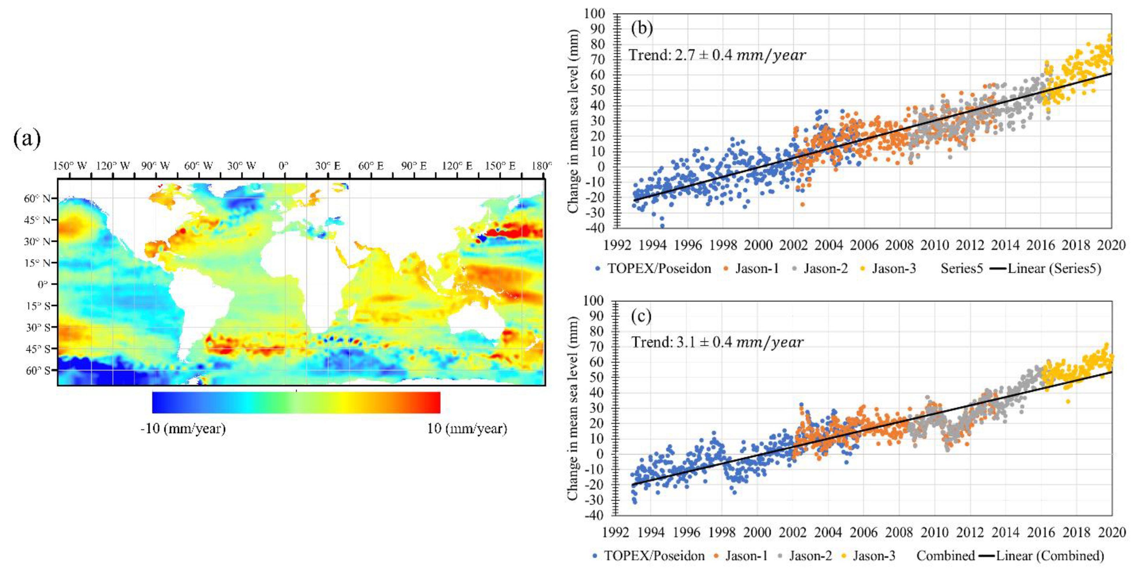
- Climate.gov, Climate Change: Global Sea Level. Available online: https://www.climate.gov/news-features/understanding-climate/climate-change-global-sea-level (accessed on 23 May 2022).
- NOAA/NESDIS/STAR, Laboratory for Satellite Altimetry/Sea Level Rise. Available online: https://www.star.nesdis.noaa.gov/socd/lsa/SeaLevelRise/ (accessed on 27 July 2022).
- Qiu, H.; Jin, S. Global Mean Sea Surface Height Estimated from Spaceborne Cyclone-GNSS Reflectometry. Remote Sens. 2020, 12, 356. [Google Scholar] [CrossRef]
- Church, J.A.; White, N.J. Sea-level rise from the late 19th to the early 21st century. Surv. Geophys. 2011, 32, 585–602. [Google Scholar] [CrossRef]
- Palmer, M.D.; Harris, G.R.; Gregory, J.M. Extending CMIP5 projections of global mean temperature change and sea level rise due to thermal expansion using a physically-based emulator. Environ. Res. Lett. 2018, 13, 084003. [Google Scholar] [CrossRef]
- Frederikse, T.; Landerer, F.; Caron, L.; Adhikari, S.; Parkes, D.; Humphrey, V.W.; Dangendorf, S.; Hogarth, P.; Zanna, L.; Cheng, L. The causes of sea-level rise since 1900. Nature 2020, 584, 393–397. [Google Scholar] [CrossRef]
- Feng, W.; Shum, C.; Zhong, M.; Pan, Y. Groundwater storage changes in China from satellite gravity: An overview. Remote Sens. 2018, 10, 674. [Google Scholar] [CrossRef]
- Tuck, M.E.; Kench, P.S.; Ford, M.R.; Masselink, G. Physical modelling of the response of reef islands to sea-level rise. Geology 2019, 47, 803–806. [Google Scholar] [CrossRef]
- Reineman, D.R.; Thomas, L.N.; Caldwell, M.R. Using local knowledge to project sea level rise impacts on wave resources in California. Ocean Coast. Manag. 2017, 138, 181–191. [Google Scholar] [CrossRef]
- Sahin, O.; Stewart, R.A.; Faivre, G.; Ware, D.; Tomlinson, R.; Mackey, B. Spatial Bayesian Network for predicting sea level rise induced coastal erosion in a small Pacific Island. J. Environ. Manag. 2019, 238, 341–351. [Google Scholar] [CrossRef]
- Meyer, R.; Engesgaard, P.; Sonnenborg, T.O. Origin and dynamics of saltwater intrusion in a regional aquifer: Combining 3-D saltwater modeling with geophysical and geochemical data. Water Resour. Res. 2019, 55, 1792–1813. [Google Scholar] [CrossRef]
- Varela, M.R.; Patrício, A.R.; Anderson, K.; Broderick, A.C.; DeBell, L.; Hawkes, L.A.; Tilley, D.; Snape, R.T.; Westoby, M.J.; Godley, B.J. Assessing climate change associated sea-level rise impacts on sea turtle nesting beaches using drones, photogrammetry and a novel GPS system. Glob. Change Biol. 2019, 25, 753–762. [Google Scholar] [CrossRef]
- Kheir, A.M.; El Baroudy, A.; Aiad, M.A.; Zoghdan, M.G.; Abd El-Aziz, M.A.; Ali, M.G.; Fullen, M.A. Impacts of rising temperature, carbon dioxide concentration and sea level on wheat production in North Nile delta. Sci. Total Environ. 2019, 651, 3161–3173. [Google Scholar] [CrossRef]
- Carvalho, K.; Wang, S. Characterizing the Indian Ocean sea level changes and potential coastal flooding impacts under global warming. J. Hydrol. 2019, 569, 373–386. [Google Scholar] [CrossRef]
- Christodoulou, A.; Christidis, P.; Demirel, H. Sea-level rise in ports: A wider focus on impacts. Marit. Econ. Logist. 2019, 21, 482–496. [Google Scholar] [CrossRef]
- Parker, V.T.; Boyer, K.E. Sea-level rise and climate change impacts on an urbanized Pacific Coast estuary. Wetlands 2019, 39, 1219–1232. [Google Scholar] [CrossRef]
- Oral, N. International Law as an Adaptation Measure to Sea-level Rise and Its Impacts on Islands and Offshore Features. Int. J. Mar. Coast. Law 2019, 34, 415–439. [Google Scholar] [CrossRef]
- Lafta, A.A.; Altaei, S.A.; Al-Hashimi, N.H. Impacts of potential sea-level rise on tidal dynamics in Khor Abdullah and Khor Al-Zubair, northwest of Arabian Gulf. Earth Syst. Environ. 2020, 4, 93–105. [Google Scholar] [CrossRef]
- Dill, R.; Dobslaw, H. Seasonal variations in global mean sea level and consequences on the excitation of length-of-day changes. Geophys. J. Int. 2019, 218, 801–816. [Google Scholar] [CrossRef]
- Lowe, S.T.; Zuffada, C.; Chao, Y.; Kroger, P.; Young, L.E.; LaBrecque, J.L. 5-cm-Precision aircraft ocean altimetry using GPS reflections. Geophys. Res. Lett. 2002, 29, 13-11–13-14. [Google Scholar] [CrossRef]
- Jeon, T.; Seo, K.-W.; Youm, K.; Chen, J.; Wilson, C.R. Global sea level change signatures observed by GRACE satellite gravimetry. Sci. Rep. 2018, 8, 13519. [Google Scholar] [CrossRef]
- Quartly, G.D.; Rinne, E.; Passaro, M.; Andersen, O.B.; Dinardo, S.; Fleury, S.; Guillot, A.; Hendricks, S.; Kurekin, A.A.; Müller, F.L. Retrieving sea level and freeboard in the Arctic: A review of current radar altimetry methodologies and future perspectives. Remote Sens. 2019, 11, 881. [Google Scholar] [CrossRef]
- Balogun, A.-L.; Adebisi, N. Sea level prediction using ARIMA, SVR and LSTM neural network: Assessing the impact of ensemble Ocean-Atmospheric processes on models’ accuracy. Geomat. Nat. Hazards Risk 2021, 12, 653–674. [Google Scholar] [CrossRef]
- Nieves, V.; Radin, C.; Camps-Valls, G. Predicting regional coastal sea level changes with machine learning. Sci. Rep. 2021, 11, 7650. [Google Scholar] [CrossRef]
- Chupin, C.; Ballu, V.; Testut, L.; Tranchant, Y.-T.; Calzas, M.; Poirier, E.; Coulombier, T.; Laurain, O.; Bonnefond, P.; Project, T.F. Mapping sea surface height using new concepts of kinematic GNSS instruments. Remote Sens. 2020, 12, 2656. [Google Scholar] [CrossRef]
- Clarizia, M.P.; Ruf, C.; Cipollini, P.; Zuffada, C. First spaceborne observation of sea surface height using GPS-Reflectometry. Geophys. Res. Lett. 2016, 43, 767–774. [Google Scholar] [CrossRef]
- Gleason, S.; Gebre-Egziabher, D.; Egziabher, D.G. GNSS Applications and Methods; Artech House: Norwood, MA, USA, 2009. [Google Scholar]
- Martin-Neira, M. A passive reflectometry and interferometry system (PARIS): Application to ocean altimetry. ESA J. 1993, 17, 331–355. [Google Scholar]
- Hajj, G.A.; Zuffada, C. Theoretical description of a bistatic system for ocean altimetry using the GPS signal. Radio Sci. 2003, 38, 10-11–10-19. [Google Scholar] [CrossRef]
- Cardellach, E.; Rius, A.; Martín-Neira, M.; Fabra, F.; Nogues-Correig, O.; Ribó, S.; Kainulainen, J.; Camps, A.; D'Addio, S. Consolidating the precision of interferometric GNSS-R ocean altimetry using airborne experimental data. IEEE Trans. Geosci. Remote Sens. 2013, 52, 4992–5004. [Google Scholar] [CrossRef]
- Camps, A.; Park, H.; i Domènech, E.V.; Pascual, D.; Martin, F.; Rius, A.; Ribo, S.; Benito, J.; Andrés-Beivide, A.; Saameno, P. Optimization and performance analysis of interferometric GNSS-R altimeters: Application to the PARIS IoD mission. IEEE J. Sel. Top. Appl. Earth Obs. Remote Sens. 2014, 7, 1436–1451. [Google Scholar] [CrossRef]
- Wang, Q.; Zheng, W.; Wu, F.; Xu, A.; Zhu, H.; Liu, Z. A New GNSS-R Altimetry Algorithm Based on Machine Learning Fusion Model and Feature Optimization to Improve the Precision of Sea Surface Height Retrieval. Front. Earth Sci. 2021, 758. [Google Scholar] [CrossRef]
- Taqi, A.M.; Al-Subhi, A.M.; Alsaafani, M.A.; Abdulla, C.P. Improving sea level anomaly precision from satellite altimetry using parameter correction in the Red Sea. Remote Sens. 2020, 12, 764. [Google Scholar] [CrossRef]
- Fernandes, M.J.; Lázaro, C.; Ablain, M.; Pires, N. Improved wet path delays for all ESA and reference altimetric missions. Remote Sens. Environ. 2015, 169, 50–74. [Google Scholar] [CrossRef]
- Carrere, L.; Faugère, Y.; Ablain, M. Major improvement of altimetry sea level estimations using pressure-derived corrections based on ERA-Interim atmospheric reanalysis. Ocean Sci. 2016, 12, 825–842. [Google Scholar] [CrossRef]
- Carrere, L.; Lyard, F.; Cancet, M.; Guillot, A. FES 2014, a new tidal model on the global ocean with enhanced accuracy in shallow seas and in the Arctic region. In Proceedings of the EGU General Assembly 2015, Vienna, Austria, 12–17 April 2015. [Google Scholar]
- Passaro, M.; Nadzir, Z.A.; Quartly, G.D. Improving the precision of sea level data from satellite altimetry with high-frequency and regional sea state bias corrections. Remote Sens. Environ. 2018, 218, 245–254. [Google Scholar] [CrossRef]
- Ren, L.; Yang, J.; Dong, X.; Zhang, Y.; Jia, Y. Preliminary Evaluation and Correction of Sea Surface Height from Chinese Tiangong-2 Interferometric Imaging Radar Altimeter. Remote Sens. 2020, 12, 2496. [Google Scholar] [CrossRef]
- Dinardo, S.; Fenoglio-Marc, L.; Buchhaupt, C.; Becker, M.; Scharroo, R.; Fernandes, M.J.; Benveniste, J. Coastal sar and plrm altimetry in german bight and west baltic sea. Adv. Space Res. 2018, 62, 1371–1404. [Google Scholar] [CrossRef]
- Mullick, M.R.A.; Tanim, A.; Islam, S.S. Coastal vulnerability analysis of Bangladesh coast using fuzzy logic based geospatial techniques. Ocean Coast. Manag. 2019, 174, 154–169. [Google Scholar] [CrossRef]
- Yang, L.; Jin, T.; Gao, X.; Wen, H.; Schöne, T.; Xiao, M.; Huang, H. Sea Level Fusion of Satellite Altimetry and Tide Gauge Data by Deep Learning in the Mediterranean Sea. Remote Sens. 2021, 13, 908. [Google Scholar] [CrossRef]
- Bindoff, N.L.; Willebrand, J.; Artale, V.; Cazenave, A.; Gregory, J.; Gulev, S.; Hanawa, K.; Le Quéré, C.; Levitus, S.; Nojiri, Y.; et al. 007: Observations: Oceanic Climate Change and Sea Level. In Climate Change 2007: The Physical Science Basis. Contribution of Working Group I to the Fourth Assessment Report of the Intergovernmental Panel on Climate Change; Solomon, S.D., Qin, M., Manning, Z., Chen, M., Marquis, K.B., Averyt, M.T., Miller, H.L., Eds.; Cambridge University Press: Cambridge, UK; New York, NY, USA.
- Chen, J.; Tapley, B.; Seo, K.W.; Wilson, C.; Ries, J. Improved quantification of global mean ocean mass change using GRACE satellite gravimetry measurements. Geophys. Res. Lett. 2019, 46, 13984–13991. [Google Scholar] [CrossRef]
- Cazenave, A.; Dominh, K.; Guinehut, S.; Berthier, E.; Llovel, W.; Ramillien, G.; Ablain, M.; Larnicol, G. Sea level budget over 2003–2008: A reevaluation from GRACE space gravimetry, satellite altimetry and Argo. Glob. Planet. Change 2009, 65, 83–88. [Google Scholar] [CrossRef]
- Elsaka, B.; Radwan, A.M.; Rashwan, M. Evaluation of Nile Delta-Mediterranean Sea conjunction using GPS, satellite-based gravity and altimetry datasets. J. Geosci. Environ. Prot. 2020, 8, 33. [Google Scholar] [CrossRef]
- Drogoudi, P.D.; Tsipouridis, C.; Michailidis, Z. Physical and chemical characteristics of pomegranates. HortScience 2005, 40, 1200–1203. [Google Scholar] [CrossRef]
- Roadmap, T. Welcome to Tides and Water Levels. Available online: https://oceanservice.noaa.gov/education/tutorial_tides/welcome.htmldate (accessed on 5 September 2022).
- Taylor, G.I.I. Tidal friction in the Irish Sea. Philos. Trans. R. Soc. London. Ser. A Contain. Pap. A Math. Or Phys. Character 1920, 220, 1–33. [Google Scholar]
- Jeffreys, H., VIII. Tidal friction in shallow seas. Philos. Trans. R. Soc. London. Ser. A Contain. Pap. A Math. Or Phys. Character 1921, 221, 239–264. [Google Scholar]
- Cartwright, D.E.; Ray, R. Oceanic tides from Geosat altimetry. J. Geophys. Res. Ocean. 1990, 95, 3069–3090. [Google Scholar] [CrossRef]
- Egbert, G.; Ray, R. Significant dissipation of tidal energy in the deep ocean inferred from satellite altimeter data. Nature 2000, 405, 775–778. [Google Scholar] [CrossRef] [PubMed]
- Tierney, C.C.; Kantha, L.H.; Born, G.H. Shallow and deep water global ocean tides from altimetry and numerical modeling. J. Geophys. Res. Ocean. 2000, 105, 11259–11277. [Google Scholar] [CrossRef]
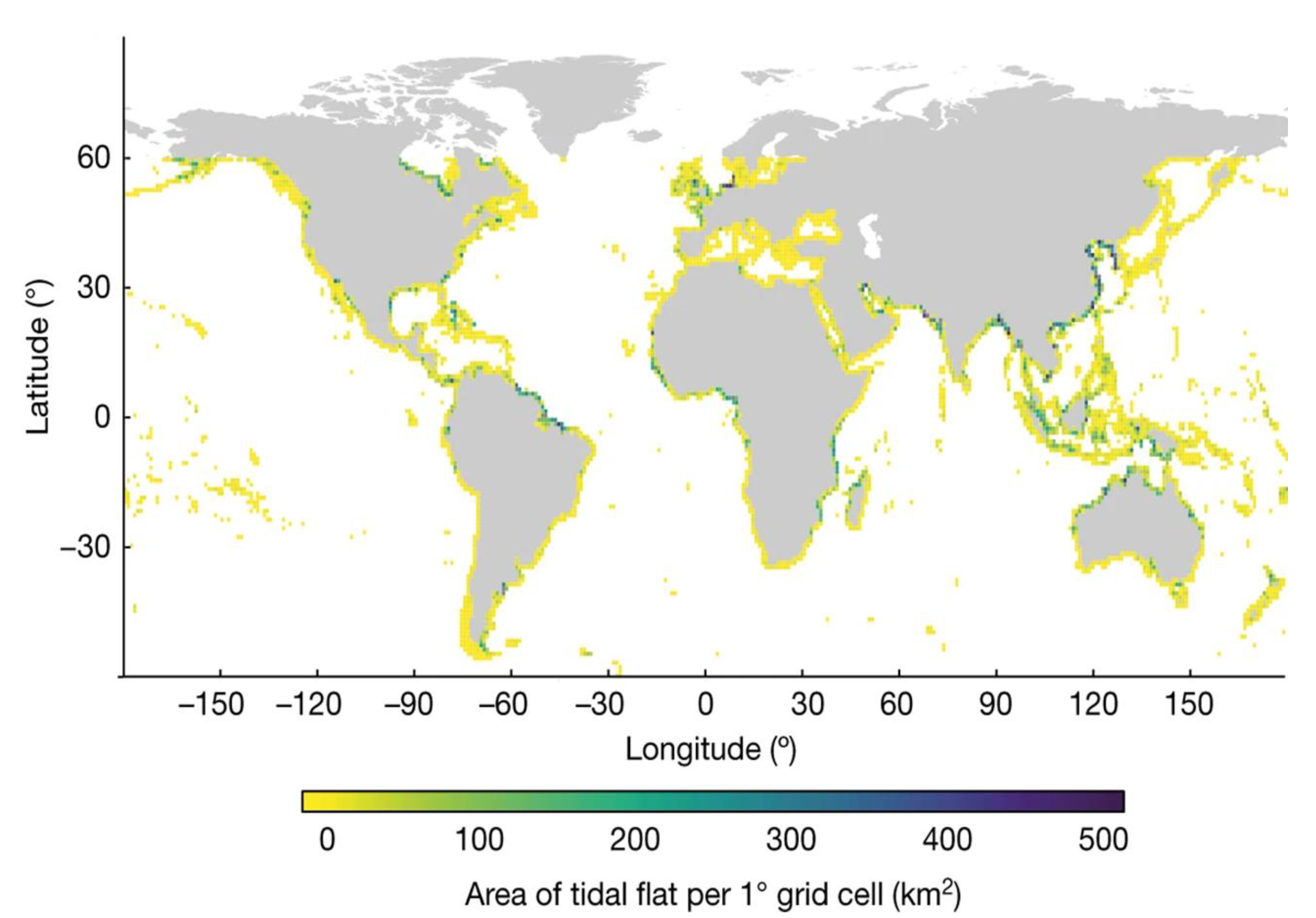
- Ryu, J.-H.; Choi, J.-K.; Lee, Y.-K. Potential of remote sensing in management of tidal flats: A case study of thematic mapping in the Korean tidal flats. Ocean Coast. Manag. 2014, 102, 458–470. [Google Scholar] [CrossRef]
- Murray, N.J.; Phinn, S.R.; DeWitt, M.; Ferrari, R.; Johnston, R.; Lyons, M.B.; Clinton, N.; Thau, D.; Fuller, R.A. The global distribution and trajectory of tidal flats. Nature 2019, 565, 222–225. [Google Scholar] [CrossRef] [PubMed]
- Gade, M.; Alpers, W.; Melsheimer, C.; Tanck, G. Classification of sediments on exposed tidal flats in the German Bight using multi-frequency radar data. Remote Sens. Environ. 2008, 112, 1603–1613. [Google Scholar] [CrossRef]
- Lee, J.K.; Lee, I.; Kim, J.O. Analysis on tidal channels based on UAV photogrammetry: Focused on the west coast, South Korea case analysis. J. Coast. Res. 2017, 199–203. [Google Scholar] [CrossRef]
- Mason, D.C.; Scott, T.R.; Wang, H.-J. Extraction of tidal channel networks from airborne scanning laser altimetry. ISPRS J. Photogramm. Remote Sens. 2006, 61, 67–83. [Google Scholar] [CrossRef]
- Letcher, T.M. Future Energy: Improved, Sustainable and Clean Options for Our Planet; Elsevier: The Netherlands, 2008. [Google Scholar]
- Du, T.; Tseng, Y.H.; Yan, X.H. Impacts of tidal currents and Kuroshio intrusion on the generation of nonlinear internal waves in Luzon Strait. J. Geophys. Res. Ocean. 2008, 113, C08015. [Google Scholar] [CrossRef]
- Ferreira, R.M.; Estefen, S.F.; Romeiser, R. Under what conditions sar along-track interferometry is suitable for assessment of tidal energy resource. IEEE J. Sel. Top. Appl. Earth Obs. Remote Sens. 2016, 9, 5011–5022. [Google Scholar] [CrossRef]
- Tsai, C.-H.; Doong, D.-J.; Chen, Y.-C.; Yen, C.-W.; Maa, M.J. Tidal stream characteristics on the coast of Cape Fuguei in northwestern Taiwan for a potential power generation site. Int. J. Mar. Energy 2016, 13, 193–205. [Google Scholar] [CrossRef]
- Schubert, G. (Ed.) Treatise on Geophysics, 2nd ed.; Elsevier: Amsterdam, The Netherlands, 2015. [Google Scholar]
- Kelly, M.; Tuxen, K. Remote sensing support for tidal wetland vegetation research and management. In Remote Sensing and Geospatial Technologies for Coastal Ecosystem Assessment and Management; Springer: Berlin/Heidelberg, Germany, 2009; pp. 341–363. [Google Scholar]
- Magolan, J.L.; Halls, J.N. A multi-decadal investigation of tidal creek wetland changes, water level rise, and ghost forests. Remote Sens. 2020, 12, 1141. [Google Scholar] [CrossRef]
- Slatton, K.C.; Crawford, M.M.; Chang, L.-D. Modeling temporal variations in multipolarized radar scattering from intertidal coastal wetlands. ISPRS J. Photogramm. Remote Sens. 2008, 63, 559–577. [Google Scholar] [CrossRef]
- Wang, C.; Liu, H.-Y.; Zhang, Y.; Li, Y.-f. Classification of land-cover types in muddy tidal flat wetlands using remote sensing data. J. Appl. Remote Sens. 2014, 7, 073457. [Google Scholar] [CrossRef]
- Whyte, A.; Ferentinos, K.P.; Petropoulos, G.P. A new synergistic approach for monitoring wetlands using Sentinels-1 and 2 data with object-based machine learning algorithms. Environ. Model. Softw. 2018, 104, 40–54. [Google Scholar] [CrossRef]
- Ryu, J.-H.; Won, J.-S.; Min, K.D. Waterline extraction from Landsat TM data in a tidal flat: A case study in Gomso Bay, Korea. Remote Sens. Environ. 2002, 83, 442–456. [Google Scholar] [CrossRef]
- Murray, N.J.; Phinn, S.R.; Clemens, R.S.; Roelfsema, C.M.; Fuller, R.A. Continental scale mapping of tidal flats across East Asia using the Landsat archive. Remote Sens. 2012, 4, 3417–3426. [Google Scholar] [CrossRef]
- Zhao, Y.; Liu, Q.; Huang, R.; Pan, H.; Xu, M. Recent Evolution of Coastal Tidal Flats and the Impacts of Intensified Human Activities in the Modern Radial Sand Ridges, East China. Int. J. Environ. Res. Public Health 2020, 17, 3191. [Google Scholar] [CrossRef] [PubMed]
- Angeles, G.R.; Perillo, G.M.; Piccolo, M.C.; Pierini, J.O. Fractal analysis of tidal channels in the Bahıa Blanca Estuary (Argentina). Geomorphology 2004, 57, 263–274. [Google Scholar] [CrossRef]
- Mahdavi, S.; Salehi, B.; Granger, J.; Amani, M.; Brisco, B.; Huang, W. Remote sensing for wetland classification: A comprehensive review. GIScience Remote Sens. 2018, 55, 623–658. [Google Scholar] [CrossRef]
- Amani, M.; Mahdavi, S.; Berard, O. Supervised wetland classification using high spatial resolution optical, SAR, and LiDAR imagery. J. Appl. Remote Sens. 2020, 14, 024502. [Google Scholar] [CrossRef]
- Mahdavi, S.; Salehi, B.; Amani, M.; Granger, J.; Brisco, B.; Huang, W. A dynamic classification scheme for mapping spectrally similar classes: Application to wetland classification. Int. J. Appl. Earth Obs. Geoinf. 2019, 83, 101914. [Google Scholar] [CrossRef]
- Kleinherenbrink, M.; Riva, R.; Frederikse, T. A comparison of methods to estimate vertical land motion trends from GNSS and altimetry at tide gauge stations. Ocean Sci. 2018, 14, 187–204. [Google Scholar] [CrossRef]
- Takiguchi, H.; Otsubo, T.; Fukuda, Y. Reduction of influences of the earth's Surface Fluid Loads on GPS Site Coordinate Time Series and Global Satellite Laser Ranging Analysis. 2006. Available online: https://openrepository.aut.ac.nz/handle/10292/3985 (accessed on 12 January 2022).
- Zhou, M.; Liu, X.; Guo, J.; Jin, X.; Chang, X. Ocean Tide Loading Displacement Parameters Estimated From GNSS-Derived Coordinate Time Series Considering the Effect of Mass Loading in Hong Kong. IEEE J. Sel. Top. Appl. Earth Obs. Remote Sens. 2020, 13, 6064–6076. [Google Scholar] [CrossRef]
- MirMazloumi, S.M.; Sahebi, M.R. Assessment of different backscattering models for bare soil surface parameters estimation from SAR data in band C, L and P. Eur. J. Remote Sens. 2016, 49, 261–278. [Google Scholar] [CrossRef]
- Heygster, G.; Dannenberg, J.; Notholt, J. Topographic mapping of the German tidal flats analyzing SAR images with the waterline method. IEEE Trans. Geosci. Remote Sens. 2009, 48, 1019–1030. [Google Scholar] [CrossRef]
- Lamont-Smith, T.; Dovey, P. The effect of tidal currents on radar backscatter from the sea around Portland Bill. Int. J. Remote Sens. 2005, 26, 2061–2079. [Google Scholar] [CrossRef]
- Ren, Y.; Li, X.-M.; Gao, G.; Busche, T.E. Derivation of sea surface tidal current from spaceborne SAR constellation data. IEEE Trans. Geosci. Remote Sens. 2017, 55, 3236–3247. [Google Scholar] [CrossRef]
- DiCaprio, C.J.; Simons, M. Importance of ocean tidal load corrections for differential InSAR. Geophys. Res. Lett. 2008, 35, L22309. [Google Scholar] [CrossRef]
- Peng, W.; Wang, Q.; Cao, Y. Analysis of ocean tide loading in differential InSAR measurements. Remote Sens. 2017, 9, 101. [Google Scholar] [CrossRef]
- Wdowinski, S.; Hong, S.-H.; Mulcan, A.; Brisco, B. Remote-sensing monitoring of tide propagation through coastal wetlands. Oceanography 2013, 26, 64–69. [Google Scholar] [CrossRef]
- Amani, M.; Salehi, B.; Mahdavi, S.; Brisco, B.; Shehata, M. A Multiple Classifier System to improve mapping complex land covers: A case study of wetland classification using SAR data in Newfoundland, Canada. Int. J. Remote Sens. 2018, 39, 7370–7383. [Google Scholar] [CrossRef]
- Mahdavi, S.; Salehi, B.; Amani, M.; Granger, J.E.; Brisco, B.; Huang, W.; Hanson, A. Object-based classification of wetlands in Newfoundland and Labrador using multi-temporal PolSAR data. Can. J. Remote Sens. 2017, 43, 432–450. [Google Scholar] [CrossRef]
- Egbert, G.D.; Ray, R.D. Tidal prediction. J. Mar. Res. 2017, 75, 189–237. [Google Scholar] [CrossRef]
- Ray, R.D.; Zaron, E.D. Non-stationary internal tides observed with satellite altimetry. Geophys. Res. Lett. 2011, 38, L17609. [Google Scholar] [CrossRef]
- Chen, L. Detection of shoreline changes for tideland areas using multi-temporal satellite images. Int. J. Remote Sens. 1998, 19, 3383–3397. [Google Scholar] [CrossRef]
- Tseng, K.-H.; Kuo, C.-Y.; Lin, T.-H.; Huang, Z.-C.; Lin, Y.-C.; Liao, W.-H.; Chen, C.-F. Reconstruction of time-varying tidal flat topography using optical remote sensing imageries. ISPRS J. Photogramm. Remote Sens. 2017, 131, 92–103. [Google Scholar] [CrossRef]
- Mason, D.; Scott, T.; Dance, S. Remote sensing of intertidal morphological change in Morecambe Bay, UK, between 1991 and 2007. Estuar. Coast. Shelf Sci. 2010, 87, 487–496. [Google Scholar] [CrossRef]
- Passaro, M.; Fenoglio-Marc, L.; Cipollini, P. Validation of significant wave height from improved satellite altimetry in the German Bight. IEEE Trans. Geosci. Remote Sens. 2014, 53, 2146–2156. [Google Scholar] [CrossRef]
- Yu, H.; Li, J.; Wu, K.; Wang, Z.; Yu, H.; Zhang, S.; Hou, Y.; Kelly, R.M. A global high-resolution ocean wave model improved by assimilating the satellite altimeter significant wave height. Int. J. Appl. Earth Obs. Geoinf. 2018, 70, 43–50. [Google Scholar] [CrossRef]
- Lee, M.; Oh, N.; Kim, G.; Kang, J. Modeling tidal current around mokpo, the south western coastal zone of korea. In Proceedings of the the 7th International Conference on Asian and Pacific Coasts, Bali, Indonesia, 24–26 September 2013; pp. 521–526. [Google Scholar]
- Green, J.; Pugh, D.T. Bardsey–an island in a strong tidal stream: Underestimating coastal tides due to unresolved topography. Ocean Sci. 2020, 16, 1337–1345. [Google Scholar] [CrossRef]
- Niedermeier, A.; Hoja, D.; Lehner, S. Topography and morphodynamics in the German Bight using SAR and optical remote sensing data. Ocean Dyn. 2005, 55, 100–109. [Google Scholar] [CrossRef]
- Anthony, E.J.; Dolique, F.; Gardel, A.; Gratiot, N.; Proisy, C.; Polidori, L. Nearshore intertidal topography and topographic-forcing mechanisms of an Amazon-derived mud bank in French Guiana. Cont. Shelf Res. 2008, 28, 813–822. [Google Scholar] [CrossRef]
- Ryu, J.-H.; Kim, C.-H.; Lee, Y.-K.; Won, J.-S.; Chun, S.-S.; Lee, S. Detecting the intertidal morphologic change using satellite data. Estuar. Coast. Shelf Sci. 2008, 78, 623–632. [Google Scholar] [CrossRef]
- Lee, Y.-K.; Ryu, J.-H.; Choi, J.-K.; Soh, J.-G.; Eom, J.-A.; Won, J.-S. A study of decadal sedimentation trend changes by waterline comparisons within the Ganghwa tidal flats initiated by human activities. J. Coast. Res. 2011, 27, 857–869. [Google Scholar] [CrossRef]
- Kang, Y.; Ding, X.; Xu, F.; Zhang, C.; Ge, X. Topographic mapping on large-scale tidal flats with an iterative approach on the waterline method. Estuar. Coast. Shelf Sci. 2017, 190, 11–22. [Google Scholar] [CrossRef]
- Zhang, S.; Liu, Y.; Yang, Y.; Sun, C.; Li, F. Erosion and deposition within Poyang Lake: Evidence from a decade of satellite data. J. Great Lakes Res. 2016, 42, 364–374. [Google Scholar] [CrossRef]
- Lohani, B. Construction of a digital elevation model of the Holderness coast using the waterline method and airborne thematic mapper data. Int. J. Remote Sens. 1999, 20, 593–607. [Google Scholar] [CrossRef]
- Lohani, B.; Mason, D.C. Application of airborne scanning laser altimetry to the study of tidal channel geomorphology. ISPRS J. Photogramm. Remote Sens. 2001, 56, 100–120. [Google Scholar] [CrossRef]
- Corbane, C.; Najman, L.; Pecoul, E.; Demagistri, L.; Petit, M. A complete processing chain for ship detection using optical satellite imagery. Int. J. Remote Sens. 2010, 31, 5837–5854. [Google Scholar] [CrossRef]
- Zhu, C.; Zhou, H.; Wang, R.; Guo, J. A novel hierarchical method of ship detection from spaceborne optical image based on shape and texture features. IEEE Trans. Geosci. Remote Sens. 2010, 48, 3446–3456. [Google Scholar] [CrossRef]
- Bi, F.; Zhu, B.; Gao, L.; Bian, M. A visual search inspired computational model for ship detection in optical satellite images. IEEE Geosci. Remote Sens. Lett. 2012, 9, 749–753. [Google Scholar]
- Park, J.-J.; Oh, S.; Park, K.-A.; Foucher, P.-Y.; Jang, J.-C.; Lee, M.; Kim, T.-S.; Kang, W.-S. The ship detection using airborne and in-situ measurements based on hyperspectral remote sensing. J. Korean Earth Sci. Soc. 2017, 38, 535–545. [Google Scholar] [CrossRef]
- Yang, F.; Xu, Q.; Li, B.; Ji, Y. Ship detection from thermal remote sensing imagery through region-based deep forest. IEEE Geosci. Remote Sens. Lett. 2018, 15, 449–453. [Google Scholar] [CrossRef]
- Xu, C.; Zhang, D.; Zhang, Z.; Feng, Z. BgCut: Automatic Ship Detection from UAV Images. Sci. World J. 2014, 2014, 171978. [Google Scholar] [CrossRef]
- Yang, G.; Li, B.; Ji, S.; Gao, F.; Xu, Q. Ship detection from optical satellite images based on sea surface analysis. IEEE Geosci. Remote Sens. Lett. 2013, 11, 641–645. [Google Scholar] [CrossRef]
- Yang, X.; Sun, H.; Fu, K.; Yang, J.; Sun, X.; Yan, M.; Guo, Z. Automatic ship detection in remote sensing images from google earth of complex scenes based on multiscale rotation dense feature pyramid networks. Remote Sens. 2018, 10, 132. [Google Scholar] [CrossRef]
- Wang, N.; Li, B.; Xu, Q.; Wang, Y. Automatic ship detection in optical remote sensing images based on anomaly detection and SPP-PCANet. Remote Sens. 2018, 11, 47. [Google Scholar] [CrossRef]
- Girshick, R.; Donahue, J.; Darrell, T.; Malik, J. Region-based convolutional networks for accurate object detection and segmentation. IEEE Trans. Pattern Anal. Mach. Intell. 2015, 38, 142–158. [Google Scholar] [CrossRef]
- Girshick, R. Fast r-cnn. In Proceedings of the IEEE International Conference on Computer Vision; Santiago, Chile, 7–13 December 2015, pp. 1440–1448.
- Ren, S.; He, K.; Girshick, R.; Sun, J. Faster r-cnn: Towards real-time object detection with region proposal networks. Adv. Neural Inf. Process. Syst. 2015, 28. [Google Scholar] [CrossRef]
- Zhang, S.; Wu, R.; Xu, K.; Wang, J.; Sun, W. R-CNN-based ship detection from high resolution remote sensing imagery. Remote Sens. 2019, 11, 631. [Google Scholar] [CrossRef]
- Tang, J.; Deng, C.; Huang, G.-B.; Zhao, B. Compressed-domain ship detection on spaceborne optical image using deep neural network and extreme learning machine. IEEE Trans. Geosci. Remote Sens. 2014, 53, 1174–1185. [Google Scholar] [CrossRef]
- Kanjir, U.; Greidanus, H.; Oštir, K. Vessel detection and classification from spaceborne optical images: A literature survey. Remote Sens. Environ. 2018, 207, 1–26. [Google Scholar] [CrossRef] [PubMed]
- Zhang, W.; Bian, C.; Zhao, X.; Hou, Q. Ship target segmentation and detection in complex optical remote sensing image based on component tree characteristics discrimination. In Optoelectronic Imaging and Multimedia Technology II; SPIE: Bellingham, WA, USA, 2012; Volume 8558, pp. 502–510. [Google Scholar]
- Proia, N.; Pagé, V. Characterization of a Bayesian ship detection method in optical satellite images. IEEE Geosci. Remote Sens. Lett. 2009, 7, 226–230. [Google Scholar] [CrossRef]
- Qi, S.; Ma, J.; Lin, J.; Li, Y.; Tian, J. Unsupervised ship detection based on saliency and S-HOG descriptor from optical satellite images. IEEE Geosci. Remote Sens. Lett. 2015, 12, 1451–1455. [Google Scholar]
- Ringrose, R.; Harris, N. Ship detection using polarimetric SAR data. In SAR Workshop; CEOS Committee on Earth Observation Satellites: Toulouse, France, 1999; p. 687. [Google Scholar]
- Touzi, R.; Charbonneau, F.; Hawkins, R.; Murnaghan, K.; Kavoun, X. Ship-sea contrast optimization when using polarimetric SARs. In Proceedings of the IGARSS 2001. Scanning the Present and Resolving the Future. Proceedings. IEEE 2001 International Geoscience and Remote Sensing Symposium (Cat. No. 01CH37217), Sydney, NSW, Australia, 9–13 July 2001; pp. 426–428. [Google Scholar]
- Tello, M.; López-Martínez, C.; Mallorquí, J.J.; Greidanus, H. A novel algorithm for ship detection in Envisat SAR imagery based on the wavelet transform. IEEE Geosci. Remote Sens. Lett. 2005, 2, 201–205. [Google Scholar] [CrossRef]
- Iervolino, P.; Guida, R. A novel ship detector based on the generalized-likelihood ratio test for SAR imagery. IEEE J. Sel. Top. Appl. Earth Obs. Remote Sens. 2017, 10, 3616–3630. [Google Scholar] [CrossRef]
- Crisp, D.J. The State-of-the-Art in Ship Detection in Synthetic Aperture Radar Imagery; Defence Science and Technology Organisation; DSTO information Sciences Laboratory: Edinburg, South Australia, 2004. [Google Scholar]
- Leng, X.; Ji, K.; Yang, K.; Zou, H. A bilateral CFAR algorithm for ship detection in SAR images. IEEE Geosci. Remote Sens. Lett. 2015, 12, 1536–1540. [Google Scholar] [CrossRef]
- Wang, C.; Bi, F.; Zhang, W.; Chen, L. An intensity-space domain CFAR method for ship detection in HR SAR images. IEEE Geosci. Remote Sens. Lett. 2017, 14, 529–533. [Google Scholar] [CrossRef]
- Jiao, J.; Zhang, Y.; Sun, H.; Yang, X.; Gao, X.; Hong, W.; Fu, K.; Sun, X. A densely connected end-to-end neural network for multiscale and multiscene SAR ship detection. IEEE Access 2018, 6, 20881–20892. [Google Scholar] [CrossRef]
- Nazari, M.E.; Ghorbani, A. Predicting a Three-Dimensional Radar Coverage Area: Introducing a new method based on propagation of radio waves. IEEE Antennas Propag. Mag. 2016, 58, 28–34. [Google Scholar] [CrossRef]
- Shearman, E. Propagation and scattering in MF/HF groundwave radar. In IEE Proceedings F (Communications, Radar and Signal Processing). IET Digital Library, 1983; 590, p. 579. Available online: https://ui.adsabs.harvard.edu/abs/1983IPCRS.130..579S/abstractdate (accessed on 5 September 2022).
- Dzvonkovskaya, A.; Rohling, H. HF radar ship detection and tracking using WERA system. In Proceedings of the IET International Conference on Radar Systems 2007, Edinburgh, UK, 15–18 October 2007. [Google Scholar]
- Kendall, M.G. The Advanced Theory of Statistics, 2nd ed.; Charles Griffin & Co.: London, UK, 1946. [Google Scholar]
- Gorski, T.; Le Caillec, J.-M.; Kawalec, A.; Czarnecki, W.; Lennon, M.; Thomas, N. Target detection using HF radar data. In Proceedings of the OCEANS 2007-Europe, Aberdeen, UK, 18–21 June 2007; pp. 1–5. [Google Scholar]
- Roarty, H.; Barrick, D.; Kohut, J.; Glenn, S. Dual-use of compact HF radars for the detection of mid-and large-size vessels. Turk. J. Electr. Eng. Comput. Sci. 2010, 18, 373–388. [Google Scholar] [CrossRef]
- Park, S.; Cho, C.J.; Ku, B.; Lee, S.; Ko, H. Simulation and ship detection using surface radial current observing compact HF radar. IEEE J. Ocean. Eng. 2016, 42, 544–555. [Google Scholar] [CrossRef]
- Hong, Z.; Yang, T.; Tong, X.; Zhang, Y.; Jiang, S.; Zhou, R.; Han, Y.; Wang, J.; Yang, S.; Liu, S. Multi-Scale Ship Detection From SAR and Optical Imagery Via A More Accurate YOLOv3. IEEE J. Sel. Top. Appl. Earth Obs. Remote Sens. 2021, 14, 6083–6101. [Google Scholar] [CrossRef]


| RS System (Passive/Active) | RS System (Type) | Advantage | Disadvantage |
|---|---|---|---|
| Passive | Microwave radiometer | Appropriate efficiency in high wind speeds, large-scale coverage | Low accuracy for OSW direction estimation in low wind speeds, coarse spatial resolution |
| GNSS-R | Higher spatial and temporal resolution, less sensitivity atmospheric attenuation, low-cost, low weight, low power needs for receivers, unique sensing geometry | Inadequate number of satellites, need more investigation and validation | |
| Active | SAR | High spatial resolution, applicable at both low and high wind speeds | Speckle noise issue, challenging preprocessing steps |
| Scatterometer | Good efficiency in low wind speeds, global coverage | Coarse spatial resolution, saturated signal in high wind speeds, rain contamination | |
| HF radar | Reasonable accuracy at different wind speeds, large-scale coverage | Availability of OSW data only at specific coastal locations where the HF radar has been installed |
| RS System (Passive/Active) | RS System (Type) | Advantage | Disadvantage |
|---|---|---|---|
| Passive | Optical | Provides high spatial resolution images for retrieving and characterizing spatiotemporal OSC | Calibrating issues due to defining several input parameters, limited by cloud cover, requires a reliable operational procedure for feature tracking, not suitable for nighttime |
| TIR radiometers | Mesoscale OSC fields retrieval based on the feature tracking at high temporal rates | Limited by cloud cover, edge-of-scan distortions, hard for features to evolve due to degradation of their surface signature | |
| Microwave radiometers | Can measure under clouds and in all weather conditions except for rain, OSC estimation at a global scale | Coarse resolution, limited to regions with sun-glitter, rain, or proximity to land | |
| Active | SAR | Not limited by cloud cover or daytime, contains physical properties, high spatial resolution, different data acquisition modes are available, ability to detect small leads, penetration capability | Difficult data interpretation, speckle noise, different ice types might have similar scattering behavior, similarity of wind roughened water and ice |
| Altimeter | Almost daily global coverage, accurate topography for SI thickness measurement, ability to map small leads | Error due to the roughened sea surface, no physical characteristics | |
| HF radar | Suitable for global-scale studies | Limited data availability, not frequent observations | |
| Marine radar | Not limited by cloud cover and daytime, long-time data archive | Unable to provide images, signal loss in propagation into dense ice, unable to detect SI presence constantly |
| RS System (Passive/Active) | RS System (Type) | Advantage | Disadvantage |
|---|---|---|---|
| Passive | GNSS-R | High temporal and spatial resolution, all-weather capability, low cost | High dependency on the angle of incidence, relatively low accuracy |
| Active | SAR | High spatial resolution, image-based measurement, significantly less affected by the atmosphere, all-day and weather capability | Small swath width |
| Altimeter | Large swath width and global coverage, data availability of four decades, nadir-looking geometry, range-based estimation, relatively insensitive to cloud droplet size and rainfall rate, better spatial resolution in the along-flight direction | Low spatial and temporal resolutions, spot-based measurements, more affected by the atmosphere, more sensitive to wind and wave direction | |
| HF radar | Reasonable accuracy at different wind speeds, large scale coverage | Availability of OSW data only at specific coastal locations where the HF radar has been installed | |
| Marine radar | High spatial and temporal resolutions, cost-effective, better SNR ratio, not affected by atmospheric conditions | Only for local scales, operates at grazing incidence, better to be integrated with buoys and shipborne measurements |
| RS System (Passive/Active) | RS System (Type) | Advantage | Disadvantage |
|---|---|---|---|
| Passive | GNSS-R | Provides frequent all-weather data for regional to global studies | Requires data collected over a long period to enhance the accuracy of the SL estimation |
| Active | Altimeter | All-weather data acquisition with global coverage | Relatively coarse spatial resolution and low temporal resolution |
| Gravimeter | All-weather data acquisition, global coverage, and unique ocean mass measurements | Very coarse spatial resolution and unsuitable for regional studies |
| RS System (Passive/Active) | RS System (Type) | Advantage | Disadvantage |
|---|---|---|---|
| Passive | Optical | Availability of open-access data, useful for all tidal applications, a wide range of spectral and spatial resolutions | Time and weather dependency, low accuracy in estimating water height changes |
| GNSS-R | NRT data, continuous data, independent from weather, cost-efficient | Sensitive to sea surface reflections, dependency on complementary data, applicable only to tidal channels and OTL | |
| Active | SAR | Accurate estimation of ocean surface topographic changes, independent from weather conditions and time, useful for all tidal applications | Complex processing steps |
| Altimeter | Multilook processing, accurate topographic measurements | Only global surface geostrophic, low track density, limited applications, applicable only to tidal channels and tidal flats | |
| LiDAR | Relatively higher spatial resolution, accurate estimation of ocean surface topographic changes | Comparatively costly, useful for the data acquisition at optimal tidal and weather conditions, insufficient coverage, applicable only to tidal channels, tidal flats, and tidal wetlands |
| RS System (Passive/Active) | RS System (Type) | Advantage | Disadvantage |
|---|---|---|---|
| Passive | Optical | Relatively high resolution | Functional only during the daytime, affected by clouds and weather condition |
| Active | SAR | Operational in all weather conditions and all times | Speckle noise, difficult interpretation |
| HF Radar | Operational in all weather conditions and all times | Lack of data availability due to the limited number of radars |
Publisher’s Note: MDPI stays neutral with regard to jurisdictional claims in published maps and institutional affiliations. |
© 2022 by the authors. Licensee MDPI, Basel, Switzerland. This article is an open access article distributed under the terms and conditions of the Creative Commons Attribution (CC BY) license (https://creativecommons.org/licenses/by/4.0/).
Share and Cite
Amani, M.; Moghimi, A.; Mirmazloumi, S.M.; Ranjgar, B.; Ghorbanian, A.; Ojaghi, S.; Ebrahimy, H.; Naboureh, A.; Nazari, M.E.; Mahdavi, S.; et al. Ocean Remote Sensing Techniques and Applications: A Review (Part I). Water 2022, 14, 3400. https://doi.org/10.3390/w14213400
Amani M, Moghimi A, Mirmazloumi SM, Ranjgar B, Ghorbanian A, Ojaghi S, Ebrahimy H, Naboureh A, Nazari ME, Mahdavi S, et al. Ocean Remote Sensing Techniques and Applications: A Review (Part I). Water. 2022; 14(21):3400. https://doi.org/10.3390/w14213400
Chicago/Turabian StyleAmani, Meisam, Armin Moghimi, S. Mohammad Mirmazloumi, Babak Ranjgar, Arsalan Ghorbanian, Saeid Ojaghi, Hamid Ebrahimy, Amin Naboureh, Mohsen Eslami Nazari, Sahel Mahdavi, and et al. 2022. "Ocean Remote Sensing Techniques and Applications: A Review (Part I)" Water 14, no. 21: 3400. https://doi.org/10.3390/w14213400
APA StyleAmani, M., Moghimi, A., Mirmazloumi, S. M., Ranjgar, B., Ghorbanian, A., Ojaghi, S., Ebrahimy, H., Naboureh, A., Nazari, M. E., Mahdavi, S., Moghaddam, S. H. A., Asiyabi, R. M., Ahmadi, S. A., Mehravar, S., Mohseni, F., & Jin, S. (2022). Ocean Remote Sensing Techniques and Applications: A Review (Part I). Water, 14(21), 3400. https://doi.org/10.3390/w14213400