Design of Desanding Facilities for Hydropower Schemes Based on Trapping Efficiency
Abstract
:1. Introduction
2. Materials and Methods
2.1. Numerical Model
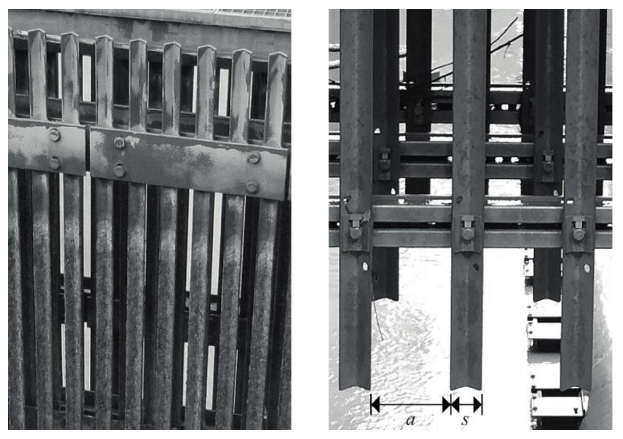
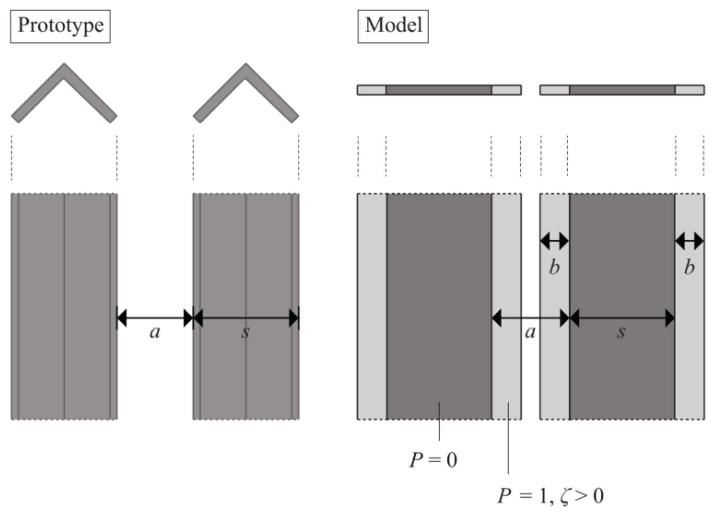
2.2. Modeling of Tranquilizing Racks
2.3. Parameter Study
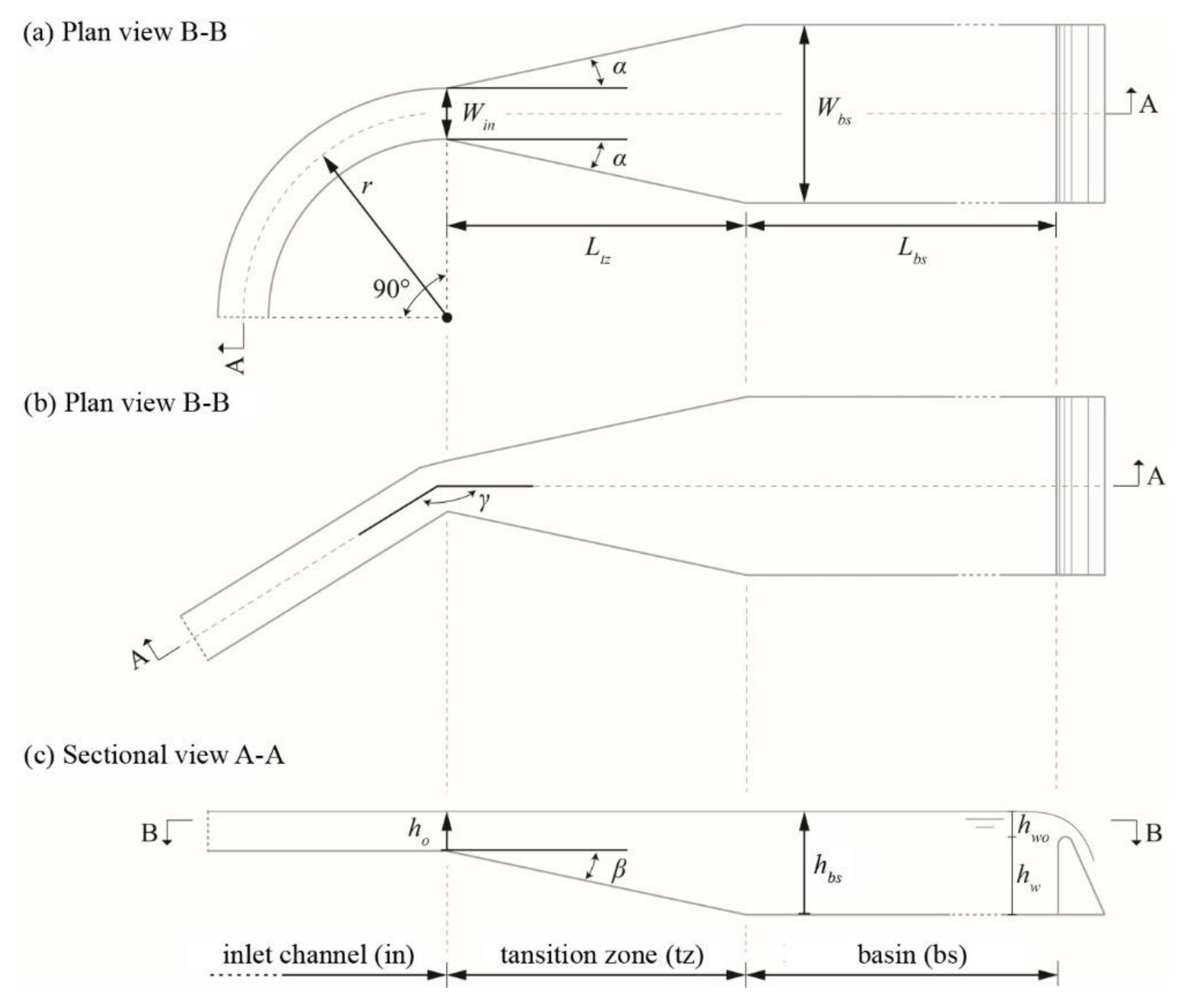
2.3.1. Reference Configuration
2.3.2. Parameter Variation
2.3.3. Evaluation
- Trapping efficiency ηc as ratio of trapped sediment to sediment input, see Equation (1).
- Relative trapping efficiencyas ratio between the trapping efficiency ηc,sim resulting from corresponding parameter study simulations and the trapping efficiency ηc,V0 of the reference configuration V0 for the critical particle diameter dcr = 330 µm. Note that values of ηc,rel above unity indicate that performance of the configuration with given parameter set is better than the setting of the reference configuration, and vice versa.
- Mean basin turbulent kinetic energy (TKE) km is used as an indicator for flow turbulence and presence of eddy structures and hence as a simplified measure for flow inhomogeneity.
- Mean basin bed shear velocity u*m is an estimate for potential resuspension of particles after having settled to the basin bed.
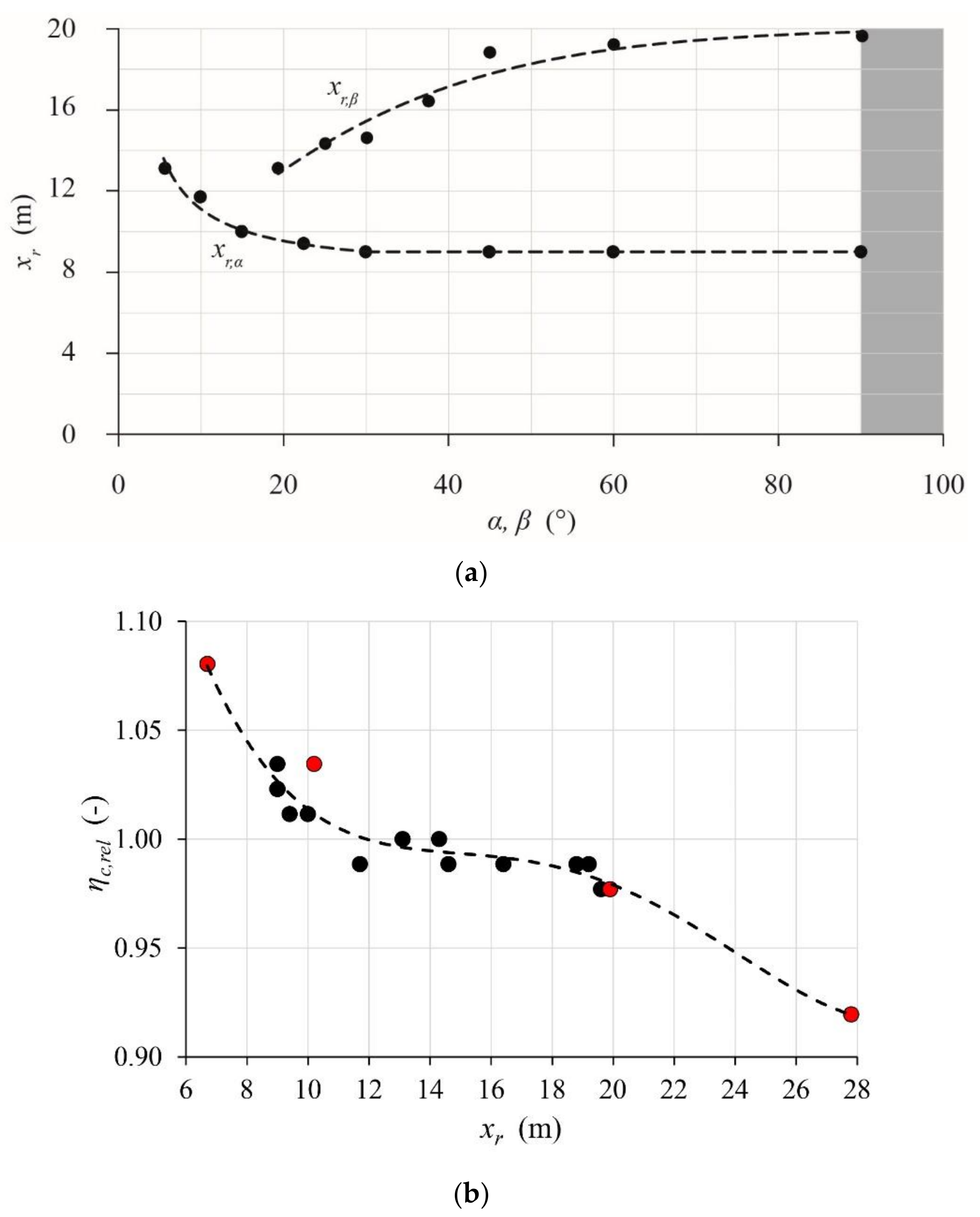
- The size of the recirculating flow zone in the basin is quantified by the length xr representing the extent (in x–z plane) of the transition zone recirculating flow into the basin (Figure 6). The extent of recirculating flow is identified by the area permanently characterized by basin longitudinal flow velocities vx ≤ 0 m/s.
- Extent of weir approach flow, i.e., the effect of the weir on basin flow, is estimated by the distance xup for which incipient streamline upwards deflection occurs over most of the flow depth and the whole basin width upstream of the weir (Figure 7).
3. Results and Discussion
3.1. Validation of Numerical Model
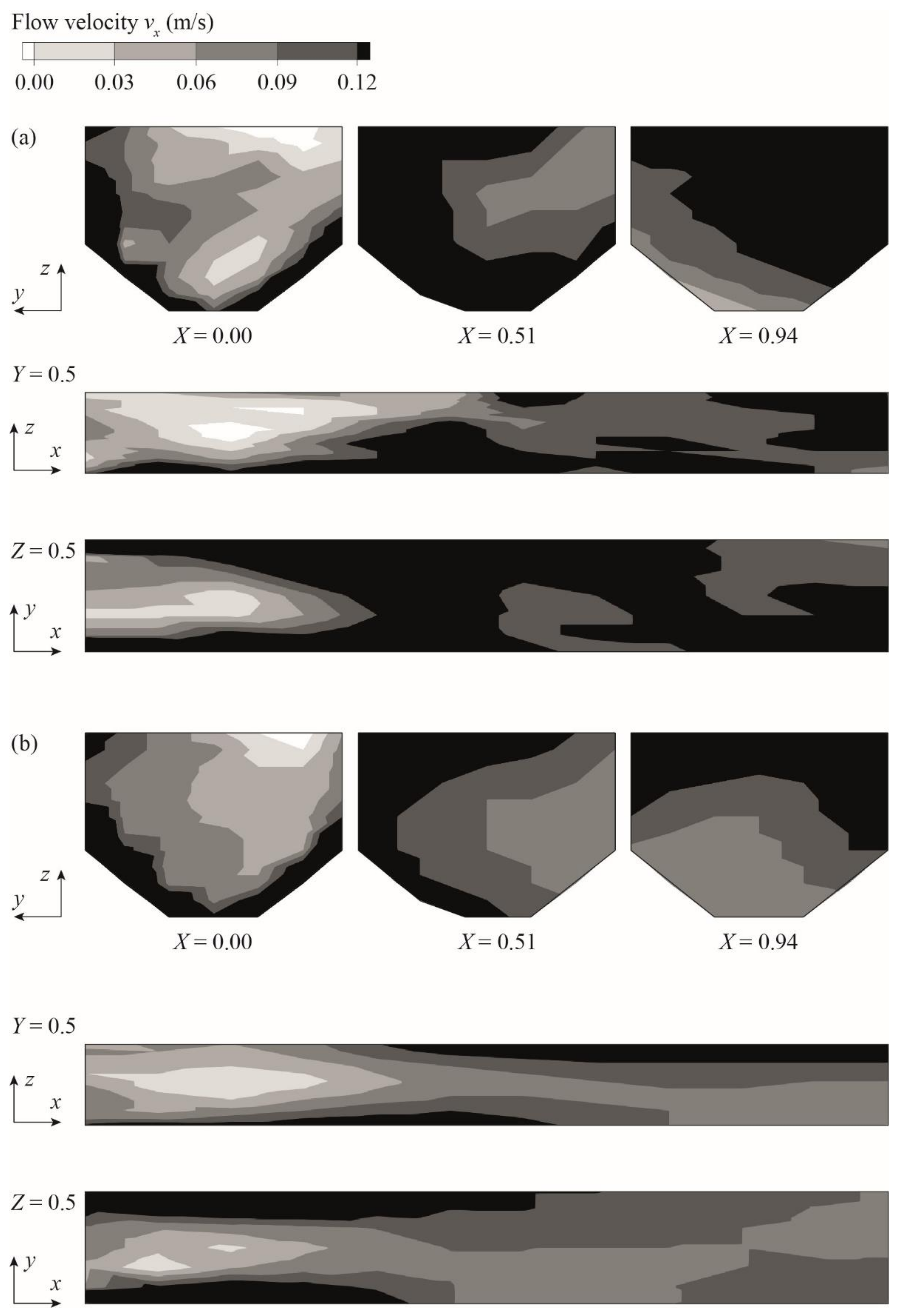
3.1.1. Flow Field
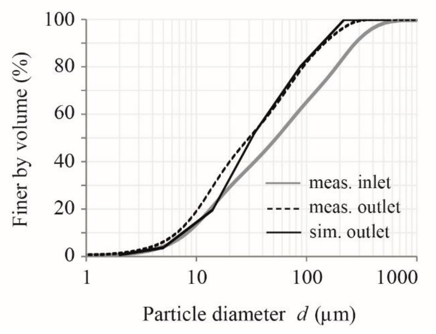
3.1.2. Sediment Transport
3.2. Correlation of Desanding Facility Configuration and Trapping Efficiency
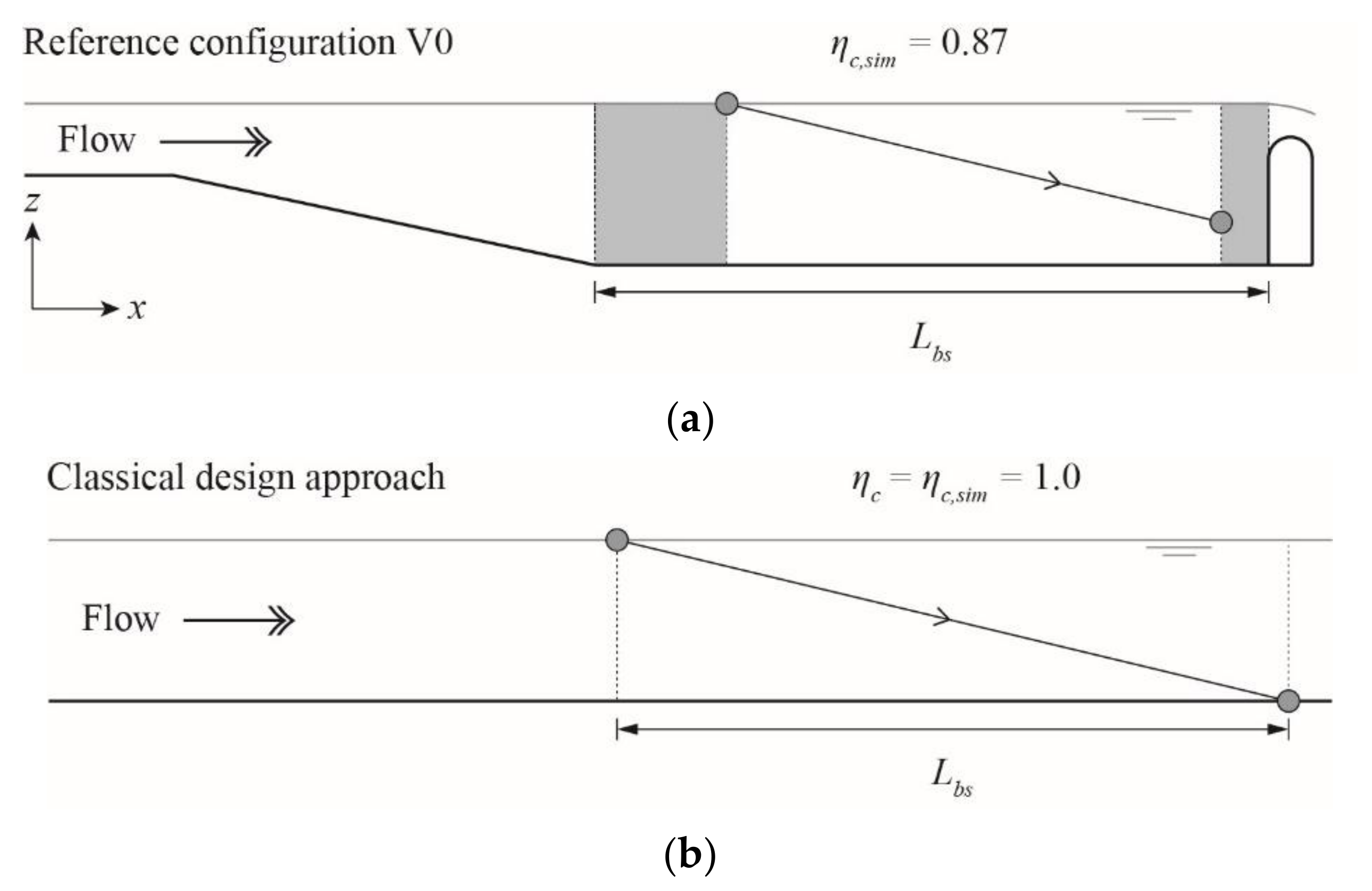
3.2.1. Basin Length
3.2.2. Inlet Channel and Approach Flow Conditions
3.2.3. Transition Zone Geometry and Recirculating Flow
3.2.4. Tranquilizing Racks
3.2.5. Weir
3.2.6. Special Configurations
4. Design Guideline
4.1. General Recommendations
4.2. Enhanced Design Concept
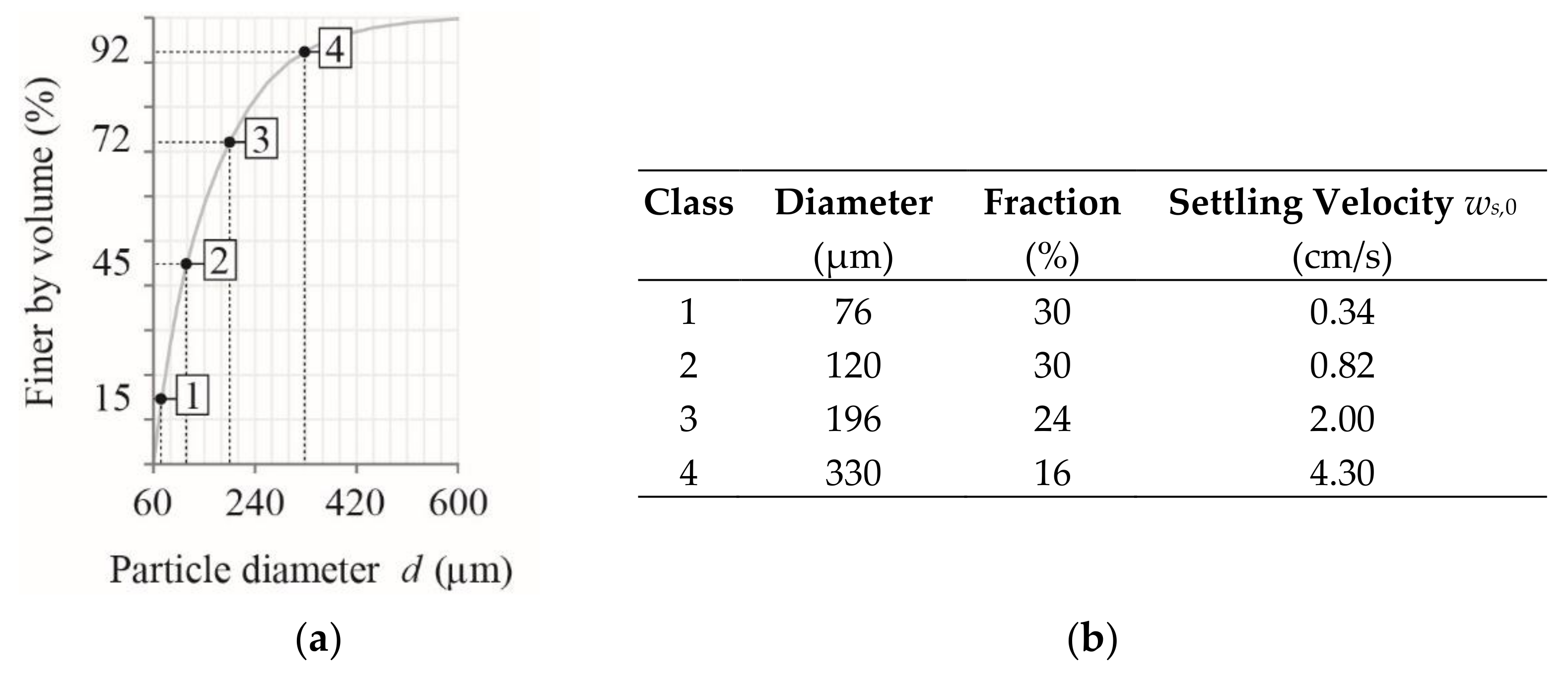
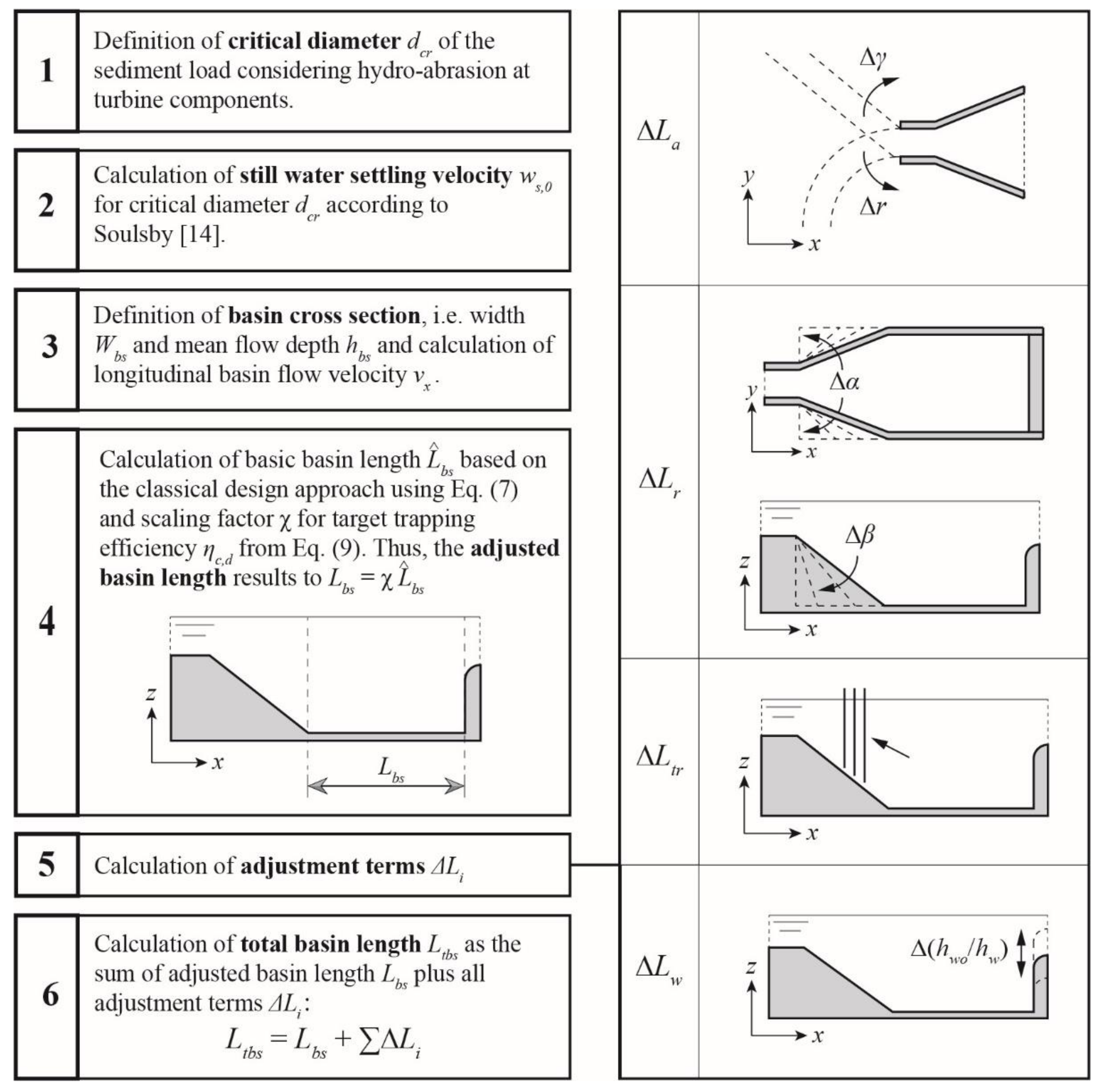
- Definition of critical diameter dcr of the sediment load: The definition of the critical diameter may be based either on concentration-related or mass-related approaches. The smaller the critical grain size, the lower the sediment input into the power waterway and the lower hydro-abrasion at turbine components. However, the lower the critical grain size, the more sediment settles in the basin, potentially increasing flushing water volumes lost for power production. The latter largely depends on the flushing system (e.g., continuous vs. discontinuous). The application of the mass-related approach is only possible when a particle size distribution curve of suspended sediment is available. Typical design values of the critical particle diameter are 0.25 to 0.30 mm for water intakes, from which water is conveyed via a desanding facility directly to turbines, i.e., without passing reservoirs or headwater storage basins that would act as settling ponds.
- Calculation of still-water settling velocity for critical diameter dcr using Equation (2). (Note: The present study and concept are based on the approach of Soulsby [17]; using other approaches is inconsistent and may lead to incorrect results).
- Definition of basin cross section and calculation of longitudinal basin flow velocity: The definition of the basin cross section follows the common recommendation Wbs ≈ 0.8 hbs. Here, hbs is the overall basin mean flow depth, which is typically taken in the middle of the basin in streamwise direction for a sloping basin invert. Often, the cross section is rectangular in the upper part, followed by a constriction in the lower part with slopes of 4:5 (V:H) to facilitate sediment flushing. For the rectangular cross section, the longitudinal mean basin flow velocity vx = Qd/(Wbshbs) can be calculated, where Qd is the basin design discharge. For non-rectangular cross section, the mean wetted basin flow area Amean,bs is considered to result in vx = Qd/Amean,bs.
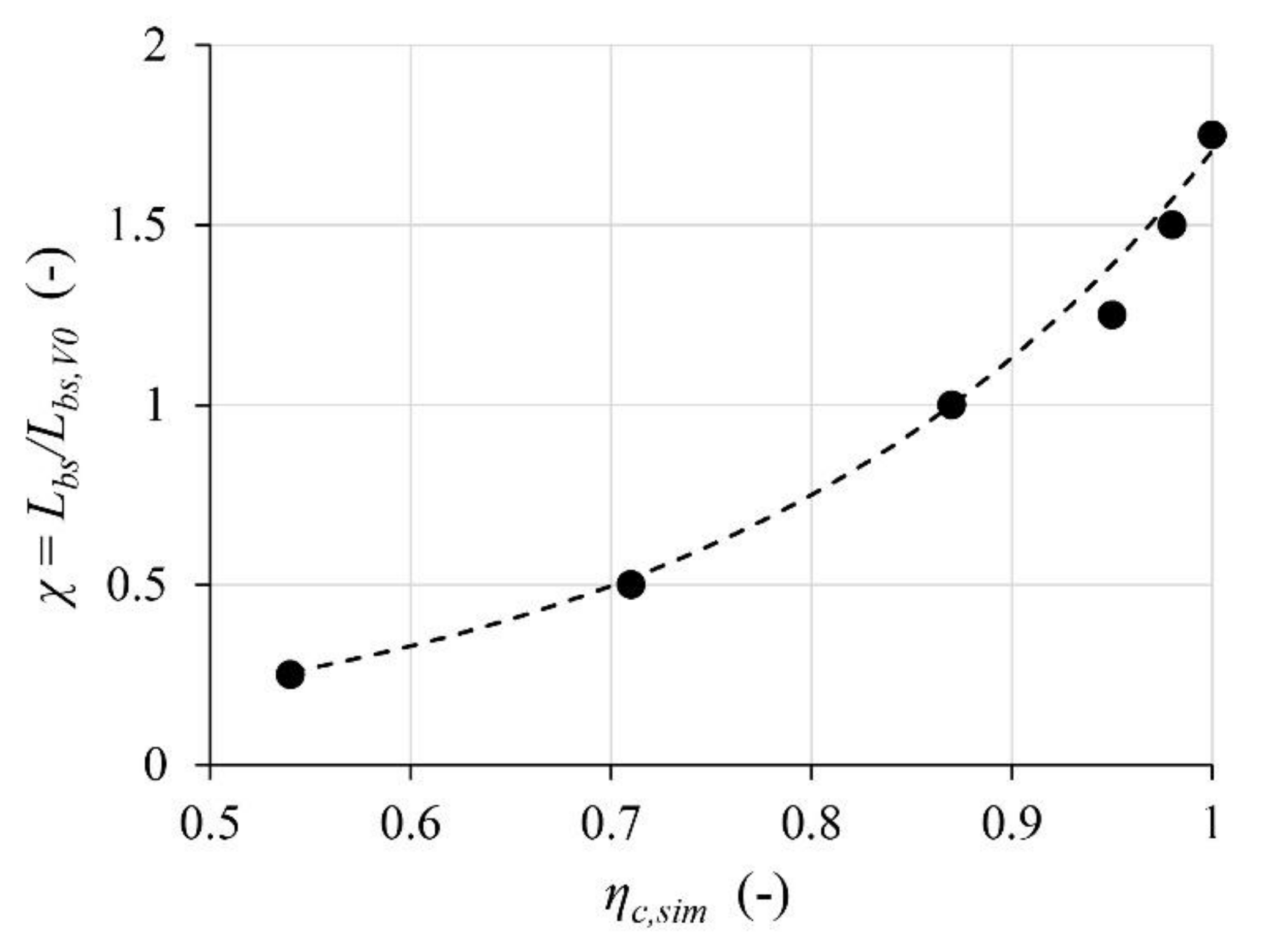
- Calculation of adjusted basin length : First, the basic basin length has to be computed based on the classical design approach using Equation (5). Second, select a target trapping efficiency ηc,d, which may be estimated considering economic aspects and site-specific construction constraints. The larger the target trapping efficiency, the longer the basin, but the lower the sediment input into the power waterway and hydro-abrasive wear at hydraulic machinery. To quantify the latter, turbine erosion models should be applied [30,31,32], allowing for a quantitative cost–benefit assessment of the whole system from desanding facility to hydraulic machines. A design trapping efficiency of ηc,d = 95% is considered meaningful in most cases, resulting in 35% to 40% longer basins compared to the classical approach. Consequently, the scaling factor χ = Lbs/Lbs,V0 (Figure 11) for the target trapping efficiency ηc,d can be determined using Equation (7), and the adjusted basin length results in .
- Calculation of adjustment terms according to Section 3.2:
- Inlet channel geometry and approach flow conditions: with relative trapping efficiency for supercritical approach flow according to Equation (8) and for subcritical approach according to Equation (9);
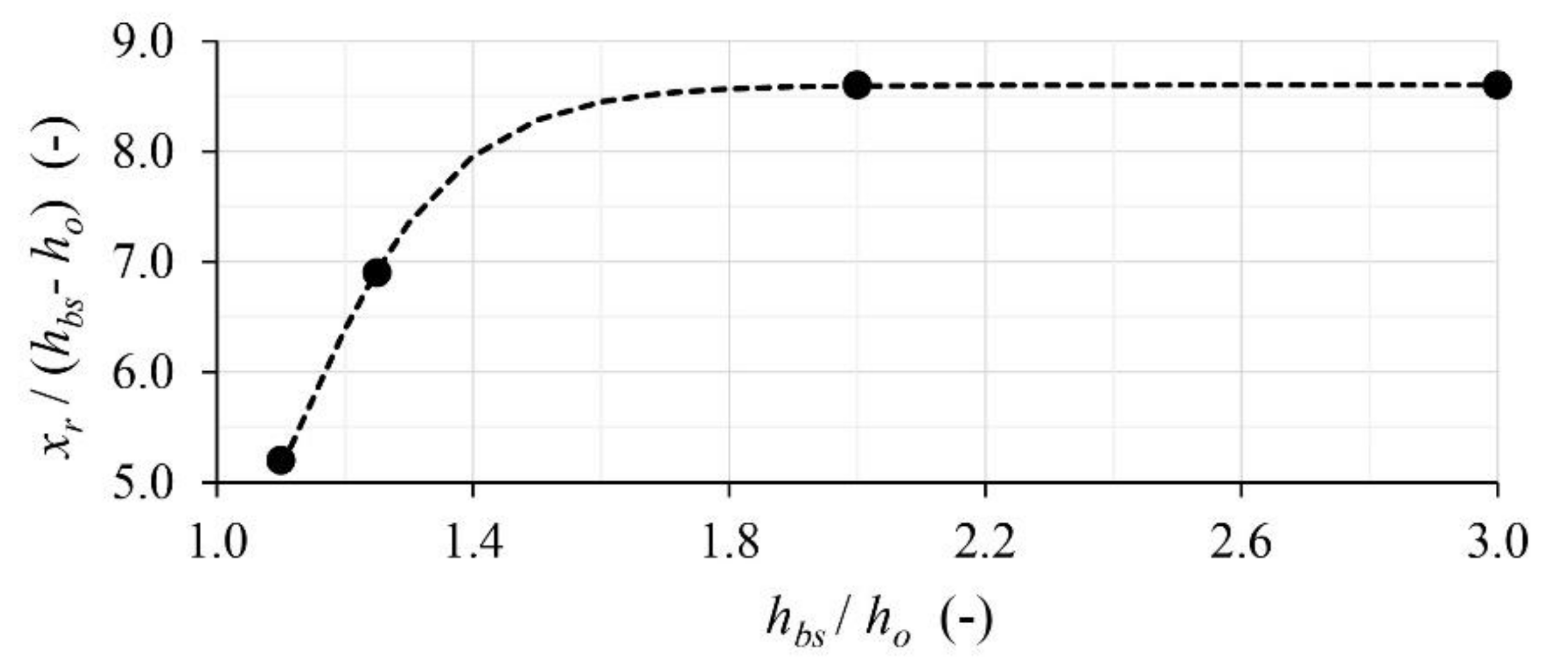
- Transition zone geometry: with relative trapping efficiency according to Equation (12), where the recirculation zone length xr is the maximum value out of Equation (10) (horizontal expansion α), Equation (11) (vertical expansion β) and the complementary Equation (13) (offset in bottom level);
- Tranquilizing racks: with mean increase in relative trapping efficiency according to Equation (14) for subcritical frontal, subcritical curved or angled, or supercritical approach flow;
- Weir: with extent of weir approach flow in terms of distance xup according to Equation (15).
- Calculation of total basin length , i.e., the sum of adjusted basic basin length plus all adjustment terms .
4.3. Application Example
- The critical diameter is an unknown a priori and has to be reckoned back based on the classical design approach. Solving Equation (5) resulted in the still-water vertical settling velocity ws,0 for the given basin length. Consequently, Equation (2) could be solved which resulted in the design particle diameter, representing the critical diameter of the target particle size yielded dcr = 203 μm ≈ 200 μm for water at 5 °C.
- The settling velocity for the critical diameter was obtained in step 1.
- The basin cross section and longitudinal basin flow velocity are given and were determined by field measurements.
- In this example, the basic basin length was equal to the current prototype basin length, corresponding to an arithmetical trapping efficiency of the critical particle size of 87% (see Section 3.2.1, Figure 11). Assuming that maintenance costs due to turbine abrasion are too high for the current facility layout and should be reduced by extending the desander basin in the streamwise direction, to achieve a target trapping efficiency of 95%, the target basic basin length became = 1.39 ∙ 35 m = 48.65 m.
- Adjustment terms:
- Inlet channel geometry and approach flow conditions: for subcritical flow and γ = 158°, ΔLa = (1 − 1.031) ∙ 35 m = −1.09 m;
- Transition zone geometry: with = 10.7 m from Equation (10), = 12.7 m from Equation (11) and = 15.0 m from Equation (13) for an expansion ratio 2.13 and a step height 1.74 m, the critical relative trapping efficiency due to recirculating flow became from Equation (12), so that ΔLr = (1 − 0.992) ∙ 35 m = 0.27 m;
- Tranquilizing racks: for a subcritical, asymmetric (angled) approach flow from Equation (14) ΔLtr = (1 − 1.09) ∙ 35 m = –3.15 m;
- Weir: for 0.10 from Equation (15) ΔLw = = 6.30 m.
- The total basin length required to achieve 95% trapping of particles dcr = 200 μm resulted from Ltbs = 48.65 m − 1.09 m + 0.27 m − 3.15 m + 6.30 m ≈ 51 m.
5. Conclusions
Author Contributions
Funding
Institutional Review Board Statement
Acknowledgments
Conflicts of Interest
Appendix A
| Variation | r | γ | Ltz | α | β | Lbs | Fo |
|---|---|---|---|---|---|---|---|
| (m) | (°) | (m) | (°) | (°) | (m) | (–) | |
| V0 | ∞ | 180 | 10 | 5.7 | 19.3 | 32 | 0.35 |
| V1.1 | 2 | – | 10 | 5.7 | 19.3 | 32 | 0.35 |
| V1.2 | 10 | – | 10 | 5.7 | 19.3 | 32 | 0.35 |
| V1.3 | 20 | – | 10 | 5.7 | 19.3 | 32 | 0.35 |
| V1.4 | 5 | – | 10 | 5.7 | 19.3 | 32 | 0.35 |
| V2.1 | ∞ | 180 | 10 | 90 | 19.3 | 32 | 0.35 |
| V2.2 | ∞ | 180 | 10 | 60 | 19.3 | 32 | 0.35 |
| V2.3 | ∞ | 180 | 10 | 45 | 19.3 | 32 | 0.35 |
| V2.4 | ∞ | 180 | 10 | 30 | 19.3 | 32 | 0.35 |
| V2.5 | ∞ | 180 | 10 | 15 | 19.3 | 32 | 0.35 |
| V2.6 | ∞ | 180 | 10 | 10 | 19.3 | 32 | 0.35 |
| V2.7 | ∞ | 180 | 10 | 22.5 | 19.3 | 32 | 0.35 |
| V3.1 | ∞ | 180 | 10 | 5.7 | 90 | 32 | 0.35 |
| V3.2 | ∞ | 180 | 10 | 5.7 | 60 | 32 | 0.35 |
| V3.3 | ∞ | 180 | 10 | 5.7 | 45 | 32 | 0.35 |
| V3.4 | ∞ | 180 | 10 | 5.7 | 30 | 32 | 0.35 |
| V3.5 | ∞ | 180 | 10 | 5.7 | 25 | 32 | 0.35 |
| V3.6 | ∞ | 180 | 10 | 5.7 | 37.5 | 32 | 0.35 |
| V4.1 | ∞ | 180 | 0 | 90 | 90 | 32 | 0.35 |
| V4.2 | ∞ | 180 | 5 | 11.3 | 35 | 32 | 0.35 |
| V4.3 | ∞ | 180 | 15 | 3.8 | 13.1 | 32 | 0.35 |
| V4.4 | ∞ | 180 | 20 | 2.9 | 9.9 | 32 | 0.35 |
| V5.3 | ∞ | 180 | 10 | 5.7 | 19.3 | 32 | 2.0 |
| V5.4 | ∞ | 180 | 10 | 5.7 | 19.3 | 32 | 3.5 |
| V6.3 | based on V0, but with continuously expanding basin area | ||||||
| V6.5 | based on V0, but with impact wall at end of transition zone (TZ) | ||||||
| V6.9 | based on V0, but with longitudinal vertical walls in TZ | ||||||
| V6.10 | based on V0, but with both-sided vertical inclined plates in basin | ||||||
| V6.13 | based on V0, but with horizontal flow deflection plates at beginning of TZ | ||||||
| V6.14 | based on V0, but with horizontal flow deflection plates and tranquillizing racks in TZ | ||||||
| V7.1 | ∞ | 180 | 10 | 5.7 | 19.3 | 8 | 0.35 |
| V7.2 | ∞ | 180 | 10 | 5.7 | 19.3 | 16 | 0.35 |
| V7.3 | ∞ | 180 | 10 | 5.7 | 19.3 | 40 | 0.35 |
| V7.4 | ∞ | 180 | 10 | 5.7 | 19.3 | 48 | 0.35 |
| V7.5 | ∞ | 180 | 10 | 5.7 | 19.3 | 56 | 0.35 |
| V8.1 | ∞ | 160 | 10 | 5.7 | 19.3 | 32 | 0.35 |
| V8.2 | ∞ | 140 | 10 | 5.7 | 19.3 | 32 | 0.35 |
| V8.3 | ∞ | 120 | 10 | 5.7 | 19.3 | 32 | 0.35 |
| V8.4 | ∞ | 170 | 10 | 5.7 | 19.3 | 32 | 0.35 |
| V8.5 | ∞ | 150 | 10 | 5.7 | 19.3 | 32 | 0.35 |
| V8.6 | ∞ | 130 | 10 | 5.7 | 19.3 | 32 | 0.35 |
Appendix B
| Variation | kt,m | u*m | xr | xup | ηc,sim | ηc,sim/ηc,V0 |
|---|---|---|---|---|---|---|
| (cm2/s2) | (cm/s) | (m) | (m) | (–) | (–) | |
| V0 | 249 | 1.0 | 13.1 | 6 | 0.87 | 1.00 |
| V0_r | 62 | 0.5 | 25.2 | n/a | 0.92 | 1.06 |
| V1.1 | 198 | 3.1 | 10.9 | n/a | 0.85 | 0.98 |
| V1.1_r | 66 | 2.6 | 9.8 | n/a | 0.94 | 1.08 |
| V1.2 | 185 | 1.8 | 14.4 | n/a | 0.91 | 1.05 |
| V1.3 | 211 | 1.2 | 15.3 | n/a | 0.90 | 1.03 |
| V1.4 | 203 | 3.0 | 11.4 | n/a | 0.85 | 0.98 |
| V2.1 | 232 | 0.9 | 9.0 | 6 | 0.89 | 1.02 |
| V2.1_r | 83 | 0.5 | 21.3 | n/a | 0.94 | 1.08 |
| V2.2 | 233 | 0.9 | 9.0 | 6 | 0.89 | 1.02 |
| V2.3 | 233 | 0.9 | 9.0 | 6 | 0.90 | 1.03 |
| V2.4 | 234 | 0.9 | 9.0 | 6 | 0.89 | 1.02 |
| V2.5 | 247 | 1.0 | 10.0 | 6 | 0.88 | 1.01 |
| V2.5_r | 63 | 0.4 | 23.2 | n/a | 0.93 | 1.07 |
| V2.6 | 248 | 1.0 | 11.7 | 6 | 0.86 | 0.99 |
| V2.7 | 238 | 1.0 | 9.4 | 6 | 0.88 | 1.01 |
| V3.1 | 365 | 1.5 | 19.6 | 5 | 0.85 | 0.98 |
| V3.1_r | 83 | 0.7 | 32.0 | n/a | 0.91 | 1.05 |
| V3.2 | 354 | 1.3 | 19.2 | 5 | 0.86 | 0.99 |
| V3.3 | 345 | 1.3 | 18.8 | 5 | 0.86 | 0.99 |
| V3.4 | 302 | 1.1 | 14.6 | 6 | 0.86 | 0.99 |
| V3.5 | 277 | 1.1 | 14.3 | 6 | 0.87 | 1.00 |
| V3.6 | 340 | 1.2 | 16.4 | 6 | 0.86 | 0.99 |
| V4.1 | 400 | 1.6 | 27.8 | 3 | 0.80 | 0.92 |
| V4.2 | 336 | 1.2 | 19.9 | 5 | 0.85 | 0.98 |
| V4.3 | 198 | 0.9 | 10.2 | 6 | 0.9 | 1.03 |
| V4.4 | 149 | 0.8 | 6.7 | 6 | 0.94 | 1.08 |
| V5.3 | 437 | 3.9 | 15.0* | n/a | 0.77 | 0.89 |
| V5.4 | 528 | 4.0 | 15.1* | n/a | 0.76 | 0.87 |
| V5.4_r | 246 | 3.8 | 21.3* | n/a | 0.91 | 1.05 |
| V6.3 | 175 | 0.4 | 0.0 | n/a | 0.89 | 1.02 |
| V6.5 | 90 | 1.9 | 7.4 | n/a | 0.91 | 1.05 |
| V6.9 | 276 | 1.4 | 26.7 | n/a | 0.93 | 1.07 |
| V6.10 | 246 | n/a | 6.5 | n/a | 0.90 | 1.03 |
| V6.13 | 64 | 1.9 | 0.0 | n/a | 0.98 | 1.13 |
| V6.14 | 14 | 0.8 | 0.0 | n/a | 0.98 | 1.13 |
| V7.1 | 284 | 1.7 | 8.0 | n/a | 0.54 | 0.62 |
| V7.2 | 356 | 1.2 | 16.0 | n/a | 0.71 | 0.82 |
| V7.3 | 181 | 1.0 | 13.1 | 6 | 0.95 | 1.09 |
| V7.4 | 174 | 1.0 | 13.1 | 6 | 0.98 | 1.13 |
| V7.5 | 165 | 1.0 | 13.1 | 6 | ≈1.0 | 1.15 |
| V8.1 | 222 | 1.2 | 14.3 | n/a | 0.90 | 1.03 |
| V8.2 | 226 | 1.7 | 12.3 | n/a | 0.89 | 1.02 |
| V8.3 | 277 | 3.2 | 11.6 | n/a | 0.82 | 0.94 |
| V8.3_r | 100 | 2.9 | 10.6 | n/a | 0.89 | 1.02 |
| V8.4 | 269 | 0.9 | 10.6 | n/a | 0.88 | 1.01 |
| V8.5 | 208 | 1.8 | 12.9 | n/a | 0.89 | 1.02 |
| V8.6 | 253 | 2.9 | 11.9 | n/a | 0.86 | 0.99 |
Appendix C
| Parameter | Description | Investigated Values | Units | |
|---|---|---|---|---|
| Lower | Upper | |||
| Lbs | Basin length | 8 | 56 | m |
| Fo | Inlet channel Froude number | 0.35 | 3.5 | – |
| r | Inlet channel radius | 2 | 20 | m |
| γ | Inlet channel conjunction angle | 120 | 180 | ° (angle) |
| α | Transition zone horizontal expansion angle | 5.7 | 90 | ° (angle) |
| β | Transition zone vertical expansion angle | 19.3 | 90 | ° (angle) |
| dcr | Critical particle diameter | 0.06 | 2 | mm |
| hwo/hw | Relative weir overflow depth | 0.14 | 0.67 | – |
References
- Felix, D.; Albayrak, I.; Abgottspon, A.; Boes, R.M. Hydro-abrasive erosion of hydraulic turbines caused by sediment—A century of research and development. In Proceedings of the 28th IAHR Symposium on Hydraulic Machinery and Systems, Grenoble, France, 4–8 July 2016. [Google Scholar]
- Beniston, M.; Farinotti, D.; Stoffel, M.; Andreassen, L.M.; Coppola, E.; Eckert, N.; Fantini, A.; Giacona, F.; Hauck, C.; Huss, M.; et al. The European mountain cryosphere: A review of its current state, trends, and future challenges. Cryosphere 2018, 12, 759–794. [Google Scholar] [CrossRef] [Green Version]
- Camp, T.R. A study of the rational design of settling tanks. Sew. Work. J. 1936, 8, 742–758. [Google Scholar]
- Garde, R.J.; Ranga Raju, K.G.; Sujudi, A.W.R. Design of settling basins. J. Hydraul. Res. 1990, 28, 81–91. [Google Scholar] [CrossRef]
- Ortmanns, C.; Minor, H.E. Flow and turbulence conditions on the design of desilting chambers. Dam Eng. 2007, 17, 257–270. [Google Scholar]
- Velikanov, M.A. Theory of probability applied to analysis of sedimentation of silt in turbulent streams. Trans. Sci. Res. Inst. Hydrotech. 1936, 18, 55–56. [Google Scholar]
- Simanjuntak, T.; Boeriu, P.; Dano Roelvink, J. Consideration on the Sedimentation Process in a Settling Basin. J. Hydrol. Hydromech. 2009, 57, 16–25. [Google Scholar] [CrossRef] [Green Version]
- Qamar, M.Z.; Verma, M.K.; Meshram, A.P. Importance of Desilting Basins in Run-of-River Hydro Projects in Himalayan Region. Int. J. Emerg. Technol. Adv. Eng. 2014, 4, 407–412. [Google Scholar]
- Lysne, D.K.; Glover, B.; Støle, H.; Tesaker, E. Hydraulic Design; Norwegian University of Science and Technology, Department of Hydraulic and Environmental Engineering: Trondheim, Norway, 2003. [Google Scholar]
- Paschmann, C.; Fernandes, J.N.; Vetsch, D.F.; Boes, R.M. Assessment of flow field and sediment flux at alpine desanding facilities. Int. J. River Basin Manag. 2017, 15, 287–295. [Google Scholar] [CrossRef] [Green Version]
- Paschmann, C.; Fernandes, J.N.; Vetsch, D.F.; Boes, R.M. Experimental setup for flow and sediment flux characterization at desanding facilities. Flow Meas. Instrum. 2017, 54, 197–204. [Google Scholar] [CrossRef] [Green Version]
- Paschmann, C.; Albayrak, I.; Vetsch, D.F.; Boes, R.M. Preliminary Study on the Review and Evaluation of CFD Software for the Modeling of Flow, Sediment Deposit and Transport Processes in Desilting Facilities of Alpine Hydropower Plants; Swiss Federal Office of Energy: Bern, Switzerland, 2015; Available online: https://www.aramis.admin.ch/Texte/?ProjectID=34181 (accessed on 9 November 2021). (In German)
- Ferreira, A.D.; Sousa, A.C.M. The RNG Turbulence Closure: Application and Revisited Performance Assessment. WSEAS Trans. Syst. 2002, 1, 165–170. [Google Scholar]
- Spasojevic, M.; Holly, F.M. Two- and Three-Dimensional Numerical Simulation of Mobile-Bed Hydrodynamics and Sedimentation. In Sedimentation Engineering; Gracia, M., Ed.; ASCE Manuals and Reports on Engineering Practice No. 110; ASCE: Reston, VI, USA, 2008; pp. 683–761. [Google Scholar]
- Olsen, N.R.B.; Skoglund, M. Three-dimensional numerical modeling of water and sediment flow in a sand trap. J. Hydraul. Res. 1994, 32, 833–844. [Google Scholar] [CrossRef]
- Ruether, N.; Singh, J.M.; Olsen, N.R.B.; Atkinson, E. 3-D computation of sediment transport at water intakes. Proc. Inst. Civ. Eng.-Water Manag. 2005, 158, 1–7. [Google Scholar] [CrossRef]
- Soulsby, R.L. Dynamics of Marine Sands—A Manual for Practical Applications; Telford: London, UK, 1997. [Google Scholar]
- Richardson, J.F.; Zaki, W.N. Sedimentation and Fluidsation: Part I. Chem. Eng. Res. Des. 1954, 32, 35–53. [Google Scholar] [CrossRef]
- Mastbergen, D.R.; Van Den Berg, J.H. Breaching in fine sands and the generation of sustained turbidity currents in submarine canyons. Sedimentology 2003, 50, 625–637. [Google Scholar] [CrossRef]
- Rodi, W. Turbulence Models and Their Application in Hydraulics, 3rd ed.; Routledge: London, UK, 2000. [Google Scholar]
- Rijn, L.C.v. Sediment Transport, Part I: Bed Load Transport. J. Hydraul. Eng. 1984, 110, 1431–1456. [Google Scholar] [CrossRef] [Green Version]
- Flow Science Inc. Manual: FLOW-3D Version 11.2. 2017. Available online: https://www.flow3d.com (accessed on 9 November 2021).
- Paschmann, C. Design Optimization of Desanding Facilities for Hydropower Schemes; Boes, R.M., Ed.; Versuchsanstalt für Wasserbau, Hydrologie und Glaziologie (VAW), ETH Zürich: Zürich, Switzerland, 2018; Volume 247. [Google Scholar]
- Tsikata, J.M.; Tachie, M.F.; Katopodis, C. Open-channel turbulent flow through bar racks. J. Hydraul. Res. 2014, 52, 630–643. [Google Scholar] [CrossRef]
- Vischer, D.; Huber, A. Wasserbau—Hydrologische Grundlagen, Elemente des Wasserbaus, Nutz- und Schutzbauten an Binnengewässern; Springer: Berlin, Germany, 2002. [Google Scholar]
- Mosonyi, E. Water Power Development; Publishing House of the Hungarian Academy of Sciences: Budapest, Hungary, 1956. [Google Scholar]
- Wu, W.; Wang, S.S.Y. Formulas for Sediment Porosity and Settling Velocity. J. Hydraul. Eng. 2006, 132, 858–862. [Google Scholar] [CrossRef]
- Zanke, U.C.E. Grundlagen der Sedimentbewegung; Springer: Berlin, Germany, 1982. [Google Scholar]
- Durst, F.; Tropea, C. Flows over Two-Dimensional Backward—Facing Steps. In Structure of Complex Turbulent Shear Flow: Symposium, Marseille, France August 31–September 3, 1982; Dumas, R., Fulachier, L., Eds.; Springer: Berlin/Heidelberg, Germany, 1983; pp. 41–52. [Google Scholar]
- IEC—Intl. Electrotechnical Commission Technical Committee 4: Hydraulic turbines. Hydraulic Machines—Guide for Dealing with Hydro-Abrasive Erosion in Kaplan, Francis, and Pelton Turbines; IEC: Geneva, Switzerland, 2013; Volume IEC 62364. [Google Scholar]
- Felix, D. Experimental Investigation on Suspended Sediment, Hydro-Abrasive Erosion and Efficiency Reductions of Coated Pelton Turbines; Boes, R.M., Ed.; Versuchsanstalt für Wasserbau, Hydrologie und Glaziologie (VAW), ETH Zürich: Zürich, Switzerland, 2017; Volume 238. [Google Scholar]
- Felix, D.; Abgottspon, A.; Albayrak, I.; Boes, R.M. Hydro-abrasive erosion on coated Pelton runners: Partial calibration of the IEC model based on measurements in HPP Fieschertal. Proc. IOP Conf. Ser. Earth Environ. Sci. 2016, 49, 122009. [Google Scholar] [CrossRef] [Green Version]



| Parameter | Description | Investigated Values |
|---|---|---|
| Lbs (m) | Basin length | 8, 16, 32, 40, 48, 56 |
| Fo (–) | Inlet channel Froude number | 0.35, 2.0, 3.5 |
| r (m) | Inlet channel radius | 2, 5, 10, 20 |
| γ (°) | Inlet channel conjunction angle | 180, 170, 160, 150, 140, 130, 120 |
| α (°) | Transition zone horizontal expansion angle | 5.7, 10, 15, 22.5, 30, 45, 60, 90 |
| β (°) | Transition zone vertical expansion angle | 19.3, 25, 30, 37.5, 45, 60, 90 |
| Ltz (m) | Transition zone length | 0, 5, 10, 15, 20 |
| Data Set | Cin (g/L) | d50,in (µm) | Cout,p v(g/L) | ηc,p (–) | Cout,s (g/L) | ηc,s (–) |
|---|---|---|---|---|---|---|
| t1 | 0.34 | 22 | 0.08 | 0.76 | 0.27 | 0.32 |
| t2 | 2.26 | 67 | 0.67 | 0.70 | 1.17 | 0.59 |
| t3 | 1.10 | 121 | 0.25 | 0.77 | 0.45 | 0.70 |
Publisher’s Note: MDPI stays neutral with regard to jurisdictional claims in published maps and institutional affiliations. |
© 2022 by the authors. Licensee MDPI, Basel, Switzerland. This article is an open access article distributed under the terms and conditions of the Creative Commons Attribution (CC BY) license (https://creativecommons.org/licenses/by/4.0/).
Share and Cite
Paschmann, C.; Vetsch, D.F.; Boes, R.M. Design of Desanding Facilities for Hydropower Schemes Based on Trapping Efficiency. Water 2022, 14, 520. https://doi.org/10.3390/w14040520
Paschmann C, Vetsch DF, Boes RM. Design of Desanding Facilities for Hydropower Schemes Based on Trapping Efficiency. Water. 2022; 14(4):520. https://doi.org/10.3390/w14040520
Chicago/Turabian StylePaschmann, Christopher, David F. Vetsch, and Robert M. Boes. 2022. "Design of Desanding Facilities for Hydropower Schemes Based on Trapping Efficiency" Water 14, no. 4: 520. https://doi.org/10.3390/w14040520
APA StylePaschmann, C., Vetsch, D. F., & Boes, R. M. (2022). Design of Desanding Facilities for Hydropower Schemes Based on Trapping Efficiency. Water, 14(4), 520. https://doi.org/10.3390/w14040520


