Article

Operation Performance and Seepage Flow of Impervious Body in Blast-Fill Dams Using Discrete Element Method and Measured Data

1
State Key Laboratory of Eco-Hydraulics in Northwest Arid Region of China, Institute of Water Resources and Hydroelectric Engineering, Xi’an University of Technology, Xi’an 710048, China
2
Upstream Hydrology and Water Resources Bureau of Yellow River Conservancy Commission, Lanzhou 730000, China
*
Author to whom correspondence should be addressed.
Water 2022, 14(9), 1443; https://doi.org/10.3390/w14091443
Submission received: 11 April 2022 / Revised: 25 April 2022 / Accepted: 28 April 2022 / Published: 30 April 2022
(This article belongs to the Special Issue Safety Monitoring and Management of Reservoir and Dams)

Abstract

:
As a high-efficiency and low-investment method of dam construction, blast-fill dams have been widely used in water conservancy, mining engineering, soil and water conservation, disaster prevention and other projects. Through collecting data on the main projects of the blast-fill dams, the characteristics and development trends of blast-fill dams are analyzed in detail. Meanwhile, the design requirements of impervious bodies in the initial and reinforcement stages are systematically reviewed. Subsequently, with measured data of a typical blast-fill dam, the structural characteristics of blast-fill dams after blasting and the validity of the phreatic line height after reinforcement are analyzed using the discrete element method. We conclude that an appropriate construction schedule and flexible impervious material are critical features of the impervious body for a dam with large deformation. When the dam deformation is stable, a secondary treatment should be considered for the impervious body to improve the dam safety. The design ideas for the impervious body of blast-fill dams are also applicable to other dam types with large deformation for risk reduction, such as high rockfill dams, soft-rock dams and tailings dams, and have a certain significance for reference in the treatment of landslides and confined lakes.

1. Introduction

Rockfill dams have become one of the most preferred dam types for many projects because they are very adaptable and are convenient to construct. Rockfill dam heights now approach 300 m [1,2]. As one of the main types of rockfill dams, blast-fill dams have been widely studied and applied in Asian countries, such as China, the Soviet Union and Kyrgyzstan, because of the limited transportation requirements, short construction time and low investment required for such dams [3]. During the period of the Seventh Five-Year Plan, in-depth research on blast-fill dams was carried out as part of a key research project in China. At present, some blast-fill dam technologies in China have reached an advanced level, internationally [4]. In recent years, with the rapid improvement in economic strength and dam technology, blast-fill dams in hydraulic engineering have gradually entered operation and aging periods, while blast-fill dams are still in their infancy in tailings management, soil and water conservation, disaster prevention and mitigation, etc. In addition, with the emergence of new problems concerning landslides, confined lakes, abandoned slag dams, soft-rock dams, etc., the design, operation, management and safety of blast-fill dams again gained considerable attention from scholars [5,6].
The Asian countries are the main areas where blast-fill dams were established, developed and promoted. The construction technology of blast-fill dams has been thoroughly studied and widely applied, and blast-fill dams are still in use in Asian countries. In 1935, directional blasting technology was first used by the Soviet Union for river closure in hydraulic engineering. To quickly mitigate the threat of mudslides in Almaty, Mikhail Lavrentyev, a mathematician and blasting and fluid mechanics expert in the Soviet Union, presided over the famous Alma-Ata dam in 1966. He established a systematic theory of blast-fill dam design; then, more than 20 blast-fill dams were built in the Soviet Union [7]. To build the 280 m high Kambarata I hydropower station, the test dams Burlykia and Uch-Terek were constructed by the Soviet Union [8,9], and the directional blasting of the Kambarata II hydropower station was completed in 2009 [10,11]. Since the first blast-fill dam was built in Xingtai, Hebei, in 1959, more than 60 blast-fill dams have been constructed successively in China, accumulating rich experience in blast-fill dam technology. A number of scholars have carried out a series of tests and observations on the blasting, seepage and operation of blast-fill dams. Chen et al. [12] analyzed the particle composition and seepage flow of blast-fill dams, based on exploratory sampling tests and monitoring data, respectively. Using a probabilistic method, the reduction effect on the porosity and seepage of blast-fill dams with warping irrigation was evaluated by Xi et al. [13]. Based on the common characteristics between blast-fill dams and natural landslides, a rigid body model was established by Adushkin [14] for landslide warning and forecasting. Yan et al. [15] studied the feasibility of building dams with directional blasting in soil and water conservation projects. The feasibility of transforming a confined lake into a reservoir with blast-fill dams was investigated by Evans et al. [16]. Relationships between the index properties and strength parameters of blasted rockfill materials were developed [17]. Lu et al. [18] analyzed the advantages and disadvantages of different reinforcement measures of blast-fill dams, such as geomembrane and concrete cutoff walls.
In recent years, blast-fill dams have attracted attention again as a special dam construction between natural environments and artificial control. The design essentials and operation management experience of blast-fill dams were used in soil and water conservation, disaster prevention and mitigation and tailings dam projects by many scholars; additionally, blast-fill dams were used to solve new problems concerning landslides, confined lakes, abandoned slag dams and soft-rockfill dams. In addition, blast-fill dams built in the last century have gradually entered the aging period, and there is an urgent need to reinforce these dams. Therefore, the design requirements in the initial and reinforcement stages of blast-fill dams are summarized in this paper. Then, the design and operation experiences with impervious bodies are analyzed for a typical blast-fill dam using the discrete element method (DEM) and measured data, which are expected to provide a reference for the design of impervious bodies of other rockfill dams and the treatment of landslides.

2. Statistics on Blast-Fill Dams

As an efficient dam-construction means, blast-filling has achieved a balance between engineering investment and benefits, and blast-fill-dam construction can be efficiently completed under the topography, materials and investment constraints. First, explosives are buried in a dam abutment and the rock mass is instantaneously detonated by explosives. Then, the river valley is filled with the rock mass created by the explosion, providing all or part of the dam filling. Finally, according to the engineering design requirements, the surface layer of the blasting rockfill is trimmed, and it is decided whether dam heightening and waterproofing are necessary [19].
The advantages of blast-fill dams are as follows: (1) Fast filling speed. The filling of the main dam body is completed by blasting, which can be used in river closure projects to save time and cost. (2) Strong adaptability. Due to the few requirements of site selection, entry traffic and construction site layout, blast-fill technology is suitable for sites with inconvenient transportation options or narrow terrain, such as alpine valleys and virgin forests. (3) Low investment. Because all or part of the dam fill is created with explosives, the costs of earth-rock excavation, transportation, filling and compaction required in conventional hydraulic engineering are saved, also reducing damage to the environment. (4) More economic benefits. After blasting, generator sets can be put into operation in advance. With the advantages of less investment and early output, dynamic investment in the engineering is greatly reduced [20]. Meanwhile, there are some problems with blast-fill dams, such as the design complexity considerations, diversion building layout, large blasting-affected areas, long-term deformation of the dam body, and the high risk of damage to the impervious body [21].
The statistics on the main blast-fill dams are given in Table 1 [7,15,22,23,24,25], which shows the following results: (1) In the 1970s, the application of directional blasting technology in hydraulic engineering reached a climax. (2) There are usually no impervious measures carried out for blast-fill dams built by the Soviet Union, while blast-fill dams in China usually have impervious bodies due to hydraulic engineering, such as inclined asphalt concrete cores (IACCs). (3) The advantages of directional blasting technology can be fully utilized in soil and water conservation projects, disaster prevention and mitigation projects and tailings dams, the number of which increases each year. (4) There is usually no impervious body in soil and water conservation projects, disaster prevention and mitigation projects, tailings dams and other non-water storage engineering because the permeability of dam material is good for the drainage of seepage flow.
With the rapid improvement in the related design skills, construction technologies and construction equipment, the blast-fill dam is expected to evolve. At present, blast-fill dams are mainly applied in the following scenarios: (1) Ash dam of thermal power plant and tailings dam in mine. The advantage of the rapid construction of blast-fill dams can be fully utilized in those types of engineering projects. (2) River closure. Blast-fill dams can be completed quickly, avoiding many problems, for example, the difficulty of closure operations in conventional river closure. (3) Natural disaster prevention and control projects. Blast-fill dams can be used to block sand, prevent mudslides and control soil and water loss. (4) Hydraulic engineering. For these dam sites with inconvenient transportation options but abundant water resources and urgently needed development, blast-fill dams are a highly recommended dam type and require lower investment, as in the Kambarata II hydropower station blasting in 2009. Explosive impact force has a great compaction effect on the bottom dam body of blast-fill dams, but the compaction of the surface layer of blast-fill dams and artificial rockfills is generally poor. Consequently, blast-fill dams have long-term and large deformations, leading to a high risk of damage to the impervious bodies, seriously restricting the development of blast-fill dams.

3. Design of the Impervious Body

The blasting parameters and the impervious body are key to the design of blast-fill dams. Many experiments and theoretical calculations have been carried out for the blasting parameters design, whose design ideas and methods are relatively mature now. However, affected by the long-term nonuniform settlement of the blast-fill dams, the selection and design of impervious bodies in the initial and reinforcement stages are still the most important problems to solve regarding blast-fill dams; this is the core reason for the restriction of the development of blast-fill dams.

3.1. Initial Design of the Impervious Body

Compared with the geometries of other damming constructions, the upper and lower slopes of the blasting pile are more gradual, and the top is wider. The shape of the blasting pile is “dumpy”, so the blasting pile has low permeability. Furthermore, the density of the bottom blasting pile is very high, so the blasting pile itself has a certain impervious effect [12]. Hence, there is usually no impervious body included in blasting-related projects with lower impounding requirements, and an impervious body is adopted in hydraulic engineering projects, considering the engineering benefits and safety. Through analysis of the initial design of the impervious bodies of blast-fill dams, the design essentials of the impervious bodies are described below.
  • Seepage control around the dam. The rock mass in the dam abutment is the main material source for blast-fill dams. Meanwhile, the considerable explosion energy generated by the explosives is likely to inflict great vibration damage to mountain bodies surrounding the dam abutment, causing further fracture generation and expansion of the rock mass. If seepage control treatments are not performed around the dam, there is a high probability of seepage around the dam during its operation period. Therefore, in the process of site selection for blast-fill dams, the dam abutment is required to be thick overall, and the top must be steep. At the same time, to reduce the damage to the dam abutment, the blasting area must be a certain height above the dam crest. During construction, the dam abutment should be treated with seepage control measures, such as expanding seepage control in the dam body, setting concrete plugs and local grouting. For mountains with serious damage, a covering for the overall slope surface and grouting curtain can be used.
  • Seepage control in the riverbed. In the early stage of blast-fill dam construction, the riverbed is usually not thoroughly and effectively cleaned before blasting, and the deep overburden layer is not effectively treated with seepage control measures. Consequently, the riverbed clearly becomes the main seepage path during the operation period. Therefore, the dam foundation should be cleaned before blasting, and a clay or concrete cutoff wall may be constructed for the deep overburden layer at an appropriate time.
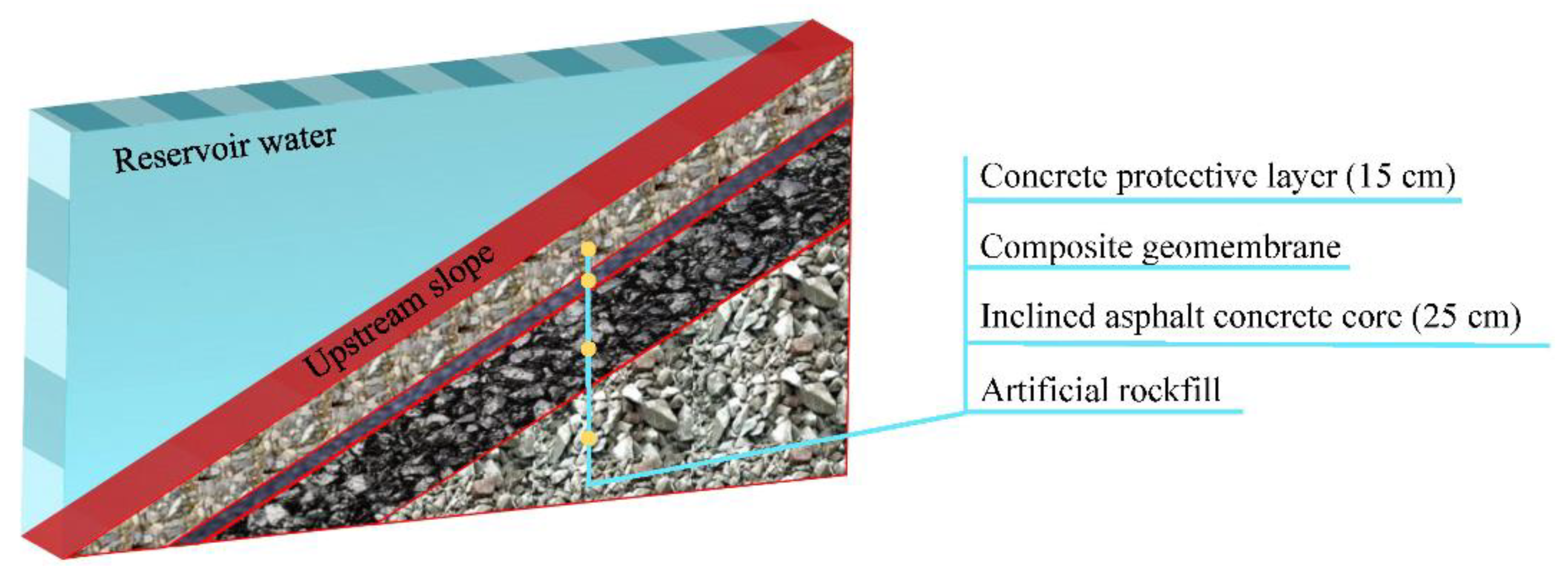
  • Seepage control in the dam body. On-site detection indicates that the density of the bottom blasting pile, whose porosity is less than that of the rockfill dam, is very high, but the density of the surface layer of the blasting pile is low [12]. In addition, after blasting, it is often necessary to heighten the dam body to the design elevation using artificial rockfill. However, in the early stage of artificial rockfill, large stones are used without rolling equipment, resulting in poor construction quality at the top of blast-fill dams. Therefore, in the design process, it is very important to select a reasonable seepage control measure in the dam body to accommodate the large, long-term and nonuniform deformation of blast-fill dams. At present, the most commonly used seepage control measure in dam bodies is an inclined core; inclined cores can be made of clay, asphalt concrete, composite geomembranes and other materials. Moreover, the support structures can be used to reduce the influence of deformation, such as concrete or stone protective layer, filter layer and transition layers. The seepage control measures in the dam body can also include curtain grouting, concrete cutoff wall construction and so on.
  • Seepage control in the peripheral joint. To satisfy the blasting requirements, the natural rock mass of a dam abutment is usually steep, which will cause a large change in the dam thickness at the joint between the dam foundation and dam body. There is a great possibility that the dam deformation will be uncoordinated, resulting in cracking of the impervious body, and that a seepage channel will be formed on the bedrock surface, threatening the dam safety. Therefore, seepage control measures should be carried out for the joint between the dam foundation and dam body, such as expanding the scope of the seepage control used in the dam body, using multilayer anti-seepage structures and selecting a flexible impervious body.

3.2. Reinforcement of Impervious Body

Affected by the large and nonuniform deformation during the operation period, the aging rate of impervious bodies of blast-fill dams is faster than that of other dams, especially for high blast-fill dams. After several years of operation, impervious bodies face many serious seepage problems, so reinforcement treatment is usually necessary for blast-fill dams. At present, most high blast-fill dams in China have been reinforced, and the statistics on the reinforcement measures of impervious bodies are shown in Table 2. Most blast-fill dams adopt flexible impervious bodies in the initial stage, such as inclined clay cores and IACCs. When the dam deformation tends to be stable, rigid impervious bodies, such as a concrete face and concrete cutoff wall, could also be used for reinforcement. Moreover, the Bailonghe blast-fill dam has been scrapped due to difficulties in reinforcement [24]. The Hujiashan blast-fill dam was not put into operation after blasting completion, and a concrete-face rockfill dam (CFRD), with a height of 63 m, was later built downstream. After 5 years of blasting, the impervious body of the Tangxian blast-fill dam, with a height of 70 m, was constructed by the geomembrane when the dam deformation was stable. At present, the Tangxian blast-fill dam has passed two flood peak tests, and the impervious body exhibits good operation performance. Based on the above analysis, it is known that the operation performance of an impervious body should be inspected and repaired in a timely manner. To reduce the possibility of impervious body damage, a first or second construction time of an impervious body could be selected at an appropriate time.

4. Operation Performance and Seepage Flow in the Impervious Body of a Blast-Fill Dam

To analyze the actual operation performance of blast-fill dams in detail, the design, reinforcement, operation performance and seepage control in the dam body of a typical blast-fill dam are investigated according to monitoring data, which are expected to serve as a reference for other dams with large deformation. The blast-fill dam is located in Western China and was built in 1970. The rock in the dam site is mostly gneissose granite. This blast-fill dam measures 85.00 m in height and 265.00 m in length, and its total reservoir capacity is 28.10 million m3. The topographic map and explosive layout before blasting are shown in Figure 1a, in which the left bank is the main blasting area and the right bank is the sub-blasting area. After blasting is completed, the blast-fill dam is completed by manually trimming the slope and heightening the dam body, as shown in Figure 1b. The average thickness of the overburden layer is 14~15 m, and most of the overburden layer is made up of cobbles and large erratic boulders. The slope ratio upstream is 1:1.70~1:2.25, and downstream is 1:1.85~1:2.00. The total dam volume is 2.08 million m3, of which the blasting pile is 1.44 million m3 and the artificial rockfill is 640 thousand m3. Blasting with a total weight of 1502 t created a pile volume of 2.36 million m3. The average height and lowest height of the blasting pile in the dam axis section are 57.30 m and 51.00 m, respectively, and the measured average porosity of the dam body is 24.5%. Due to the leakage problem, the dam was reinforced in 2000.

4.1. Structural Characteristic Analysis of Blast-Fill Dam Using the DEM

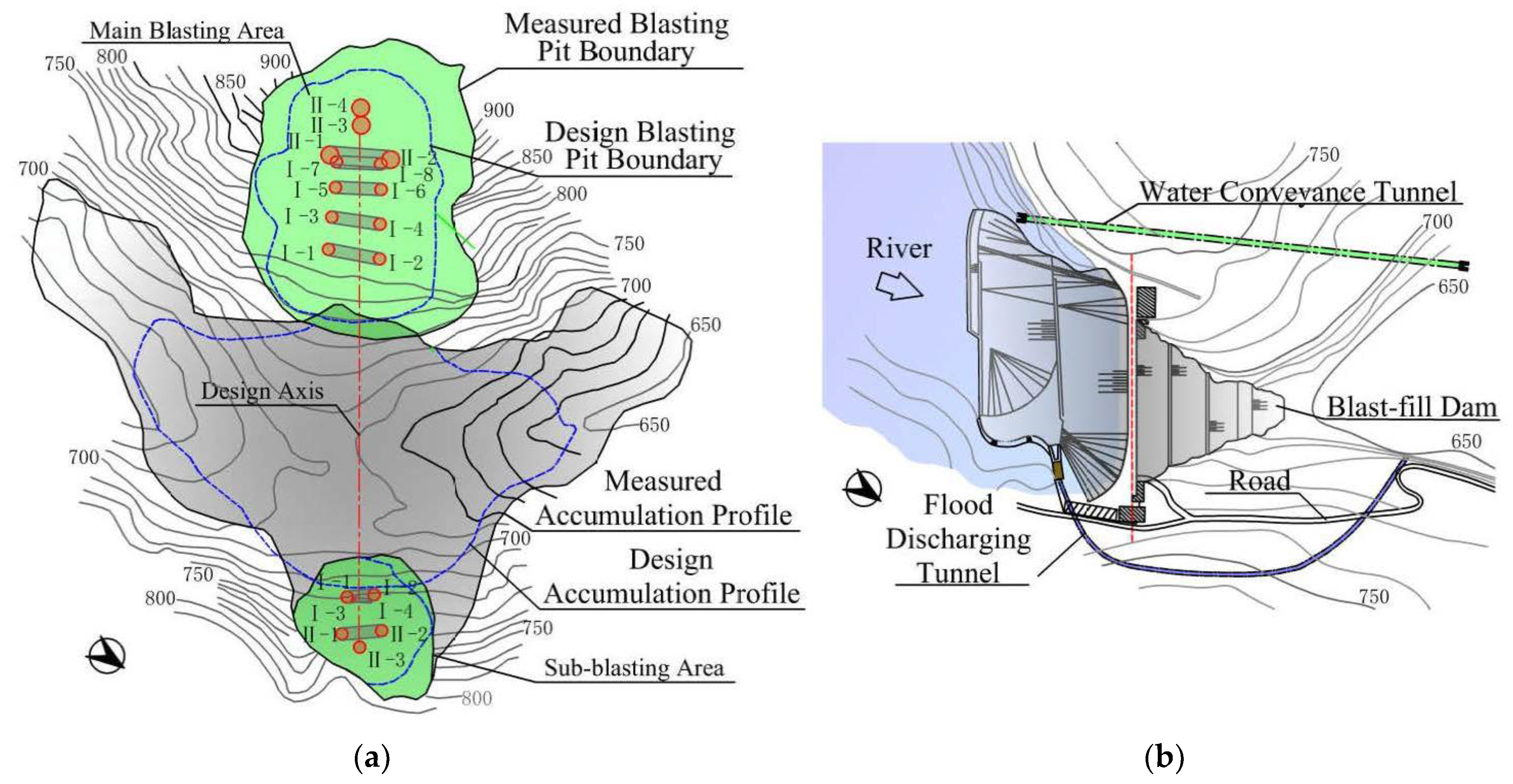
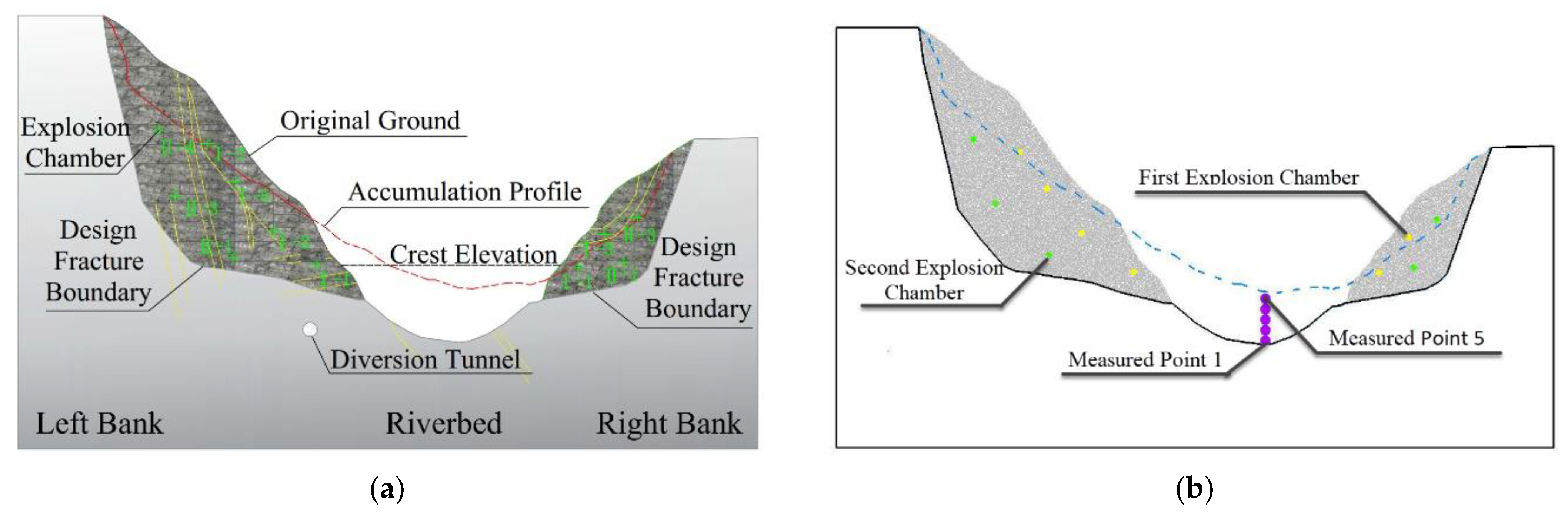
4.1.1. Discrete Element Simulation of Blasting Process

Due to the particular construction method of the blast-fill dam, the dam body formed by blasting has different dam structure characteristics from conventional rockfill dams, which has caused obvious changes in the operating environment of the impervious body. Therefore, it is necessary to study the structural characteristics of the blast-fill dam from the construction mode, laying a foundation for the failure reasons analyses of the impervious body. As a typical large deformation problem, directional blasting has a significant impact on the structural characteristics of blast-fill dams. However, conventional continuous numerical methods, such as the finite element method, cannot accurately simulate its blasting process [26,27]. Therefore, the DEM, a discontinuous numerical method [28,29], is used to simulate the blast-fill-dam-construction process in this paper. Then, the structural characteristics of the accumulation body are analyzed using monitoring data.
According to the geological profile and accumulation profile at the dam axis, shown in Figure 2a, the mountain rocks on both banks are hard gneiss granite, providing suitable directional blasting conditions. The explosion chambers’ layout adopts the spatial form of two rows, two columns and multiple layers with a two-stage initiation at a time interval of 2.07 s, including 12 chambers on the left bank, totaling 1325.02 t, and 7 chambers on the right bank, totaling 177.11 t. Therefore, a two-dimensional discrete element model of the directional blasting process simulation is constructed in Figure 2b. The size of this discrete element model is 530 m × 260 m (horizontal and vertical) with 15,525 stone particles. In order to explore the distribution law of compaction degree in the accumulation body, monitoring points are arranged in the riverbed, as shown in Figure 2b. Comprehensive related micromechanics research, the microparameters of the blast-fill dam, are used in Table 3.
The main essential technical factors in DEM simulations of the directional blasting process are as follows: (1) To improve the computational efficiency, the fracture boundary of blasting design is taken as the boundary of the discrete element model, while considering the rock mass characteristics on both banks of the dam site. The rear mountain is simulated by Wall, and the mountain in the blasting affected area is simulated by Ball. (2) The discrete element model will carry out equilibrium calculation under the initial gravity. The parallel bonding micro-contact model connects the Ball to simulate the original rock masses on both banks. (3) When the ratio of the maximum unbalanced force to the average unbalanced force is less than 10, it is considered that the blasting and its subsequent effects have entirely stopped, and the discrete element model is in a stable state. (4) According to the arrangement position of explosion chambers, the position of explosive particles in the discrete element model is determined. Then, the explosion load is simulated by expanding the radius of explosion point particles. Meanwhile, the explosion stress wave propagates outward from the explosion point in the spherical wave, which can be equivalent to the pulse stress wave and simplified to a triangular wave [30,31]. According to the above principle, the change process of the explosion stress wave can be transformed into the radius change law of explosion point particles. Therefore, the particle radius of the explosion point is obtained according to Formula (1), to apply the explosion load in the discrete element simulation.
r ( t ) = { 4 r max t / Δ T         0 t < 0.25 Δ T 4 3 r max ( t Δ T ) / Δ T         0.25 Δ T t < Δ T                 ( r max = r 0 + Δ r max = r 0 + 2 π r 0 P K n )
where t is the duration after initiation of blasting. Δ T is the action time of explosion load, taken as 10 ms in this paper [32,33]. r max is the maximum change in particle radius, which can be calculated according to the equality of the force on the rock wall around the explosion point and the explosion thrust. K n Δ r max = 2 π r 0 P . Here, r 0 is the original radius of particles, Δ r max is the maximum expansion amount of particles. The peak pressure P of rock mass around the explosion point can be calculated according to the coupled and uncoupled charge forms [34,35,36]. K n is the contact stiffness of particles in the discrete element model.
The whole blasting process simulated by the open-source DEM software Yade lasts 234.33 s and takes 32.4 h. The shape changes at the typical time are as follows. (1) After detonating the first set of explosion chambers, the blasting cavities are shown in Figure 3b. As shown in Figure 3c, the rock mass on the oblique upper side of the first blasting holes is broken and thrown into the air, forming a free face for the subsequent blasting. (2) After detonating the second set of explosion chambers, the rock mass in the blasting area is broken and thrown towards the riverbed, as shown in Figure 3d. (3) The equilibrium process after blasting is as shown in Figure 3e. The rocks thrown into the air gradually fall to the ground, and the unstable accumulations on both banks slide to the riverbed. (4) The final shape of blasting accumulation is shown in Figure 3f. The stacking line simulated by the DEM shows a good agreement with the field-measured results. Therefore, the discrete element simulation can accurately reflect the primary process and principle of blast-fill-dam construction, laying a foundation for the structural characteristic analysis of the blast-fill dam.

4.1.2. Structural Characteristic Analysis of the Blast-Fill Dam

As an essential index to evaluate the quality of rockfill, compaction is also the fundamental way to analyze the structural characteristics of the blast-fill dam. Therefore, during blasting, the change process of porosity and coordination number of monitoring points is shown in Figure 4. It can be seen from Figure 4 that: (1) In the vertical direction, the closer to the lower accumulation body, the more its compactness begins to increase first because of the different rockfill sources. The middle and lower parts of the accumulation body rapidly accumulate under the blasting effect, and the upper parts of the accumulation body are formed mainly by the constant balance adjustment. (2) The change curves of coordination number in the middle and lower parts of the accumulation body have a significant slope and a high peak value, indicating that their compactness increases rapidly, resulting in higher final compactness due to the explosion’s impact. At the same time, under the combined action of upper particles compaction, the final compactness of the middle and lower parts of the accumulation body will be further improved. (3) Compared with the middle and lower parts, the compactness of the upper part of the accumulation body is lower. The main reason is that most of the upper stones are freely rolled and accumulated along the slope, making it easy to form unconsolidated parts, such as voids. It should be noted that the concept of porosity in the DEM is different from that in actual engineering. Although its value cannot be directly equivalent to the actual porosity in engineering, its change trend is consistent with the actual porosity. Therefore, the porosity in the DEM can also be used to study the evolution and distribution law of the compactness of rockfill.
Through comprehensive analysis of the construction data, geotechnical tests and discrete element simulation results of blast-fill dams, it is considered that the blast-fill dam has the following structural characteristics compared with conventional rockfill dams. (1) The slope of a conventional rockfill dam is relatively regular under the action of manual construction. In contrast, the slope of the blast-fill dam presents a concave surface, which needs to be manually trimmed. (2) The gradation of conventional rockfill dams is sufficient under manual control, while the gradation of blasting accumulation is random, even though there is an overhead phenomenon locally. (3) The average porosity of this blast-fill dam is 24.5%; that of Shanba dam and Hujiashan dam in Yunnan, China, is less than 28%. Therefore, the average porosity of the blast-fill dam is equal to that of the rolling rockfill dam. However, the porosity of the middle and lower parts of the blast-fill dam is obviously smaller than the average porosity under the compaction of explosion impact force, which is more compact than that of conventional rolling rockfill dams. The porosity of the upper dam is obviously larger than the average porosity, so the compaction effect is poor. (4) Due to the continuous deformation of loose blasting rockfill and artificial rockfill at the top of the accumulation body, the blast-fill dam has long-term and uneven subsidence characteristics. (5) Different from the strong permeability of conventional rockfill dams, the permeability of blast-fill dams is affected by the density of the accumulation body and the content of fine materials. The permeability shows obvious differences in the dam body, leading to a higher local infiltration line behind the impervious body.

4.2. Seepage Cause Analysis and Impervious Body before and after Reinforcement

In the initial design stage, IACC is adopted for seepage control in the dam body, and a concrete cutoff wall with a maximum depth of 21.80 m is built in the riverbed. The top of the concrete cutoff wall is connected with the IACC, and its bottom part adopts curtain grouting. When the project was completed and put into operation, due to the cracks and collapse pits that formed in the IACC, a large seepage flow was observed repeatedly downstream. It is considered that the seepage control effect of this dam is poor, and the main reasons are as follows, according to the above discrete element simulation and analysis.
(1)
Long-term, large and nonuniform deformation of the dam body. Although there is a favorable compactness in the bottom blasting pile, the surface layer of the blasting pile, talus material of the dam foundation and artificial rockfill are relatively soft, causing nonuniform deformation on the inclined core foundation. Under high water pressure, the asphalt concrete strain exceeds its allowable value, forming cracks and, consequently, a seepage path.
(2)
Seepage path expansion. The reservoir water infiltrates through the cracks in the inclined core, and the cushion under the inclined core is gradually emptied, resulting in a larger zone of the inclined core hanging in the air. Finally, under high water pressure, the IACC breaks. Therefore, the complementary effects of seepage and collapse pits are observed: the cracks expand into the collapse pit, resulting in a significant increase in the amount of seepage.
(3)
Blasting pile erosion. Due to the damage in the inclined core, the hydraulic gradient and seepage deformation change in the dam body, aggravating the particle corrosion in the dam. Then, the rock body that has been stabilized in the dam begins to slide, rearrange and collapse, which will cause collapse and damage to the inclined core and cushion.
Due to water storage, the asphalt concrete had been damaged several times, causing seepage. Subsequently, the crack and collapse pits in the IACC were repaired and reinforced. The main engineering measures include the following: (1) Strengthening the IACC foundation. To improve the foundation density of the inclined core, the IACC foundation was filled with grout. (2) A composite geomembrane was laid on the IACC to strengthen the seepage control effect in the dam body. (3) At the interface between the upstream face and dam abutment, an expansion joint is set to prevent the dam body from being pulled and cracked. The seepage control measures for the dam body after reinforcement are shown in Figure 5.

4.3. Operation Performance Analysis after Reinforcement Using Measured Data

In terms of reinforcement, the inclined core foundation is filled with grouting, and a composite geomembrane is laid on the inclined core to improve the seepage control ability of the dam body. After the reinforcement was added, this blast-fill dam passed several tests of high water levels, and no large collapse pits or seepage was observed. Hence, the overall operation of this blast-fill dam is stable. To clarify the operation performance of blast-fill dams after reinforcement, the seepage control effect of the geomembrane and IACC and the change in phreatic line are analyzed in this paper, based on monitoring data.

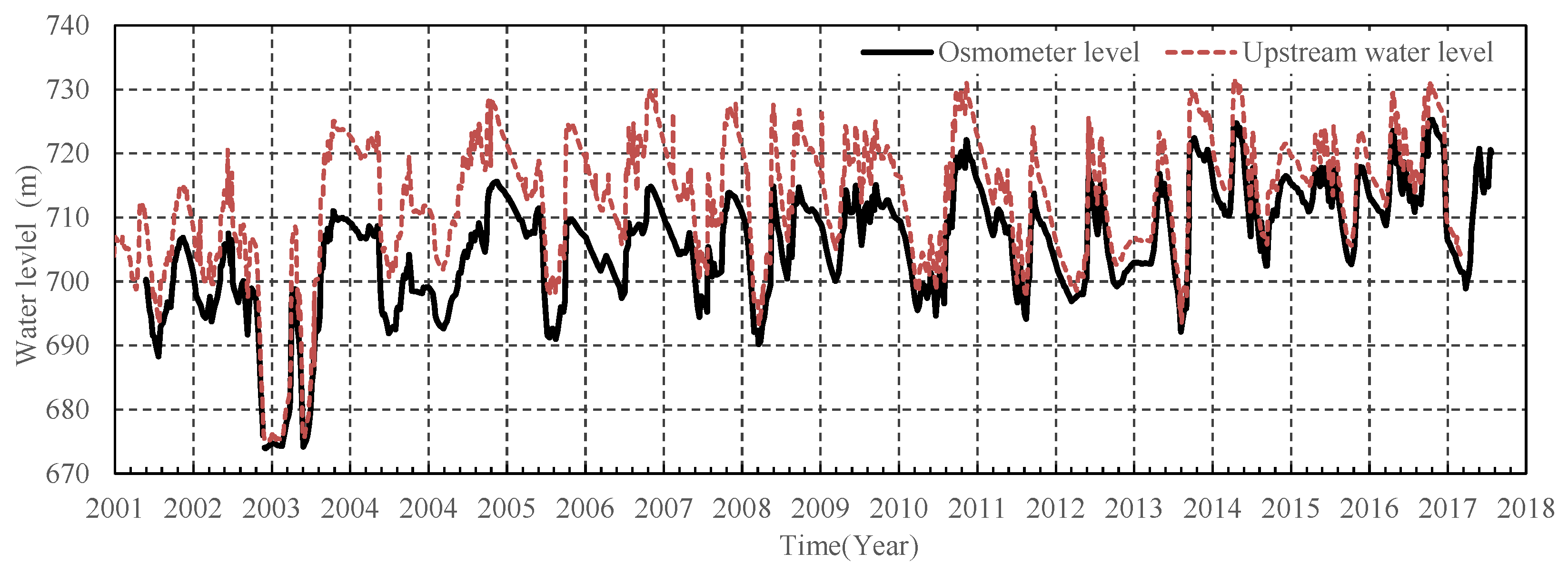
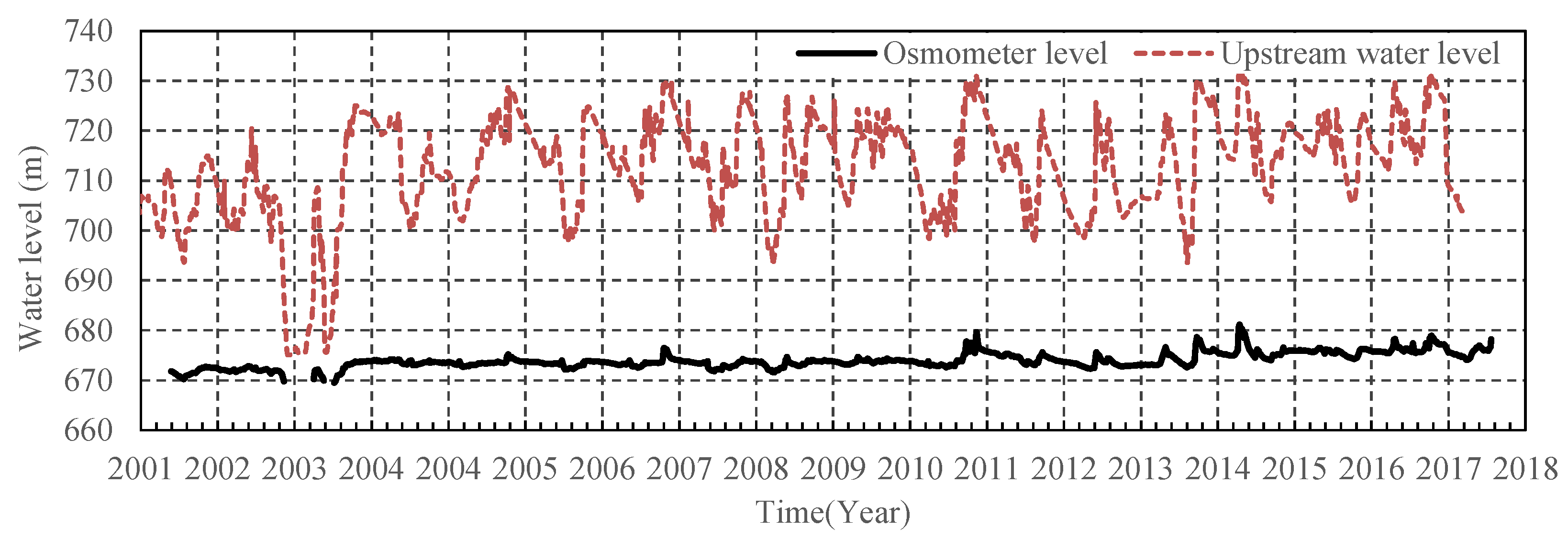
4.3.1. Seepage Control Effect of the Geomembrane

To elucidate the performance of the geomembrane, the B10 and B11 osmometer observation points are installed behind the geomembrane in the middle of the upstream face, and the B2 and B9 observation points are fixed at the bottom of the upstream face. The hydrographs of the osmometer level and upstream water level of B10 and B11 are shown in Figure 6 and Figure 7, respectively. From the monitoring start date, the osmometer level of these two points is very close to the upstream water level, and the water level difference remains within 0.5 m. Therefore, there is no hysteresis characteristic at B10 and B11, indicating that the seepage control effect of the geomembrane at B10 and B11 is weak. It is inferred that the local geomembrane at B10 and B11 has been destroyed, and some possible reasons for this inference are as follows: (1) Since the osmometer level is similar to the upstream water level from the monitoring start date, it is highly likely that the geomembrane near B10 and B11 was destroyed during the construction period. (2) According to the measured deformation data and calculation results from finite element method simulations, the central part of the upstream surface, where the two observation points are located, undergoes a relatively large deformation. The large deformation causes the local geomembrane to lose its strength and local cracking to occur under the resulting water pressure. The measured deformation data show that the cumulative deformations of the 3-4 and 4-4 observation points are 55 mm and 116 mm, respectively, after reinforcement. The 3-4 and 4-4 observation points are in the same cross section as B10, and the height difference between them is less than 7 m. Moreover, the 3-6 and 4-6 deformation observation points are in the same cross section as B11, and the height difference between them is less than 6 m. The cumulative deformations of 3-6 and 4-6 are 115 mm and 245 mm, respectively, and 4-6 has the maximum deformation after reinforcement throughout the dam. In addition, according to the results of the finite element method, the maximum value of the third principal stress of the geomembrane occurs in the central part of the upstream face, which is very close to the positions of B10 and B11. In summary, it can be determined that the local geomembrane at B10 and B11 has been destroyed.
The hydrographs of the osmometer level and the upstream water level of the B2 and B9 observation points behind the geomembrane are shown in Figure 8 and Figure 9, respectively. B2 and B9 are located in the joint between the cutoff wall and the geomembrane, in the bottom of the dam body and the central part of the riverbed. Figure 8 and Figure 9 show the following results: (1) The osmometer levels of B2 and B9 are consistently lower than the upstream water level, and the maximum differences in the water levels at these points are 17.05 m and 15.26 m, respectively, indicating that the geomembrane at the bottom of the dam body has a certain seepage control effect. (2) The annual statistics of the osmometer levels of B2 and B9 under the high water level are shown in Table 4. The reduction water level (the difference between the osmometer level and the upstream water level) shows a decreasing trend year on year, indicating that the seepage control effect of the geomembrane at the bottom of the dam body is deteriorating. The reasons for the weakening of the seepage control effect at B2 and B9 are as follows: (1) According to the analysis results of B10 and B11, the geomembrane in the central part of the upstream face has been partially destroyed, resulting in seepage through the geomembrane, affecting the measurements at B2 and B9. (2) B2 and B9 are located at the bottom of the dam body, an area that is subject to high water pressure for a long time. Therefore, the local geomembrane at B2 and B9 gradually ages, and the seepage control effect deteriorates.

4.3.2. Seepage Control Effect of the IACC

To elucidate the performance of the IACC, the B1, B3, B6 and B7 osmometer observation points are installed behind the inclined core. The observation data show that the osmometer level behind the IACC is continuously stable and low. B3 is taken as an example, for which the hydrograph of the osmometer level and the upstream water level is shown in Figure 10: (1) The osmometer level of B3 fluctuates within 669.48~680.88 m, according to the upstream water level, and the average annual osmometer level of B3 is 674.30 m. (2) In recent years, the osmometer level behind the inclined core has gradually increased. B9 and B3 are located behind the geomembrane (in front of the inclined core) and behind the inclined wall, respectively, within the same cross section. Therefore, the reduction water level (the difference in osmometer level between B9 and B3) of B3 can clearly reflect the seepage control effect of the IACC, as shown in the Table 4. With the gradual weakening of the seepage control effect of the geomembrane, the IACC took on more seepage control functionality. Hence, the reduction water level of the IACC is increasing year on year, and the osmometer level behind the inclined core still exhibits a certain rise. According to the above analysis, the IACC is still the main measure for seepage control in this dam, whose seepage control effect is stable.
To compare the seepage control effect of different impervious bodies, the reduction water levels of the geomembrane and IACC are calculated according to the upstream reservoir water level and the osmometer level of B9 and B3. The hydrographs of the seepage effects under high water levels in each year are shown in Table 4 and Figure 11. (1) According to B9, at the bottom of the dam body, the reduction water level of the geomembrane is approximately 10 m, showing a very clear decreasing trend in recent years. (2) The seepage control effect of the IACC remains stable, and the reduction water level of the IACC is approximately 40 m, showing a slight increasing trend with the weakening of the geomembrane in recent years. Therefore, in this blast-fill dam, the ratio of the seepage control abilities of the IACC and the geomembrane is approximately 4:1, and the IACC is still the main measure for seepage control. In addition, with aging, the seepage control effect of the geomembrane will further reduce.

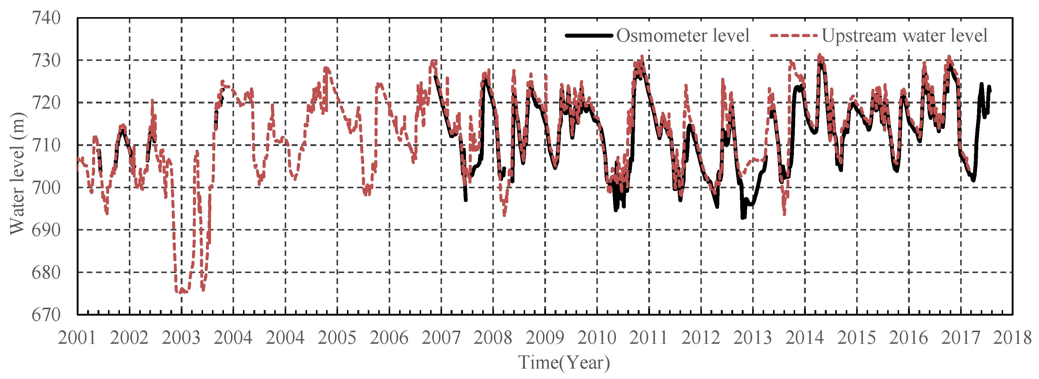
4.3.3. Analysis of Phreatic Line

According to the osmometer observation points B11, B7, #1 and #2, the phreatic line in this blast-fill dam is inferred, as shown in Figure 12. The phreatic line in the blast-fill dam is slightly higher than that of the CFRD. In the dam body of CFRD, the seepage can be immediately drained due to a large gap in the rockfill area, so the phreatic line behind the impervious body is basically level with the downstream water level. The reasons why the phreatic line of the blast-fill dam is high are as follows:
(1)
Due to this blast-fill dam having several large leaks, the fine particles were transported from upstream to downstream by seepage in the dam body. Hence, the rockfill pores in the downstream area of the dam are filled, and the permeability of this blast-fill dam is reduced, which is not conducive to the dissipation of seepage and pore water. Therefore, the phreatic line and overflow position of this blast-fill dam are raised.
(2)
According to the on-site detection of multiple blast-fill dams [12,37], the gradation of the bottom blasting pile is uniform, and its compactness exceeds or equals that of other rockfill dams [38,39]. On the one hand, during the blasting process, the rock mass experienced short-term high-speed impact, crushing, thrusting, collision and stacking, which had a considerable tamping effect on the dam foundation and blasting pile. On the other hand, the rock mass is mixed with surface soil in the bank slope and talus material and overburden in the dam foundation, so the rockfill pores are filled with fine materials, forming a dam with continuous gradation and high compactness. Therefore, the bottom of the blast-fill dam has certain impermeability due to the continuous gradation and high compactness, causing an obvious lifting effect on the phreatic line of blast-fill dams.
(3)
Because this dam once temporarily stored water before the impervious body was completed, it is possible that fine particles were transported from upstream to downstream. Then, the rockfill pores downstream were blocked by fine materials, and the phreatic line rose. According to the monitoring data, after reinforcement, the measured seepage flow was 0.00~0.20 m3/s. If the average seepage flow of this blast-fill dam is calculated as 0.04 m3/s, the annual seepage flow accounts for 6.54% of the total reservoir capacity, indicating that the overall seepage flow of this blast-fill dam is normal. Because of the large occlusal force between rockfill materials, a slightly higher phreatic line has a small impact on the slope stability of blast-fill dams, but osmometer monitoring should be further strengthened.
The above analysis shows that the geomembrane of this blast-fill dam has a certain seepage control effect but is partially damaged and has a tendency to deteriorate under the influence of construction, operation and aging. Limited by the number of observation points behind the geomembrane, it is impossible to comprehensively discriminate the overall operation performance of the geomembrane. In addition, the IACC exhibits a certain adaptability to the large dam deformation due to its flexible characteristics. Currently, the IACC is stable, which is still the main measure for seepage control. The measured phreatic line in the dam is slightly higher than those of other rockfill dams, but the influence of the phreatic line on the slope stability and dam safety is small. The seepage flow of this blast-fill dam is normal. Therefore, after reinforcement, the overall operation performance of this blast-fill dam has been normal, but monitoring should be further strengthened because of the geomembrane deterioration.
Blast-fill dams have many obvious advantages, but their long-term and large deformation in the operation period strains the seepage control system. Based on the design experience and operation performance of this blast-fill dam, we can conclude that a flexible impervious material should be selected for reinforcement to adapt to the deformation of blast-fill dams in the design stage, and the secondary treatment of impervious bodies can be considered when the dam deformation is stable. In addition, the impervious body should be inspected and repaired in a timely manner to avoid further damage.

5. Conclusions

Through collecting data on blast-fill dams, the characteristics and development trends of blast-fill dams were analyzed. Then, the design requirements and the reinforcement situation of blast-fill dams in China were reviewed. Subsequently, for a typical blast-fill dam, the operation performance and seepage flow of the geomembrane and the IACC, before and after reinforcement, were investigated using the DEM and measured data. The cause of the slightly higher phreatic line in blast-fill dams was explained. The porosity of the middle and lower parts of the blast-fill dam are obviously more compact than those of a conventional rolling rockfill dam under the compaction of explosion impact. Due to the continuous deformation of loose blasting rockfill and artificial rockfill at the top of the accumulation body, the blast-fill dam has long-term and uneven subsidence characteristics. According to the above analysis, for the dam type that undergoes large deformation in the operation period, a first or secondary treatment of the impervious body could be considered to avoid damage to the impervious body for risk reduction. A flexible material that can adapt to a large deformation should be selected as an impervious body, and the impervious body should be inspected and repaired in a timely manner. The monitoring and analysis work should be strengthened. The design requirements and reinforcement measures of the seepage control system of blast-fill dams are also applicable to other dams with large deformation for risk reduction, such as high rockfill dams, soft-rock dams and abandoned slag dams, and have a certain significance as a reference for the treatment of landslides and confined lakes.

Author Contributions

C.M.: Conceptualization, Methodology, Software, Writing—Original Draft; Z.G.: Validation, Visualization, Writing—Review and Editing; J.Y.: Supervision, Funding acquisition, Project administration; L.C. (Lin Cheng): Resources, Formal analysis; L.C. (Lei Chen): Investigation, Data curation. All authors have read and agreed to the published version of the manuscript.

Funding

This research was funded by the Key Projects of Natural Science Basic Research Program of Shaanxi Province grant number (2018JZ5010), the Water Science Plan Project of Shaanxi Province grant number (2018SLKJ-5) and Joint Funds of Natural Science Fundamental Research Program of Shaanxi Province of China and the Hanjiang-to-Weihe River Valley Water Diversion Project grant number (2019JLM-55).

Acknowledgments

The authors are grateful to Lei Lv for the data about the blast-fill dam.

Conflicts of Interest

The authors declare no conflict of interest.

References

  1. Wang, X.G. Discussion on some problems observed in high earth-rockfill dams. Chin. J. Geotech. Eng. 2018, 40, 203–222. (In Chinese) [Google Scholar] [CrossRef]
  2. Ma, C.H.; Yang, J.; Zenz, G.; Staudacher, E.J.; Cheng, L. Calibration of the microparameters of the discrete element method using a relevance vector machine and its application to rockfill materials. Adv. Eng. Softw. 2020, 147, 102833. [Google Scholar] [CrossRef]
  3. Maranha, D.N.E. Advances in Rockfill Structures; NATO ASI Series E: Applied Science; Springer: Berlin/Heidelberg, Germany, 1991; pp. 13–16. [Google Scholar]
  4. Jiang, G.C. Review on development of geotechnical engineering research in the past 50 years. J. China Inst. Water Resour. Hydropower Res. 2008, 6, 16–26. (In Chinese) [Google Scholar] [CrossRef]
  5. Qlz, A.; Ygh, B.; Msl, B.; Dyl, A. Role of negative pressure in structural responses of gravity dams to underwater explosion loadings: The need to consider local cavitation. Eng. Fail. Analysis 2021, 122, 105270. [Google Scholar] [CrossRef]
  6. Meng, N.; Bai, J.; Chen, Y.; Wang, X.; Wu, B. Stability analysis of roadside backfill body at gob-side entry retaining under combined static and dynamic loading. Eng. Fail. Anal. 2021, 127, 105531. [Google Scholar] [CrossRef]
  7. Adushkin, V.V. Russian Experience with Blast-Fill Dam Construction. Natural and Artificial Rockslide Dams; Springer: Berlin/Heidelberg, Germany, 2011; pp. 104–106. [Google Scholar]
  8. Nedriga, V.P.; Pokrovskii, G.I.; Avdeev, F.A. Earth dams constructed by the directional blasting method. Hydrotech. Constr. 1986, 20, 61–66. [Google Scholar] [CrossRef]
  9. Pokrovskii, G.I.; Lushnov, N.P. Technology of constructing blast-filled dams and geotechnical properties of soils of such structures. Hydrotech. Constr. 1992, 26, 395–400. [Google Scholar] [CrossRef]
  10. Havenith, H.B.; Torgoev, I.; Torgoev, A.; Strom, A.; Xu, Y.; Fernandez-Steeger, T.M. The Kambarata 2 blast-fill dam, Kyrgyz Republic: Blast event, geophysical monitoring and dam structure modelling. Geoenvironmental Disasters 2015, 2, 11. [Google Scholar] [CrossRef] [Green Version]
  11. Torgoev, I.A.; Havenith, H.B.; Torgoev, A.D. Geophysical Monitoring of Artificial Landslide Dam of Kambarata Hydro Power Plant-2 (Kyrgyzstan); Springer: Berlin/Heidelberg, Germany, 2014; pp. 11–13. [Google Scholar]
  12. Chen, B.L.; Wang, B.Q.; Chen, Y.Z. Structural and seepage characteristics of rockfill dam by directional blasting. J. Hydraul. Eng. 1998, 29, 51–56. (In Chinese) [Google Scholar] [CrossRef]
  13. Xi, H.Z.; Pan, J.N.; Wang, C.Y. Soil clogging to seal the rockfill dam constructed by directional blasting. J. Hydraul. Eng. 1992, 4, 8–14. (In Chinese) [Google Scholar] [CrossRef]
  14. Adushkin, V.V. Explosive initiation of creative processes in nature. Combust. Explos. Shock Waves 2000, 36, 695–703. [Google Scholar] [CrossRef]
  15. Yan, Y.Z.; Yuan, J.G. New construction technology for gully harness key engineering soil conservation. J. Hydraul. Eng. 2002, 33, 78–81. (In Chinese) [Google Scholar] [CrossRef]
  16. Evans, S.G.; Delaney, K.B.; Hermanns, R.L.; Strom, A.; Scarascia-Mugnozza, G. The formation and behaviour of natural and artificial rockslide dams; implications for engineering performance and hazard management. Chin. Med. J. 2011, 66, 1046–1055. [Google Scholar] [CrossRef]
  17. Honkanadavar, N.P.; Sharma, K.G. Testing and Modeling the Behavior of Riverbed and Blasted Quarried Rockfill Materials. Int. J. Geomech. 2014, 14, 04014028. [Google Scholar] [CrossRef]
  18. Lu, J.H.; Tan, J.X.; Zhou, H.Q. Review of the illness characteristics and reinforcement technology of directed blasting rockfill dams. Hydropower New Energy 2017, 10, 10–12, 26. (In Chinese) [Google Scholar] [CrossRef]
  19. Sokolov, Y.F.; Shapovalov, G.I. Building a rockfill dam by directional blasting. Hydrotech. Constr. 1968, 2, 385–389. [Google Scholar] [CrossRef]
  20. Huo, Y.J. Research on high directional blasting dam technology. Water Power 1991, 9, 71–75. (In Chinese) [Google Scholar]
  21. Li, Z.; Wang, T.; Ge, W.; Wei, D.; Li, H. Risk analysis of earth-rock dam breach based on dynamic bayesian network. Water 2019, 11, 2305. [Google Scholar] [CrossRef] [Green Version]
  22. Wang, X.G. Typical Blasting Engineering and Technology in China; Metallurgical Industry Press: Beijing, China, 2006; pp. 55–57. (In Chinese) [Google Scholar]
  23. Xie, L.A. Application of directional blasting in construction of rockfill dam. Water Power 1987, 4, 60–63. (In Chinese) [Google Scholar]
  24. Li, Z.X. The first scrapping demonstration of the blast-fill dam reservoir in Yunnan Province. China Water Resour. 2011, 4, 57–58. (In Chinese) [Google Scholar] [CrossRef]
  25. Yang, N.H.; Zhao, X.B. Preliminary study on soil erosion control with technology of building dam with directional blasting. Enigneering Blasting 1998, 4, 34–38. (In Chinese) [Google Scholar]
  26. Labra, C.; Onate, E.; Zarate, F.; Rojek, J.; Yaseen, Z.M. Modelling and Simulation of the Effect of Blast Loading on Structures Using an Adaptive Blending of Discrete and Finite Element Methods. In Proceedings of the 2nd International Conference on Particle-Based Methods—Fundamentals and Applications (Particles), Barcelona, Spain, 2 September 2011. [Google Scholar] [CrossRef] [Green Version]
  27. An, H.M.; Liu, H.Y.; Han, H.; Zheng, X.; Wang, X.G. Hybrid finite-discrete element modelling of dynamic fracture and resultant fragment casting and muck-piling by rock blast. Comput. Geotech. 2017, 81, 322–345. [Google Scholar] [CrossRef]
  28. Yan, C.Z.; Tong, Y.; Luo, Z.Q.; Ke, W.H.; Wang, G. A two-dimensional grouting model considering hydromechanical coupling and fracturing for fractured rock mass. Eng. Anal. Bound. Elem. 2021, 133, 385–397. [Google Scholar] [CrossRef]
  29. Ma, C.H.; Gao, Z.Y.; Yang, J.; Cheng, L.; Zhao, T.H. Calibration of Adjustment Coefficient of the Viscous Boundary in Particle Discrete Element Method Based on Water Cycle Algorithm. Water 2022, 14, 439. [Google Scholar] [CrossRef]
  30. Afrasiabian, B.; Ahangari, K.; Noorzad, A. Study on the effect of air deck on ground vibration and development of blast damage zone using 3D discrete element numerical method. Arab. J. Geosci. 2021, 14, 1267. [Google Scholar] [CrossRef]
  31. Masi, F.; Stefanou, I.; Maffi-Berthier, V.; Vannucci, P. A Discrete Element Method based-approach for arched masonry structures under blast loads. Eng. Struct. 2020, 216, 110721. [Google Scholar] [CrossRef]
  32. Gao, W.L.; Zhang, Z.H.; Li, B.J.; Li, K.P. Study on numerical simulation of geometric elements of blasting funnel based on pfc5.0. Shock Vib. 2021, 11, 8812964. [Google Scholar] [CrossRef]
  33. He, C.; Yang, J. Experimental and numerical investigations of dynamic failure process in rock under blast loading. Tunn. Undergr. Space Technol. 2019, 83, 552–564. [Google Scholar] [CrossRef]
  34. Saharan, M.R.; Mitri, H.S. Numerical procedure for dynamic simulation of discrete fractures due to blasting. Rock Mech. Rock Eng. 2008, 41, 641–670. [Google Scholar] [CrossRef]
  35. Babanouri, N.; Abdolahpour, M.; Dehghani, H. Modeling blast-induced fragmentation of jointed rock mass using voronoi discrete-element method. Int. J. Geomech. 2020, 20, 04020117. [Google Scholar] [CrossRef]
  36. Babanouri, N.; Mansouri, H.; Nasab, S.K.; Bahaadini, M. A coupled method to study blast wave propagation in fractured rock masses and estimate unknown properties. Comput. Geotech. 2013, 49, 134–142. [Google Scholar] [CrossRef]
  37. Huang, Y.Q. The development of directional blasting and dam construction in China. Blasting 1984, 2, 3–7. (In Chinese) [Google Scholar]
  38. Liu, D.H.; Sun, L.F.; Ma, H.Y.; Cui, W. Process simulation and mesoscopic analysis of rockfill dam compaction using discrete element method. Int. J. Geomech. 2020, 20, 04020047. [Google Scholar] [CrossRef]
  39. Ameen, A.; Ibrahim, Z.; Othman, F.; Al-Ansari, N.; Yaseen, Z.M. Minimizing the principle stresses of powerhoused rock-fill dams using control turbine running units: Application of finite element method. Water 2018, 10, 1138. [Google Scholar] [CrossRef] [Green Version]
Figure 1. Comparison before and after construction of the blast-fill dam: (a) layout of explosion chambers and topographic map before blasting; (b) layout of the completed project.
Water 14 01443 g001
Figure 2. 2D discrete element model of the directional blasting process: (a) geological profile at dam axis; (b) discrete element model of blasting.
Water 14 01443 g002
Figure 3. Typical process of discrete element simulation of directional blasting: (a) 0.000 s; (b) 0.003 s; (c) 0.200 s; (d) 2.090 s; (e) 50.000 s; (f) 51.2 s.
Water 14 01443 g003
Figure 4. Compaction change of accumulation after blasting: (a) coordination; (b) porosity.
Water 14 01443 g004
Figure 5. Anti-seepage structure after reinforcement of a blast-fill dam.
Water 14 01443 g005
Figure 6. The hydrograph of the upstream water level and osmometer level of B10.
Water 14 01443 g006
Figure 7. The hydrograph of the upstream water level and osmometer level of B11.
Water 14 01443 g007
Figure 8. The hydrograph of the upstream water level and osmometer level of B2.
Water 14 01443 g008
Figure 9. The hydrograph of the upstream water level and osmometer level of B9.
Water 14 01443 g009
Figure 10. The hydrograph of the upstream water level and osmometer level of B3.
Water 14 01443 g010
Figure 11. Comparison of the seepage control effects between the geomembrane and IACC.
Water 14 01443 g011
Figure 12. The phreatic line of the blast-fill dam.
Water 14 01443 g012
Table 1. Statistics on the main blast-fill dams.
No.ProjectLocationBlasting TimeDam HeightDam
Volume
(×104 m3)
Impervious Body TypeRemarks
1ChirchiqSoviet Union1935 -First worldwide,
river closure
2Alma-AtaSoviet Union (Kazakhstan)1966~
1967
150.0237.0NoneMultiple blasting,
controlled mudslides
3BaipazaSoviet Union (Tajikistan)196965.078.0 Impervious body built by blasting
4Ak-SuSoviet Union197191.025.0None
5BurlykiaSoviet Union (Kyrgyzstan)197550.054.0None
6Uch-TerekSoviet Union (Kyrgyzstan)198942.087.0None
7Kambarata IIKyrgyzstan200960.0 Concrete face
8Dong HuanHebei, China195933.58.5Inclined clay coreFirst in China,
dam break
9Shi Kuo IZhejiang, China195952.018.4Inclined clay core
10Nan ShuiGuangdong, China196081.8100.0Inclined clay coreMaximum reservoir capacity in China
11He JiapingHebei, China195940.03.4None
12Fu XiZhejiang, China196050.017.7Inclined clay core
13Nan ShanZhejiang, China196056.05.2
14Tao ShupingHebei, China196140.04.7NoneDam break
15Shi BianyuShaanxi, China197385.0143.7IACC
16Li CeyuShanxi, China197551.626.30IACC
17Hong YanYunnan, China197655.054.0IACC
18Hu JiashanYunnan, China197660.038.0IACC
19Shan BaYunnan, China197740.013.2Hydraulic fill
20Ma LucaoYunnan, China197740.014.6Inclined clay core
21Yi YiYunnan, China197790.0120.0None
22Kang JiaheYunnan, China197870.032.5Plastic film
23Bai LongheYunnan, China197846.020.0Inclined clay core
24Tang XianGuangxi, China199970.0 Geomemb-raneImpervious body built after 5 years
25Shui MenHebei, China1960-0342.06.2-Tailings dam
26E KouShanxi, China197265.530.7-Tailings dam
27Liu JiagouShaanxi, China200240.09.1-Tailings dam
28Sai ShentangQinghai, China200236.412.1-Tailings dam
29Mu XingouShaanxi, China200662.042.2-Tailings dam
30Da ShibangouShaanxi, China201035.08.5-Tailings dam
31Xin KangSichuang, China198550.020.0-Soil and water conservation
32Hu DonggoShanxi, China199219.32.5-Soil and water conservation
33Ma DihaoNeimenggu, China199233.03.8-Soil and water conservation
34Qia PuqihaiXinjiang, China2002 0.5 River closure
Table 2. The statistics on the reinforcement of blast-fill dams in China.
No.ProjectDam HeightBlasting TimeInitial DesignReinforce-Ment TimeReinforcement Design
1Fu Xi50.01960Inclined clay core2009Concrete face
2Shi Bianyu85.01973IACC1999Geomembrane
3Li Ceyu51.61975IACC Thickened face
4Yi Yi90.01977None2007Concrete diaphragm wall
5Ma Lucao40.01977Inclined clay core2010Concrete diaphragm wall
6Shan Ba40.01977Hydraulic fill2004Concrete diaphragm wall
7Kang Jiahe70.01978Plastic film2010Curtain grouting
8Hu Jiashan60.01976IACC2010New CFRD
9Bai Longhe46.01978Inclined clay core1997Reinforcement failed, discard
Table 3. Microparameters of the blast-fill dam.
ParameterUnitValue
Particle densitykg/m32500.0
Friction coefficient (ball-ball)-0.1
Effective contact modulusGPa50.0
Normal-to-shear stiffness ratio-2.0
Bond effective modulusGPa10.0
Bond normal-to-shear stiffness ratio-1.0
Parallel-bond tensile strengthMPa37.0
Parallel-bond cohesionMPa37.0
Parallel-bond friction angleDegree10.0
Table 4. Osmometer levels of B2, B9 and B3 under high water levels in each year.
TimeUpstream Water LevelPoints Behind GeomembranePoint Behind IACC
B2B9B3
Osmometer LevelReduction Water LevelOsmometer LevelReduction
Water Level
Osmometer LevelReduction Water Level
23 October 2005728.32714.0914.23715.1813.14674.6640.52
25 October 2006724.78707.7317.05709.7815.00673.935.88
27 October2007729.78713.6316.15714.5215.26675.6338.89
30 November 2008727.70712.1415.56712.7714.93673.7139.06
25 May 2009727.58713.4714.11714.8812.70674.7140.17
12 September 2010724.97713.9311.04715.079.90674.3140.76
9 November 2011731.08721.509.58722.089.00679.4642.62
16 September 2012723.37713.2310.14713.779.60675.6238.15
30 May 2013725.66717.038.63717.448.22675.6341.81
4 October 2014729.82721.778.05722.427.40678.1444.28
24 April 2015731.21723.287.93724.027.19676.4947.53
18 April 2017729.62722.926.70723.556.07678.2845.27
10 October 2017730.91724.256.66725.215.70678.7246.49
Publisher’s Note: MDPI stays neutral with regard to jurisdictional claims in published maps and institutional affiliations.

