Article

Novel Techniques to Study the Effect of Parapet Wall Geometry on the Performance of Piano Key Weirs

1
Civilian Engineering Techniques Department, Southern Technical University (STU), Nassiryah 64001, Iraq
2
Department of Civil Engineering, Faculty of Engineering, Universiti Putra Malaysia (UPM), Serdang 43400, Malaysia
3
College of Engineering, University of Basrah, Basrah 61004, Iraq
*
Authors to whom correspondence should be addressed.
Water 2023, 15(13), 2307; https://doi.org/10.3390/w15132307
Submission received: 23 May 2023 / Revised: 14 June 2023 / Accepted: 16 June 2023 / Published: 21 June 2023
(This article belongs to the Section Hydraulics and Hydrodynamics)

Abstract

:
Piano key weirs (PKWs) with crown parapet walls effectively manage water levels and maximize storage. However, their efficiency is compromised by interactions between water flow and submerged outlets during rising water levels. This study investigates novel parapet wall designs to improve PKW performance and reduce submergence effects. The experiment focuses on a PKW with a fixed 12.6 cm weir height. Three parapet wall configurations are tested: Mode 1 (walls on all apex), Mode 2 (walls fixed on sides and inlet), and Mode 3 (walls along the sides). Each mode includes three parapet wall profiles: rectangular (consistent form), triangular, and trapezoidal (varying characteristics). Results indicate that parapet wall design significantly affects water level variations with increasing wall height. Mode 3, featuring triangular and trapezoidal parapet walls, demonstrates the highest discharge capacity among the examined profiles. The discharge coefficient correlates with parapet wall height and form. Notably, the triangular wall in Mode 3 outperforms Modes 1 and 2 when parapet walls maintain an R/P ratio of 0.36. This study introduces innovative parapet wall designs to enhance PKW efficiency. By implementing advanced configurations, significant improvements in water control and discharge capacity can be achieved. These findings contribute to the state-of-the-art in PKW technology and offer valuable insights for practical engineering applications.

1. Introduction

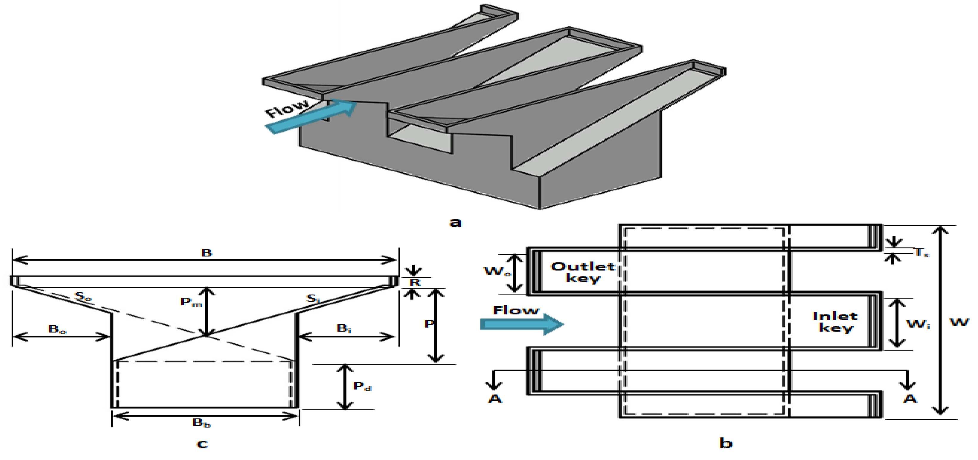
Due to the ongoing impacts of climate change, the intensities of potential extreme storm events have escalated, posing a potential risk to the safety of existing dams. Numerous dams and spillways are presently deemed inadequate in size and require either replacement or rehabilitation. Weirs are a frequently encountered hydraulic feature that is present in waterways and is integrated into dams and embankments [1]. Weirs have two distinct categories, namely, linear and nonlinear. Linear weirs have a limited ability to release water, which is one of their major drawbacks. If increasing the reservoir’s water volume is not possible due to limitations, the reservoir’s discharge capacity can be increased in three ways: increasing the width of the spillway, reducing the elevation of the spillway, and replacing the linear weir with a nonlinear (labyrinth) weir until the weir reaches a predetermined footprint size [2]. But, it is not advisable to decrease the elevation of the spillway crest, as this would result in a reduction in the normal pool level and subsequently diminish the storage capacity of the reservoir [3]. Labyrinth weirs, which have vertical walls instead of horizontal ones, outperform linear spillways. Although labyrinth weirs have a simple geometry and a simple design, they cannot be placed with concrete dams due to their huge footprint sizes. This type of weir’s upstream and downstream crests are ineffectual because the bottom approaching flows are severely constricted once they reach the span between the two vertical sides [4]. As a result, labyrinth weirs are replaced with piano key weirs (PKWs) to enhance the discharge capacity. PKWs are easy to install on spillways or dams with a reduced base area and show nonlinear flow behaviour [5]. Then, spillway crests and open channel diversion structures are two examples of the many applications for PKWs in flow control systems [1]. Its folded plan form and sloped overhangs, in contrast to conventional linear weirs, provide for enhanced discharge capacity and an optimum footprint [6]. Moreover, PKWs have gained considerable popularity. They have recently completed several river rehabilitation projects, and several dam restoration initiatives have been undertaken across Asia, Australia, Europe and North America [1]. PKWs are an advanced labyrinth weir with entrances that gradually slope upstream and downstream, similar to piano keys. In Figure 1, the three-dimensional shape of these weirs can be observed. Table 1 provides additional explanations of some of the geometrical and hydraulic characteristics of the PKW. The presence or absence of overhangs is a common criterion for classifying PKWs. Type A has equal upstream and downstream overhangs. Classes B and C only have overhangs in one direction, i.e., either upstream or downstream. Type D is characterised by a slanted floor with no overhangs. Overhangs upstream and downstream cause the sides to lean inward, severely shortening the weir’s foot length [7]. Several cycles, each containing two half outlets and one inlet key, can be used to construct PKWs. Two kinds of flows can be found in the PKWs. The initial flow descends the upwardly sloping apron of the inlet key, similar to a bottom jet before discharging downstream at the foot of the slope. The second one flows in a more or less thin nappe, depending on the upstream head. From the crest located above the outlet, a slope leading downwards eventually flows downstream [8]. Sometimes, the height of the weir must be increased to optimise the accumulation of water in reservoirs and the flow of water through upstream weirs. These objectives are met by parapet walls. Figure 1 depicts the parapet walls, which possess a height denoted by the variable R. Prior experimental research that aimed to improve PKW discharge coefficients have focused mostly on the geometry of PKWs; the Wi/Wo ratio, which is the input–output key width ratio, is a crucial factor to consider the presence or absence of upstream and downstream overhangs. To obtain a Wi/Wo ratio that is as close to 1.25 as possible, Machiels [9] studied the PKWs of kinds A and B. Anderson and Tullis discovered a comparable ratio of 1.5 [10] by comparing groups A and D. Their results showed that the overhangs improved discharge efficiency. Anderson and Tullis analysed several PKW geometries [11] and found that when the weir discharge coefficient increased; thus, the Wi/Wo ratio was calculated. When comparing the effectiveness of weirs with primary slopes, the existence of overhangs has a major influence. Compared with those downstream, the overhangs upstream were far more effective. Kabiri-Samani and Javaheri used dimensional analysis and experiment results to [12] study the PKW’s channel-use discharge capacity and offered a set of observational correlations for the weir’s C. Some recent analyses have disputed the use of parapet walls to enhance weir performance. Ribeiro utilised a parapet wall on the crest [13] to evaluate the PKW performance of the Etriot dam. Their study found that compared with a 1 m rise in the prototype, increasing the weir height through parapet walls by 12.3% led to a corresponding improvement of 15% in the efficiency of weir discharge. Anderson and Tullis expounded on the construction of parapet walls [2] and increased the height by 13.3%, causing a 6.6% rise in the weir’s C. Machiels et al. claimed that the parapet walls’ most noticeable effect is raising the weir height to its optimal level [12]. Flow over the sides of a rectangular PKW (RPKW) causes interference, reducing the weir’s efficiency. On the basis of Machiels et al. [14], the efficiency of the weir was enhanced due to the promotion of a decrease in flow interference in relation to RPKWs by the parapet walls. PKWs have been the focus of numerical reviews in addition to experimental investigations. Oertal and Bermer [15] used the Flow3D softeare to examine how wall thickness affected the discharge coefficient for various PKW designs. The PKW with a sidewall thickness of 0.05 m had a 30–40% increase in the value of C compared with the PKW with a sidewall thickness of 0.1–0.2 m in cases of low energy heads (Ht/P 0.15). Growing energy heads reduced the PKW’s advantage of reduced thickness. Hue et al. studied PKW flow discharge capacity numerically [16]. Submerged flow in outlet keys may reduce sidewall efficacy, according to their numerical modelling. Weir height and input/output key width ratio affected PKW discharge capacity efficiency. Bilhan et al. utilised three distinct circular labyrinth weirs (CLWs), which were 4 mm in thickness [17], as the subject of computational and practical study. They found that the numerical model had an error rate of less than 4% and successfully simulated the flow on CLWs. Nearly rectangular and piano key-shaped trapezoidal weirs (TPKWs) have recently been investigated. Safarzadeh and Noroozi’s investigation indicated [4] that TPKWs recorded above the labyrinth weir had a discharge coefficient of 23%, whereas RPKWs had a discharge coefficient of 18%. Lower dam performance occurs in RPKWs due to the flows traveling through the vertical and parallel side walls interfering with one another. As demonstrated in the current study, opening the side walls, switching the geometry of the RPKW to that of the TPKW, fixing the parapet walls and adopting their linearity may address this issue on performance. Therefore, parapet walls may be useful in enhancing RPKW function based on prior studies. Majority of earlier studies focused on TPKWs rather than enhancing the RPKW’s functionality by adopting the linearity of parapet walls. To date, no scholarly investigation has been conducted on the effect of parapet wall profile shape. In the current study, experimental research on the effects of parapet wall height, installation modes and profile shape on the changes of performance, upstream water level and discharge coefficient of RPKWs was conducted.

2. Techniques and Materials

2.1. Dimensionless Analysis

The geometric features of an RPKW are shown in Figure 2. According to the geometric properties of RPKWs and Leite Ribeiro et al.’s parameters [18] of RPKWs, the following are the important parameters:
f (Wi, Wo, Wu, W, Wp, B, Bb, Bi, Bo, Bp, L, Ts, R, P, Pd, So, Si, N, Ho, V, Q, g, μ, ρ, σ) = 0
Table 1 contains the definitions of these parameters. The dimensionless parameters can be obtained by utilising Equation (2) through the application of Buckingham’s theory and eliminating the constant parameters that are present in this investigation (i.e., the inlet–outlet key width ratio, the length ratio of overhangs, cycles’ number, sloping of keys and thickness of wall). Given that the effect of viscosity is irrelevant in turbulent flow with a Reynolds number greater than 25,000, the equation was modified by eliminating the Reynolds number [19,20]. Surface tension can affect Froude-scaled models when the flow depths are reduced [21]. According to Pfister et al. and Erpicum et al. [22,23], a value of h greater than 0.03 m can prevent the aforementioned effects on the head–discharge relationship of PKWs. Consequently, It was excluded from the Equation. According to Novak et al., the effect of We can be disregarded when the water depth is above 3 cm over the crest [24].
f   ( Q g P 2.5 ,   H o P , H o R ,   S p , R P , L W ,   W i W o ,   B P , B i B , B o B , P d P ) = 0
Furthermore, the L/W and Pd/P ratios were maintained at a constant level throughout the duration of this research. This equation can be expressed using the variable Cdw.
Cdw = f   ( H o P , H o R , R B p , R P )

2.2. Material and Method

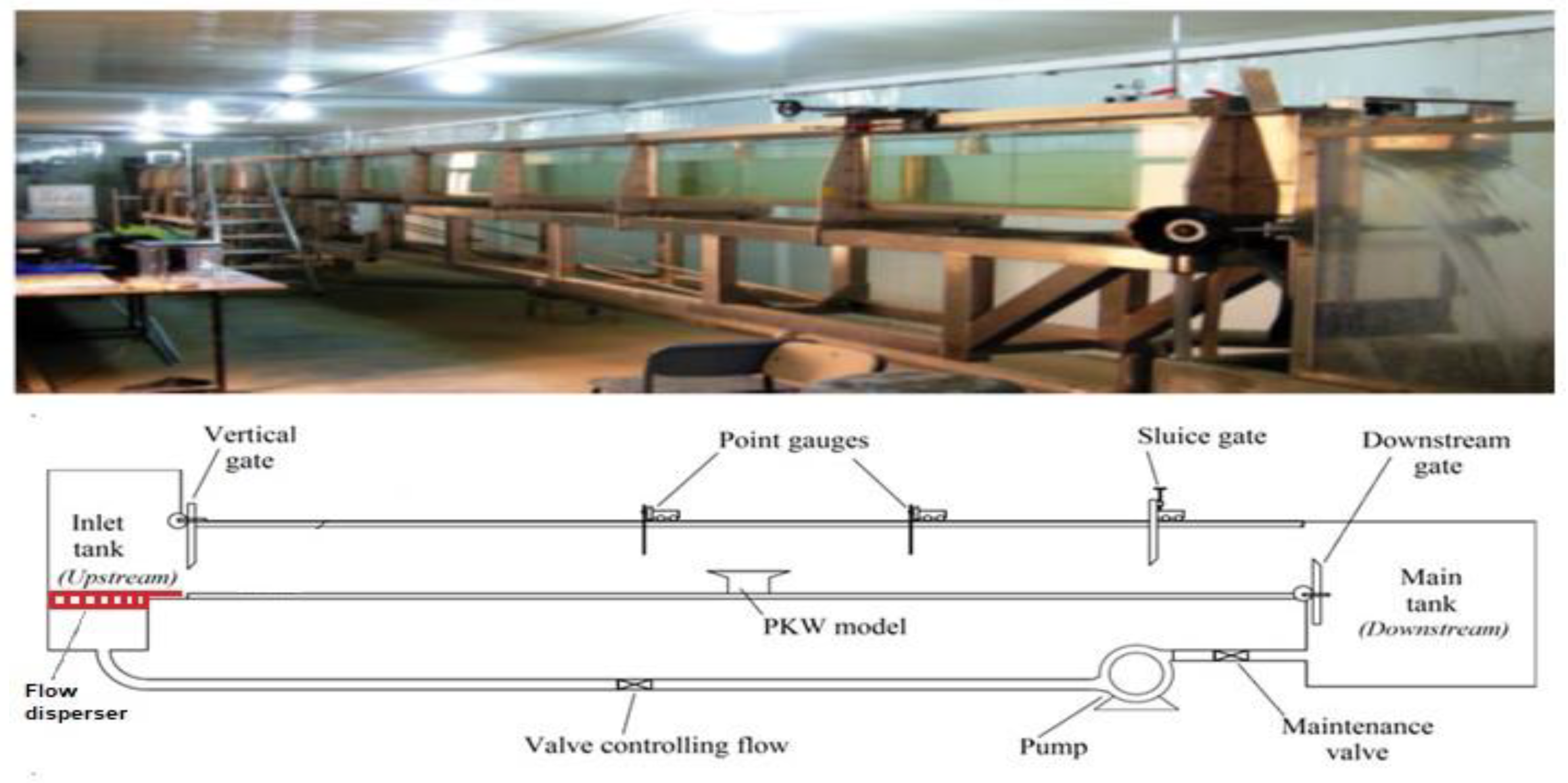
Tests were conducted in the glass flume at Kufa University’s Department of College Engineering for Water Resources and Hydraulic Structures. The flume measured 15 m long, 0.3 m wide and 0.45 m high. Reservoirs at the flume’s start and end regulate intake and output. The flume’s glass sides facilitate the observation of hydraulic phenomena and the water level profile. Figure 3 illustrates the fundamental structure of the flume.
The flow was facilitated by a pump originating from the primary reservoir. Gate valves regulated the flow (throttle valve) in a closed-loop water system. Flume discharge is measured using a calibrated rectangular weir and ultrasonic flowmeters. After entering the flume from the input tank via the flow disperser tool, the flow entered the flume over the RPKW model. After going through the rectangular weir, the return conduit system released the water into the main reservoir. Discharge varied between 5 and 23 L/s. Table 2 lists the geometric elements of the RPKW, as shown in Figure 2.
A 3D printing method is a new innovative option for hydraulic experimental modelling that may provide a more adequate and quick model creation, particularly for models that have complicated geometries. The present study used 3D printing technology to fabricate hydraulic scaled models intended for experimental purposes within a laboratory setting. Various types of weir models were fabricated. This study analysed the effects of the parapet wall’s linearity on PKW performance. Three alternative parapet wall configurations with a total of 27 RPKW type-A models were included in the current study. Table 3 presents a testing matrix that includes all weirs that require testing. The experiments used three different parapet wall profiles with flat crests: rectangular, triangular and trapezoidal. The parapet wall’s profile form was analysed with respect to three distinct heights, i.e., R1 = 1.5 cm, R2 = 3 cm and R3 = 4.5 cm (R/P = 0.12, 0.24 and 0.36). As shown in Figure 4, the placement of parapet walls on a weir crest can be achieved through three modes, covering the (a) full crest (M1), (b) sides and inlet keys and (c) sidewalls only.

2.3. Experimental Process

On the weir’s crest, parapet walls were first constructed with the specified height, installation pattern and profile form. By using a pump, an equipped rectangular weir and ultrasonic flowmeter equipment, the flow was redirected through the flume to maintain a constant outflow. As the flow stabilised, measurements of the water level at the piezometric head and upstream were made using a metallic point gauge at 32 cm from the weir’s crest (ho) and at the crest (h1). The continuity equation was used to calculate the upstream flow velocity. Equation (4) may be used to obtain the upstream total head.
Ho = ho + V2/2g,
where Ho (m) represents the total head upstream, with respect to the weir peak height; ho (m) is the upstream piezometric head; and Vo (m/s) is the upstream flow velocity.

3. Results and Discussion

The piano key weir can be used in irrigation canals or dams. Given the huge discharge capability of these weirs, water levels in the waterways may drop remarkably during low water seasons, preventing upstream flow diversion. From time to time, the weir height must be raised to store more water in the ponds. The parapet walls have been observed to cause effects, such as increase in the crest and upstream water levels. The upstream water level, the interference flow from the side walls and the discharge coefficient of RPKWs were all analysed in this part to determine how the parapet walls affect these variables and ultimately increase the discharge capacity.

3.1. Effect of Parapet Walls on Discharge Coefficient and Performance Efficiency

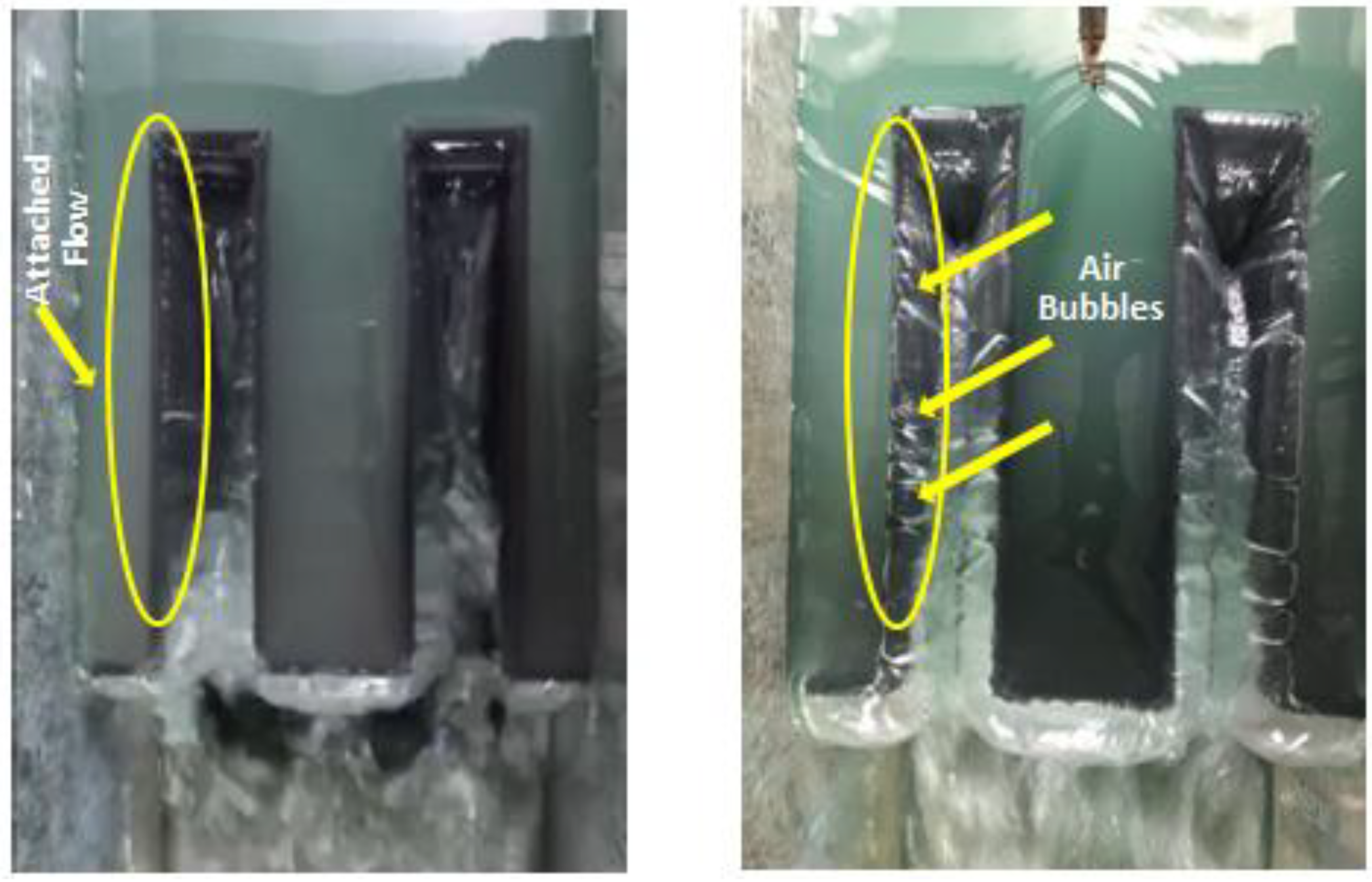
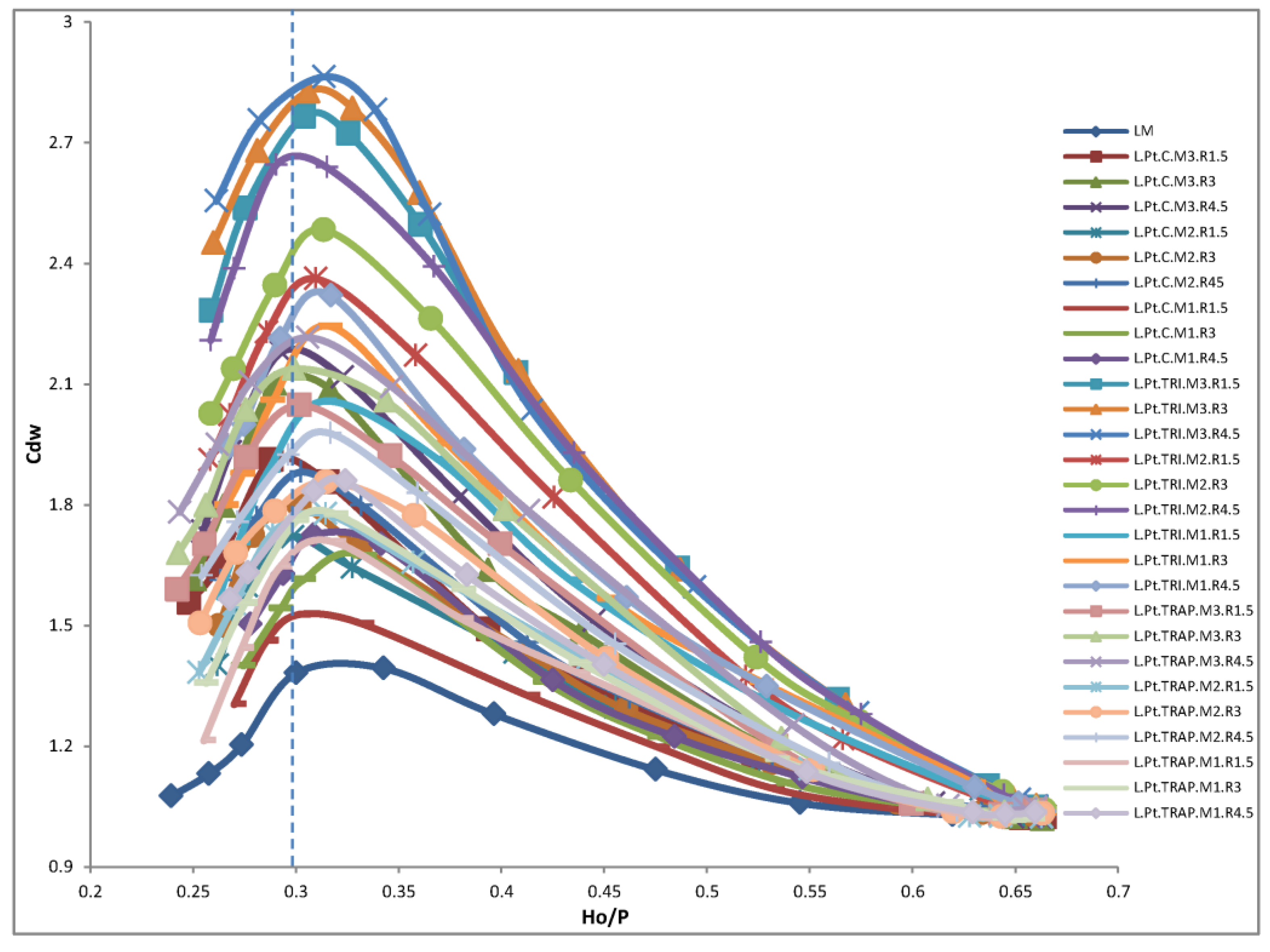
PKW discharge coefficient variations are explained and analysed in this part. Figure 7 shows that Cdw is an increasing function of Ho/P under low head situations (Ho/P < 0.3), which correlate to the clinging phase in Figure 5. In this phase, an increase in Ho/P leads to a heightening of subatmospheric pressures below the nappe, which in turn raises Cdw. However, once the aerated system begins, the Cdw tendency no longer increases. The linearity of the parapet walls (profile shapes-triangular and trapezoidal) was used to address the issue of the slope’s monotonic decline with Ho/P, which may be due to local submergence expansion in the outlet keys (Figure 6) and water flow contraction in the inlet keys, both of which reduce the effective crest length and thus the sidewall performance.
In general, the weirs can be described by Equation (5):
Q = 2 3 Cdw 2 g L H o 3 / 2 ,
where Table 1 defines these parameters. Given that the parapet walls in M2 and M3 only cover part of the weir crest, different weir areas have varying total heads. Equation (6) was used to calculate the discharge coefficient in the parapet wall setup instance by adding the potential discharges from the inlet and outlet keys and sides [25]:
Qtr = Qwi + Qwo +Qws,
where Qtr, Qwi, Qwo and Qws represent the potential discharge along the sidewall length, key width and crest length, respectively. Equations (7)–(9) were used to compute the theoretical discharges for the M1, M2 and M3 instalment modes in accordance with the variations in total head at the weir’s various points for various configurations [25]:
Qtr = 2 3 Cdw 2 g L ( H o R ) 3 / 2 ,
Qtr = 2 3 Cdw 2 g [ 2 nB + nWi Ho R 3 / 2 + ( nWo ) Ho 3 / 2 ,
Qtr = 2 3 Cdw 2 g [ 2 nB Ho R 3 / 2 + n ( Wi + Wo ) Ho 3 / 2 .
In this equation, n, B, Wi, Wo, Ho and R represent the number of cycles, the length of the sides, the width of the entry and exit keys, the total head upstream and the parapet height, respectively.
Lastly, on the basis of actual discharge, Equation (10) was used to obtain Cdw:
Cdw = Q a Q t r ,
where Qa denotes the actual discharge (i.e., experimental discharge), Cdw is the discharge coefficient when parapet walls are present, and Qtr is the total theoretical discharge.
To perform subsequent analysis of parameters for evaluating the performance of the physical model based on the efficiency of the piano key weir’s discharge capacity, 27 PKW models were manufactured with parapet walls considering their linear geometric characteristics (side view shapes). Figure 7 shows that the PKW’s Cdw depends on the Ho/P ratio of the water head. It shows the parapet walls’ impact. The discharge coefficient was greatly enhanced by the addition of parapet walls, resulting in a marked increase in the PKW’s discharge capacity. Discharge coefficients vary depending on the profile shape and height of the parapet walls in the PKW models.
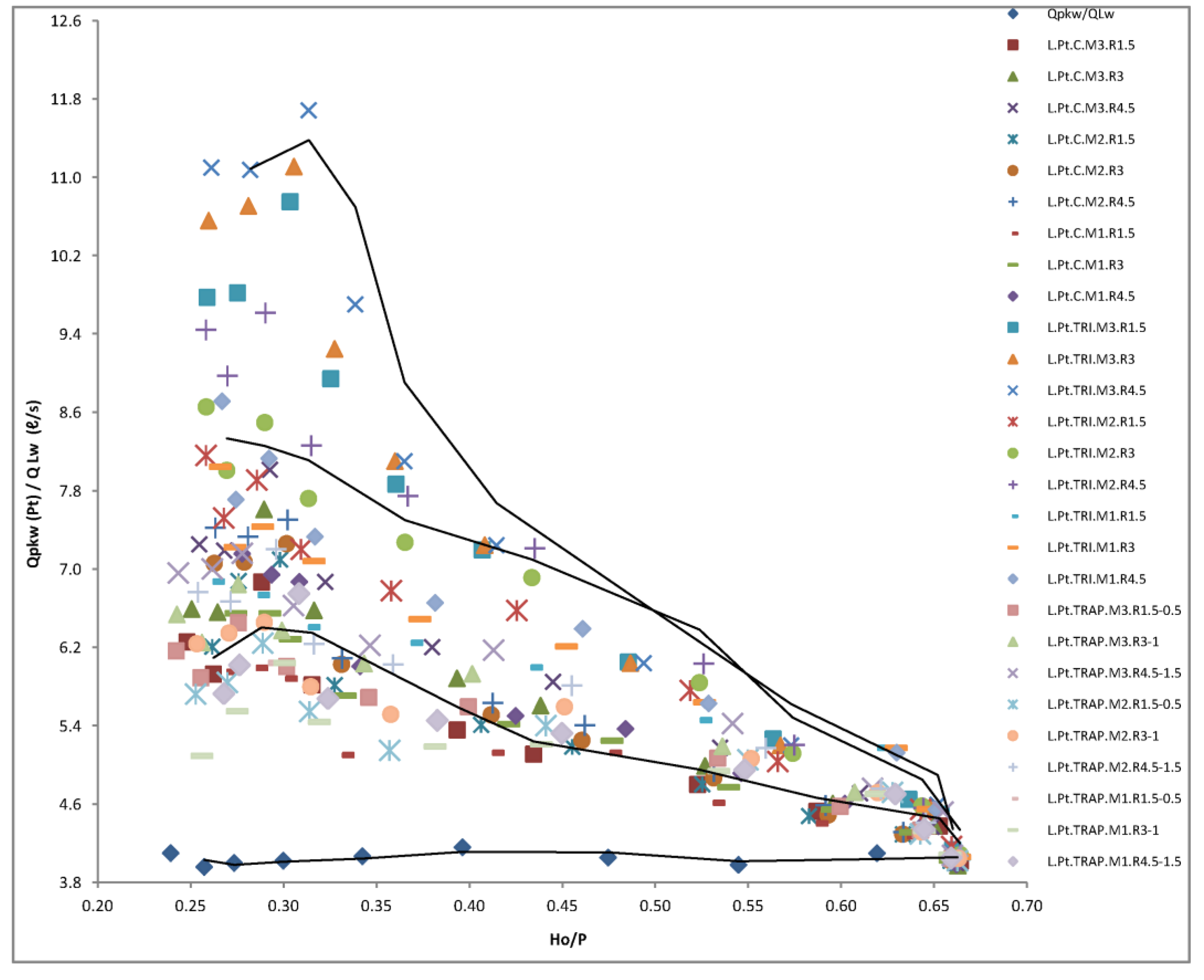
The discharge rates of models and their comparisons are presented in Figure 8 in a manner similar to the analysis of the parapet wall’s profile forms. The model’s discharge for triangular profile shape is greater than that of the trapezoidal and rectangular models (about 20%), whereas the discharge of the trapezoidal model is slightly greater than that of the rectangular one. The RPKW models’ proportional discharge of different heights and maximum flow occurs at low water heads for various profile shapes (Ho/P = 0.30). All the models’ relative discharge was highest at a water head Ho/P of approximately 0.65, which is within Ho/P > 0.30. When the water level rose, all models followed a similar variation rule for the proportional discharge. All models had a discharge that was between 14% and 20% greater than weirs without parapet walls under the same water-head circumstances. In all the water-head situations, the model with triangle profile shapes generally showed the highest discharge efficiency.
As shown in Figure 9, the relative RPKW performance coefficients of different linearity profile shapes of parapet walls (triangular and trapezoidal) were 2.9 and 1.8 at Ho/P = 0.30 and 0.65, respectively, with a decreasing mean value of 2.2, as compared with those of the constant linearity profile shape of the parapet wall (rectangular). In addition, the triangular model (with M3 mode and R3 of 4.5 cm) performed better than the other RPKW versions.
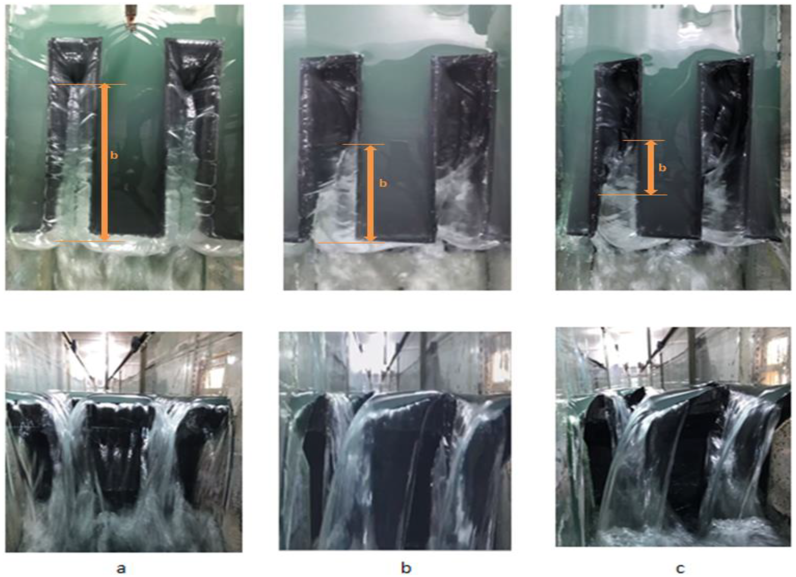
As a result, a parapet wall with a higher and steeper gradient (a triangle profile form) produced a better discharge efficiency. With a parapet wall and utilising its linearity of profile shape for a PKW with a set weir height, this is analogous to raising the overall weir height gradually to a point where the discharge capacity is maximised, which was consistent with the findings of Machiels and colleagues [14]. In consideration of the parapet walls’ primary effect and its linearity for profile forms, a parapet wall above the inlet crest raises the water level in the inlet key, thus reducing longitudinal velocity and optimising the discharge efficiency of the lateral and outlet crests. The flow patterns of three profile shapes of PKW parapet walls at low and high flow rates are shown in Figure 10 and Figure 11. Given the limited discharge rate, the flow of water is observed equitably spread over each overflow crest in the case of PKW’s rectangular profile form. By contrast, nappes that are thoroughly ventilated are generated downstream from the outlet key for the model’s triangular and trapezoidal profile forms. In the downstream region of the inlet, partially aerated linked nappes that exhibit oscillatory behaviour over time are generated. With this type of flow, the outflow is slightly increased due to the negative pressure beneath the water’s nappes; however, it also runs the risk of causing vibration and structural damage to the structure [26]. Nevertheless, addressing this situation with a deviation in the direction and intensity of flow nappes due to the linearity of the profile disperses and reduces the occurrence of vibration. Compared with the trapezoidal model, which has a small cavity, the triangular form has the biggest empty internal area. Most rectangular profiles formed downstream of the entry key are filled when the flow rate is high because the vertical parapet wall (particularly in rectangular cases) and its linearity (in trapezoidal and triangular cases) direct the upward jet and sideward; by contrast, the inlet crest’s vertical flow velocity component rises, resulting in a wider water jet from the inlet key for the same flow compared with that without the parapet walls.

3.2. Parapet Walls Affect the Water Level and Upstream Head

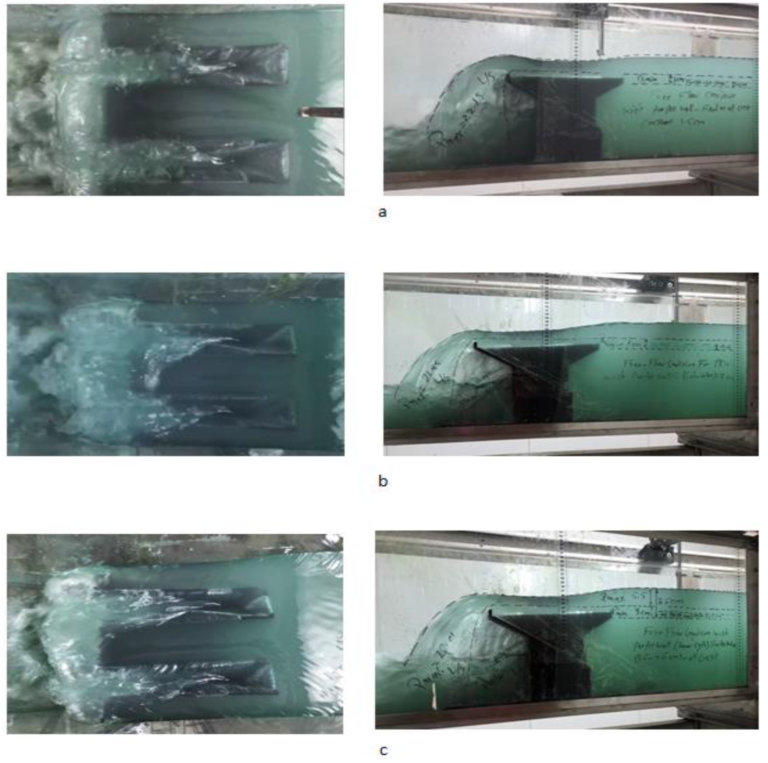
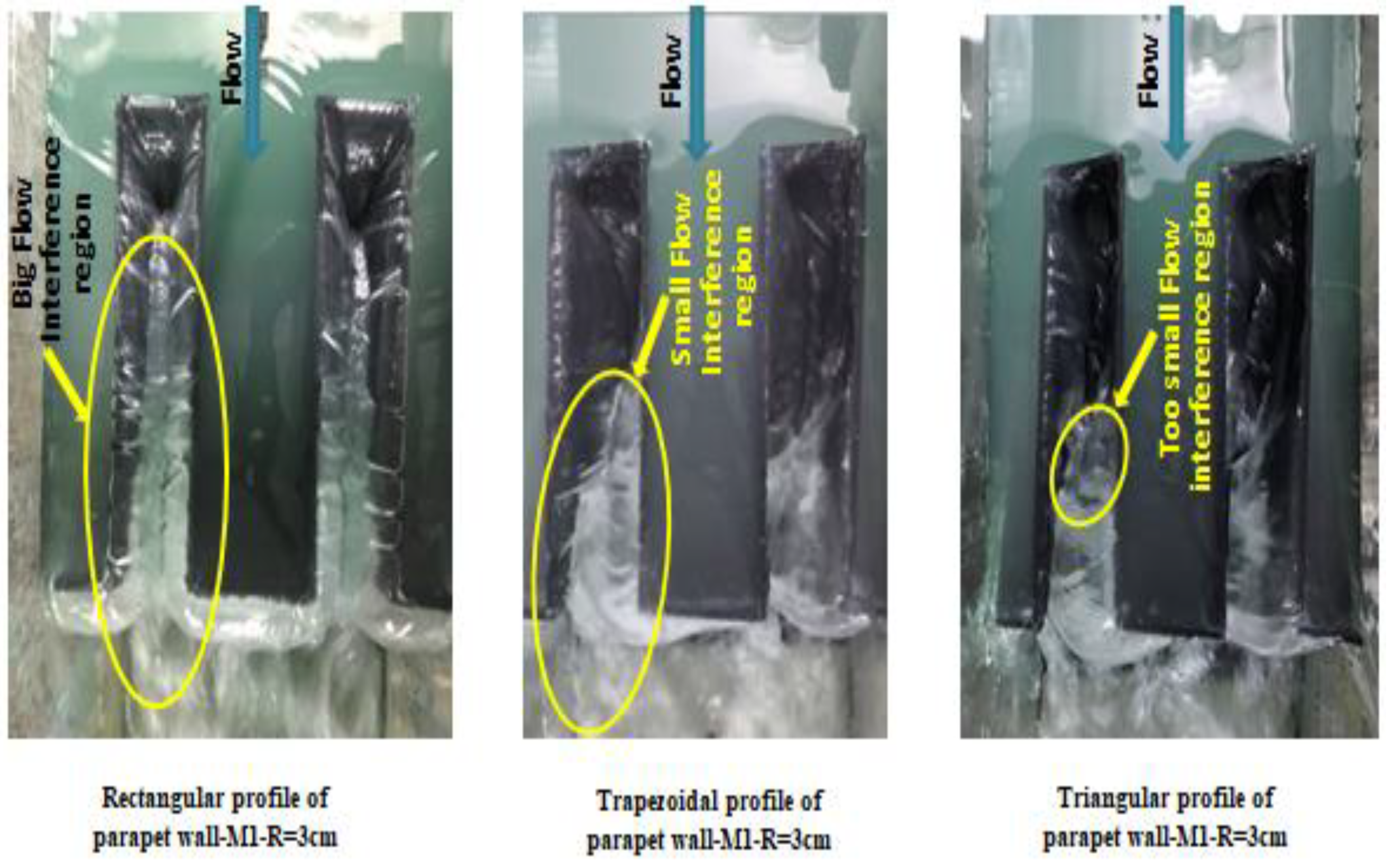
Figure 12 shows the flow through the RPKW for parapet walls with rectangular, triangular, and trapezoidal profile forms and M1 design. The sidewalls’ openings in the RPKW case did not prevent interferences with the flow of outlet keys from being seen in large discharges even if they were extremely small. Furthermore, using the linearity of the profile shape of the parapet wall (triangular and trapezoidal) leads to a reduction in the flow interference between the side walls, thus increasing the PKW’s discharge capacity. An academic study claimed that adding a parapet wall to a PKW’s inlet key increases flow capacity. However, no remarkable improvement was observed when the same was added to the outlet key [27].
However, when parapet walls were fixed on the weir crest using a trapezoidal and triangular profile, the overlapping area of the lateral flow was smaller in the trapezoidal profile case than in the case of the rectangular profile. It almost diminishes in the case of the triangular profile, in addition to the small area of overlapping when compared with the trapezoidal and especially the rectangular profile.
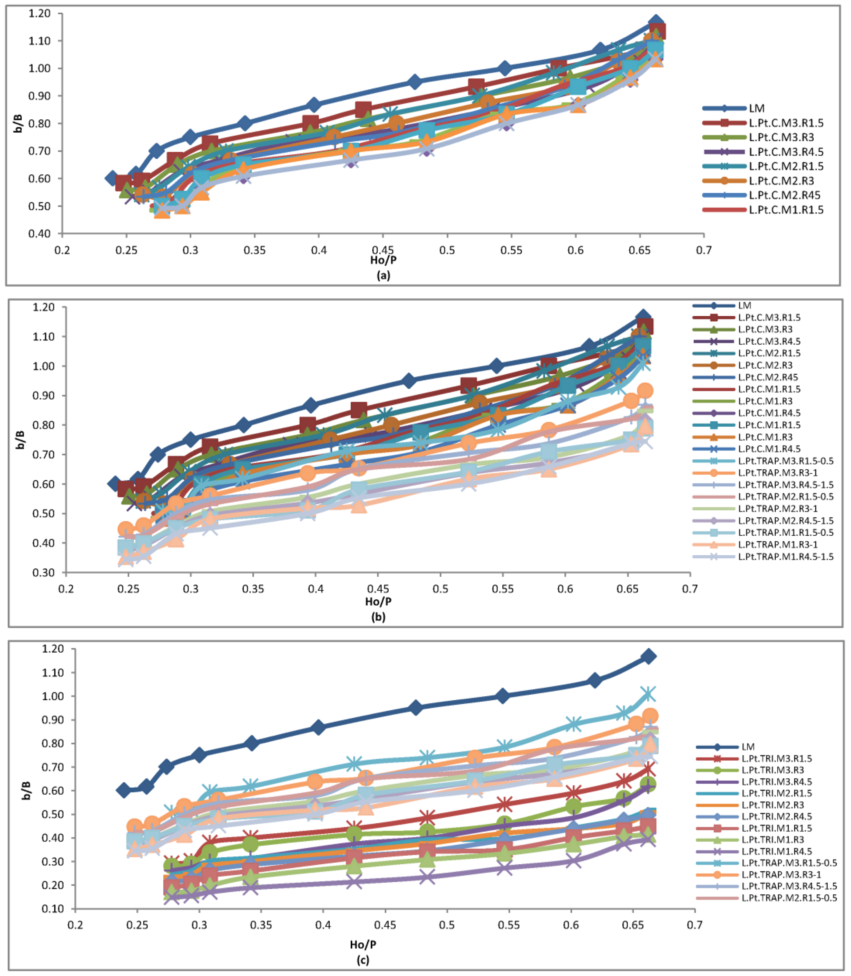
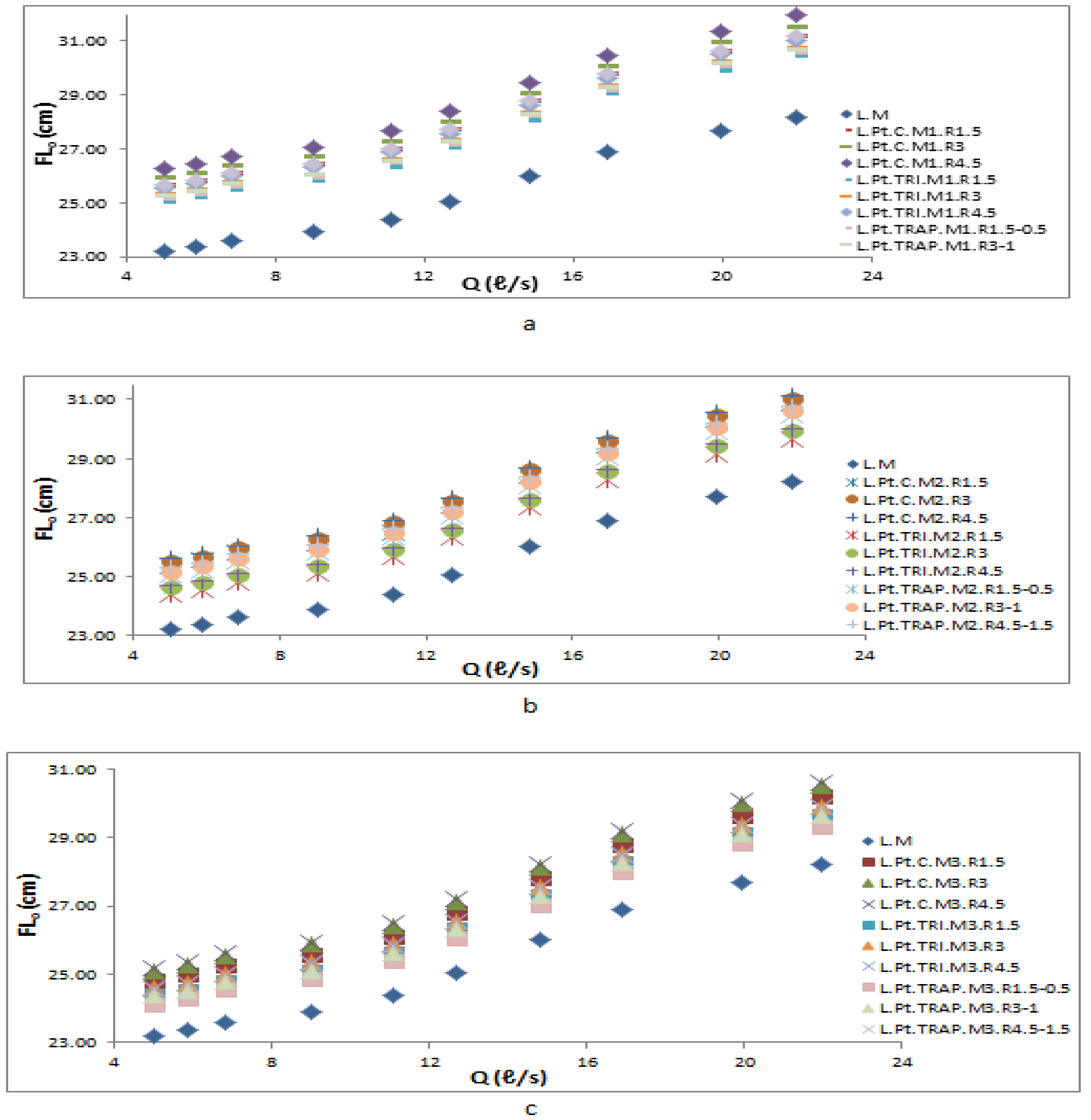
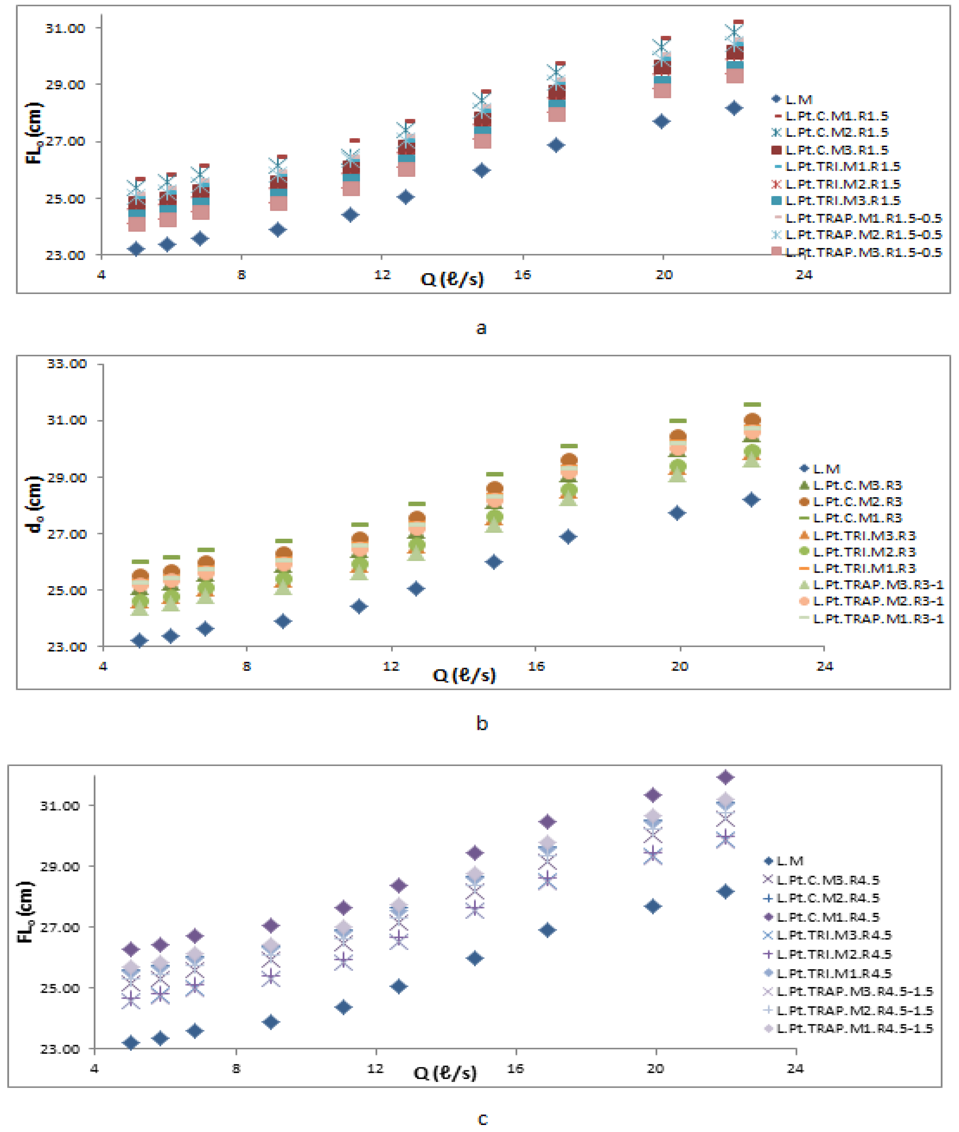
Figure 13 and Figure 14 show the water levels of the PKW’s upstream in relation to the flume’s base (FL0) for different discharges in the absence of a parapet, with three instalment modes of parapet walls (M1, M2 and M3) for three R/P ratios (0.12, 0.24, and 0.36). In all construction versions, the parapet walls and linearity raised the water level upstream of the weir. Table 4 shows the average percentage rises in water level and total upstream flow in the setup compared with that without parapet walls.

3.3. Effects of Parapet Walls Height and Profile Shape (The Linearity)

According to Table 4 and Figure 13, an increase in the height of the parapet wall results in an increase in the water level and overall upstream head. Taking the M1 configuration with parapet walls as an example, for three types of parapet wall profiles (rectangular, triangular, and trapezoidal) and for three R/P values of 0.12, 0.24, and 0.36, the water level rose on average by 10%, 14.3%, and 21%; for the rectangle profile form of the parapet wall, the water level rose by 44%, 63%, and 91%, respectively of the total upstream head. But, the water level rose by an average of 4.5%, 7.7%, and 11% with respect to the parapet wall’s triangular form corresponding to 20%, 34%, and 48% of the total upstream head. Compared with the trapezoidal profile form of the parapet wall there were 5.75%, 9.8%, and 14.1% on average rises in the water level, and 25%, 49%, and 62%, respectively in the total upstream head. Each of the three parapet wall profile forms was contrasted with an instance without a parapet. The percentage rises in the total upstream head for the rectangular profile form in the M1 mode were 1.4 and 2.1 times.
As the parapet height doubled or tripled, the triangular profile shape resulted in percentage increases of 1.7 and 2.4 times for the total upstream head. The trapezoidal profile form was linked with specific values, and the total upstream head increased by 1.9 and 2.5 times. The observed augmentation for the M2 modality was 1.8 and 2.6 times. The rectangular profile experienced an increase, as appropriate for its respective characteristics. The values for M3 were found to be 1.75 and 2.5 times for the rectangular profile. Similarly, an increase was observed for other profiles, with the values for M2 being 1.8 and 2.6 times for the triangular profile and for M3 being 1.7 and 2.5 times. For the trapezoidal profile, the values for M2 were 1.7 and 2.4 times; for M3, they were 1.7 and 2.5 times. Thus, a direct correlation exists between the height of the parapet and the water level and total upstream head across all modes.

3.4. Effect of the Instalment Mode and Profile Shape, Specifically the Linearity, on the Parapet Walls

As shown in Table 4 and Figure 14, for M1, M2 and M3 modes, parapet walls with a low height (R/P = 0.12) increased the total upstream head by 44%, 29% and 24%, respectively. The biggest and lowest growth percentages in terms of the total head correspond to the M1 (63%) and M3 (42%) modes, respectively, doubling the height (R/P = 0.24). The installation modes’ connection is the same for the triangular and trapezoidal profile shapes and has an R/P ratio of 0.36. The mode exchanges of M1 to M2 and M1 to M3 reduce the rising percentage of the total head by 15% and 20%, respectively, when the parapet wall is built with R/P = 0.12 (triangular and trapezoidal). When R/P = 0.24, the decreases for M1 to M2 and M1 to M3 were 11% and 21%, respectively, whereas the decreases for other profile shapes were 7% and 12% for triangular and 6% and 16% for trapezoidal. When R/P = 0.36, the rising percentage decreased by 16% and 31% for the triangular profile and 10% and 22% for the trapezoidal profile. The M1 mode of the low-height (R/P = 0.12) parapet wall slightly improved the upstream head. When the installed parapets on the inlet and outlet keys were removed or the mode was switched from M2 to M3, the inlet and outlet keys continued to play the same part in the flow’s circulation and discharge as before. Removing the parapet wall and switching out M1 for M2 and M1 for M3 had minimal effects on the inlet and outlet keys’ performance in flow discharge. By contrast, the removal of the parapet walls installed on the inlet and outlet keys and the mode exchange to M2 and M3 increased the role of the key’s inflow discharge and further reduced the water level when the parapet walls were established with high elevation (R/P = 0.36) and M1 mode and due to the noticeably increased total head (91%). Data showed that increasing the height of the parapet walls at the top of the RPKW increases the effect of setup modes on water level fluctuations. Moreover, the effect of the side shape of the parapet wall, specifically in the case of the side shape being rectangular, the increase in the water level is greater than if it was a triangle or a trapezoid. By contrast, the discharge capacity is greater in the case of a triangle and less in the case of a rectangle due to the reduction of interference that occurs from the side run-off in the case of the triangle and in the case of the trapezoid. Consequently, the linearity of the barricade affects the drainage capacity and thus the performance efficiency of the dam. In addition, the overlapping area of the lateral flow begins to decrease in the case of the trapezoid and is almost nonexistent in the case of the triangle in comparison with the rectangular profile.

3.5. Effect of the Profile Form of a Parapet Wall

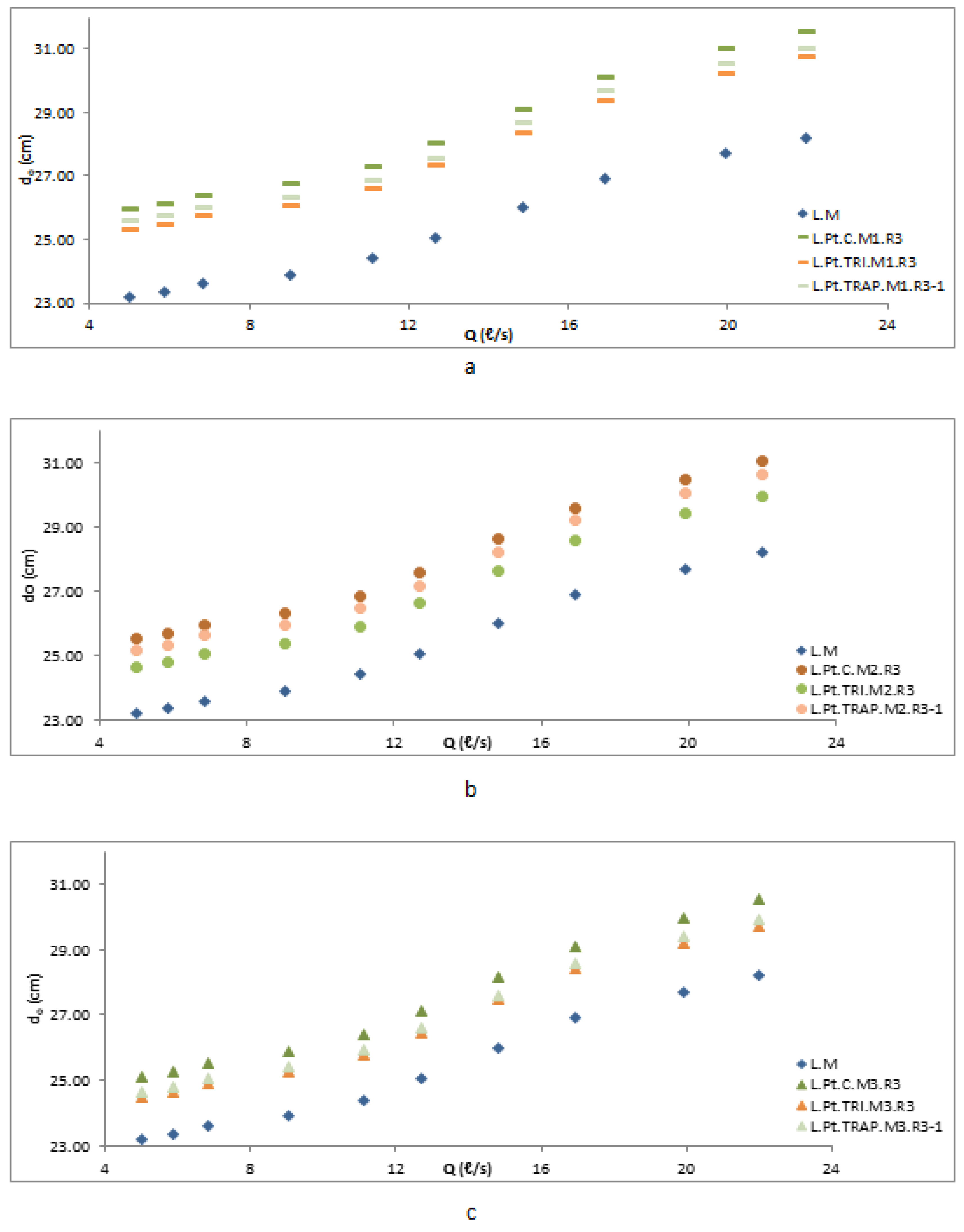
Figure 15 shows how the parapet wall shape with R/P = 0.24 affects water level changes upstream of the weir in modes M1, M2 and M3. The water level in the TRI (linearity covariance) case would be lower than in the TRAP (linearity covariance) and rectangular (constant linearity) situations during large discharges and when it pertains to modes M1 and M3. Conversely, within the M2 installation mode, water level fluctuations have been mitigated for diverse profile configurations. Table 5 shows the percentage rise in the total head for parapet walls made in various modes and profile forms compared with those without parapet cases. Figure 15 and Table 5 show that profile form has the greatest and least effect on water variations and total head under the M1 and M3 modes, respectively. Moreover, erecting parapet walls with a triangle profile results in lower rises in total head and water level than doing so with a rectangular or trapezoidal shape. M3 removes the parapet walls above the inlet and outlet keys, whereas M2 and M1 leave them on the outlet key and all over the weir crest, respectively. Thus, parapet walls placed on the widths of the inlet and outlet keys, perpendicular to the flow direction, have a greater effect on variations in water level and overall head than do parapet walls installed on the sides.

4. Conclusions

According to reports on dam collapses, weir discharges with inadequate capacities lead to one-third of the collapses. PKW is a standard nonlinear weir used for increasing discharge capacity. Performance suffers in the RPKW type because the sidewalls are parallel, which interferes with the flow passing over them. Parapet walls, key apertures, and linearity (profile shapes) of parapet walls reduce flow interference and enhance weir efficiency. This study examined how parapet wall height, installation mode, and profile form affect RPKW water level and discharge coefficient. The RPKW’s sidewall length was B = 30.3 cm, and its height was P = 12.6 cm. Three parapet wall heights, i.e., 1.5, 3 and 4.5 cm, were selected. Three parapet wall profiles, i.e., rectangle, triangle and trapezoid, were also chosen. Additionally, the crest’s parapet walls were built using M1, M2 and M3 forms. This study’s most remarkable results are as follows:
  • At an R/P ratio of 0.36, the transfer of mode from M1 to M3 results in a reduction of parapet wall effect on the rising total head by 32%, 28% and 33% for parapet walls with rectangular, triangular and trapezoidal profile shapes, respectively.
  • When comparing the constant linearity (rectangular) profile of parapet walls with R/P = 0.36 to RPKW without parapet walls, the discharge coefficient of the weir in the M3 mode exhibited a 26–15% increase compared with the M1 and M2 situations, respectively. In the context of parapet wall variation linearity, specifically triangular and trapezoidal profiles with an R/P ratio of 0.36, the discharge coefficient of the weir in M3 mode exhibits a notable increase of 23–10% and 20–13% compared with M1 and M2 modes, respectively.
  • In situations where parapet walls possess a constant linearity (rectangular) profile with R/P = 0.36, a comparison with an RPKW lacking parapet walls reveals that the weir’s discharge capacity in M3 mode is 15.6% greater than that of M1 and M2 positions. The variance of linearity between triangular and trapezoidal profile shapes is 20% and 15.6%, respectively.
  • The geometric configuration of the parapet walls situated along the width of the inlet and outlet keys exerts a considerable influence on alterations in water level and discharge coefficient.
  • The linearity of parapet walls is effective in the improvement of the RPKW function.
  • When variations in the performance, upstream water level, and discharge coefficient (Cdw) of RPKWs are to be studied, the effects of the free flow condition must be considered.
  • The novel parapet wall designs investigated in this study, along with their demonstrated impact on water level variations and discharge capacity, can contribute to enhancing the efficiency of Piano Key Weirs (PKWs). By implementing these advanced configurations, we can achieve significant improvements in water control and discharge capacity, which are critical aspects for effective water management and maximizing storage capacity.
  • The value of Ho/P = 0.30 can be the typical threshold for the aerated state of the analysed PKWs. However, the aeration states may vary based on the specific weir geometry (sensitive to weir scale and profile shape of parapet wall). The present investigation, along with previous research [28], indicates that a PKW exhibits superior aeration characteristics when compared with a labyrinth weir.
  • The utilisation of 3D printing technology, specifically for models with intricate geometries, may provide a more suitable and expeditious approach to creating models for hydraulic experimental modelling.
  • The optimized parapet wall configurations identified in our study can contribute to the design and operation of weirs and dams by improving their discharge capacity and overall performance efficiency.
  • By reducing flow interference and enhancing weir efficiency, these findings can help mitigate the risk of collapses resulting from inadequate discharge capacities.

Author Contributions

M.S., methodology, investigation, formal analysis, writing original draft; B.Y., formal analysis, writing review and editing, supervision; S.K., methodology, resources, review and editing, supervision; B.M., methodology, review and editing; N.A.A., methodology, review and editing. All authors have read and agreed to the published version of the manuscript.

Funding

This research received no external funding.

Data Availability Statement

Not applicable.

Conflicts of Interest

The authors declare no conflict of interest.

References

  1. Lantz, W.; Crookston, B.M.; Palermo, M. Apron and cutoff wall scour protection for piano key weirs. Water 2021, 13, 2332. [Google Scholar] [CrossRef]
  2. Anderson, R.M.; Tullis, B.P. Piano Key Weir Hydraulics and Labyrinth Weir Comparison. J. Irrig. Drain. Eng. 2013, 139, 246–253. [Google Scholar] [CrossRef]
  3. Bekheet, A.A.; AboulAtta, N.M.; Saad, N.Y.; El-Molla, D.A. Effect of the shape and type of piano key weirs on the flow efficiency. Ain Shams Eng. J. 2022, 13, 101620. [Google Scholar] [CrossRef]
  4. Safarzadeh, A.; Noroozi, B. 3D Hydrodynamics of Trapezoidal Piano Key Spillways. Int. J. Civ. Eng. 2017, 15, 89–101. [Google Scholar] [CrossRef]
  5. Bhukya, R.K.; Pandey, M.; Valyrakis, M.; Michalis, P. Discharge Estimation over Piano Key Weirs: A Review of Recent Developments. Water 2022, 14, 3029. [Google Scholar] [CrossRef]
  6. Oertel, M.; Shen, X. 3D Printing Technique for Experimental Modeling of Hydraulic Structures: Exemplary Scaled Weir Models. Water 2022, 14, 2153. [Google Scholar] [CrossRef]
  7. Belzner, F.; Merkel, J.; Gebhardt, M.; Thorenz, C. Piano Key and Labyrinth Weirs at German waterways: Recent and future research of the BAW. In Labyrinth Piano Key Weirs III—PKW 2017; CRC Press: Boca Raton, FL, USA, 2017; pp. 167–174. [Google Scholar]
  8. Ouamane, A.; Lempérière, F. Design of a new economic shape of weir. In International Symposium on Dams in the Societies of the 21st Century; CRC Press: Boca Raton, FL, USA, 2006; Volume 1, pp. 463–470. [Google Scholar]
  9. Machiels, O. Experimental study of the hydraulic behaviour of Piano Key Weirs. Ph.D. Thesis, University of Liege, Liège, Belgium, 2012. [Google Scholar]
  10. Anderson, R.; Tullis, B. Influence of Piano KeyWeir geometry on discharge. In Labyrinth and Piano Key Weirs; CRC Press: Boca Raton, FL, USA, 2011; pp. 75–80. [Google Scholar]
  11. Anderson, R.M.; Tullis, B.P. Comparison of Piano Key and Rectangular Labyrinth Weir Hydraulics. J. Hydraul. Eng. 2012, 138, 358–361. [Google Scholar] [CrossRef]
  12. Kabiri-Samani, A.; Javaheri, A. Discharge coefficients for free and submerged flow over Piano Key weirs. J. Hydraul. Res. 2012, 50, 114–120. [Google Scholar] [CrossRef]
  13. Leite Ribeiro, M.; Bieri, M.; Boillat, J.-L. Hydraulic capacity improvement of existing spillways—Design of a piano key weirs. In Proceedings of the Proceedings (on CD) of the 23rd Congress of the Int. Commission on Large Dams CIGB-ICOLD, Brasilia, Brazil, 25–29 May 2009; pp. 100–118. [Google Scholar]
  14. Machiels, O.; Erpicum, S.; Archambeau, P.; Dewals, B.; Pirotton, M. Parapet Wall Effect on Piano Key Weir Efficiency. J. Irrig. Drain. Eng. 2013, 139, 506–511. [Google Scholar] [CrossRef]
  15. Erpicum, S.; Archambeau, P.; Dewals, B.; Pirotton, M. Overview of design and construction of 11 Piano Key Weirs spillways developed in France by EDF from 2003 to 2016. In Labyrinth and Piano Key Weirs III; CRC Press: Boca Raton, FL, USA, 2017; pp. 27–36. [Google Scholar]
  16. Hu, H.; Qian, Z.; Yang, W.; Hou, D.; Du, L. Numerical study of characteristics and discharge capacity of piano key weirs. Flow Meas. Instrum. 2018, 62, 27–32. [Google Scholar] [CrossRef]
  17. Bilhan, O.; Aydin, M.C.; Emiroglu, M.E.; Miller, C.J. Experimental and CFD Analysis of Circular Labyrinth Weirs. J. Irrig. Drain. Eng. 2018, 144, 04018007. [Google Scholar] [CrossRef]
  18. Leite Ribeiro, M.; Bieri, M.; Boillat, J.L.; Schleiss, A.J.; Singhal, G.; Sharma, N. Discharge Capacity of Piano Key Weirs. J. Hydraul. Eng. 2012, 138, 199–203. [Google Scholar] [CrossRef]
  19. Haghnazar, H.; Saneie, M. Impacts of pit distance and location on river sand mining management. Model. Earth Syst. Environ. 2019, 5, 1463–1472. [Google Scholar] [CrossRef]
  20. Ettema, R.; Arndt, R.; Roberts, P.; Wahl, T. Hydraulic Modeling; Amer Society of Civil Engineers: Reston, VA, USA, 2013; ISBN 0-7844-0415-1. [Google Scholar]
  21. Monjezi, R.; Heidarnejad, M.; Masjedi, A.; Purmohammadi, M.H.; Kamanbedast, A. Laboratory investigation of the Discharge Coefficient of flow in arced labyrinth weirs with triangular plans. Flow Meas. Instrum. 2018, 64, 64–70. [Google Scholar] [CrossRef]
  22. Pfister, M.; Capobianco, D.; Tullis, B.; Schleiss, A.J. Debris-Blocking Sensitivity of Piano Key Weirs under Reservoir-Type Approach Flow. J. Hydraul. Eng. 2013, 139, 1134–1141. [Google Scholar] [CrossRef] [Green Version]
  23. Erpicum, S.; Tullis, B.P.; Lodomez, M.; Archambeau, P.; Dewals, B.J.; Pirotton, M. Scale effects in physical piano key weirs models. J. Hydraul. Res. 2016, 54, 692–698. [Google Scholar] [CrossRef] [Green Version]
  24. Novak, P.; Moffat, A.I.B.; Nalluri, C.; Narayanan, R.A. Hydraulic Structures, 4th ed.; CRC Press: Boca Raton, FL, USA, 2007. [Google Scholar]
  25. Kheir-Abadi, M.A.; Moghadam, M.K.; Sabzevari, T.; Ghadampour, Z. An experimental study of the effects of the parapet walls geometry on the discharge coefficient of trapezoidal piano key weirs. Flow Meas. Instrum. 2020, 73, 101742. [Google Scholar] [CrossRef]
  26. Denys, F.J.M.; Basson, G.R. Unsteady Hydrodynamic Behavior at Piano Key Weirs. J. Hydraul. Eng. 2020, 146, 04020028. [Google Scholar] [CrossRef]
  27. Laiadi, A.; Athmani, B.; Belaabed, F.; Ouamane, A. The effect of the geometric shape of the alveoli on the performance of Piano Key Weirs. In Labyrinth and Piano Key Weirs III—PKW 2017; CRC Press: Boca Raton, FL, USA, 2017; pp. 93–100. [Google Scholar]
  28. Crookston, B.M.; Tullis, B.P. Hydraulic Design and Analysis of Labyrinth Weirs. I: Discharge Relationships. J. Irrig. Drain. Eng. 2013, 139, 363–370. [Google Scholar] [CrossRef]
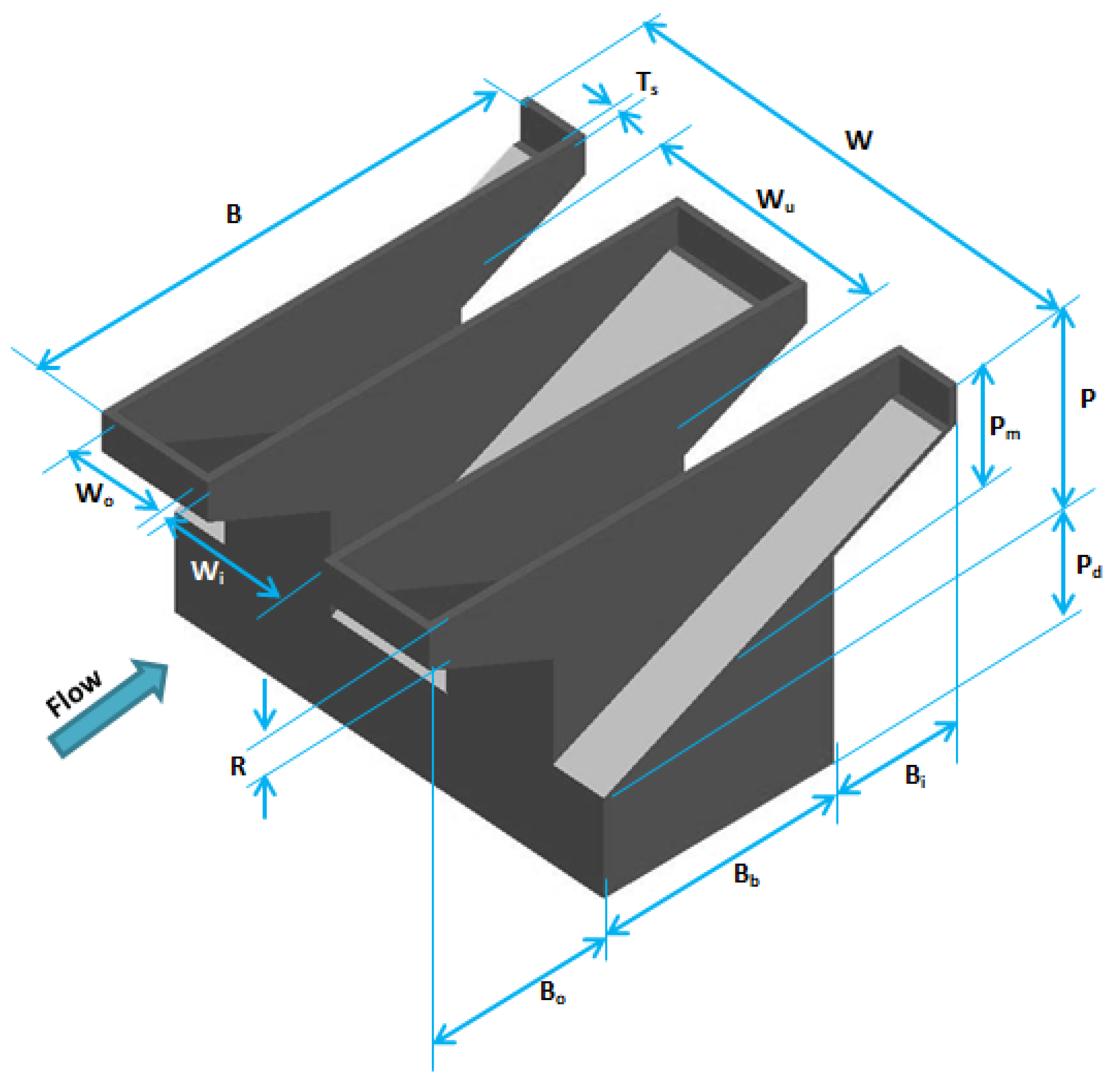
Figure 1. Geometric parameters of a 3D piano key weir (PKW).
Water 15 02307 g001
Figure 2. Parameters in the geometry of RPKWs: (a) 3D view (b) top view (c) section A-A.
Water 15 02307 g002
Figure 3. Schematic of the PKW and laboratory equipment.
Water 15 02307 g003
Figure 4. Three main techniques for installing parapet walls on top of the RPKW: (a) M1, (b) M2 and (c) M3.
Water 15 02307 g004
Figure 5. Transition from clinging to leaping to a springing nappe on the side crest.
Water 15 02307 g005
Figure 6. Variations of interference length of RPKW between (a) with/without parapet wall (rectangular profile shape) (constant linearity), (b) constant linearity (rectangular)/variation linearity (trapezoidal) profile shape, (c) trapezoidal/triangular profile shape.
Water 15 02307 g006
Figure 7. Parapet wall height and profile shape influence the RPKW model’s Cdw in relation to water head Ho/P.
Water 15 02307 g007
Figure 8. Relationship between QPKW(Pt)/QLW and Ho/P for the different heights and profile shapes of the parapet wall of RPKW models.
Water 15 02307 g008
Figure 9. Relationship between QPKW(Pt)/QPKW and Ho/P for the different heights and profile shapes of the parapet wall of RPKW models.
Water 15 02307 g009
Figure 10. Models’ flow patterns: (a) rectangular (constant linearity), (b) trapezoidal (variant linearity) and (c) triangular (variant linearity) for Qmin.
Water 15 02307 g010
Figure 11. Models’ flow patterns: (a) rectangular (constant linearity), (b) trapezoidal (variant linearity) and (c) triangular (variant linearity) for Qmax.
Water 15 02307 g011
Figure 12. Flow over the RPKW with various parapet wall installation profile forms and M1 mode.
Water 15 02307 g012
Figure 13. Effects of Height ratio and the linearity (profile shape) on the water level upstream of RPKW with (a) M1, (b) M2, and (c) M3 modes.
Water 15 02307 g013
Figure 14. Effects of modes and linearity (profile shape) on the water level upstream of RPKW with an R/P of (a) 0.12, (b) 0.24 and (c) 0.36.
Water 15 02307 g014
Figure 15. Effect of parapet wall profile shape in three modes with an R/P ratio of 0.24 on the upstream water level: (a) M1, (b) M2 and (c) M3.
Water 15 02307 g015
Table 1. Basic parameters naming conventions.
ParameterExplanation
Wi, WoKey widths for inlets and outlets (m)
WTotal PKW width (m)
WuWidth of Cycle (m)
Wp‘Parapet wall’ lengths for key inlets and outlets (m)
BUpstream–downstream length of a weir (m)
BbLength of weir foot (m)
Bi, BoUpstream/downstream overhang lengths (m)
BpLength of parapet wall from upstream to downstream (m)
LDeveloped crown length in its entirety (m)
PWeir height (m)
PdDam height (m)
TsWeir wall thickness (distance of its peak between either side) (m)
RHeight of a parapet wall (m)
NNumber of PKW units (cycles) (constant)
HoTotal head at upstream (m)
hoUpstream head at free flow (m)
h1Water depth over the upstream peak of the PKW (m)
QDischarge (m3/s)
VPKW upstream flow velocity (m/s)
gGravity acceleration (m/s2)
So, SiInlet and outlet apron key slopes (m/m)
σSurface tension (N/ m)
μWater viscosity (kg/ms)
ρDensity of water (kg/m3)
CdwCoefficient of discharge
ReReynolds number
WeWeber number
R/PHeight ratio of the parapet wall and PKW
R/Bp(Sp) Parapet wall height-to-upstream–downstream length ratio
Ho/PTotal upstream head/PKW height ratio
b/BFlow interference length to upstream–downstream length ratio
Ho/RRatio of the total upstream head to the parapet wall’s height
Table 2. Geometric characteristics of the RPKW and parapet walls.
P (cm)Wi (cm)Wo (cm)B (cm)L (cm)ModeR (cm)Parapet Wall Shape Profile
7.66.448.0630.3152.2M1, M2, M31.5, 3, 4.5Rectangular, Triangular, Trapezoidal
Table 3. Testing matrix.
Weir and Parapet WallsAbbreviation
Lemperer modelL.M.
Lemperer model with parapet wall type rectangular (nonconstant/slope linearity)L.Ppt.C.
Lemperer model with rectangular parapet wall (constant/nonslope linearity)L.Ppt.TRI.
Lemperer model with trapezoidal parapet wall (nonconstant/slope linearity)L.Ppt.TRAP.
Parapet walls put over the PKW’s crestM1
Parapet walls above PKW sides and input keysM2
PKWs have side parapet walls onlyM3
Height of parapet walls = 1.5 cm (R1)R1.5
Height of parapet walls = 3 cm (R2)R3
Height of parapet walls = 4.5 cm (R3)R4.5
Table 4. Average percentage increases in total upstream head and water level due to installation compared with that without parapet walls. The numbers in parentheses represent the overall upstream head’s percentage increase.
Parapet Profile ShapeRatio of Height (R/P)Installation Mode %
M1M2M3
Rectangular0.12(10) 44(6.6) 29(5.5) 24
0.24(14.3) 63(11.8) 52(9.5) 42
0.36(21) 91(17) 75(13.6) 60
Triangular0.12(4.5) 20(3.4) 15(3)13
0.24(7.7) 34(6.1) 27(5) 22
0.36(11) 48(8.9) 39(7.3) 32
Trapezoidal0.12(5.7) 25(5) 22(3.6) 16
0.24(9.8) 49(8.5) 37(6.1) 27
0.36(14.1) 62(11.8) 52(9.1) 40
Table 5. Percentage increase in the overall head for various configurations and profile shapes of parapet walls in comparison with the situation without a parapet.
ProfileRectangularTriangularTrapezoidal
ModeR1R2R3R1R2R3R1R2R3
%%%
M14069111 356186 4069100
M2516189294970336189
M3387079 254158 244567
Disclaimer/Publisher’s Note: The statements, opinions and data contained in all publications are solely those of the individual author(s) and contributor(s) and not of MDPI and/or the editor(s). MDPI and/or the editor(s) disclaim responsibility for any injury to people or property resulting from any ideas, methods, instructions or products referred to in the content.