Review

A Review of Hydromechanical Coupling Tests, Theoretical and Numerical Analyses in Rock Materials

1
School of Resources, Environment and Safety Engineering, Hunan University of Science and Technology, Xiangtan 411201, China
2
School of Resources and Safety Engineering, Central South University, Changsha 410083, China
3
College of Civil Engineering, Hefei University of Technology, Hefei 230009, China
*
Author to whom correspondence should be addressed.
Water 2023, 15(13), 2309; https://doi.org/10.3390/w15132309
Submission received: 11 May 2023 / Revised: 5 June 2023 / Accepted: 16 June 2023 / Published: 21 June 2023
(This article belongs to the Section Hydrogeology)

Abstract

:
The hydromechanical coupling behavior of rocks is widely present in the fields of rock mechanics and engineering studies. Analyzing and summarizing the relevant literature, the current status of experimental and coupling theory research on hydromechanical coupling is systematically described, the commonly used numerical simulation methods and their applications are briefly introduced, and the hydromechanical coupling problems in mining engineering, water conservancy, and hydropower engineering, slope engineering, tunneling engineering, and other fields are analyzed. Regarding the current status of studies on the hydromechanical coupling behavior of rocks, the test research aspect needs to further enhance the test studies on the triaxial shear permeability of rock material, and adopt a combination of macroscopic, fine, and microscopic methods to study the hydraulic coupling problems of rock materials from different scales. To couple theory, the traditional concepts are broken through, and new coupling theories and mathematical models are used to explain and solve the relevant practical problems. Meanwhile, the application of interdisciplinary approaches to solving coupling problems in the future is emphasized. In terms of numerical simulation and engineering applications, new large data algorithms are developed to improve the efficiency of simulation calculations. In addition, consideration should be given to the numerical simulation of coupling effects, the coupled rheological effects, and the coupled dynamic properties of rock masses under high-ground stress and high water pressure.

1. Introduction

Since the collapse of the St. Francis Dam in the USA and the Malpasset Arch dam in France, people gradually realized the importance of coupling between fluids and solids, the engineering community paid attention to the hydromechanical coupling problem, and in recent decades it has become a hot issue in the geotechnical engineering community [1,2,3]. There are sure pores and fractures in natural rock masses [4,5,6], and these defects not only greatly change the mechanical properties of the rock masses, but also seriously affect the permeability and thermal properties of the rock masses. Rock mass occurs in complex geological environments (ground stress field, seepage field, geothermal field and chemical field), and these environments interact and restrict each other under the action of interference factors such as natural and human engineering so that rock mass is always in a dynamic equilibrium system composed of these environments [7,8,9,10]. Dynamic deformation, damage, damage and stability of rock mass in these environments are common problems faced by many engineering disciplines [11,12]. The flow of fluid in rock mass will change the distribution of seepage volume force and change the original stress state of the rock mass. At the same time, the change in the stress state of rock mass will change the geometric characteristics of cracks, such as the opening or closing of cracks [13,14], change of crack roughness [15,16], and so on, cracks will occur at the tip of the crack, new cracks may occur in rock blocks near the crack surface, and the water permeability pressure will affect the stress distribution and stress redistribution of surrounding rocks. Rock mass seepage behavior will change [17,18,19,20]. The study of seepage characteristics of rock mass plays an important role in various geological engineering applications. Such as in the construction engineering field, including ground settlement caused by groundwater extraction, seepage of foundation pit and wall seepage prevention [21], seepage and stability of the dam foundation [22,23], tunnel construction [24,25,26], and so on. In the mining field, it involves hydromechanical coupling seepage [27], rock mass deformation and water inrush [28,29,30,31,32], working face grouting [33] and gas extraction [34,35,36,37,38,39,40,41], stability of slope in an open pit [42,43,44], protection of water resources in mining area [45,46,47,48,49,50]. The field of environmental engineering covers underground nuclear waste storage, municipal garbage disposal and environmental water pollution transmission [51,52,53,54,55,56,57], pollutant control systems [58] and biomedical engineering [59,60,61]. Thus, the study of hydromechanical coupling is of great significance to promoting scientific and technological progress and solving practical engineering problems.
The hydromechanical coupling problem of rock masses has received incresing attention in recent years, and many scholars have carried out a lot of pioneering and fruitful research in related fields, accumulating abundant research results and research experience, and making great progress. In order to explore the mechanical behavior and seepage characteristics of rock mass hydromechanical coupling, this article analyzes and summarizes relevant literature on rock mass hydromechanical coupling, discusses four aspects of hydromechanical coupling tests, coupling theory research, numerical simulation, and engineering applications, and analyzes the shortcomings of existing research, and proposes research prospects.

2. Hydromechanical Coupling Test

Testing research is an important means to study the hydromechanical coupling phenomena of rock materials, including stress-seepage behavior and the seepage law of rock materials [62]. Many scholars have conducted a lot of work in this field and achieved rich results. As a result of the different perspectives on the understanding of the research object, the test methods and the test subjects are not the same. The research progress of the hydromechanical coupling test of rock mass is briefly introduced below. With regard to the hydromechanical coupling test of rock mass, scholars start with the seepage characteristics of a single fracture surface to study rock hydraulics and reasonably predict the complex seepage state in the engineering rock mass, mainly including the seepage characteristics of rock mass in terms of fracture seepage, geometric characteristics of the structural plane, and single fracture or fracture system and stress coupling characteristics. In 1868 Boussinesq, a famous Russian fluid scientist, derived a theoretical formula for the movement of liquid in a parallel plate gap by using the Navier–Stokes equation, that is, cubic law. In fact, the fracture surface of natural rock mass is rough and uneven, and there is certain roughness, which is difficult to meet the assumption of the plate model. Therefore, many scholars [63,64,65] corrected the Cube’s law with equivalent hydraulic gap width (equivalent hydraulic opening). According to the cubic law, the fracture seepage characteristics are greatly affected by the variation of the fracture opening, which is related to normal stress. Louis [66] proposed an empirical formula for the permeability coefficient of rock masses and normal stress based on the results of borehole piezometric tests. Kranz et al. [67] proposed an estimation equation for the variation of permeability coefficient with pressure by performing seepage tests on intact and fractured granites. Gale [68] obtained an empirical formula between hydraulic conductivity and stress through indoor tests on different types of rock fractures. The experimental studies on fracture permeability and normal stress are multiple and will not be repeated. There are relatively few experimental studies on fractured seepage under shear stress. Esaki et al. [69], Liu et al. [70], Rong et al. [71], Archambault et al. [72] and Xiong et al. [73] have conducted shear-seepage coupling tests on fractured rock mass.
In recent years, with the continuous upgrading of test technology and apparatus, the triaxial rock mechanics system has been developed and put into used to restore the real stress state of engineering geological rocks and obtain more accurate indoor test results, and the research on rock seepage–stress test has made great progress. The specimens were cored to a diameter of 50 mm and cut to a length of 100 mm according to the International Society of Rock Mechanics (ISRM), as shown in Figure 1. The major types of rock specimens used for triaxial seepage tests are classified as intact rock specimens (Figure 1a), prefabricated fractured rock specimens (Figure 1b), fractured rock specimens with crack inclination (Figure 1c,d) and jointed rock specimens (Figure 1e).
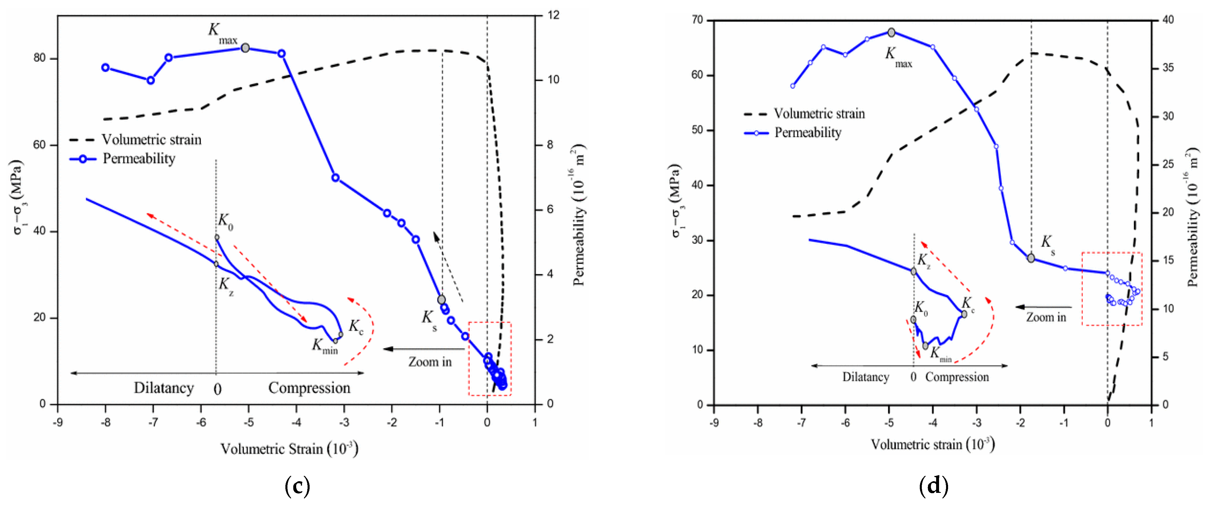
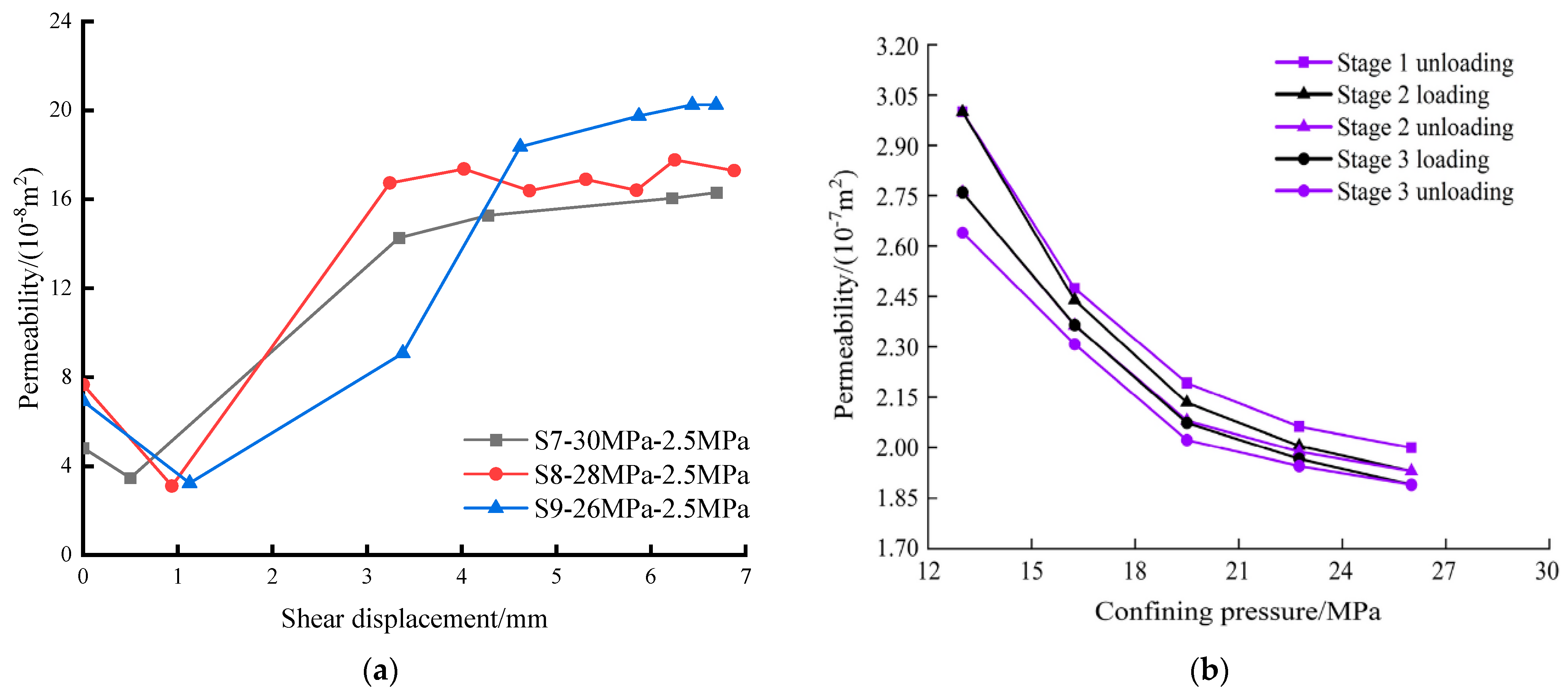
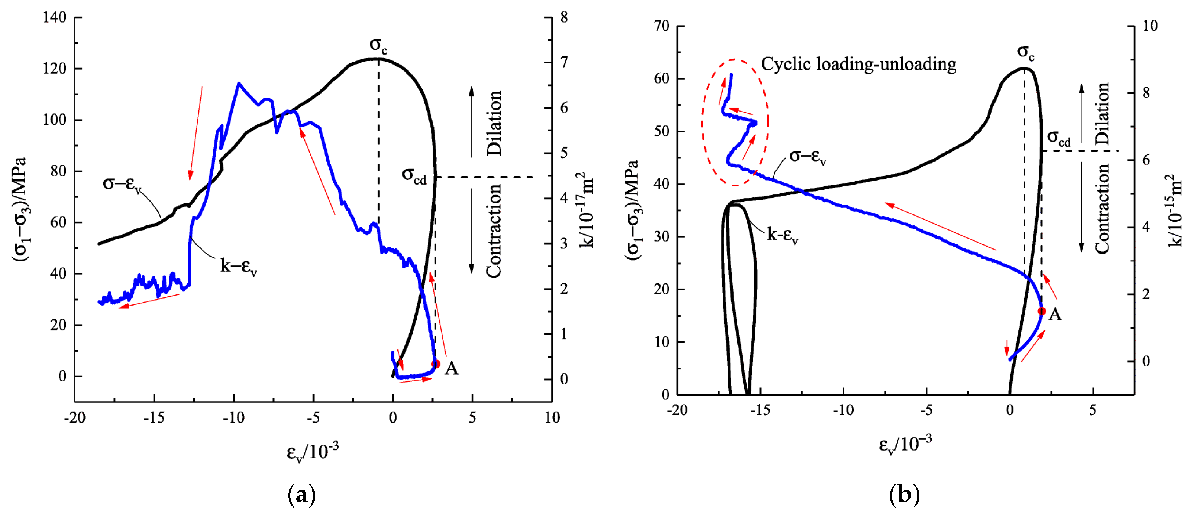
Some studies have studied the permeability evolution of coal and rock during the complete stress–strain process from different perspectives through triaxial seepage tests and shear-seepage tests. Zhao et al. [74] have conducted a triaxial seepage test on fractured Maokou limestone to arrive at the relationship between the permeability of fractured limestone and the variation of volume strain, as shown in Figure 2. It was found that the permeability of fractured tuffs undergoes four stages of slow decrease, gradual increase, rapid increase-small drop, and the above corresponding relationship agrees well at lower permeability pressure (see Figure 2a), while at higher permeability pressure the above corresponding relationship deviates, and the permeability decrease stage is shorter than the volume compression stage (see Figure 2b), indicating the existence of nonlinearity. Zhang et al. [75] conducted triaxial compression seepage tests on fractured granite and slate samples under different confining pressures and explored the evolution process of seepage from linear to nonlinear. Yang et al. [76] conducted cyclic loading unloading shear-seepage coupling tests on fractured sandstone, as shown in Figure 3. The study showed that under the condition of constant normal stress the permeability of rough fractures changes in stages in a “decrease–increase” manner with increasing shear displacement. The relationship between permeability and circumferential pressure is a negative exponential function under cyclic loading and unloading conditions. Jia et al. [77] conducted triaxial seepage tests on volcanic breccias and derived the relationship between permeability and volumetric strain under different water pressures and found the permeability evolves with volumetric strain in different rules, as shown in Figure 4. Alam et al. [78] conducted triaxial tests on three different rocks and found that the permeability of tuff decreased due to pore collapse caused by triaxial compression, the permeability of sandstone decreased due to compaction and large plastic deformation of clay cementitious materials, and the permeability of granite increased by rapture planes and microcracks from biotite. Selvadurai et al. [79] conducted triaxial seepage tests on Cobourg limestone and analyzed its permeability characteristics. Chen et al. [80] conducted a series of triaxial compression tests with permeability measurements to study the mechanical properties of sandstone and the evolution of permeability with damage. The results indicate that the stress–strain curve, permeability evolution curve, and failure mode are significantly influenced by confining pressure, while the influence of pore pressure difference is minimal. Du et al. [81] conducted seepage tests on fractured sandstone with inclined angles and explored the permeability characteristics of single fractured sandstone samples under different filling states. Wang et al. [82] studied the mechanical properties and permeability of sandstone and limestone, and analyzed the mechanical properties and permeability of rock before and after failure. Xiao et al. [83] conducted triaxial compression tests on red sandstone under different seepage pressures, and analyzed the changes in strength, deformation, axial strain stiffness, and permeability during rock failure, and established a permeability and stress evolution model. Huang et al. [84] conducted triaxial compression tests on layered rock masses and analyzed the effect of water pressure on the mechanical properties and permeability of layered rock masses, as shown in Figure 5. The permeability varies among 5, 10, and 13 layers, indicating that rock stratification has a certain impact on permeability. Wang et al. [85] conducted true triaxial loading and unloading tests on coal samples and analyzed the deformation, seepage, damage, strength and damage characteristics of coal specimens. There are many similar experiments, and experimental studies on seepage–stress properties have been conducted by Liu et al. [86], Yang et al. [87], Wang et al. [88], Liu et al. [89], Chen et al. [90], Du et al. [91] and Zhao et al. [92]. Further, in response to rocks’ nonlinear hydromechanical coupling problem [93,94], some scholars have conducted test research, mainly studying the nonlinear characteristics of effective stress in rocks and the nonlinear behavior of seepage during rock deformation. In terms of effective stress, hydromechanical coupling tests conducted on sandstone, limestone and coal rock masses have shown that the effective stress coefficient of rocks is not a constant, but varies with changes in effective confining pressure and pore fluid pressure as well as the strain state, and related research works have been conducted by Ghabezloo et al. [95], Yu et al. [96], and Zhao et al. [97]. In terms of seepage, the non-Darcy flow characteristics of rock post-peak seepage were obtained through hydromechanical coupling tests on rocks and fractured rocks, and the transition process of rock seepage from Darcy to non-Darcy flow was explored, related research works have been conducted by Miao et al. [98], Chen et al. [99], Soni. et al. [100].

3. Hydromechanical Coupling Theory

3.1. Mechanism of Hydromechanical Coupling

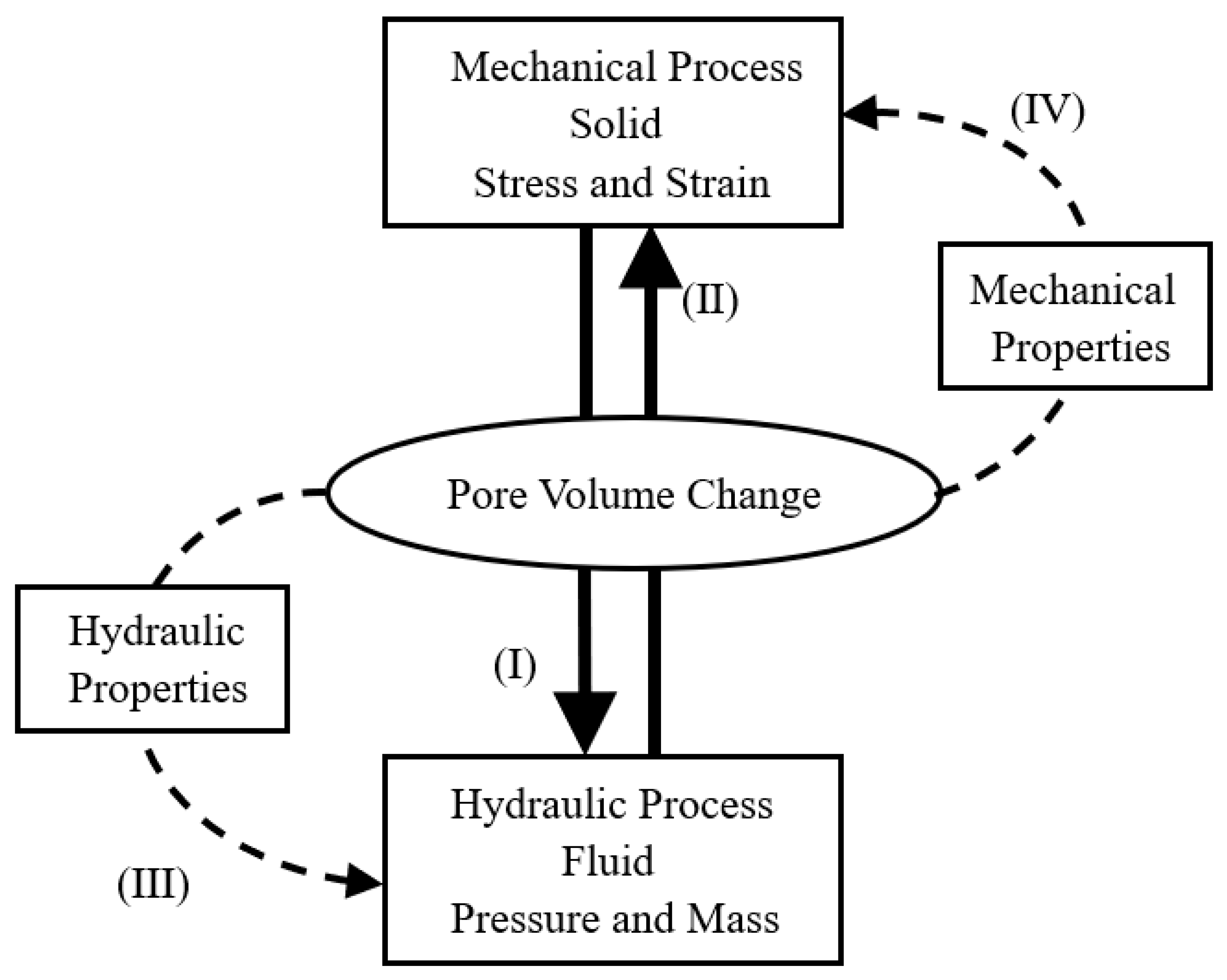
Porous media seepage–stress coupling effects are classified into direct and indirect coupling [2,101,102], as shown in Figure 6. Direct coupling refers to the interaction between solid-phase mechanical deformation and pore-liquid-phase fluid seepage, the essence of which is the change in volume of the gap (pore and fracture) of the rock mass and the interaction between the gap water, including two basic phenomena: (I) the role of solids on fluids, when the rock mass is disturbed to produce deformation, and the balanced state of water in the rock mass fracture is broken, resulting in the water pressure changing while the fluid mass in the fracture is also changing; (II) the fluid to solid action, the pore water pressure changes caused by changes in the volume of fractured porous media. Indirect coupling refers to the change in hydraulic characteristics of rock mass caused by deformation and seepage, which affects the deformation and seepage characteristics of rock mass, including two basic phenomena: (III) The role of solids on fluids, the changes in hydraulic properties caused by stress changes or rock mass deformation, and the most common is the continuous evolution of the permeability coefficient with the stress state and deformation development of the rock mass. (IV) The fluid to solid action, the water pressure changes caused by the change in the effective stress of the rock mass, so as to affect its mechanical properties. The role of direct coupling is more obvious for lower permeability rock masses, while the indirect coupling role is very important for fractured rock masses. (III) and (IV) represent the influence of the seepage field on the stress field, (I) and (II) represent the influence of the stress field on the seepage field. The complete double-field coupling control equation should fully reflect the interaction of the above four aspects of the double-field. When the control equation can reflect the interaction of (I), (II) and (IV) aspects, it is called a fully coupled method. Otherwise, it is called incomplete coupling (loose coupling) analysis. The coupling methods are divided into nonlinear coupling methods and linear coupling methods depending on whether the control equations reflect the action of the (II) aspects.
The establishment of dual-field coupling control equations in a rock mass can be derived using the phenomenological and mixture theory methods from the macroscopic mechanical perspective, as well as the averaging theory (hybrid mixture theory) from the microscopic mechanical perspective [101,103,104].
Generally, the hydromechanical coupling background was taken as the hypothesis [102]:
(a)
Coupling medium only contains a solid rock framework and fluid-water two-phase medium, and the rock framework is a homogeneous isotropic elastomer, the pore is fully saturated by water.
(b)
The influence of the temperature field is not involved.
(c)
Solid deformation is assumed to be small and the acceleration of fluids and solids as well as the inertia force of fluid flow are neglected.
(d)
The stress–strain symbols conform to the elastic mechanics.

3.1.1. Control Equations

Based on the principle of conservation of linear momentum, the equilibrium equation for mixed media is obtained as [102,103]:
S T σ α m p + ρ g = 0
Elastic constitutive relationship of rock skeleton
σ = D ε
According to the conservation of mass in mixed media, the continuity equation can be written as
α m ε ˙ + p ˙ Q + T k μ w p ρ w g = Q
when, ρ = 1 n ρ s + n ρ w , ρ s is the density of the solid (rock mass)skeleton; ρ w is the density of the liquid (water); n is the porosity of the medium; μ w is the viscosity coefficient of the liquid; α is the pore pressure coefficient; Q is the source and sink item; 1 / Q = α n / K s + n / K w ; K s is the bulk modulus of the solid phase medium; K w is the bulk modulus of the liquid; p is the pore water pressure; g is the gravitational acceleration vector; ε is the strain vector, ε = ε x   ε y   ε z   ε x y   ε y z   ε z x T ; σ is the effective stress vector, σ = σ x   σ y   σ z   τ x y   τ y z   τ z x T ; k is the permeability tensor; D is the elastic tensor (for nonlinear problems taken as the tangent D T ); vector m T = 1   1   1   0   0   0 T ; is an operator tensor, = / x   / y   / z   T ; S is an operator tensor, S = x 0 0 0 y 0 0 0 z y 0 z x z 0 0 y x T .
Equations (1)–(3) represent the fully coupled equations of water seepage rock deformation (seepage–stress), reflecting the fully coupled process of double-field between fluid and solid phases, as shown in Figure 1 (I)–(IV).
For two-dimensional problems, when the path (I) is not considered, Equation (3) can be rewritten as
p ˙ Q + T k μ w p ρ w g = Q
When steady flow or without considering water storage release, Equation (4) can be rewritten as
T k μ w p ρ w g = Q
Equation (1), (2), (4), or (5) is the loosely coupled equations of seepage–stress.
In this case, the control equation consists of Equation (1), (2), (4), or (5) and the seepage–stress intrinsic relationship model is the loosely coupled process.

3.1.2. Boundaries and Initial Conditions

Setting the problem region as Ω and the region boundary as Γ, which includes the enforced and natural boundaries of the medium. Specific definition: Γu is the displacement boundary, Γσ is the stress boundary, Γp is the pore water pressure boundary, and Γq is the flow boundary.
The boundary limits are as follows:
Γ = Γ u Γ σ = Γ p Γ q
Γ u Γ σ = Γ p Γ q =
The boundary conditions are:
u = u ¯ ,   on   Γ u   ( Given   displacement   )
Ι T σ = σ ¯ ,   on   Γ σ   ( Given   stress )
p = p ¯ ,   on   Γ p   ( Given   pore   water   pressure )
k μ w p ρ w g = q ¯ ,   on   Γ q   ( Given   flow )
when σ = σ x   σ y   σ z   τ x y   τ y z   τ z x T is the stress vector; u is the displacement vector; n = n x   n y   n z   T is the unit direction vector, Ι = n x 0 0 0 n y 0 0 0 n z n y 0 n z n x n z 0 0 n y n x T ; the symbolic marker ¯ represents the boundary known quantity. The initial condition at the initial moment
t   =   0
u = u 0 ,   p = p 0 ,   in   Ω   and   on   Γ

3.2. Mathematical Modeling Methods

Mathematical modeling methods include the mechanism analysis method, hybrid analysis method and system identification method [105]. The mechanism analysis method is to establish the mathematical model of the dual-field coupling of the rock mass system through the mechanism analysis of the mutual mechanical interaction between rock mass and groundwater, by using the means of mechanics and mathematics. This method is adapted to just the mathematical modeling of simple systems, and the impact of natural or man-made causes on the coupled fields is difficult to describe accurately. The mixed analysis method is based on the mechanism analysis method and combined with the experimental analysis method to study the mechanical mechanism of rock mass systems. This method is widely used in studying the problem of dual-field superposition in rock mass systems. System identification is a method to estimate the mathematical model of the system by measuring the output response of the system under the action of human input, or the input and output data records during normal operation, and performing the necessary data processing and mathematical calculation.

3.3. Mathematical Model of Seepage–Stress Coupling

Since the actual rock mass system research purpose requirements and modeling methods are diverse, determining the mathematical models of coupled seepage and stress fields in rock mass systems are also diverse, and there are some differences in the established models. During the practical application, different mathematical models are selected with specific problems, specific geological conditions and specific engineering needs. Numerous experts and scholars [106,107] have proposed different model classifications by summarizing the hydromechanical coupling models. Liu et al. [101] classified different coupling models into six categories: equivalent continuum model (ECM), fracture network model (FNM), dual-media model (DM), fracture mechanics model (DMM), continuous damage mechanics model (CDM), and statistical models (SMs). Since the equivalent continuous model, the fracture network model and the dual medium model are mainly based on the classical viscoelastic-plastic constitutive model, focusing on the treatment of the seepage field, without considering the changes of the pore and fracture structure system in the rock mass, they are called the classical seepage–stress coupling model. The fracture mechanics model, the continuous damage mechanics model and the statistical model are based on the damage and fracture behavior of the rock mass under the coupling action, focusing on the more complex coupling effect caused by the different qualitative changes in the rock mass structure, so they are also called the seepage-damage coupling model. Here is a brief overview of the research progress, advantages and disadvantages of the above six mathematical models.

3.3.1. Classical Seepage–Stress Coupling Model

Equivalent Continuum Model

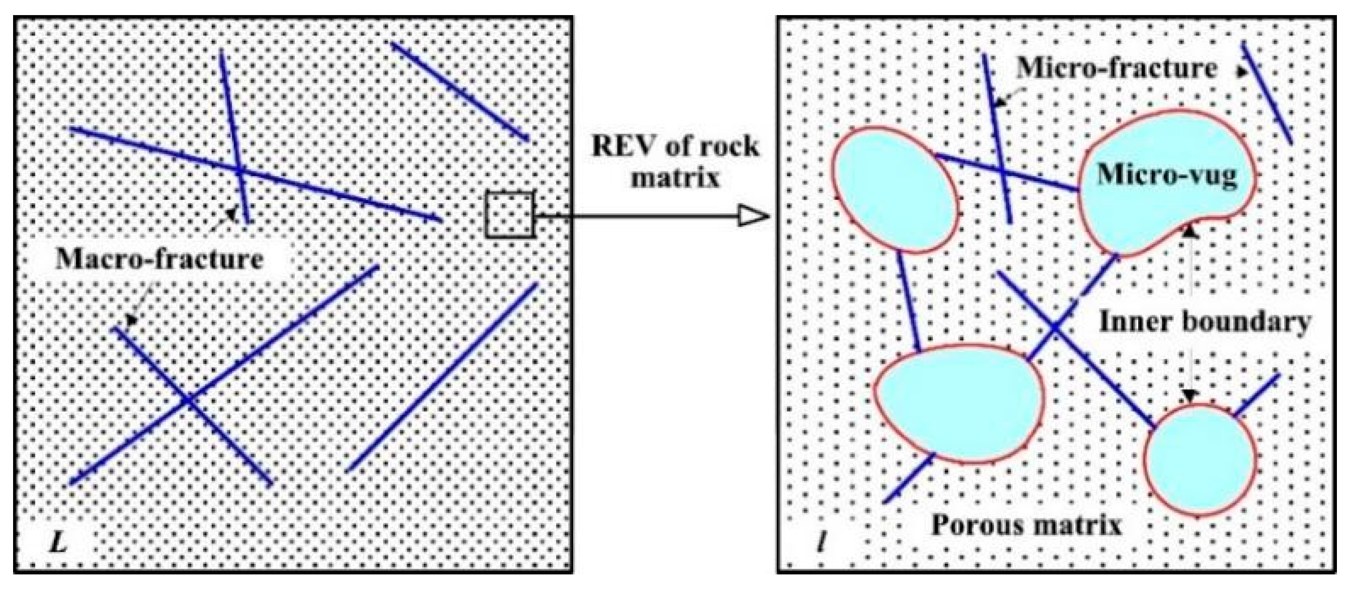
The equivalent continuous medium model, which takes the pore-fracture system as a continuous medium, describes the seepage equation with continuous medium theory. The model does not need to know the geometric and permeability characteristics of each crack but only requires determining the statistical values of the dominant geometric hydraulic parameters in the rock mass. As a result of using a mature continuous medium research method to study seepage–stress coupling of fractured rock mass, the application of this model is very convenient at present. However, the fractured rock mass is equivalent to a continuous medium, which the main water conduction function of the fractured rock mass cannot depict and the real seepage condition in the fractured rock mass cannot gain. When the actual flow rate in the fracture is much larger than that in Darcy’s equivalent continuous medium, especially in the analysis of unsteady flow, the use of the model is limited. Yan et al. [108] utilized an improved equivalent continuity model (ECM) to model micro-cracks and pores, and proposed an effective numerical model for simulating hydraulic mechanical coupling in porous media containing multi-scale cracks and pores (see Figure 7). Song et al. [109] analyzed the stability of fractured rocky slopes by linking the equivalent continuous medium model with the finite element method.

Fracture Network Model

The fracture network model, based on the basic formula of single-fracture seepage flow, combines cubic law and Darcy law to establish the flow balance equation and uses the equal flow of inflow and outflow at the intersection point of each fracture to obtain its head value. The model captures the essential characteristics of fracture seepage and describes the non-uniform anisotropy of fractured rock mass, which can reflect the actual seepage state in the fracture network. When the rock mass is very compact and its permeability can indeed be neglected, the study of seepage state and solute transport law in a small or specific area has incomparable advantages over equivalent continuous media. However, the geometric parameters of all fractures in the research area are difficult to obtain, the calculation amount is large and the operability is not strong, so it is difficult to apply in actual work. Ma et al. [110] introduced a density reduction process for typical discrete fracture network models by considering the correlation index, and the improved equivalent model based on different fracture structures was validated (see Figure 8). Wang et al. [111] introduced the connected fracture network generated by MATLAB into COMSOL Multiphysics to establish a discrete fracture unsaturated seepage–stress-damage coupling model and verified the model by an example.

Dual Media Model

The dual medium model was proposed by Soviet scholar Barrenblatt in 1960, believing that fractures are the main transmission channels for fluids, rock blocks, are the main storage space for fluids, and the pore system (including microcracks) and fracture system of rock blocks continuously fill the entire research area. It characterizes the situation of preferential flow to a certain extent, taking into account the objective energy exchange between rock block pores and rock mass fractures, and studying the fracture network as a continuous medium with strong operability. However, sometimes the typical unit may not exist, or the unit may be too large, and the fracture network is not necessarily equivalent to a continuous medium. and the exchange quantity is difficult to determine accurately when establishing the fracture-pore hydraulic exchange equation, and the accuracy of the model is affected. For complex fracture-pore systems, the simulation workload is large, and corresponding simplification and assumptions need to be made, which limits the applicability of the model. Yan et al. [112] proposed a novel two-dimensional mixed fracture pore seepage model for fluid flow in fractured porous media, considering the influence of dual media. Zhao et al. [113] proposed a dual medium model that includes equivalent continuous and discrete fractured media to study the coupled seepage damage effect in fractured rock masses, as shown in Figure 9.

3.3.2. Seepage-Damage Coupling Model

Fracture Mechanics Model

The fracture mechanics model, considering the deformation of the crack, the evolution of crack length and the area, is estimated by simplified effective crack form through friction slip and stress between crack surfaces in different rock mass and wing crack growth caused by water pressure, thus the permeability is enhanced due to stress expansion of crack [114]. The mechanical mechanism of water pressure on crack growth in the rock mass is a key issue in this model. However, the crack system in rock mass needs to be quantitatively described. It is difficult to describe the local occurrence, propagation and nucleation of multiple random cracks under load and water stress, and to describe the effect of damage such as defects before micro-crack formation on the mechanism of rock action during the coupling process. It is difficult to consider the nucleation between cracks in this model, i.e., the assumption of constant strain, which makes it impossible to consider the interaction between random cracks, resulting in an increase in permeability [114]. Therefore, it can only be used for coupling study of the elastic stage before the rock mass peak. The fracture mechanics model is widely used in hydraulic fracturing/splitting simulation. Bruno et al. [115], respectively, adopted the fracture mechanics method to study the seepage during the whole process of hydraulic fracturing initiation, expansion and closure. Zhao et al. [116] proposed a model for wing joints based on the fracture model, considering the effect of water pressure in the wing joints and the connecting part of the main joints on the stress intensity factor at the tip of the wing joints, which is a combination of hydraulic and far-field stresses.

Continuous Damage Mechanics Model

The continuous damage mechanics model, taking into account the interaction mechanism between micro-cracks that cannot be explained by the fracture mechanics model and the deformation characteristics of the peak and post-peak values of the macro rock mass, makes up for the shortcomings of the fracture mechanics model. This model can simulate the fracture phenomena of various rock masses under the combined action of stress and pore water pressure, including the brittleness, ductility, and creep failure characteristics of the rock mass. However, the model is difficult to reflect the overall damage of the rock body due to localized rupture, and can only predict the damage rupture process of the rock body under the action of two fields in an average sense. Shojaei et al. [117] incorporated the fracture mechanics of microcrack and micropore nucleation and coalescence into the formula of CDM model, and established a constitutive model based on continuous Damage mechanics (CDM) to describe the elastic, plastic and damage behavior of porous rock. Yi et al. [118] established a new fully coupled model for fluid flow and rock damage, considering maximum normal stress and rock permeability.

Statistical Model

The statistical model assumes that the load acting on the entire rock mass is uniform, and the stress applied to each small area is randomly different [119]. The non-uniformity of materials is described by the statistical distribution of various parameters of the material, whether it is a global failure statistical model or a local failure statistical model [114]. The local stress state of any small region can be described by a distribution function. Based on a certain yield and failure criterion, it can be judged whether the area is damaged or not. When more and more small areas are damaged, the final fracture of rock mass will occur. The main feature of the model is to study the constitutive relation of each phase medium in rock mass from the micro perspective and to simulate the coupling effect in rock mass utilizing powerful computer calculation ability, to visually reproduce the micro damage and destruction process of rock mass under the coupling field. Statistical models can be divided into Statistical Continuous Damage Models, Statistical Particle Models and Statistical lattice models. The statistical continuous damage model has a remarkable effect in simulating the anisotropy of rock mass and its inherent random distribution cracks, but it lacks theoretical rigor and its distribution type needs to be combined with macro and micro test results. Zhu [120] used a lattice model to simulate the permeability reduction in expansive high-porosity rock mass under a biased stress load and introduces a damage parameter to reflect the connection between mechanical expansion and hydraulic characteristics of the model.
It should be noted that the above classification methods are not absolute, and there can be other classification methods. These classification methods are not completely isolated and clearly defined and are often cross-applied, DM models have the characteristics of both ECM and FNM models, and CDM models are built based on ECM models, which can be transformed into SM models.

4. Numerical Simulation of Hydromechanical Coupling

As a natural quasi-brittle material, the hydromechanical coupling behavior of rock mass is a challenging field in modern science. With the development of computer technology and numerical methods, numerical simulation methods have gradually entered the geotechnical field and become increasingly mature in recent decades. Significant progress has been made in applying numerical methods to analyze the hydromechanical coupling of rock masses. The commonly used numerical methods for hydromechanical coupling analysis of rock masses mainly include three types [103,121,122]: (1) Method of continuum mechanics: Finite Element Method (FEM), Boundary Element Method (BEM), Finite Difference Method (FDM); (2) Mechanical methods for discontinuous media: Distinct Element Method (DEM), Block Element Method (BEM), Composite Element Method (CEM), Discontinuous Deformation Analysis (DDA); (3) Other numerical methods: Element-free method, numerical manifold element, continuous/discontinuous medium coupling method.

4.1. Continuum Method

4.1.1. Finite Element Method

The finite element method is the most mature and widely used numerical analysis method at present, which has unique advantages in solving continuous small deformation on problems [123]. It divides the complex solution domain into finite units, which are connected by nodes and interact with each other. When solving, first establish the equilibrium equation for each unit, and then form a whole system of equations based on the connection between the units, using boundary conditions to solve unknown quantities for each element and node. Mao et al. [124] used the finite element method to analyze the seepage and stress fields of fractured rock masses. Li et al. [125] established a fully coupled seepage–stress model based on the Extended Finite Element Method (XFEM) to achieve the deflection mechanism of hydraulic fracturing fractures.

4.1.2. Boundary Element Method

The boundary element method (BEM) is a new numerical method developed after the finite element method (FEM), which is different from the basic idea of the finite element method (FEM) in dividing units in the continuum domain [126]. The boundary element method divides units on the boundary of the defined domain and uses functions satisfying the control equation to approximate the boundary conditions. So, the boundary element method has the advantages of fewer unknowns of the unit and simpler data preparation compared with the finite element. However, when the boundary element method is used to solve nonlinear problems, the domain integral corresponding to the nonlinear term is encountered, which has a strong singularity near the singular point, making it difficult to solve. Cheng et al. [127] used the double boundary element method (DBEM) to simulate rock deformation and fluid flow in fractures.

4.1.3. Finite Difference Method

The finite difference method is an old numerical method for solving differential equations with given initial values or boundary values. It converts the problem of solving differential equations into that of solving algebraic equations by using difference equation approximation instead of the differential equation. Due to the absence of the need to form a global matrix and the use of explicit and iterative solving algorithms, it has a good effect on simulating large deformation problems in continuous media and is widely used. Li et al. [128] proposed an elastic-brittle constitutive model considering crack water pressure using FLAC3D to analyze the stability of the right bank slope of the Dagangshan Hydropower Station in Sichuan Province, China (see Figure 10). Fu et al. [129] developed a new coupling model containing fluid pressure and mechanical damage using FLAC3D and applied it to the analysis of seepage evolution, rock deformation, and lining stability during the excavation of the Jiaozhou Bay subsea tunnel.

4.2. Discontinuous Media Method

4.2.1. Discrete Element Method

The discrete element method was proposed by Cundall in 1971 and later developed by Voegele et al. as a new numerical simulation method, it focuses on block systems cut by fracture surfaces and uses Newton’s second law to describe the motion between each block. According to the different shapes of blocks, the discrete element method can be divided into the block discrete element method and the particle discrete element method. Zhang et al. [130] studied the interaction between hydraulic fractures (HFs) and natural fractures (NFs) using an explicit coupled hydrogeological mechanical model in a two-dimensional particle flow code (PFC2D). Chen et al. [131] conduct hydraulic fracturing and seepage–stress coupling analysis on fractured rock masses by using UDEC, respectively.

4.2.2. Block Element Method

The block element method is a discontinuous medium analysis method that considers weak interlayers between rock blocks [132]. It considers that the block does not deform and that the deformation only occurs at the unit connection. Taking the displacement of the centroid of the block element as the basic unknown quantity, the balance equation of the element, the compatibility equation of the displacement of the structural plane block and the element, and the contact mechanics model of the structural plane are established to solve the balance of the block. In terms of hydromechanical coupling analysis. Yin et al. [133] used block element theory to analyze randomly fractured rock masses and wrote corresponding programs. Zhou et al. [134] studied the stability of three-dimensional slopes using the block element method. The principle of the rigid body element method is the same as that of the block element method, which treats blocks as rigid bodies. The only difference is that rigid body elements concretize the contact elements between blocks into springs, without any substantial difference.

4.2.3. Discontinuous Deformation Analysis

Discontinuous Deformation Analysis (DDA) is an analytical method proposed by Dr. Shi Genhua [135] for simulating the mechanics of granular systems. It combines the block theory with the finite element theory. Under the assumed displacement mode, the general equilibrium equation is established by the variational method. By applying or removing the rigid elastic tube at the contact surface, there is no embedment or tension between the blocks. This method takes into account the deformation of the rock block itself. The minimum potential energy principle is introduced to integrate the contact problem between blocks and the deformation problem of the block itself into the matrix solution. It can not only solve the small displacement problem but also has a good effect on the calculation of large deformation. Zhang et al. [136] analyzed the block deformation and hydraulic fracturing under buoyancy and uniform water pressure based on the discontinuous deformation analysis (DDA) water force coupling model and applied it to the sliding stability evaluation of gravity dam foundations. Gao et al. [137] analyzed the water inrush coupling process of fractured rock mass by the DDA method and applied it to tunnel engineering.

4.3. Other Numerical Methods

4.3.1. Numerical Manifold Element Method

The numerical manifold method is a new numerical calculation method proposed by Dr. Shi Genhua in 1992 by using finite element cover technology of manifold analysis in modern mathematical theory. This method absorbs the advantages of finite element and discontinuous deformation, divides units like finite element, ensures the solution accuracy of stress field, and has unique advantages in simulating discontinuous deformation by introducing independent mathematical and physical covering systems. Sun et al. [138] used the numerical manifold element method to simulate the two-phase seepage–stress coupling process in fractured porous media. Li et al. [139] proposed a hydromechanical coupling model based on NMM which was applied in hydraulic fracturing analysis.

4.3.2. Element-Free Method

Additionally known as meshless method, this method is based on a set of discrete field nodes and selects different approximation functions for interpolation or approximation through the weighted residual method. Because only nodes are divided and unit information is not needed, the grid dependence of similar unit methods is avoided in the calculation process. Shen et al. [140] used the element-free method to track crack propagation and conducted a numerical analysis of hydraulic fracturing on rock masses. Gan et al. [141] proposed a coupled model based on element free method (EFM) hydraulic fracturing and applied it to the hydraulic fracturing analysis of high concrete gravity dams.

4.3.3. Continuous/Discontinuous Media Coupling Method

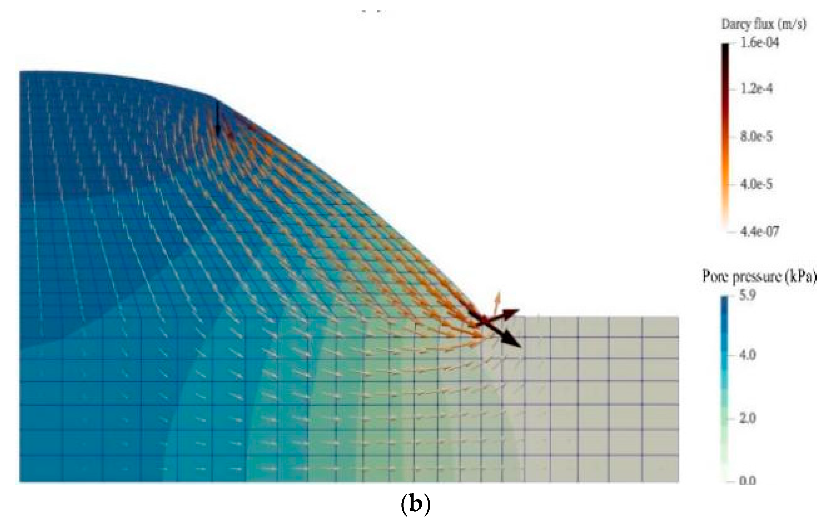
The basic idea of the FEM/DEM coupling method: The finite element mesh is used to discretize the solution domain including the primary crack. The internal part of the unit is calculated by the finite element method. The structural unit or spring description contact is set up between the units by the same treatment as the discrete element. This method can well simulate the behavior of discontinuous media such as the formation, propagation and penetration of cracks in geotechnical materials. In terms of hydromechanical coupling Hu et al. [142] used coupled FEM-DEM method to study post-diffusion and slope failure caused by seepage (see Figure 11). Lisjak et al. [143] used this method to explore the development and application of a fully coupled model of seepage and stress in hydraulic fracturing processes. Furthermore, the FEM/BEM coupling method and DEM/BEM coupling method are also applied to hydraulic coupling analysis [144,145].

5. Engineering Applications

Along with the increasing number of reservoir dams, deep tunnels, high slopes and other projects, and the resulting frequent occurrence of geological hazards, the rock hydromechanical coupling research has received attention and has been applied in many engineering fields.

5.1. Hydromechanical Coupling of Mining Engineering

Hydromechanical coupling problems are involved in coal and gas outbursts, water inrush from confined water floors, water injection from the coal seam, etc. Zhao et al. [146] and Liang et al. [147] have completed systematic and in-depth research to establish a mathematical model of hydromechanical coupling of coal and gas and numerical analysis of the coal and gas outburst process. Lu et al. [148] proposed a damage-seepage coupling simulation method based on micromechanics, and simulated the seepage process of fractures in coal seam floor slate layers. Zhao et al. [149] studied the hydromechanical coupling problem of karst water inrush and high-pressure water injection in coal seams encountered in mines and proposed a dual medium model containing equivalent continuous and discrete fractured media.

5.2. Hydromechanical Coupling Problems of Hydraulic and Hydropower Projects

Conducting seepage–stress coupling analysis in the dam and its surrounding rock mass is the key to solving problems such as evaluating and predicting the stability of the reservoir bank slope and the stability of the dam, dam foundation, and dam abutment. Wang et al. [150] constructed the equivalent continuous medium mathematical model of seepage–stress field coupling and analyzed the deformation of rock mass of hydraulic and hydropower projects under seepage–stress coupling. Xue [151] has conducted a coupling analysis of the seepage field and stress field for fractured rock mass with a drainage hole in the Xiaowan arch dam foundation, which shows that the calculation results under the coupling condition are quite different from those of a single field. The interaction between the two fields cannot be neglected in stability analysis and engineering design.

5.3. Hydromechanical Coupling of Slope Engineering

Slope stability is the most concerning problem in many hydraulic and geotechnical engineering designs. Slope destabilization may result in a landslide, which makes the project unusable and even brings about serious disasters. Chen et al. [152] established a fully coupled numerical model of fluid-solid interaction and analyzed the landslide of Zhongliang Reservoir in Chongqing, China. Bagale et al. [153] established the mathematical model of the slope failure system under the fluid–structure interaction, calculated the slope stability coefficient using the finite element strength reduction method, and analyzed the influence of considering seepage on the slope stability.

5.4. Hydromechanical Coupling in Tunnel Engineering

The surrounding rock of the tunnel is in a coupling state with the surrounding environment when bedrock fractures are well-developed and water-rich, it is easy to cause water to gush into the tunnel. The stability of the tunnel structure and the deformation of the surrounding rock have an important influence on the construction and operation of the tunnel. Fahimifar et al. [154] conducted a seepage–stress coupling analysis of underwater tunnels, providing an analytical solution for tunnel analysis below groundwater level under plane strain axisymmetric conditions, and pointing out that tunnel stability depends on seepage and pore water pressure under high pore pressure gradients. Zhang et al. [155] analyzed the stability of surrounding rock in deep-buried water-rich tunnels under seepage conditions and simulated the changes in seepage–stress during tunnel excavation.

5.5. Hydromechanical Coupling Problems in Energy Extraction and Waste Disposal and Energy Storage

Energy extraction, oil and gas extraction, dry hot rock development, etc., are closely related to hydromechanical coupling research [156]. In the process of energy development, the commonly used hydraulic fracturing technology induces the generation of fractures, which involves the problem of hydromechanical coupling. In the fields of waste disposal and energy storage, both involve closure issues. Studying multi-field coupling models such as seepage, stress, and temperature is of great significance for the disposal of nuclear waste, CO2 geological storage and sealing of oil and gas storage warehouses [157,158].

6. Conclusions and Prospects

A comprehensive overview of the hydromechanical coupling tests, theoretical and numerical methods and engineering applications in rock materials is presented in this paper. As for the current progress of research on the hydraulic coupling of rock materials, there are still many problems that have not been completely solved and deserve further research and discussion, and the author believes that further investigation should be conducted in the following aspects:
(1) For permeability tests, real triaxial seepage shear tests of deeply fractured rocks need to be further investigated and combined with macroscopic, microscopic and trace methods for hydraulic coupling studies of rock materials at different scales to meet the requirements of practical engineering as much as possible [159,160,161,162,163].
(2) In the aspect of coupling theory, the seepage properties of porous media and the relationship between different rock material properties and deformation and other mechanical behaviors are studied from multiple perspectives. The traditional concepts are broken through and new coupling theories and mathematical models are developed to explain and solve the related practical problems [164]. Moreover, the application of an interdisciplinary approach to solving coupled problems is emphasized [165,166,167].
(3) In numerical simulation and engineering applications, it is necessary to develop different numerical methods and efficient algorithms based on different numerical methods to improve the efficiency of model calculations to better guide engineering practice. In addition, numerical simulations of coupling effects of rock masses under high ground stress and high head [168], coupled rheological effects, coupled dynamic properties and other issues should also be studied in-depth.

Author Contributions

Methodology, Y.Z., H.L. and Y.W.; investigation, W.T. and J.L.; formal analysis, Y.L. and X.W.; writing—original draft, Q.L.; funding acquisition, Y.Z.; writing—review and editing, Y.Z. All authors have read and agreed to the published version of the manuscript.

Funding

This research was funded by the National Natural Science Foundation of China (No. 52274118), and Graduate Research and Innovation Projects of Hunan Province (No.CX20221042). All authors have read and agreed to the published version of the manuscript.

Data Availability Statement

The data that support the findings of this study are available from the corresponding author upon reasonable request.

Conflicts of Interest

The authors declare no conflict of interest.

References

  1. Neuzil, C.E. Hydromechanical coupling in geologic processes. Hydrogeol. J. 2003, 11, 41–83. [Google Scholar] [CrossRef]
  2. Rutqvist, J.; Stephansson, O. The role of hydromechanical coupling in fractured rock engineering. Hydrogeol. J. 2003, 11, 7–40. [Google Scholar] [CrossRef] [Green Version]
  3. Bakker, M.; Anderson, E.I. Mechanics of Groundwater Flow, Treatise on Water Science; Elsevier: Amsterdam, The Netherlands, 2011; pp. 115–134. [Google Scholar]
  4. Zhao, Y. Fluid-Solid Coupling Response and Engineering Application of Fractured rock Mass; Science Press: Beijing, China, 2016. [Google Scholar]
  5. Chen, W.; Wan, W.; Zhao, Y.; Peng, W. Experimental Study of the Crack Predominance of Rock-Like Material Containing Parallel Double Fractures under Uniaxial Compression. Sustainability 2020, 12, 5188. [Google Scholar] [CrossRef]
  6. Bandis, S.; Lumsden, A.; Barton, N. Experimental studies of scale effects on the shear behaviour of rock joints. Int. J. Rock Mech. Min. Sci. Géoméch. Abstr. 1981, 18, 1–21. [Google Scholar] [CrossRef]
  7. Selvadurai, A.; Yu, Q. Mechanics of a discontinuity in a geomaterial. Comput. Geotech. 2005, 32, 92–106. [Google Scholar] [CrossRef]
  8. Jaeger, J.C.; Cook, N.G.W. Fundamentals of rock mechanics; Chapman and Hall: London, UK, 1976. [Google Scholar]
  9. Bandis, S.; Lumsden, A.; Barton, N. Fundamentals of rock joint deformation. Int. J. Rock Mech. Min. Sci. Géoméch. Abstr. 1983, 20, 249–268. [Google Scholar] [CrossRef]
  10. Wang, M.; Wan, W.; Zhao, Y. Experimental study on crack propagation and coalescence of rock-like materials with two pre-existing fractures under biaxial compression. Bull. Eng. Geol. Environ. 2020, 79, 3121–3144. [Google Scholar] [CrossRef]
  11. He, M. The future of rock mechanics lies with China: Inaugural editorial for Rock Mechanics. Rock Mech. Bull. 2022, 1, 100010. [Google Scholar] [CrossRef]
  12. Xie, H. Research progress in deep rock mechanics and mining theory. J. Coal Ind. 2019, 44, 1283–1305. [Google Scholar]
  13. Pirayehgar, A.; Dusseault, M.B. The Stress Ratio Effect on Hydraulic Fracturing in the Presence of Natural Fractures. In Proceedings of the 48th U.S. Rock Mechanics/Geomechanics Symposium, Minneapolis, MN, USA, 1–4 June 2014. [Google Scholar]
  14. Jaeger, J.C.; Cook, N.G.W.; Zimmerman, R.W. Fundamentals of Rock Mechanics, 4th ed.; Wiley: Hoboken, HJ, USA, 2007. [Google Scholar]
  15. Liu, R.; Li, B.; Jiang, Y. Critical hydraulic gradient for nonlinear flow through rock fracture networks: The roles of aperture, surface roughness, and number of intersections. Adv. Water Resour. 2016, 88, 53–65. [Google Scholar] [CrossRef]
  16. Zhao, Y.; Zhang, C.; Wang, Y.; Lin, H. Shear-related roughness classification and strength model of natural rock joint based on fuzzy comprehensive evaluation. Int. J. Rock Mech. Min. Sci. 2020, 137, 104550. [Google Scholar] [CrossRef]
  17. Hyung-Mok, K.; Junya, I.; Hideyuki, H. Flow analysis of jointed rock masses basedon excavation-induced transmissivity change of rough joints. Int. J. Rock Mech. Min. Sci. 2004, 41, 959–974. [Google Scholar]
  18. Zhou, W. Advanced Rock Mechanics; Water Resources and Electric Power Press: Beijing, China, 1989; p. 3. [Google Scholar]
  19. Zhao, Y.; Wang, Y.; Wang, W.; Tang, L.; Liu, Q.; Cheng, G. Modeling of rheological fracture behavior of rock cracks subjected to hydraulic pressure and far field stresses. Theor. Appl. Fract. Mech. 2019, 101, 59–66. [Google Scholar] [CrossRef]
  20. Sun, J.; Wang, S. Rock mechanics and rock engineering in China: Developments and current state-of-the-art. Int. J. Rock Mech. Min. Sci. 2000, 37, 447–465. [Google Scholar] [CrossRef]
  21. Li, Y.; Zeng, X.; Lin, Z.; Su, J.; Gao, T.; Deng, R.; Liu, X. Experimental study on phosphate rock modified soil-bentonite as a cut-off wall material. Water Supply 2021, 22, 1676–1690. [Google Scholar] [CrossRef]
  22. Zhang, N.-C.; Zhang, N.; Esterle, J.; Kan, J.-G.; Zhao, Y.-M.; Xue, F. Optimization of gateroad layout under a remnant chain pillar in longwall undermining based on pressure bulb theory. Int. J. Mining Reclam. Environ. 2015, 30, 128–144. [Google Scholar] [CrossRef]
  23. Liu, S.; Nie, Y.; Hu, W.; Ashiru, M.; Li, Z.; Zuo, J. The Influence of Mixing Degree between Coarse and Fine Particles on the Strength of Offshore and Coast Foundations. Sustainability 2022, 14, 9177. [Google Scholar] [CrossRef]
  24. Pan, Y.-H.; Qi, J.-R.; Zhang, J.-F.; Peng, Y.-X.; Chen, C.; Ma, H.-N.; Ye, C. A Comparative Study on Steady-State Water Inflow into a Circular Underwater Tunnel with an Excavation Damage Zone. Water 2022, 14, 3154. [Google Scholar] [CrossRef]
  25. Sun, C.; Sun, M.; Tao, T.; Qu, F.; Wang, G.; Zhang, P.; Li, Y.; Duan, J. Chloride Binding Capacity and Its Effect on the Micro-structure of Mortar Made with Marine Sand. Sustainability 2021, 13, 4169. [Google Scholar] [CrossRef]
  26. Sun, C.; Sun, M.; Tao, T.; Qu, F.; Wang, G.; Zhang, P.; Li, Y.; Duan, J. Chloride-binding capacity of mortars composed of marine sand subjected to external chloride penetration. J. Oceanol. Limnol. 2022, 40, 1462–1471. [Google Scholar] [CrossRef]
  27. Zhu, W.; Gu, S.-Q. Casing mechanism of engineering hazards in a oil field in central China. Environ. Earth Sci. 2012, 70, 869–875. [Google Scholar] [CrossRef]
  28. Yu, W.; Li, K.; Liu, Z.; An, B.; Wang, P.; Wu, H. Mechanical characteristics and deformation control of surrounding rock in weakly cemented siltstone. Environ. Earth Sci. 2021, 80, 337. [Google Scholar] [CrossRef]
  29. Yuan, Z.; Zhao, J.; Li, S.; Jiang, Z.; Huang, F. A Unified Solution for Surrounding Rock of Roadway Considering Seepage, Dilatancy, Strain-Softening and Intermediate Principal Stress. Sustainability 2022, 14, 8099. [Google Scholar] [CrossRef]
  30. Wu, H.; Jia, Q.; Wang, W.; Zhang, N.; Zhao, Y. Experimental Test on Nonuniform Deformation in the Tilted Strata of a Deep Coal Mine. Sustainability 2021, 13, 13280. [Google Scholar] [CrossRef]
  31. Zhao, Y.; Luo, S.; Wang, Y.; Wang, W.; Zhang, L.; Wan, W. Numerical Analysis of Karst Water Inrush and a Criterion for Establishing the Width of Water-resistant Rock Pillars. Mine Water Environ. 2017, 36, 508–519. [Google Scholar] [CrossRef]
  32. Zhang, H.Q.; He, Y.N.; Tang, C.A.; Ahmad, B.; Han, L.J. Application of an Improved Flow-Stress-Damage Model to the Criticality Assessment of Water Inrush in a Mine: A Case Study. Rock Mech. Rock Eng. 2008, 42, 911–930. [Google Scholar] [CrossRef]
  33. Ren, S.; Zhao, Y.; Liao, J.; Liu, Q.; Li, Y. Lugeon Test and Grouting Application Research Based on RQD of Grouting Sections. Sustainability 2022, 14, 12748. [Google Scholar] [CrossRef]
  34. Dai, S.; Wang, F.; Gong, Y.; Hu, P. Application of Material Balance Equation in Productivity Analysis of Coalbed Methane Reservoir. Fresen. Environ. Bull. 2019, 28, 5605–5611. [Google Scholar]
  35. He, S.; Lu, Y.; Li, M. Probabilistic risk analysis for coal mine gas overrun based on FAHP and BN: A case study. Environ. Sci. Pollut. Res. 2022, 29, 28458–28468. [Google Scholar] [CrossRef]
  36. Li, M.; Lv, H.; Lu, Y.; Wang, D.; Shi, S.; Li, R. Instantaneous discharge characteristics and its methane ignition mechanism of coal mine rock damage. Environ. Sci. Pollut. Res. 2022, 29, 62495–62506. [Google Scholar] [CrossRef]
  37. Lu, Y.; Li, H.; Lu, J.; Shi, S.; Wang, G.G.X.; Ye, Q.; Li, R.Q.; Zhu, X. Clean up water blocking damage in coalbed methane res-ervoirs by microwave heating: Laboratory studies. Process Saf. Environ. 2020, 138, 292–299. [Google Scholar] [CrossRef]
  38. Lu, Y.; Liu, Y.; Shi, S.; Wang, G.G.; Li, H.; Wang, T. Micro-particles stabilized aqueous foam for coal spontaneous combustion control and its flow characteristics. Process. Saf. Environ. Prot. 2020, 139, 262–272. [Google Scholar] [CrossRef]
  39. Zhang, J.; Shi, S.; Lu, Y.; You, B.; Wu, F.; Zhang, L.; Xie, Y.; Zhang, J.; Miao, Z. Coal mine gas abnormal emission inducing factors, manifestation emission mechanism. Fresen. Environ. Bull. 2022, 31, 6569–6575. [Google Scholar]
  40. Zhang, J.; Yang, F.; Zhang, R.; He, J.; Xie, Y.; Miao, Z.; Zhang, J. Experimental research on coal seam structure and gas oc-currence influencing factors in Weijiadi mine China. Fresen. Environ. Bull. 2022, 31, 74–80. [Google Scholar]
  41. Zheng, C.; Jiang, B.; Xue, S.; Chen, Z.; Li, H. Coalbed methane emissions and drainage methods in underground mining for mining safety and environmental benefits: A review. Process. Saf. Environ. Prot. 2019, 127, 103–124. [Google Scholar] [CrossRef]
  42. Zeng, X.; Su, J.; Wang, H.; Gao, T. Centrifuge Modeling of Chloride Ions Completely Breakthrough Kaolin Clay Liner. Sustainability 2022, 14, 6976. [Google Scholar] [CrossRef]
  43. Zhang, R.; Tang, P.; Lan, T.; Liu, Z.; Ling, S. Resilient and Sustainability Analysis of Flexible Supporting Structure of Expansive Soil Slope. Sustainability 2022, 14, 12813. [Google Scholar] [CrossRef]
  44. Pariseau, W.; Schmelter, S.; Sheik, A. Mine slope stability analysis by coupled finite element modelling. Int. J. Rock Mech. Min. Sci. 1997, 34, 242.e1–242.e17. [Google Scholar] [CrossRef]
  45. Wang, Y.; Lu, S.; Zi, F.; Tang, H.; Li, M.; Li, X.; Fang, C.; Ikhumhen, H.O. Artificial and Natural Water Bodies Change in China, 2000–2020. Water 2022, 14, 1756. [Google Scholar] [CrossRef]
  46. Feng, T.; Chen, H.; Wang, K.; Nie, Y.; Zhang, X.; Mo, H. Assessment of underground soil loss via the tapering grikes on limestone hillslopes. Agric. Ecosyst. Environ. 2020, 297, 106935. [Google Scholar] [CrossRef]
  47. Luo, X.; Ren, B.; Hursthouse, A.S.; Jiang, F.; Deng, R.; Wang, Z. Source identification and risk analysis of potentially toxic ele-ments (PTEs) in rainwater runoff from a manganese mine (south central Hunan, China). Water Supply 2021, 21, 824–835. [Google Scholar] [CrossRef]
  48. Ren, B.; Wang, C.; Ma, H.; Deng, R.; Zhang, P. Effect of rainfall on Sb release characteristics from smelting slag in rainy south China. Fresen. Environ. Bull. 2016, 25, 4908–4914. [Google Scholar]
  49. Shi, X.; Ren, B.; Hursthouse, A. Source identification and groundwater health risk assessment of PTEs in the stormwater runoff in an abandoned mining area. Environ. Geochem. Health 2021, 44, 3555–3570. [Google Scholar] [CrossRef]
  50. Wang, X.; Ren, B.; Zhou, Y.; Shi, X. Study on the mechanism and kinetics of manganese release from waste manganese ore waste rock under rainfall leaching. Environ. Sci. Pollut. Res. 2021, 29, 5541–5551. [Google Scholar] [CrossRef]
  51. Xie, W.; Ren, B.; Hursthouse, A.; Wang, Z.; Luo, X. Simulation of Manganese Transport in Groundwater Using Visual MOD-FLOW: A Case Study from Xiangtan Manganese Ore Area in Central China. Pol. J. Environ. Stud. 2021, 30, 1409–1420. [Google Scholar] [CrossRef]
  52. Li, X.; Ding, Y.; Liu, Q.; Zhang, Y.; Han, T.; Jing, Z.; Yu, Z.; Li, Q.; Liu, S. Intense Chemical Weathering at Glacial Meltwa-ter-Dominated Hailuogou Basin in the Southeastern Tibetan Plateau. Water 2019, 11, 1209. [Google Scholar] [CrossRef] [Green Version]
  53. Xie, Q.; Ren, B. Pollution and risk assessment of heavy metals in rivers in the antimony capital of Xikuangshan. Sci. Rep. 2022, 12, 14393. [Google Scholar] [CrossRef]
  54. You, B.; Liang, X.; Liang, K. Study on non-coal mine wastewater treatment based on response surface methodology (RSM). Fresen. Environ. Bull. 2019, 28, 6264–6268. [Google Scholar]
  55. You, B.; Xu, J.; Shi, S.; Liu, H.; Lu, Y.; Liang, X. Treatment of coal mine sewage by catalytic supercritical water oxidation. Fresen. Environ. Bull. 2020, 29, 497–502. [Google Scholar]
  56. Zhang, Y.; Ren, B.; Hursthouse, A.S.; Deng, R.; Hou, B. An Improved SWAT for Predicting Manganese Pollution Load at the Soil-Water Interface in a Manganese Mine Area. Pol. J. Environ. Stud. 2018, 27, 2357–2365. [Google Scholar] [CrossRef]
  57. Zhou, S.; Li, N.; Ren, B.; Zhang, P. Release Law of Sb, As, and Hg in Antimony Smelting Slag Under Simulated Acid Rain. Pol. J. Environ. Stud. 2017, 26, 925–933. [Google Scholar] [CrossRef]
  58. Bian, Y.; Wang, C.; Zhu, G.; Ren, B.; Zhang, P.; Hursthouse, A.S. Occurrence and control of N-nitrosodimethylamine in water engineering systems. Environ. Eng. Res. 2018, 24, 1–16. [Google Scholar] [CrossRef] [Green Version]
  59. Li, Y.; Hu, X.; Ren, B. Treatment of antimony mine drainage: Challenges and opportunities with special emphasis on mineral adsorption and sulfate reducing bacteria. Water Sci. Technol. 2016, 73, 2039–2051. [Google Scholar] [CrossRef]
  60. Li, Y.; Xu, Z.; Ma, H.; Hursthouse, A.S. Removal of Manganese(II) from Acid Mine Wastewater: A Review of the Challenges and Opportunities with Special Emphasis on Mn-Oxidizing Bacteria and Microalgae. Water 2019, 11, 2493. [Google Scholar] [CrossRef] [Green Version]
  61. Yu, S.; Mo, Q.; Chen, Y.; Li, Y.; Li, Y.; Zou, B.; Xia, H.; Jun, W.; Li, Z.; Wang, F. Effects of seasonal precipitation change on soil respiration processes in a seasonally dry tropical forest. Ecol. Evol. 2019, 10, 467–479. [Google Scholar] [CrossRef] [Green Version]
  62. He, L.; Xiao, H.; Cui, Y.; Liu, S.; Chen, J. Review of visualisation methods of studying the seepage mechanism in fractured rocks. Geomech. Geophys. Geo-Energy Geo-Resour. 2021, 7, 102. [Google Scholar] [CrossRef]
  63. Louis, C. Study of groundwater flow in jointed rock and its influence on the stability of rock masses. Imperial College Rock Meck. Res. 1969, 10, 10–90. [Google Scholar]
  64. Witherspoon, P.A.; Amick, C.H.; Gale, J.E.; Iwai, K. Observations of a potential size effect in experimental determination of the hydraulic properties of fractures. Water Resour. Res. 1979, 15, 1142–1146. [Google Scholar] [CrossRef] [Green Version]
  65. Barton, N.; Bandis, S.; Bakhtar, K. Strength, deformation and conductivity coupling of rock joints. Int. J. Rock Mech. Min. Sci. Géoméch. Abstr. 1985, 22, 121–140. [Google Scholar] [CrossRef]
  66. Louis, C. Rock Hydraulics in Rock Mechanics; Springer: Vienna, Austria, 1974. [Google Scholar]
  67. Kranzz, R.; Frankel, A.; Engelder, T.; Scholz, C. The permeability of whole and jointed Barre Granite. Int. J. Rock Mech. Min. Sci. Géoméch. Abstr. 1979, 16, 225–234. [Google Scholar] [CrossRef]
  68. Gale, J.E. The effects of fracture type (induced versus natural) on the stress-fracture closure-fracture permeability relationships. In American Rock Mechanics Association (ARMA); OnePetro: Richardson, TX, USA, 1982; pp. 21–78. [Google Scholar]
  69. Esaki, T.; Du, S.; Mitani, Y.; Ikusada, K.; Jing, L. Development of a shear-flow test apparatus and determination of coupled properties for a single rock joint. Int. J. Rock Mech. Min. Sci. 1999, 36, 641–650. [Google Scholar] [CrossRef]
  70. Liu, C.; Chen, C.; Fu, S. Study on seepage characteristics of a single rock fracture under shear stresses. Chin. J. Rock Mech. Eng. 2003, 10, 1651–1655. [Google Scholar]
  71. Rong, G.; Yang, J.; Cheng, L.; Zhou, C. Laboratory investigation of nonlinear flow characteristics in rough fractures during shear process. J. Hydrol. 2016, 541, 1385–1394. [Google Scholar] [CrossRef]
  72. Archambault, G.; Gentier, S.; Riss, J.; Flamand, R. The evolution of void spaces (permeability) in relation with rock joint shear behavior. Int. J. Rock Mech. Min. Sci. 1997, 34, 14.e1–14.e15. [Google Scholar] [CrossRef]
  73. Xiong, X.; Li, B.; Jiang, Y.; Koyama, T.; Zhang, C. Experimental and numerical study of the geometrical and hydraulic characteristics of a single rock fracture during shear. Int. J. Rock Mech. Min. Sci. 2011, 48, 1292–1302. [Google Scholar] [CrossRef]
  74. Zhao, Y.; Tang, J.; Chen, Y.; Zhang, L.; Wang, W.; Wan, W.; Liao, J. Hydromechanical coupling tests for mechanical and permeability characteristics of fractured limestone in complete stress–strain process. Environ. Earth Sci. 2016, 76, 24. [Google Scholar] [CrossRef]
  75. Zhang, X.; Chen, H.; Yao, C.; Yang, J.; Jiang, S.; Jiang, Q.; Zhou, C. Seepage Characteristics of Triaxial Compression-Induced Fractured Rocks under Varying Confining Pressures. Int. J. Géoméch. 2020, 20, 04020160. [Google Scholar] [CrossRef]
  76. Yang, T.; Wang, P.; Wang, S.; Liu, H.; Zhang, Z. Experimental Study on Shear-Seepage Coupling Characteristics of Single Fractured Rock Mass Under Cyclic Loading and Unloading. Rock Mech. Rock Eng. 2022, 56, 2137–2156. [Google Scholar] [CrossRef]
  77. Jia, C.; Xu, W.; Wang, H.; Zhang, Q. Experimental investigation of the mechanical and permeability characteristics of volcanic breccia. Bull. Eng. Geol. Environ. 2020, 80, 599–610. [Google Scholar] [CrossRef]
  78. Alam, A.B.; Niioka, M.; Fujii, Y.; Fukuda, D.; Kodama, J.-I. Effects of confining pressure on the permeability of three rock types under compression. Int. J. Rock Mech. Min. Sci. 2014, 65, 49–61. [Google Scholar] [CrossRef] [Green Version]
  79. Selvadurai, A.P.S.; Głowacki, A. Stress-Induced Permeability Alterations in an Argillaceous Limestone. Rock Mech. Rock Eng. 2017, 50, 1079–1096. [Google Scholar] [CrossRef]
  80. Chen, X.; Yu, J.; Tang, C.; Li, H.; Wang, S. Experimental and Numerical Investigation of Permeability Evolution with Damage of Sandstone Under Triaxial Compression. Rock Mech. Rock Eng. 2017, 50, 1529–1549. [Google Scholar] [CrossRef]
  81. Du, Y.; Li, T.; Wang, B.; Zhang, S.; Li, H.; Zhang, H.; Zhu, Q. Experimental study on mechanical characteristics and permeability evolution during the coupled hydromechanical failure of sandstone containing a filled fissure. Acta Geotech. 2023, 1–21. [Google Scholar] [CrossRef]
  82. Wang, L.; Liu, J.-F.; Pei, J.-L.; Xu, H.-N.; Bian, Y. Mechanical and permeability characteristics of rock under hydro-mechanical coupling conditions. Environ. Earth Sci. 2015, 73, 5987–5996. [Google Scholar] [CrossRef]
  83. Xiao, W.; Zhang, D.; Wang, X. Experimental study on progressive failure process and permeability characteristics of red sandstone under seepage pressure. Eng. Geol. 2020, 265, 105406. [Google Scholar] [CrossRef]
  84. Huang, W.; Wang, H.; Zhang, T.; He, M.; Yan, L. Hydraulic pressure effect on mechanical properties and permeabilities of lay-ered rock mass: An experimental study. Eur. J. Environ. Civ. Eng. 2023, 27, 2422–24331. [Google Scholar] [CrossRef]
  85. Wang, C.; Zhang, D.; Yu, B.; Li, S. Deformation and Seepage Characteristics of Coal Under True Triaxial Loading–Unloading. Rock Mech. Rock Eng. 2023, 56, 2673–2695. [Google Scholar] [CrossRef]
  86. Liu, J.; Liu, Z.; Jiang, G. Stress Evolution in Linear Cutting Tests: Laboratory and Numerical Methods. Sustainability 2022, 14, 11733. [Google Scholar] [CrossRef]
  87. Yang, S.-Q.; Yin, P.-F.; Xu, S.-B. Permeability Evolution Characteristics of Intact and Fractured Shale Specimens. Rock Mech. Rock Eng. 2021, 54, 6057–6076. [Google Scholar] [CrossRef]
  88. Wang, C.; Zhao, Y.; Ning, L.; Bi, J. Permeability evolution of coal subjected to triaxial compression based on in-situ nuclear magnetic resonance. Int. J. Rock Mech. Min. Sci. 2022, 159, 105213. [Google Scholar] [CrossRef]
  89. Liu, Y.; Yin, G.; Zhang, D.; Li, M.; Deng, B.; Liu, C.; Zhao, H.; Yin, S. Directional permeability evolution in intact and fractured coal subjected to true-triaxial stresses under dry and water-saturated conditions. Int. J. Rock Mech. Min. Sci. 2019, 119, 22–34. [Google Scholar] [CrossRef]
  90. Chen, Y.; Xu, J.; Peng, S.; Zhang, Q.; Chen, C. Strain localisation and seepage characteristics of rock under triaxial compression by 3D digital image correlation. Int. J. Rock Mech. Min. Sci. 2022, 152, 105064. [Google Scholar] [CrossRef]
  91. Du, Y.; Li, T.; Li, W.; Ren, Y.; Wang, G.; He, P. Experimental Study of Mechanical and Permeability Behaviors During the Failure of Sandstone Containing Two Preexisting Fissures Under Triaxial Compression. Rock Mech. Rock Eng. 2020, 53, 3673–3697. [Google Scholar] [CrossRef]
  92. Zhao, Y.; Liu, Q.; Tang, L.; Liao, J.; Chang, L.; Wang, X.; Li, Y.; Ren, S. Test Study of Seepage Characteristics of Coal Rock under Various Thermal, Hydraulic, and Mechanical Conditions. Machines 2022, 10, 1012. [Google Scholar] [CrossRef]
  93. Wang, C.; Jiang, Y.; Liu, R.; Wang, C.; Zhang, Z.; Sugimoto, S. Experimental Study of the Nonlinear Flow Characteristics of Fluid in 3D Rough-Walled Fractures During Shear Process. Rock Mech. Rock Eng. 2020, 53, 2581–2604. [Google Scholar] [CrossRef]
  94. Yu, B.; Chen, Z.; Ding, Q.; Wang, L. Non-Darcy flow seepage characteristics of saturated broken rocks under compression with lateral constraint. Int. J. Min. Sci. Technol. 2016, 26, 1145–1151. [Google Scholar] [CrossRef]
  95. Ghabezloo, S.; Sulem, J.; Guédon, S.; Martineau, F. Effective stress law for the permeability of a limestone. Int. J. Rock Mech. Min. Sci. 2009, 46, 297–306. [Google Scholar] [CrossRef] [Green Version]
  96. Yu, B.; Zhang, D.; Xu, B.; Li, M.; Liu, C.; Xiao, W. Experimental study on the effective stress law and permeability of damaged sandstone under true triaxial stress. Int. J. Rock Mech. Min. Sci. 2022, 157, 105169. [Google Scholar] [CrossRef]
  97. Zhao, Y.; Hu, Y. Experimental Study of the Law of Effective Stress by Methane Pressure. Chin. J. Geotech. Eng. 1995, 3, 26–31. [Google Scholar]
  98. Chen, Y.; Lian, H.; Liang, W.; Yang, J.; Nguyen, V.P.; Bordas, S.P. The influence of fracture geometry variation on non-Darcy flow in fractures under confining stresses. Int. J. Rock Mech. Min. Sci. 2018, 113, 59–71. [Google Scholar] [CrossRef]
  99. Miao, X.; Chen, Z.; Mao, X.; Chen, R. The Bifurcation of Non-Darcy Flow in Post-Failure RockActa Mech. Ph. D. Thesis, China University of Mining and Technology, Xuzhou, China, 2003; pp. 660–667. [Google Scholar]
  100. Soni, J.; Islam, N.; Basak, P. An experimental evaluation of non-Darcian flow in porous media. J. Hydrol. 1978, 38, 231–241. [Google Scholar] [CrossRef]
  101. Liu, Z.; Zhang, Q. A review on the state of art of the saturated seepage-stress coupling models in rock mass. Adv. Mech. 2008, 38, 587–600. [Google Scholar]
  102. Wang, H. Theory of Linear Poroelasticity; Princeton University Press: Princeton, NJ, USA, 2000. [Google Scholar]
  103. Li, G.; Tang, C.; Li, L. Advances in rock deformation and failureprocess under water-rock coupling. Adv. Mech. 2012, 42, 593–619. [Google Scholar]
  104. Zhao, Y.; Chen, M. Fully coupled dual-porosity model for anisotropic formation. Int. J. Rock Mech. Min. Sci. 2006, 43, 1128–1133. [Google Scholar] [CrossRef] [Green Version]
  105. Wu, Y.; Zhang, Z. Introduction to Hydraulics of Rock Mass; Southwest Jiaotong University Press: Chengdu, China, 1994. [Google Scholar]
  106. Wu, Y. Types of rock mass structure and hydromechanical models in rock mass. Chin. J. Rock Mech. Eng. 2000, 6, 687–691. [Google Scholar]
  107. Zhao, Y. Coupling Theory of Seepage-Damage-Fractureinfractured Rock Masses and Its Application. Ph. D. Thesis, Central South University, Changsha, China, 2009. [Google Scholar]
  108. Yan, X.; Huang, Z.; Yao, J.; Zhang, Z.; Liu, P.; Li, Y.; Fan, D. Numerical simulation of hydro-mechanical coupling in fractured vuggy porous media using the equivalent continuum model and embedded discrete fracture model. Adv. Water Resour. 2019, 126, 137–154. [Google Scholar] [CrossRef]
  109. Song, J.; Dong, M.; Koltuk, S.; Hu, H.; Zhang, L.; Azzam, R. Hydro-mechanically coupled finite-element analysis of the stability of a fractured-rock slope using the equivalent continuum approach: A case study of planned reservoir banks in Blaubeuren, Germany. Hydrogeol. J. 2017, 26, 803–817. [Google Scholar] [CrossRef]
  110. Ma, G.; Li, T.; Wang, Y.; Chen, Y. The equivalent discrete fracture networks based on the correlation index in highly fractured rock masses. Eng. Geol. 2019, 260, 105228. [Google Scholar] [CrossRef]
  111. Wang, S.-H.; Yang, T.-J.; Zhang, Z.; Sun, Z.-H. Unsaturated seepage–stress–damage coupling and dynamic analysis of stability on discrete fractured rock slope. Environ. Earth Sci. 2021, 80, 587–600. [Google Scholar] [CrossRef]
  112. Yan, C.; Fan, H.; Huang, D.; Wang, G. A 2D mixed fracture–pore seepage model and hydromechanical coupling for fractured porous media. Acta Geotech. 2021, 16, 3061–3086. [Google Scholar] [CrossRef]
  113. Zhao, Y.; Liu, Q.; Zhang, C.; Liao, J.; Lin, H.; Wang, Y. Coupled seepage-damage effect in fractured rock masses: Model development and a case study. Int. J. Rock Mech. Min. Sci. 2021, 144, 104822. [Google Scholar] [CrossRef]
  114. Yuan, S.; Harrison, J. A review of the state of the art in modelling progressive mechanical breakdown and associated fluid flow in intact heterogeneous rocks. Int. J. Rock Mech. Min. Sci. 2006, 43, 1001–1022. [Google Scholar] [CrossRef]
  115. Bruno, M.; Nakagawa, F. Pore pressure influence on tensile fracture propagation in sedimentary Rock Int. J. Rock Mech. Min. Sci. Géoméch. Abstr. 1991, 28, 261–273. [Google Scholar] [CrossRef]
  116. Zhao, Y.-L.; Cao, P.; Wang, W.-J.; Wan, W.; Chen, R. Wing crack model subjected to high hydraulic pressure and far field stresses and its numerical simulation. J. Central South. Univ. 2012, 19, 578–585. [Google Scholar] [CrossRef]
  117. Shojaei, A.; Taleghani, A.D.; Li, G. A continuum damage failure model for hydraulic fracturing of porous rocks. Int. J. Plast. 2014, 59, 199–212. [Google Scholar] [CrossRef]
  118. Yi, L.-P.; Li, X.-G.; Yang, Z.-Z.; Waisman, H. A fully coupled fluid flow and rock damage model for hydraulic fracture of porous media. J. Pet. Sci. Eng. 2019, 178, 814–828. [Google Scholar] [CrossRef]
  119. Scholz, C.H. Microfracturing and the inelastic deformation of rock in compression. J. Geophys. Res. Atmos. 1968, 73, 1417–1432. [Google Scholar] [CrossRef]
  120. Zhu, W.; Wong, T.-F. Permeability reduction in a dilating rock: Network modeling of damage and tortuosity. Geophys. Res. Lett. 1996, 23, 3099–3102. [Google Scholar] [CrossRef]
  121. Liu, G.; Zhao, H.; Ma, F.; Feng, X.; Guo, J.; Wang, H. Present situation and prospect of seepage stress couplingin fractured rock mass. J. Eng. Geol. 2017, 13, 236–247. [Google Scholar]
  122. Jing, L.; Hudson, J.A. Numerical methods in rock mechanics. Int. J. Rock Mech. Min. Sci. 2002, 39, 409–427. [Google Scholar] [CrossRef]
  123. Hughes, T. The Finite Element Method; Dover: New York, NY, USA, 1987. [Google Scholar]
  124. Mao, H.T.; Wang, X.J. Solid-Liquid Coupling Mechanism Research in Seepage Field and Stress Field of Fractured Rock Mass. Adv. Mater. Res. 2012, 542–543, 1087–1090. [Google Scholar] [CrossRef]
  125. Li, J.; Dong, S.; Hua, W.; Yang, Y.; Li, X. Numerical Simulation on Deflecting Hydraulic Fracture with Refracturing Using Extended Finite Element Method. Energies 2019, 12, 2044. [Google Scholar] [CrossRef] [Green Version]
  126. Becker, A. The Boundary Element Method in Engineering; McGraw-Hill: Berkshire, UK, 1992. [Google Scholar]
  127. Cheng, S.; Zhang, M.; Zhang, X.; Wu, B.; Chen, Z.; Lei, Z.; Tan, P. Numerical study of hydraulic fracturing near a wellbore using dual boundary element method. Int. J. Solids Struct. 2022, 239–240, 111479. [Google Scholar] [CrossRef]
  128. Li, Y.; Zhou, H.; Zhu, W.; Li, S.; Liu, J. Numerical investigations on slope stability using an elasto-brittle model considering fracture water pressure. Arab. J. Geosci. 2015, 8, 10277–10288. [Google Scholar] [CrossRef]
  129. Fu, J.; Cheng, H.; Hou, R.; Labuz, J.; Zhu, W. Simulating progressive failure in fractured saturated rock under seepage condition using a novel coupled model and the application. Geomech. Geophys. Geo-Energy Geo-Resour. 2022, 8, 42. [Google Scholar] [CrossRef]
  130. Zhang, L.; Zhou, J.; Braun, A.; Han, Z. Sensitivity analysis on the interaction between hydraulic and natural fractures based on an explicitly coupled hydro-geomechanical model in PFC2D. J. Petrol. Sci. Eng. 2018, 167, 638–653. [Google Scholar] [CrossRef]
  131. Chen, W.; Konietzky, H.; Liu, C.; Tan, X. Hydraulic fracturing simulation for heterogeneous granite by discrete element meth-od. Comput. Geotech. 2018, 95, 1–15. [Google Scholar] [CrossRef]
  132. Ren, Q. Rigid Body Element Method and Its Application in Stability Analysis of Rock Mass. J. H ohai. Univ. 1995, 1, 1–7. [Google Scholar]
  133. Yin, D.; Wang, W.; Chen, S. Block element method for seepage-stress coupling in random fractured Rock. Rock Soil Mech. 2011, 32, 2861–2866. [Google Scholar]
  134. Zhou, J.-F.; Qin, C.-B. A novel procedure for 3D slope stability analysis: Lower bound limit analysis coupled with block element method. Bull. Eng. Geol. Environ. 2019, 79, 1815–1829. [Google Scholar] [CrossRef]
  135. Ishigenhua; Pei, J. Numerical Manifold Method and Discontinuous Deformation Analysis; Tsinghua University Press: Beijing, China, 1997. [Google Scholar]
  136. Zhang, Q.-H.; Shi, G.-H. Verification of a DDA-based hydro-mechanical model and its application to dam foundation stability analysis. Int. J. Rock Mech. Min. Sci. 2021, 138, 104627. [Google Scholar] [CrossRef]
  137. Gao, J.; Peng, S.; Chen, G.; Mitani, Y.; Fan, H. Coupled hydro-mechanical analysis for water inrush of fractured rock masses using the discontinuous deformation analysis. Comput. Geotech. 2023, 156, 105247. [Google Scholar] [CrossRef]
  138. Sun, H.; Xiong, F.; Wu, Z.; Ji, J.; Fan, L. An extended numerical manifold method for two-phase seepage–stress coupling process modelling in fractured porous medium. Comput. Methods Appl. Mech. Eng. 2022, 391, 114514. [Google Scholar] [CrossRef]
  139. Li, G.; Wang, K.; Tang, C.; Qian, X. An NMM-based fluid-solid coupling model for simulating rock hydraulic fracturing process. Eng. Fract. Mech. 2020, 235, 107193. [Google Scholar] [CrossRef]
  140. Shen, Z.; Zhang, X.; Sun, Y. Research on stress-seepage-damage coupling model of hydraulic fracturing for rock mass. Chin. J. Comput. Mech. 2009, 26, 523–528. [Google Scholar]
  141. Gan, L.; Zhang, K.; Zhang, H.; Tian, Z. Coupling analysis of hydraulic fracturing computation base on element-free method. Clust. Comput. 2017, 20, 3213–3224. [Google Scholar] [CrossRef]
  142. Hu, Z.; Yang, Z.; Guo, N.; Zhang, Y. Multiscale modeling of seepage-induced suffusion and slope failure using a coupled FEM–DEM approach. Comput. Methods Appl. Mech. Eng. 2022, 398, 115177. [Google Scholar] [CrossRef]
  143. Lisjak, A.; Tatone, B.; Kaifosh, P.; He, L. Development of a fully-coupled, hydro-mechanical model for finite-discrete element simulations of fluid-driven fracturing. In Proceedings of 50th US Rock Mechanics/Geomechanics Symposium, Houston, TX, USA, 26–29 June 2016. [Google Scholar]
  144. Fang, S.; Cheng, L.; Ayala, L.F. A coupled boundary element and finite element method for the analysis of flow through fractured porous media. J. Pet. Sci. Eng. 2017, 152, 375–390. [Google Scholar] [CrossRef]
  145. Lorig, L.; Brady, B.; Cundall, P. Hybrid distinct element-boundary element analysis of jointed Rock. Int. J. Rock Mech. Min. Sci. Géoméch. Abstr. 1986, 23, 303–312. [Google Scholar] [CrossRef]
  146. Zhao, Y. Coupled mathematical model on coal mass-methane and its numerical method. Chin. J. Rock Mech. Eng. 1994, 3, 229–239. [Google Scholar]
  147. Liang, B.; Zhang, M.; Wang, Y. Mathematical model and numerical method for coupled gas flow in coal seams and coal defor-mation. Chin. J. Rock Mech. Eng. 1996, 2, 40–47. [Google Scholar]
  148. Lu, Y.; Wang, L. Numerical simulation of mining-induced fracture evolution and water flow in coal seam floor above a confined aquifer. Comput. Geotech. 2015, 67, 157–171. [Google Scholar] [CrossRef]
  149. Zhao, Y.; Liao, J.; Liu, Q.; Li, Y.; Cheng, J. Linkage Analysis between Solid-Fluid Coupling and the Strength Reduction Method for Karst Cave Water Inrush in Mines. Shock. Vib. 2020, 2020, 5415812. [Google Scholar] [CrossRef]
  150. Wang, H.L.; He, M. Arch Dam and Skewback and Dam Abutment Rock Mass Deformation under Seepage Field and Stress Field Coupling. Procedia Environ. Sci. 2012, 12, 561–567. [Google Scholar] [CrossRef] [Green Version]
  151. Xue, L. Analysis of coupled seepage and stress in Xiaowanarch dam foundation with drainage holes. Eng. J. Wuhan Univ. 2013, 46, 290–294. [Google Scholar]
  152. Chen, X.; Huang, B.; Li, B.; Jiang, X. Risk assessment study on landslide-generated impulse waves: Case study from Zhongliang Reservoir in Chongqing, China. Bull. Eng. Geol. Environ. 2022, 81, 158. [Google Scholar]
  153. Bagale, M. The Basic Theory of Fluid-Solid Coupling And Dam Slope Stability Analysis. Int. J. Sci. Technol. Res. 2012, 1, 7. [Google Scholar]
  154. Fahimifar, A.; Zareifard, M.R. A theoretical solution for analysis of tunnels below groundwater considering the hydraulic–mechanical coupling. Tunn. Undergr. Space Technol. 2009, 24, 634–646. [Google Scholar] [CrossRef]
  155. Zhang, J.; Li, S.; Zhang, Q.; Zhang, X.; Li, P.; Wang, D.; Weng, X. Mud inrush flow mechanisms: A case study in a water-rich fault tunnel. Bull. Eng. Geol. Environ. 2019, 78, 6267–6283. [Google Scholar] [CrossRef]
  156. Gong, G.; Zhao, G.; Pang, W.; Yang, M.; Chen, B.; Zheng, J.-N. Review of hydrate-bearing sediment permeability for natural gas hydrate exploitation: Measurement and application development. J. Pet. Sci. Eng. 2023, 220, 111217. [Google Scholar] [CrossRef]
  157. Sun, H.; Li, Z.; Jiao, Y. Study on a coupled thermal-hydraulic-mechanical model in heavy oil reservoir exploitation and its ap-plication. Rock Soil Mech. 2007, 28, 2560–2564. [Google Scholar]
  158. Li, M.; Wang, G.; Cheng, W.; Pu, S.; NI, H.; Shi, X. Heat-fluid-solid coupling mechanism of supercritical carbon dioxide jet in rock-breaking. Pet. Explor. Dev. 2021, 48, 1450–1461. [Google Scholar] [CrossRef]
  159. Li, D.; Liu, Z.; Zhu, Q.; Zhang, C.; Xiao, P.; Ma, J. Quantitative Identification of Mesoscopic Failure Mechanism in Granite by Deep Learning Method Based on SEM Images. Rock Mech. Rock Eng. 2023, 1–22. [Google Scholar] [CrossRef]
  160. Kamel, K.E.M.; Gerard, P.; Colliat, J.-B.; Massart, T.J. Modelling stress-induced permeability alterations in sandstones using CT scan-based representations of the pore space morphology. Int. J. Rock Mech. Min. Sci. 2021, 150, 104998. [Google Scholar] [CrossRef]
  161. Zhang, Y.; Ye, J.; Li, P. Flow Characteristics in a 3D-Printed Rough Fracture. Rock Mech. Rock Eng. 2022, 55, 4329–4349. [Google Scholar] [CrossRef]
  162. Cai, Q.; Huang, B.; Zhao, X.; Xing, Y.; Liu, S. Experimental Investigation on the Morphology of Fracture Networks in Hydraulic Fracturing for Coal Mass Characterized by X-ray Micro-Computed Tomography. Rock Mech. Rock Eng. 2023, 56, 2551–2571. [Google Scholar] [CrossRef]
  163. Zhu, H.; Garg, A.; Yu, X.; Zhou, H.W. Editorial for Internet of Things (IoT) and Artificial Intelligence (AI) in geotechnical engineering. J. Rock Mech. Geotech. Eng. 2022, 14, 1025–1027. [Google Scholar] [CrossRef]
  164. Liu, J.; Xue, Q. Theory of coupled T-H-M processes of rock and soil media and its application in mining engineering. J. Wuhan Poly. Univ. 2004, 3, 55–60. [Google Scholar]
  165. Li, Y.; Huang, R. Relationship between joint roughness coefficient and fractal dimension of rock fracture surfaces. Int. J. Rock Mech. Min. Sci. 2015, 75, 15–22. [Google Scholar] [CrossRef] [Green Version]
  166. Sui, L.; Yu, J.; Cang, D.; Miao, W.; Wang, H.; Zhang, J.; Yin, S.; Chang, K. The fractal description model of rock fracture networks characterization. Chaos Solitons Fractals 2019, 129, 71–76. [Google Scholar] [CrossRef]
  167. Yin, P.; Zhao, C.; Ma, J.; Yan, C.; Huang, L. Experimental study of non-linear fluid flow though rough fracture based on fractal theory and 3D printing technique. Int. J. Rock Mech. Min. Sci. 2020, 129, 104293. [Google Scholar] [CrossRef]
  168. Yan, B.; Guo, Q.; Ren, F.; Cai, M. Modified Nishihara model and experimental verification of deep rock mass under the water-rock interaction. Int. J. Rock Mech. Min. Sci. 2020, 128, 104250. [Google Scholar] [CrossRef]
Figure 1. Different types of rock specimens with (a) complete rock specimens (without artificial prefabricated cracks); (b)prefabricated fractured rock specimens; (c,d) prefabricated fractured rock specimens with inclination; (e) rock specimens with bedding joints.
Water 15 02309 g001
Figure 2. The permeability−strain and volume−strain curves during complete stress−strain at confining pressure equal to 17 MPa; (a) permeability water pressure difference at 2 MPa; (b) permeability water pressure difference at 14 MPa; (c) permeability−volumetric strain curves at 2 MPa; (d) permeability−volumetric strain curves at 14 MPa [74].
Water 15 02309 g002aWater 15 02309 g002b
Figure 3. Triaxial seepage and cyclic loading unloading shear−seepage test curves of fractured sandstone; (a) the relationship between permeability and shear displacement; (b) the relationship between permeability and confining pressure [76].
Water 15 02309 g003
Figure 4. The permeability−volume strain curves during complete stress−strain at confining pressure at 6 MPa; (a) permeability water pressure difference at 1.5 MPa; (b) permeability water pressure difference at 4.5 MPa [77].
Water 15 02309 g004
Figure 5. The change curve of permeability of layered rocks with axial strain [84].
Water 15 02309 g005
Figure 6. Schematic diagram of fluid seepage—porous media deformation coupling mechanism [2].
Water 15 02309 g006
Figure 7. The model construction process [108].
Water 15 02309 g007
Figure 8. Meshes generated in fracture-matrix domain with different extent of fracture reduction: (a) domain with 0% of the total fracture neglected; (b) domain with 90% of the total fracture neglected; (c) neglecting 0% of the total cracks in the crack matrix domain, there are fewer cracks in the region; (d) neglecting 90% of the total cracks in the crack matrix domain with fewer cracks [110].
Water 15 02309 g008
Figure 9. Basic principle of dual-medium seepage-damage coupling model: (a) basic idea of seepage calculation, (b) seepage–stress coupling in discrete fracture medium, and (c) seepage-damage coupling in an equivalent continuous medium [113].
Water 15 02309 g009
Figure 10. Subsea tunnel excavation process is simulated by the designed prefabricated random fracture network [128].
Water 15 02309 g010
Figure 11. Slope stability analysis simulation process: (a) coupling procedure of the FEM–DEM approach; (b) pore pressure and flow velocity contours [142].
Water 15 02309 g011aWater 15 02309 g011b
Disclaimer/Publisher’s Note: The statements, opinions and data contained in all publications are solely those of the individual author(s) and contributor(s) and not of MDPI and/or the editor(s). MDPI and/or the editor(s) disclaim responsibility for any injury to people or property resulting from any ideas, methods, instructions or products referred to in the content.