Abstract
Gravity water delivery systems are common around the world to transport water without the use of external energy. The systems’ inadequate design and operation tend to form entrapped air bodies in downward pipeline lengths. Entrapped air generates considerable energy losses when there are no air admission-expulsion valves or due to valve failures. Air removal by hydraulic means has been modeled under various pipeline diameters, downward slopes, and air volume conditions. However, no generic entrapped air removal models exist, and the study in small diameters (≤50 mm) is limited. Most of the models reported in the literature were obtained for diameters greater than 50 mm, presenting notorious discrepancies among each other. In this research, the entrapped air removal in small diameter pipelines was studied (12.7, 15.875, 19.05, 25.4, 31.75, and 38.1 mm), highlighting the importance of the joint study of the air bubbles’ removal by the turbulent action of a hydraulic jump downstream of an air body and the consequent removal of remaining entrapped air by a hydrodynamic thrust. Potential models were found for the air bubbles’ removal for different pipeline diameters and downward slopes. Linear relationships were found between the dimensionless air removal parameter and the pipeline’s downward slope.
1. Introduction
Entrapped air in pipelines represents a constant threat to the proper operation of gravity water systems [1]. The problems produced by entrapped air in gravity water systems can have mild effects, including sudden pressure variations or flow decrease, and severe effects such as acting as vibrations along the system, complete flow blockage, and damages in pipelines and components of the system such as fittings, valves, filters, pumps, etcetera [1,2,3]. The damage induced by entrapped air depends on the air body’s location, size, ability to move, system setup, and flow regime (steady-state or transient condition) [1].
The entrapped air can be present as small-scale bubbles and large-scale pockets along the pipeline [1]. The size of the air bodies varies greatly throughout the system. Dissolved air is one of the most common sources introducing entrapped air in pipes; the air content depends on the pressure and temperature [3]. The water contains approximately 2% of dissolved air by volume [4,5]. Another source of entrapped air within water systems is air entrainment from the atmosphere, which can be confined in the pipelines through pump inlets, malfunctioning air valves, and leaky system components, as described above [6]. Air vacuum valves are often not the final solution to remove entrapped air from water delivery systems.
The entrapped air in a pressurized pipeline system is hydraulically removed by: (1) the turbulence that causes a submerged hydraulic jump, (2) the hydrodynamic thrust over an entrapped air volume, (3) the slippage that imposes a water–air shear force in a free surface flow, and (4) the action of a water push over the entrapped air in the pipe cross-section, similar to a piston in a compression chamber [7].
Entrapped air formation is mainly caused due to an inadequate design and operation of water delivery systems [8]. Air formation in close conduits is still a common phenomenon among water systems design. Most design criteria do not consider the entrapped air scenario; in many cases it is entirely neglected by designers [5]. In order to ensure successful maintenance, operation, and reparation procedures, the planning of the water distribution system must consider the effects of entrapped air bodies [9].
In the design of gravity water delivery systems, it is assumed that the pipelines will be completely filled with water [10]. However, if the system is filled with water for the first time and there is no complete air removal, the relationship between the available energy and the water flow will be different. During a low water flow in the system, pipeline sections can behave as a channel [8]. Those sections contain entrapped air, generating considerable local energy losses.
From the middle of the last century until now, entrapped air removal phenomenon and its harmful effects on water delivery systems have been investigated. The lack of a generic mathematical air removal model which considers any pipeline diameter, pipeline slope, and removed air volume, among other parameters, makes it necessary to study air removal in specific diameters of pipes. In general, the mathematical models reported in the specialized literature present discrepancies between each other since those were generated under different experimental conditions [3,5,8,11,12,13,14,15,16,17]. Consequently, there needs to be more understanding of scale effects among investigations [1].
Existing models may not be applicable to small diameter pipelines, generally equal to or smaller than 50 mm, which are common in water supply systems in rural areas [3]. The literature review of Lauchlan et al. [18] and Ramezani et al. [1], regarding entrapped air removal in water systems, have not integrated experiences in pipelines with small diameters. Therefore, there is currently insufficient research focused on small diameter pipes. It is imperative to highlight the proper pipeline-filling process in order to remove air bodies from gravity water delivery systems from the beginning of the system operation [6,9]. The latter can be achieved by integrating tailored air removal models into the system’s design (i.e., a model specialized for a 38.1 mm diameter pipeline must be used only for 38.1 mm conducts).
In the present study, the entrapped air effect in gravity-fed pipelines of small diameters (12.7, 15.875, 19.05, 25.4, 31.75, and 38.1 mm) was measured and analyzed. The joint effect of the air bubbles’ removal due to hydraulic jump turbulence (a) and the remaining entrapped air removal due to a hydrodynamic thrust effect (b) was studied. Both phenomena were represented with simple mathematical models. In case “a”, potential models were obtained for each inclination angle as a function of the dimensionless water-air flow ratio and the Froude number of the minor conjugate of a hydraulic jump. For case “b”, linear models were obtained for two groups of diameters (1) 12.7, 15.875, 19.05 mm, and (2) 25.4, 31.75, and 38.1 mm, considering the dimensionless air removal parameter and the pipeline’s downward angle. Rational use of air evacuation devices is encouraged, considering air removal models as an important point in the design of water conduction systems.
2. Materials and Methods
2.1. Experimental Setup
For data collection, an experimental setup was used (Figure 1, Appendix A). The experimental setup was designed to generate and study air accumulation zones in downward slope pipelines during the filling system process. The main components of the experimental setup were a constant head reservoir, a supply reservoir/tank, piezometers, gate valves, an ultrasonic flow water meter (EQUYSIS model UB-15 accuracy ±2% FS, resolution 0.001 L/s; EQUYSIS Co., Mexico City, Mexico), a submersible pump of 0.37 kW (Toolcraft Co., Beijing, China) and flexible transparent PVC pipelines of 12.7, 15.875, 19.05, 25.4, 31.75, and 38.1 mm. The water in the system was recirculated during data collection.

Figure 1.
Scheme of the experimental setup.
The considered PVC pipeline’s absolute roughness is 0.0015 mm [19]. The lengths of the test pipelines were 8 m, while the lengths where the entrapped air was located ranged from 0.6 to 1.8 m. The constant head tank’s elevation concerning the system’s final point ranged from 2 to 5 m (Figure 1). Increasing the diameter studied required more energy to remove the entrapped air (greater height of the constant head tank), which translates into a greater water flow in the system.
The experimental setup operation was focused on the system’s filling by circulating water in the pipeline (with air) with a slightly open gate valve (≈10–15% opening, estimation based on the total valve opening) located at the end of the conduct (Figure 1). Consequently, an entrapped air volume was formed in the pipeline’s downward slope during the filling of the system; the downward slope was modified owing to the flexible pipeline used and its final point on the rectangular tube with holes. In order to study the air removal, the flow rate in the system was varied by modifying the gate valve opening. The ultrasonic flow meter was able to measure the water flow rate in one-second intervals; the water flow was constantly measured volumetrically to ensure that the device was operating correctly.
2.2. Energy Loss Generated by Entrapped Air
The energy loss generated by entrapped air bodies in pipelines with small internal diameters was analyzed. The observed energy loss equivalent to the vertical air body length was contrasted with the calculated energy loss using the energy equation in entrapped air bodies in different downward slope pipelines and constant water flow rates (15°, 30°, 45°, and 60°) (angle θ in Figure 2).
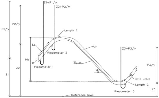
Figure 2.
Scheme of energy loss due to entrapped air.
The observed energy loss due to entrapped air was determined through the elevation difference between the beginning and end of air entrapped for a given flow rate (from 5 × 10⁻⁶ to 1.01 × 10⁻⁴ m3/s).
The calculated energy loss due to air was obtained by applying the energy equation using three piezometers [20]. The initial air body pressure was approximately at atmospheric conditions. Due to fact the air body boundaries were usually not at the location of piezometers 2 and 3, a unitary head friction loss was defined between piezometers 1 and 2 for a given flow rate. The unitary head friction loss was used to calculate the head friction loss in Lengths 1 and 2 (Figure 2); those lengths were measured using a flexible measuring tape. The effect of small air bubbles in Length 2 was neglected. Considering the head in piezometers 1, 2, and 3, the constant length between piezometers 1 and 2, the lengths between the air body boundaries regarding piezometers 2 and 3, and a reference level (Figure 2), the calculated energy loss was obtained using Equation (1):
where is the calculated energy loss due to entrapped air (m), is the piezometric head in piezometer 1 (m), is the piezometric head in piezometer 2 (m), is the piezometric head in piezometer 3 (m), is the constant length between piezometers 1 and 2 (m), is the Length 1 between piezometer 2 and the left air–body boundary (m), and is the Length 2 between piezometer 3 and the right air–body boundary (m).
2.3. Air Bubbles’ Removal Due to Hydraulic Jump Turbulence
The air bubbles’ removal due to the turbulence of a hydraulic jump located downstream of an air body in 15°, 30°, 45°, and 60° downward slope pipelines in 19.05, 25.4, and 31.75 mm of diameter were studied. In the 38.1 mm pipeline diameter, data related to the 15° and 30° downward slope were collected. The experiences of Kalinske and Robertson [21] and Escarameia [17] were considered to calculate the air flow removed by a hydraulic jump in a circular pipeline (𝑄𝑎). The previous authors stated that the phenomenon depends: to a greater extent on the water flow (𝑄𝑤), the hydraulic jump intensity defined by the Froude number of the minor conjugate (), and to a lesser extent on the pipeline inclination angle (θ). The dimensionless ratio (β) related to the air flow () concerning the water flow () was determined as a function of and (Equation (2)):
The water flow was measured using an ultrasonic meter. In contrast, the air flow was estimated by measuring the air volume change (through air length change) registered in a given time and constant water flow with a measuring tape. The Froude number of the hydraulic jump was estimated through the hydraulic characteristics of the circular channel associated with the pipeline. Measurements of average water velocity, cross-sectional area, and top width of the water surface were collected. The mathematical models proposed in this research were obtained from 10 flow measurements and their hydraulic characteristics for each downward slope and pipeline diameter. Mathematical models with potential relationships were adjusted and diagnosed.
2.4. Entrapped Air Removal Due to Hydrodynamic Thrust
The complete entrapped air removal due to the action of a hydrodynamic thrust during the filling process of a gravity-driven water pipeline was studied. The mathematical representation of the phenomenon was approached with the experiences of the investigations of Kalinske and Bliss [11], Kent [12], Gandenberger [13], Wisner et al. [14], Corcos [8], Escarameia [17], Pothof and Clemens [22], Pozos et al. [5], and May et al. [3].
The phenomenon was modeled with the Froude scale, which involves an air removal velocity (or critical) (), pipeline diameter (), and gravity acceleration (). This scale is known as the dimensionless air removal parameter, being a function of the pipeline’s downward slope () and, in some cases, air volume to be removed () (Equation (3)):
Water flow measurements were collected in which an air body of a given length (formed during the installation filling) was removed in downward slopes of 0°, 5°, 10°, 15°, 20°, 30°, 45°, and 60° and pipeline diameters of 12.7, 15.875, 19.05, 25.4., 31.75, and 38.1 mm. Ten water flow and entrapped air length measurements were collected in each downward slope and pipeline diameter. Using the average values of the dimensionless air removal parameter and the pipeline’s downward slope, linear mathematical models were adjusted and diagnosed.
In order to define the representativeness of the aforementioned obtained models, a diagnosis of the assumptions regarding the residual’s normality, homoscedasticity, and independence was made. In the case of the air bubbles’ removal models, the potential mathematical models were linearized using logarithms. In the case of the entrapped air removal due to hydrodynamic thrust models, a one-way ANOVA was utilized to demonstrate that the downward slope produced a statistically significant effect on the dimensionless air removal parameter (𝑉⁄√𝑔𝑑); and a Tukey’s test was elaborated to integrate different pipeline diameters within a model [23].
3. Results and Discussion
3.1. Energy Loss Generated by Entrapped Air
It was observed that the energy loss by entrapped air significantly impacts the optimal functioning of a water supply system. The energy potentially available in the system depends on the elevation of the pipeline upstream of the entrapped air. Due to entrapped air, the available energy of the system decreased, as well as the water transport capacity in the pipeline. When the energy loss generated by the air was equal to the available energy of the system, a complete blockage of the water flow was noticed.
The results of Table 1 pointed out that in 12.7, 15.875, 19.05, 25.4, 31.75, and 38.1 mm pipeline diameters, the energy loss caused by entrapped air approximates the air’s vertical height independently of the pipeline’s downward slope. The observed energy loss presented a difference of ±4% compared to the calculated energy loss. The latter difference is close to the one reported by May et al. [3] in the 25.4 and 38.1 mm diameters.

Table 1.
Energy loss observed and calculated generated by entrapped air.
3.2. Air Bubbles’ Removal Due to Hydraulic Jump Turbulence
It was observed that if the energy available in the system is sufficient, a downward slope pipeline with at least one entrapped air body operates as a channel. Due to the water flow, the formation of a hydraulic jump downstream of an air body was observed, which removed small air bubbles by generation and entrainment [14].
As can be seen in Figure 3, Figure 4, Figure 5 and Figure 6, the air-water flow ratio (β) regarding the Froude number presented potential relationships. Similar relationships were found by Kalinske and Robertson [21], Escarameia [17], and Mortensen [24]. It should be noted that the resulting potential models are focused on representing the first air removal stage in pressurized pipelines. Those models are only applicable in the reported air-water ratio intervals (for the pipeline diameter of 19.05 mm, water flows from 2.2 × 10⁻⁵ to 4 × 10⁻⁵ m3/s; for 25.4 mm from 2.9 × 10⁻⁵ to 6.6 × 10⁻⁵ m3/s; for 31.75 mm from 3.3 × 10⁻⁵ to 6.6 × 10⁻⁵ m3/s; for 38.1 mm from 4.4 × 10⁻⁵ to 8.4 × 10⁻⁵ m3/s). The authors mentioned the above to point out that the pipeline slope is a factor that influences, to a lesser degree, air bubbles’ generation and entrainment due to the hydraulic jump turbulence, resulting in a factor that they do not directly consider in their models.
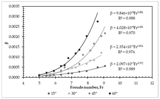
Figure 3.
Models of air bubbles removal in 19.05 mm pipeline diameter.
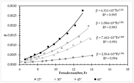
Figure 4.
Models of air bubbles’ removal in 25.4 mm pipeline diameter.

Figure 5.
Models of air bubbles’ removal in 31.75 mm pipeline diameter.

Figure 6.
Models of air bubbles’ removal in 38.1 mm pipeline diameter.
In the present study, it was observed that by increasing the pipeline’s downward slope degree, the air-water flow ratios (β) increased. In other words, greater air volume was removed under the same water flow.
Figure 3, Figure 4, Figure 5 and Figure 6 show the dimensionless relationships (β) obtained concerning the Froude number () in 15°, 30°, 45°, and 60° downward angles in 19.05 mm, 25.4 mm, 31.75 mm, and 38.1 mm pipeline diameters, respectively.
Due to the constant air bubbles’ removal out of the hydraulic jump turbulence, it was observed that if there is another air body downstream to the original air body, the air bubbles removed will join the subsequent air body. Additionally, it was detected that the removed air was evacuated from the installation only if there was no downstream profile that favored air bubbles’ accumulation and consequently created another air body, which is only removed with the removal velocity [8].
Moreover, it was observed that as the pipeline diameter increased, a greater water flow was required to cause air bubbles’ removal because the Froude number increased, and the water-air flow ratio decreased (Figure 7). Also, it was detected that in water flows higher than those reported in this study, the water and air flow varied rapidly because the available energy in the system increased and decreased due to the air bubbles’ removal and return to the hydraulic jump turbulent zone. Hence, the highest air-water flow ratio depicted the threshold towards transient flow in each downward slope.
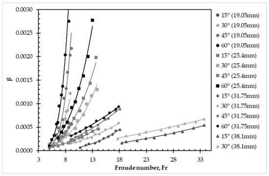
Figure 7.
Models overview of air bubbles’ removal in small diameter pipelines.
In the case of horizontal pipelines, air bubbles’ generation was not observed due to the turbulence of the hydraulic jump; this phenomenon occurred just in downward slope pipelines [8,25].
Mortensen et al. [24] indicated that air release is independent of the pipe size in diameters of 76.2, 177, 300, and 591 mm with a constant downward slope of 4% if the hydraulic jump is within the pipeline. However, the latter results are comprehensible since Zukoski [26] stated that viscosity and surface tension effects are minuscule in pipelines equal to or greater than 175 mm. At the same time, Pothof and Clemens [22] indicated that the critical velocity of moving an air body is not affected by surface tension in the pipeline’s diameters greater than 200 mm. Similarly, Baines and Wilkinson [27] described consistent results in rectangular ducts.
Unlike the models reported by Kalinske and Robertson [21], Escarameia [17], and Mortensen [24], in this study it was found that the downward angle is an important factor to consider in the configuration of mathematical models for air bubbles’ removal in small diameters (see θ in Figure 2). There is a dependency between air bubbles’ removal regarding the pipeline’s downward slope and the system’s diameter. The scale effects on air bubbles’ removal are relevant in small diameters, likely by viscosity and surface tension [22,26].
The comparative graph in Figure 8 shows the differences in the behavior of air bubble removal models in circular pipelines. It considers the proposed models by Kalinske and Robertson [21], Escarameia [17], and one obtained in this study, particularly for a downward slope of 60° in a 19.05 mm pipeline diameter. The model obtained by Mortensen et al. [24] greatly overestimates the models of Kalinske and Robertson [21], Escarameia [17], and those developed in this research; for that reason, it is not included in Figure 8.
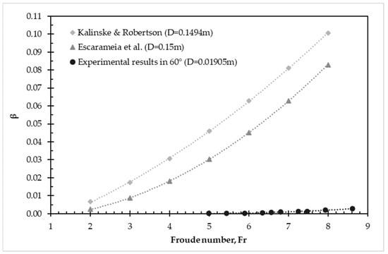
Figure 8.
Comparison of a model obtained with respect to proposed models in air bubbles’ removal due to a hydraulic jump [17,21].
It is observed that the models of Kalinske and Robertson [21] and Escarameia [17] have a similar potential trend regarding one of the models defined in this study. However, the differences among those relationships can be explained due to the mentioned models which were developed in different scales compared to the ones obtained in the present research. Since the potential relation of 19.05 mm pipeline diameter is located under Kalinske and Robertson [21] and Escarameia’s [17] models (Figure 8), the remaining models obtained (regarding 25.4, 31.75, and 38.1 mm) are under the aforementioned models.
3.3. Entrapped Air Removal Due to Hydrodynamic Thrust
The results of entrapped air removal due to the effect of a hydrodynamic thrust are summarized in Table 2, related to 12.7, 15.875, 19.05, 25.4, 31.75, and 38.1 mm pipeline diameters and downward slopes of 0°, 5°, 10°, 15°, 20°, 30°, 45°, and 60°.
Table 2.
Averages of the dimensionless air removal parameter in the entrapped air removal due to a hydrodynamic thrust.
It was found that the dimensionless air removal parameter (𝑉⁄√𝑔𝑑) is closely linked to the pipeline’s downward slope. The greater the downward angle, the greater the removal velocity required to remove entrapped air bodies by the hydrodynamic thrust action. The similarity in the average values of the dimensionless air removal parameter was observed for 12.7, 15.875, and 19.05 mm and 25.4, 31.75, and 38.1 mm pipeline diameters (Table 2).
The results of the one-way analysis of variance indicated that the downward slope produces a statistically significant effect on the dimensionless air removal parameter (Table 3).
Table 3.
One-way analysis of variance (α = 0.05).
Moreover, Tukey’s test corroborated the similarity in the average dimensionless air removal parameter values between diameter group 1 (12.7, 15.875, and 19.05 mm) and 2 (25.4, 31.75, and 38.1 mm) (Table 4). Consequently, the behaviors of these groups were represented with independent linear mathematical models (Figure 9).
Table 4.
Tukey’s test (α = 0.05).
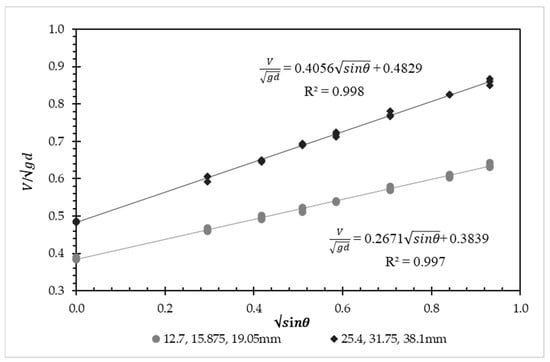
Figure 9.
Models’ overview of entrapped air removal due to a hydrodynamic thrust in small pipeline diameters.
On the one hand, Gandenberger [13] and Escarameia [17] considered the air volume to be removed as a parameter to obtain the dimensionless air removal parameter. On the other hand, May et al. [3] pointed out that the air removal velocity is independent of the air body length; consequently, entrapped air volume was not considered in their models. In the present study, low variation in the removal water flow was observed regarding the air pockets length; therefore, the air volume removed was not integrated into the obtained mathematical models.
It should be noted that the air removal phenomenon due to the hydrodynamic thrust action was found in transient flow conditions, so the removal flow occurs in a short time interval. It was observed that as the pipeline’s downward angle was higher, the air removal was more turbulent, generating overpressures and vibrations on the conduction line. The aforementioned overpressures were not measured.
Two mathematical models were adjusted and diagnosed to represent the dimensionless air removal parameter as a function of the square root of the sine downward angle. Using these models, it is possible to determine the required water velocity to remove entrapped air bodies in small pipeline diameters (formed while filling) by the hydrodynamic thrust action in downward angles between 0° and 60°. The models’ experimental components consider the surface tension and water viscosity effects indirectly.
Finally, Figure 10 shows a graph summarizing several mathematical models proposed in the specialized literature and two found in this study for diameter groups 1 and 2 (gray and black solid lines). Most air removal models are calibrated for pipelines with diameters greater than 0.0762 m, which are not applicable for smaller pipeline diameters. The smallest diameter reported corresponds to 0.0254 m [3]. The large spread in the reported correlations is partially produced by scale effects as reported in Pothof and Clemens [28]. It is observed that the models obtained in this study are in the same range as the previously developed models.
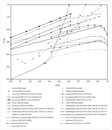
Figure 10.
Comparison of the air removal models obtained with respect to models proposed in the literature [3,5,8,10,11,12,13,14,15,16,17,25,29,30,31].
Regarding the model’s diagnosis, both air bubbles’ removal due to hydraulic jump turbulence and entrapped air removal due to hydrodynamic thrust models have good representativeness of the studied phenomena since the correlation coefficients (R2) are equal to or greater than 0.97. Also, the model’s residuals are normally distributed, present constant variance (homoscedasticity), and independent. Focusing only on small diameters reduces the models’ uncertainty.
4. Conclusions
It was corroborated that the energy loss caused by an air body is approximately equivalent to its height by applying the energy equation between the air body at the beginning and end in 12.7, 15.875, 19.05, 25.4, 31.75, and 38.1 mm pipeline diameters, presenting differences of approximately ±4%.
It was found that the air bubbles’ removal due to the hydraulic jump turbulence is sensitive to the pipeline’s downward angle. Models were determined for each downward angle and diameter. Due to scale issues (small pipeline diameters), the defined models were below those reported in the literature.
The water velocity at which air bodies were removed by the hydrodynamic thrust action in downward slopes was identified. The linear mathematical models integrated the water velocity’s removal into the dimensionless air removal parameter.
Two linear mathematical models were obtained for air removal by the hydrodynamic thrust action in downward angles from 0° to 60°. One represents 12.7, 15.875, and 19.05 mm diameters, and the other 25.4, 31.75, and 38.1 mm.
This study extends and complements the existing ones since small diameters were analyzed, lower than those generally reported in the specialized literature.
Author Contributions
Conceptualization, E.Q.-M., J.V.P.-H., J.M.-V. and J.R.Q.-M.; methodology, E.Q.-M., J.V.P.-H. and J.M.-V.; validation, E.Q.-M. and J.V.P.-H.; formal analysis, E.Q.-M., J.V.P.-H. and J.M.-V.; investigation, E.Q.-M., J.V.P.-H. and J.M.-V.; resources, E.Q.-M. and J.V.P.-H.; writing—original draft preparation, E.Q.-M., J.V.P.-H. and J.M.-V.; writing—review and editing, E.Q.-M., J.V.P.-H., J.M.-V. and J.R.Q.-M.; supervision, E.Q.-M. and J.V.P.-H. All authors have read and agreed to the published version of the manuscript.
Funding
This research was funded by the Chapingo Autonomous University (UACh).
Data Availability Statement
Data of this study are available upon request to the corresponding author.
Acknowledgments
The authors are grateful for the University of Lleida’s support at the beginning of this research project.
Conflicts of Interest
The authors declare no conflict of interest.
Appendix A

Figure A1.
Experimental setup.
Figure A1.
Experimental setup.

References
- Ramezani, L.; Karney, B.; Malekpour, A. Encouraging effective air management in water pipelines: A critical review. J. Water Resour. Plan. Manag. 2016, 142, 04016055. [Google Scholar] [CrossRef]
- Stephenson, D. Effects of air valves and pipework on water hammer pressures. J. Transp. Eng. 1997, 123, 101–106. [Google Scholar] [CrossRef]
- May, D.; Allen, J.; Nelson, D. Hydraulic investigation of air in small diameter pipes. Int. J. Hydraul. Eng. 2018, 7, 51–57. Available online: http://article.sapub.org/10.5923.j.ijhe.20180703.02.html (accessed on 10 October 2022).
- Dean, J.A. Lange’s Handbook of Chemistry; McGraw-Hill, Inc.: New York, NY, USA, 1999. [Google Scholar]
- Pozos, O.; Gonzalez, C.A.; Giesecke, J.; Marx, W.; Rodal, E.A. Air entrapped in gravity pipeline systems. J. Hydraul. Res. 2010, 48, 338–347. [Google Scholar] [CrossRef]
- Colgate, D. Hydraulic Model Studies of the Flow Characteristics and Air Entrainment in the Check Towers of the Main Aqueduct, Canadian River Project Texas; Report Hyd-555; U.S. Dept. of the Bureau of Reclamation: Denver, CO, USA, 1966.
- Ochoa, L.H. Modelación de aire atrapado en flujo de agua en conductos (Modeling Entrapped Air in Water Flow in Pipelines). Ph.D. Thesis, National Autonomous University of Mexico, Mexico City, Mexico, 2005. [Google Scholar]
- Corcos, G. Air in Water Pipes: A Manual for Designers of Spring Supplied Gravity-Driven Drinking Water Rural Delivery Systems, 2nd ed.; Agua Para La Vida: Berkeley, CA, USA, 2003. [Google Scholar]
- Fuertes-Miquel, V.S.; Coronado-Hernández, O.E.; Mora-Meliá, D.; Iglesias-Rey, P.L. Hydraulic modeling during filling and emptying processes in pressurized pipelines: A literature review. Urban Water J. 2019, 16, 299–311. [Google Scholar] [CrossRef]
- Liou, C.P.; Hunt, W.A. Filling of pipelines with undulating elevation profiles. J. Hydraul. Eng. 1996, 122, 534–539. [Google Scholar] [CrossRef]
- Kalinske, A.A.; Bliss, P.H. Removal of air from pipelines by flowing water. Am. Soc. Civ. Eng. 1943, 13, 480–482. [Google Scholar]
- Kent, J.C. The Entrainment of Air by Water Flowing in Circular Conduits with Downgrade Slopes. Ph.D. Thesis, University of California, Berkeley, CA, USA, 1952. [Google Scholar]
- Gandenberger, W. Über die wirtschaftliche und betriebssichere Gestaltung von Fernwasserleitungen (Design of Overland Water Supply Pipelines for Economy and Operational Reliability); R. Oldenbourg: Munich, Germany, 1957. [Google Scholar]
- Wisner, P.E.; Mohsen, F.N.; Kouwen, N. Removal of air from water lines by hydraulic means. J. Hydraul. Div. ACSE 1975, 101, 243–257. [Google Scholar] [CrossRef]
- Falvey, H.T. Air-Water Flow in Hydraulic Structures; Engineering Monograph 41; United States Department of the Interior, Bureau of Reclamation: Denver, CO, USA, 1980.
- Walski, T.M.; Barnhart, T.S.; Driscoll, J.M.; Yencha, R.M. Hydraulics of corrosive gas pockets in force mains. Water Environ. Res. 1994, 66, 772–778. [Google Scholar] [CrossRef]
- Escarameia, M. Investigating hydraulic removal of air from water pipelines. Proc. Inst. Civ. Eng. Water Manag. 2007, 160, 25–34. [Google Scholar] [CrossRef]
- Lauchlan, C.S.; Escarameia, M.; May, R.W.P.; Burrows, R.; Gahan, C. Air in Pipelines: A Literature Review; Report SR 649; HR Wallingford: Oxfordshire, UK, 2005. [Google Scholar]
- Lima-Neto, I.E.; de Melo-Porto, R. Performance of low-cost ejectors. J. Irrig. Drain. Eng. 2004, 130, 122–128. [Google Scholar] [CrossRef]
- Lindell, J.E.; Moore, W.P.; King, H.W. Handbook of Hydraulics, 8th ed.; McGraw-Hill Education: New York, NY, USA, 2017. [Google Scholar]
- Kalinske, A.A.; Robertson, J.M. Closed Conduit Flow. Trans. Am. Soc. Civ. Eng. 1943, 108, 1435–1447. [Google Scholar] [CrossRef]
- Pothof, I.; Clemens, F. On elongated air pockets in downward sloping pipes. J. Hydraul. Res. 2010, 48, 499–503. [Google Scholar] [CrossRef]
- Montgomery, D.C. Design and Analysis of Experiments, 8th ed.; John Wiley & Sons: Hoboken, NJ, USA, 2013. [Google Scholar]
- Mortensen, J.D.; Barfuss, S.L.; Johnson, M.C. Scale effects of air entrained by hydraulic jumps within closed conduits. J. Hydraul. Res. 2011, 49, 90–95. [Google Scholar] [CrossRef]
- Benjamin, T.B. Gravity currents and related phenomena. J. Fluid Mech. 1968, 31, 209–248. [Google Scholar] [CrossRef]
- Zukoski, E. Influence of viscosity, surface tension and inclination on motion of long bubbles in closed tubes. J. Fluid Mech. 1966, 25, 821–837. [Google Scholar] [CrossRef]
- Baines, W.D.; Wilkinson, D.L. The motion of large air bubbles in ducts of moderate slope. J. Hydraul. Res. 1986, 25, 157–170. [Google Scholar] [CrossRef]
- Pothof, I.W.M.; Clemens, F.H.L.R. Experimental study of air-water flow in downward sloping pipes. Int. J. Multiph. Flow 2011, 37, 278–292. [Google Scholar] [CrossRef]
- Mosvell, G. Luft i Utslippsledninger (Air at Outfalls); Project Committee on Sewage, PRA Report 8; Norwegian Water Institute: Oslo, Norway, 1976. [Google Scholar]
- Townson, J.M. Free-Surface Hydraulics; Unwin Hyman: London, UK, 1991. [Google Scholar]
- Veronese, A. Sul Motto delle Bolle D’aria nelle Condotte D’acqua (On the Motto of Air Bubbles in the Water Pipeline); Estrato dal Fasciacolo X: Roma, Italy, 1937; Volume XIV, p. XV. [Google Scholar]


Disclaimer/Publisher’s Note: The statements, opinions and data contained in all publications are solely those of the individual author(s) and contributor(s) and not of MDPI and/or the editor(s). MDPI and/or the editor(s) disclaim responsibility for any injury to people or property resulting from any ideas, methods, instructions or products referred to in the content. |
© 2023 by the authors. Licensee MDPI, Basel, Switzerland. This article is an open access article distributed under the terms and conditions of the Creative Commons Attribution (CC BY) license (https://creativecommons.org/licenses/by/4.0/).