Article

Bridge Pier Scour in Complex Environments: The Case of Chacao Channel in Chile

by
Francisco Martinez
1,*,†,
Patricio Winckler
2,3,4,†,
Luis Zamorano
5,† and
Fernando Landeta
6,†
1
School of Civil Engineering, Pontificia Universidad Catolica de Valparaiso (PUCV), Valparaiso 2340000, CP, Chile
2
Escuela de Ingenieria Civil Océanica, Universidad de Valparaíso (UV), Valparaiso 2362844, CP, Chile
3
National Research Center for Integrated Natural Disaster Management (CIGIDEN), Vicuña Mackenna 4860, Macul 7820436, Chile
4
Centro de Observación Marino para Estudios de Riesgos del Ambiente Costero (COSTAR), Valparaiso 2362844, CP, Chile
5
Instituto Nacional de Hidráulica (INH), Santiago 8320000, CP, Chile
6
Skyring Marine Ltda., Valparaiso 2340000, CP, Chile
*
Author to whom correspondence should be addressed.
These authors contributed equally to this work.
Water 2023, 15(2), 296; https://doi.org/10.3390/w15020296
Submission received: 30 November 2022 / Revised: 30 December 2022 / Accepted: 31 December 2022 / Published: 11 January 2023
(This article belongs to the Special Issue Sediment Transport at Bridges and River Training Structures)

Abstract

:
Chacao channel bridge is located in a tidal channel with highly-energetic hydrodynamics conditions and significant erodibility potential. Once finished, this 2.5 km long cable-stayed bridge will be the largest in South-America. Here we report an integrated procedure to estimate scour around two of its three towers, both located on a relatively complex but different soil matrices. A high-resolution hydrodynamic model based on the Reynolds-averaged Navier–Stokes equations (RANS), physical tests of in situ soil samples in a Rotating Erosion Testing Apparatus (RETA) and empirical formulas for scour estimation are combined to provide a reliable estimation of scour depth under a periodic tidal ebb-flow regime. The relatively homogeneous soil material at the North Tower shows a high susceptibility to hydrodynamic erosion, which is estimated with SRICOS methodology. The Central Tower, in contrast, needs a combined approach based on the current state of the rock, information collected from underwater explorations and theoretical progress made about rock scour in order to reduce the uncertainty of the soils’ substrate. This study reveals that scour estimation for engineering design purposes in complex soils can be achieved with a joined vision of different disciplines and modelling tools for minimizing the uncertainty.

1. Introduction

Chacao Channel bridge is one of the most important civil works built in recent decades in Chile and, once in operation, will be the longest cable-stayed bridge in South-America [1,2,3]. Once the concession contract expires, the bridge will be managed by the Ministry of Public Works [4]. The 2.5 km long bridge will span between continental Chile and Chiloé Island (Figure 1a), sites which are currently connected by a system of ferries along a highly energetic tidal channel (Figure 1b). Travel times will be reduced in nearly 27 min once the bridge is in operation and the connection with the island will be guaranteed during storms, which currently cause operational downtime of ferries. The bridge (Figure 1c) consists of four traffic lanes and will cross a channel of up to 100 m deep. At its narrowest 2.2 km wide section, Chacao Channel exhibits an isolated pinnacle, Remolinos Rock (Figure 1d), which separates the stream in two smaller waterways [5] and where maximum speeds may reach about 6 m/s during spring tides. Remolinos Rock provides a shallow basis for its Central Tower (CT), currently under construction (Figure 1e) [6]. The North Tower (NT), conversely, will be located in a shallow base near the northern coast (Figure 1f). The design life of the structure is T = 100 years [1].
The hydrodynamics of the nearly 26 km long Chacao Channel, which connects the Pacific Ocean with the Chilean Inland Sea (Figure 1a), is strongly dominated by differences in tide levels and phases between its two ends. At its easternmost side, the channel flows into a complex system of channels extending from 41° S to 47° S, which in turn is divided in two main water bodies with different yet correlated tidal patterns located north and south of the Guafo Mouth [7]. The northern extreme of the Chilean Inland Sea is characterized by a strong amplification of the semidiurnal tidal constituents, explained by resonant effects of tides entering through Guafo Mouth [5,7]. As a consequence of this amplification, tidal ranges of up to 7 m are observed in Puerto Montt during spring tides, largely exceeding the 2 m range found in the open ocean.
Simulating currents in Chacao Channel is a challenging task, mainly because the hydrodynamic system is fairly complex. Tides are the most important driving force within the channel, when contrasted to meteorological effects and river discharges [8]. Several measurements performed in Chacao Channel, e.g., ICUATRO-COWI [6], and tide levels from the national tide gauge network have been used to calibrate hydrodynamic models within the Chilean Inland Sea [9,10,11,12], in which tides were prescribed as boundary conditions in relatively small domains. Winckler et al. [13] improved the modelling approach by using a much larger domain where the tidal potential of the main constituents was used in both the momentum equations and boundary conditions far from the continental shelf. The boundary conditions of the high-resolution hydrodynamic models used in the present study for the CT and NT are based on such model.
Environmental conditions in the site are particularly difficult including, aside from the high currents mentioned above, a complex soil structure and high seismicity. These conditions have prompted the introduction of innovative engineering methodologies or adaptation of existing ones in order to reduce the uncertainty in the project [2,3,6,14]. Still, significant gaps remain in design conditions, particularly those related to the long-term fluid structure interaction and the estimation of scour [15,16]. To this concern, design guidelines to estimate scour are readily available in non-cohesive granular soils [17,18,19,20], but they are scarce and subject to large uncertainty in cohesive, cementated or rocky materials [21,22,23,24,25,26,27].
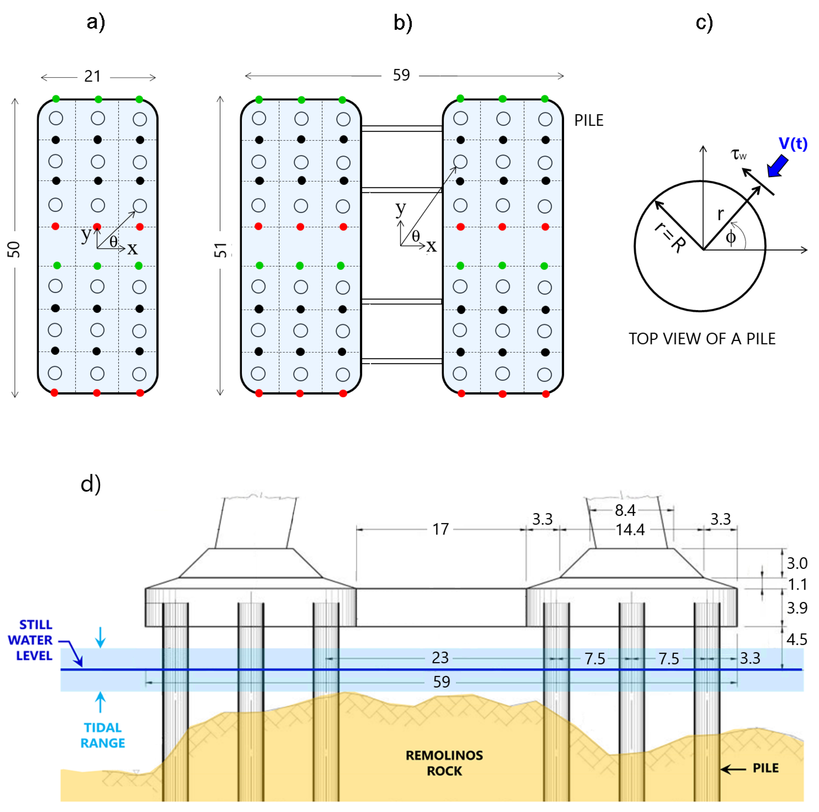
This study deals with the scour estimation of the soil substrates supporting the NT and CT of the bridge, which geometry is shown in Figure 2. Both structures are located within a hydrodynamically complex zone, dominated by intense bidirectional tidal currents which will persistently act during the lifetime of the project. Soil conditions are particularly complex as well: While NT’s substrate is formed by highly cohesive materials, CT’s substrate in Remolinos Rock has a very heterogeneous lithological composition, whose origin is not well known [1]. This rock shows some faces offering little to null erodibility, whereas others can be eroded by simply touching them [28]. These characteristics introduce high uncertainties in the estimation of scour depth, thus forcing designers to adapt already existing methods. This study, supported in a close public-private collaboration, discusses the strengths, limitations and uncertainties of the methods used in the design, together with the complex environmental conditions judged atypical for this kind of studies.

2. Methodology

2.1. Modelling Flow Fields

The numerical simulation of the flow, particularly in the vicinity the bridge, was calculated with OpenFoam [30], which solves the Reynolds-Averaged Navier-Stokes equations [31]:
ρ u i t + ( u i u j ) x j = P x i + ( μ + ρ ν t ) 2 u i x i 2 + ρ g i
u i x i = 0
where i , j = 1 , 2 , 3 and u i are the components of the velocity field in rectangular coordinates denoted by x j , P the hydrodynamic pressure, g i the components of gravity ( g 1 = g 2 = 0 ; g 3 = 9.8 ms−2), ν the fluid viscosity (= 10 6 m2s−1) and ν t the turbulent viscosity. This last parameter is a function of the turbulent kinetic energy of the flow k and the and turbulence specific dissipation rate ω [31] both of which are estimated from the k ω SST turbulence closure model of an incompressible flow [30,31,32,33]:
k t + ( u ¯ j k ) x j = τ i j ρ u ¯ j x j β * ω k + x j ( ν + σ k ν t ) k x j
ω t + ( u ¯ j ω ) x j = γ ν t τ i j ρ u ¯ j x j β ω 2 + x j ( ν + σ k ν t ) ω x j + 2 ( 1 F 1 ) σ ω 2 ω k x j ω x j .
where u ¯ j denote the time-averaged components of the velocity field u j . Flow shear stress can be calculated from the relationship:
τ i j ρ = ν t u ¯ i x j + u ¯ j x i 2 3 k δ i j ,
with δ i j the Kronecker delta function. The rest of the parameters are constants of the model. The turbulent kinematic viscosity is estimated as:
ν t = α 1 k max ( α 1 ω , Ω F 2 )
where α 1 = 0.31 , Ω = 2 w i j w i j , with w i j are the components of the vorticity vector w and F 2 = tanh ( λ 2 ) , with:
λ = max ( 2 k d β * ω , 500 ν ω d 2 )
where d is the distance from the field point to the nearest wall. With these elements, the following model parameters were adopted:
β * = 0.09 β 1 = 0.075 β 2 = 0.083 γ 1 = 0.553 γ 2 = 0.44 σ k 1 = 0.85 σ k 2 = 1.00 σ ω 1 = 0.50 σ ω 2 = 0.856
With this choice, the parameters σ k , σ ω , γ , β , F 1 , F 2 involved in Equations (3)–(7), were easily estimated [32,33].
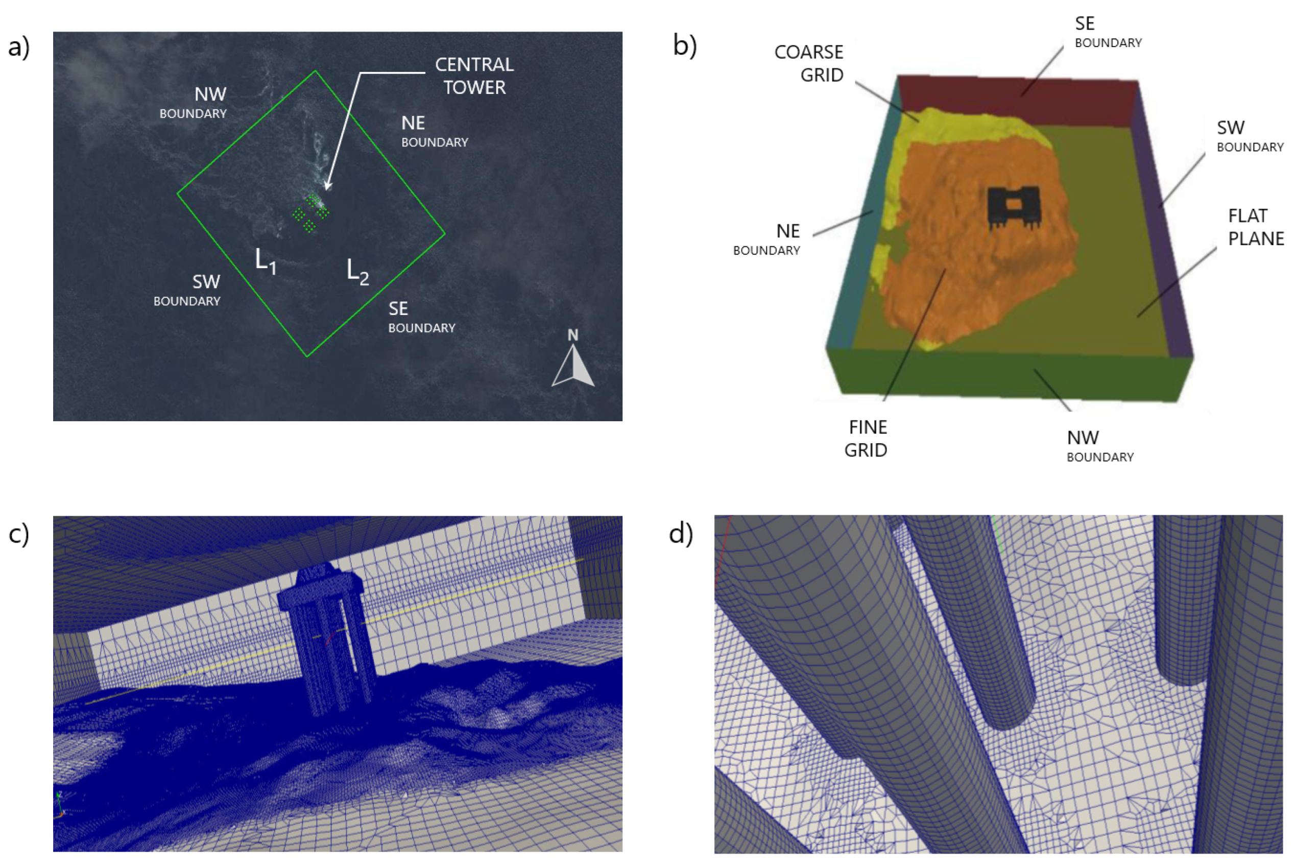
Modeling domains for the CT and NT were defined in rectangles of L 1 × L 2 = 1150 × 1050 m2 and 1150 × 950 m2, respectively (Figure 3a). The boundaries and bathymetric regions of each domain were differentiated by mesh refinement levels (Figure 3b). Far from the towers, the seafloor and the mean sea level, the cell-size was set to 8 m in all directions. The grid was progressively refined toward the structures to properly include the bathymetric characteristics of the seafloor (Figure 3c). The grid adopted a cylindrical shape with a radius of 60 m just above the center of mass of CT and NT, with a cell-size of 2 m. Piles and its surroundings upto 1 m were modelled with cell-sizes of 0.25 m (Figure 3d). A cell-size of 2 m was also used within a band of 5 m centered vertically at the mean sea level. The choice of the grid and the cells size refinement, particularly near the walls of the numerical domain, was based on the own experience of designers fitting the critical deadlines of the project. Other CFD parameters adopted for these simulations are included in Table 1. Each simulation took around 12 to 18 h with nearly 120 parallel processors. These computations lead to simulation periods Δ T of around 370 s (≈6.2 min) up to 550 s (≈9.2 min), which were enough to observe a completely developed flow around the piles of each tower. The steady regime was reached once no significant variation of the hydraulic parameters of incoming flow (e.g., water depth, velocity) were observed. This usually occurred at the time t * < Δ T , varying between 350 s and 530 s. Once the steady regime was reached, a periodic vortex shedding phenomena was generated downstream each row of piles. The analysis of the most significant hydraulic variables of the flow (e.g., shear stress and velocity components) was undertaken considering this phenomenon into the steady regime (i.e., for t [ t * , Δ T ] ).
Flow velocities u j and flow shear stresses τ i j around the structure were obtained from the software ParaView [34]. These fields were calculated for a flood-tide and an ebb-tide scenarios. Velocity and flow depth at NW and SE boundaries of our high resolution models (Figure 3b) were obtained from a large-scale model built in a Mike21, using the non-linear shallow water equations for extreme tidal ranges [13]. Table 2 defines the boundary conditions at both sites. The large-scale model was calibrated using four tide gauges, one ADCP and two current meters along Chacao Channel, and then validated with three tide gauges and an ADCP at different sites. The model-to-data comparisons of the large-scale model showed coefficients of determination of R 2 = 96 % for tide elevations and R 2 = 73 % for depth-averaged speeds at the study site, values which are considered acceptable given the complex hydrodynamic patterns of Chacao Channel. Finally, the boundary conditions of the closure turbulence equations were imposed constant over time and estimated based on the freestream velocity, a turbulence intensity equal to 10%, and a turbulence length scale equivalent to 7% of the depth; typical values used when measurements are not available [35].

2.2. Estimation of the Erosion Rate in Earth Materials

To determine the erosion rate, we conducted experimental tests with the Rotational Erosion Test Apparatus (RETA), a device that measures the rate of erosion of different earth materials induced by the application of a shear stress at sample’s surface [36,37,38]. Five samples were obtained for NT and CT, however, only three were used for the former while no samples at CT were discarded. Figure 4d,e show the state of some samples obtained at both sites sites after tests.
The RETA measures the mass loss of the sample within a given period and a range of shear stresses [38]. Its configuration follows a Couette-like geometry, with a cylindrical sample in the center and an outer cylinder rotating at a constant speed ω , which mobilizes the water in between (Figure 4a). Before each test, the samples are trimmed, smoothed and perforated in the center, generating a cylindrical volume (Figure 4b). The dimensions and saturated mass of the sample are measured before immersion. An initial spin lasting up to 12 h, guarantees the elimination of loose particles, thus avoiding unusual high erosion rates. After that, the sample is removed and the water drained (Figure 4c). The dimensions and saturated mass are recorded again, from which its surface area, density, and volume are estimated. In the actual test, the sample is placed in a slightly larger unit filled with water, where an initial torque is applied during an interval that depends on the scour resistance of the sample. Erosion can be determined visually by a trained operator in tests that can last up to 72 h.
After testing, eroded sediment is placed in an oven where water is evaporated. The mass of dry sediment corresponds to the eroded material. The average shear stress τ ( ω ) is estimated from:
τ ( ω ) = T ( ω ) 2 π R 2 L
where ω is the rotation speed of the cylinder, T the applied torque, R the radius and L the length of the sample. The erosion rate r ˙ , measured in mm·s−1, is estimated as:
r ˙ = Δ r Δ t Δ m 2 π ρ R D L
where Δ r is the average change of the sample radius for each test. This change is calculated assuming that all mass loss Δ m occurs uniformly across the outer surface of the sample within the interval Δ t . The parameter D = 2 R denotes the initial diameter of the sample and ρ the dry mass density. To account for the variability of the process, between 3 to 5 tests are performed for each sample. The repeatability of these tests is ensured by operating several RETA units in parallel using the same material.

2.3. Erosion and Scour in Central Tower

Soil at CT site is a complex rock material, for which many of existing scour formulas are not directly applicable. In general, determining erodibility and local scour in rocky materials is a difficult task for hydraulic engineering [21,24,25]. Erodibility of these materials has been studied to determine bedrock scour depth in dams due to the impact of a high power jet [39,40,41,42], to study the stability of spillway channels [43,44,45] and to determine the power required for excavating earth materials by means of an erosion index [46,47]. These findings have been extrapolated to flows around bridges [27], since most of existing methods were thought for non-cohesive granular materials, in which the resistance to erosion of clays, rocks and cemented materials is neglected. According to Arneson et al. [48], two modes of scour and erosion in rock could arise: The first mode, referred to as quarrying and plucking, involves the removal of relatively intact rock blocks in fissured and jointed rock masses. The second mode, more gradual, is caused by bedload abrasion of the rock surface over relatively long periods of time. Here we assumed the first mode is dominant in CT while the second mode is relevant in NT.
Scour prediction at Remolinos rock (CT) was based on the Erodibility Index Method (EIM) [21,22], taking into account its variable geological composition. This method considers the different mechanism involved in rock scour (Figure 5a–c), defining an erosion threshold for the soil when subjected to an erosive current of power P A and introducing a geomechanical dimensionless index known as erodibility index K. According to Keaton et al. [27], scour in rock is essentially controlled by rock type, discontinuity spacing, abrasion resistance and weathering rate. For example, fractured and weathered rocks are more susceptible to scour, while mechanical and chemical weathering can also increase the susceptibility. Then, K quantifies the relative ability of the material to resist erosion. According to Annandale [22], K is defined as:
K = M s K b K d J s
where M s is the mass strength number, K b the block or particle size number, K d the discontinuity shear strength number, and J s the relative ground structure number, all of them dimensionless. M s and J s are estimated based on hardness and consistency of the material. In particular, M s is calculated as follows:
M s = 0.78 C r σ u c s 1.05 , if σ u c s 10 M P a C r σ u c s , if σ u c s > 10 M P a
where C r = ρ r g / 27 , 000 , ρ r is the density of the rock, and σ u c s is the unconfined compressive strength of the sample. This strength typically falls into the range 1.7 σ u c s 212 MPa [24]. The parameters K b and K d are calculated as follows:
K b = R Q D J n , K d = J r J a
where R Q D is the Rock Quality Designation, a standard dimensionless parameter in drill core logging [49], and J n is the joint set number, a dimensionless function of the number of joint sets in a rock mass (Figure 5d,e). A joint set is a family of parallel, evenly spaced joints that can be identified through mapping and analysis of their orientations, spacing, and physical properties [50]. When there is not much information about the bed, the parameter R Q D can theoretically be estimated as R Q D = 115 3.3 J c , where J c = 3 / δ + 3 and δ is the average diameter of rock blocks that are likely to detach from their matrix, measured in m. In turn, δ can be estimated as δ = ( J x J y J z ) 0.33 , an expression valid for δ > 0.1 m, where J x , J y , J z represent the mean spacing between contiguous cracks in the rock mass along ( x , y , z ) directions [24], all of them measured in m. R Q D index usually falls in the range 5 < R Q D < 100, where 5 and 100 represent rocks of very poor and very good quality, respectively. The index J n falls in the range 1 < J n < 5. The dimensionless parameters J r and J a denote the joint roughness number and joint alteration number, respectively, and can be obtained from [51].
The parameter K d typically varies in the range 1 < K d < 100 and thus, the erodibility index K varies from 1 to 100 for rocky beds. According to Yang [52], the available erosive stream power can be written as P A = γ q S f , where γ = ρ g is the specific weight, Q the flow rate, q = Q / W the flow rate per unit width, W the width of the channel, the length of the channel in the streamwise direction and s f the friction slope. This last parameter can be calculated as S f = d E / d x Δ E / , where Δ E is the energy dissipation. The available stream power P A can be written as [48]:
P A = γ q Δ E = τ V
where τ = γ R h S f is the shear stress acting on the rocky bed [53], R h is the hydraulic radius and V the mean flow’s velocity. Here τ and V are representative scales for velocity and shear stress, so that they can be chosen according to the purpose of the study. For a wide channel, the hydraulic radius satisfies R h h , where h is the mean flow’s depth for a given cross-section. Annandale [25] provided an alternative expression of Equation (12), as a function of the shear stress acting in the vicinity of the bedrock. According to this author, it is reasonable to assume that K is a function of the erosive power of the stream P = f ( K ) , traducing into a threshold diagram of erosion represented by the formula:
P = α K β
where the fitting parameters are α = 0.48 and β = 0.44 for K < 0.1 , and α = 1.0 and β = 0.75 for K > 0.1 [21,22]. Consequently if, for a given erosion index K, the available power P A is such that P < P A , there is erosion risk for the material, otherwise not [22]. If P A / P < 1 then Z = 0 , where Z is the scour depth. However, if P A / P > 1, the scour depth can be estimated from the relation [48]:
P P A = a ^ exp b ^ Z m a x B
where Z m a x is the expected maximum scour depth, ( a ^ , b ^ ) = ( 8.42 , 0.712 ) are fitting parameters and B = D is the width of the pile. Annandale [25] proposes a similar formula but with another values of ( a ^ , b ^ ) , although with significant scattering, revealing a non-unique definition of the scour depth in rocky materials.

2.4. Erosion and Scour at North Tower Site

Soil at NT site is constituted by a cohesive cemented soil, highly resistant to hydrodynamic erosion but not quite enough to be considered non-erodible. For this site, an easy way to relate the erosion rate r ˙ to the probable scour depth Z ( t ) is through the expression Z ( t ) = r ˙ t , leading to a maximum scour depth ( Z s ) m a x = r ˙ T , T being bridge’s lifetime. This formula assumes, however, that flow conditions are stationary, leading to unrealistic values of scour depth. A more realistic calculation should take into account the soil’s nature, varying hydrodynamic conditions and the asymptotic nature of the erosive process [54,55]. For such purposes, the SRICOS-EFA method (Scour Rate In COhesive Soil – Erosion Function Apparatus) proposed for bridges by Briaud [56,57,58,59] was used herein. This method has been applied to estimate scour at bridge piers [60,61], in contraction zones [62] or a combination of both, including piers of different cross-sections, with different angles of attack and pier spacing [62]. This leads to scour evolution curves Z ( t ) for a variable velocity V ( t ) , and can be applied to cohesive, non-cohesive, stratified and uniform granular materials, silts, clays and some soft rocks characterized by a threshold shear stress τ c [63,64]. According to Briaud [63] once the flow-induced shear stress exceeds τ c , the material erodes following the evolution curve:
Z ( t ) = t r ˙ + t Z m a x 1
where Z m a x = 0.18 ( R e ) 0.635 is a parameter, R e = V h / ν is the Reynolds number of the upstream flow, V = Q / W h is the mean flow velocity, h is the mean flow depth, and t is the time such that 0 t T .

3. Results for North Tower

3.1. Flow Field

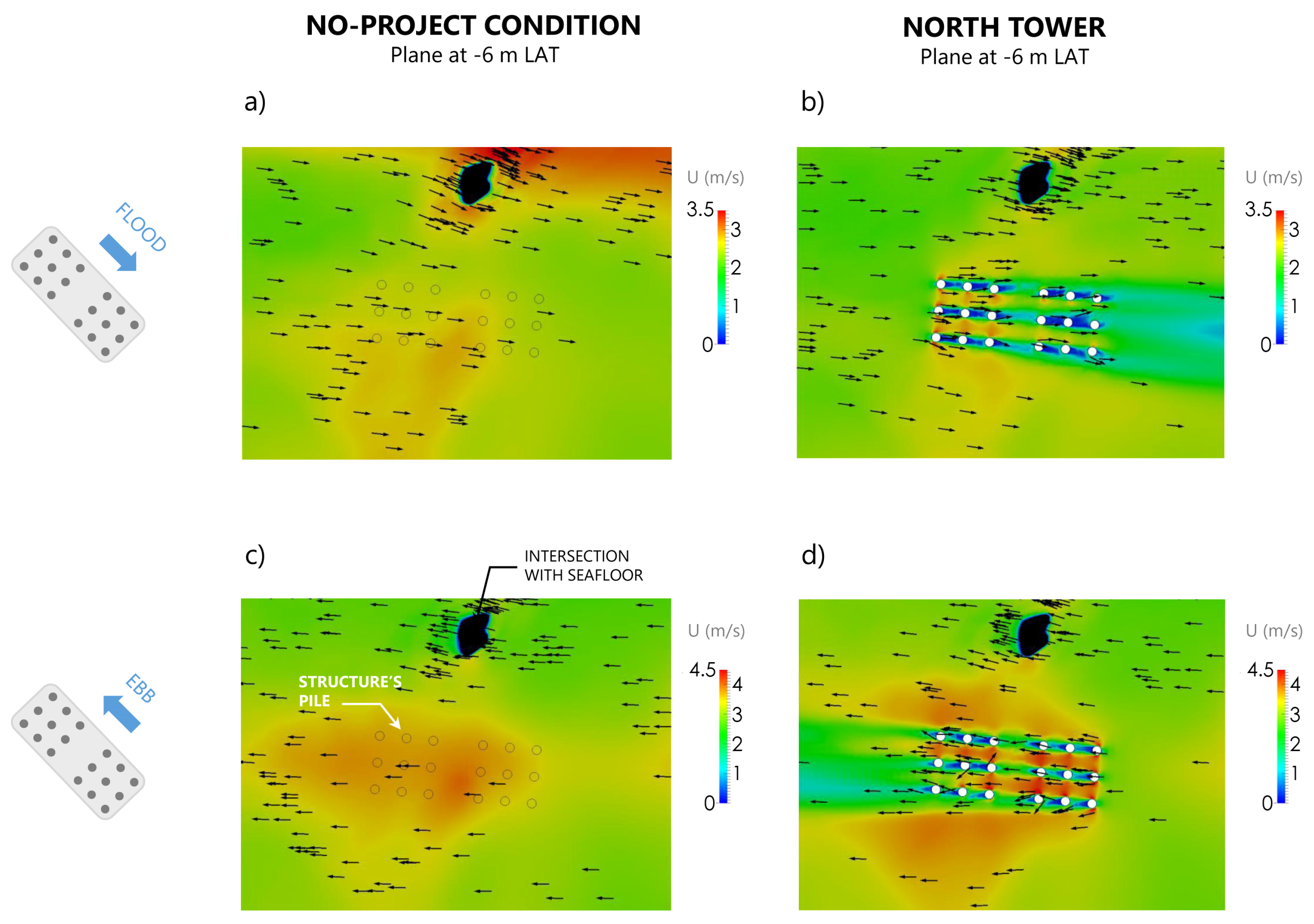
Figure 6 shows the velocity fields at −6 m LAT (Lowest Astronomical Tide) in the vicinity of the NT for the flood-tide and ebb-tide scenarios in the no-project condition and with the structure. The unperturbed flood-tide (Figure 6a) and ebb-tide flows (Figure 6c) show mild horizontal gradients reaching up to 3.0 m/s and 4.0 m/s, respectively. Once the structure is present, the flood-tide flow (Figure 6b) is drastically perturbed, increasing to localized speeds of up to 3.5 m/s in between piles to nearly stagnant conditions at the leeward side of each pile, as a consequence of individual wakes. For the ebb-tide flow (Figure 6d) speeds locally increase to up to 4.5 m/s, and there is a larger increase of flow speed around the group of piles. In both scenarios, there is also an overall reduction of the speed at the wake of the NT, which is heavily influenced by the pile group effect.
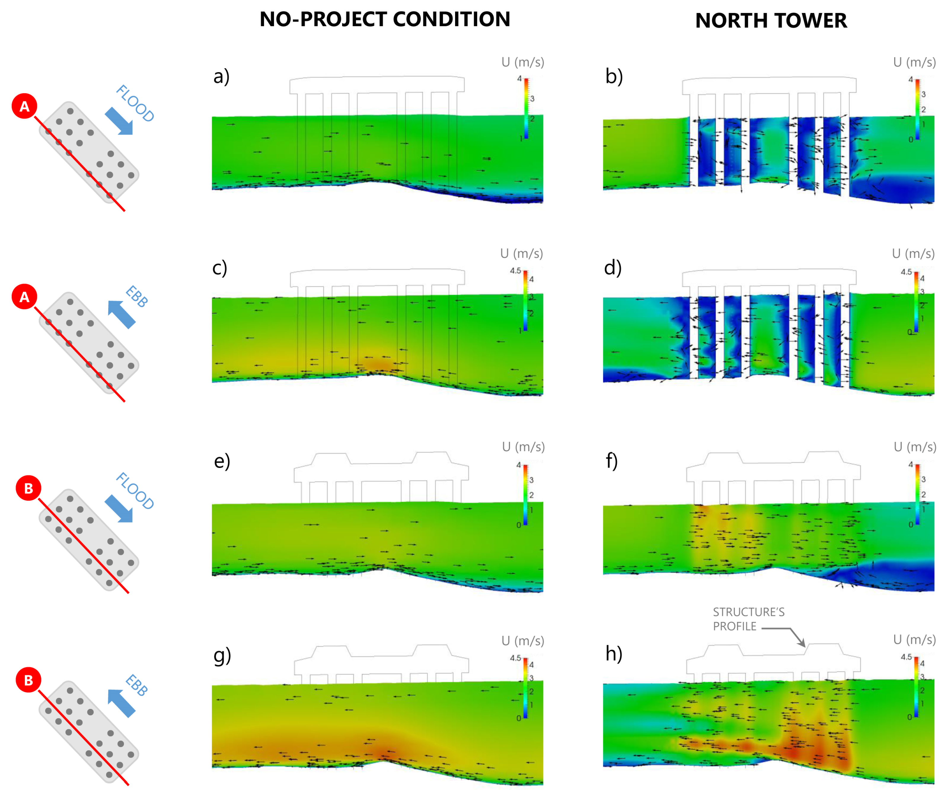
Figure 7 shows side views of velocity fields at vertical planes coinciding with the southern-most line of piles and between lines of piles in the NT for both scenarios in the no-project condition and with the structure. The unperturbed flood-tide flow (Figure 7a,e) shows relatively uniform speeds of nearly 2.5 m/s above a very confined bottom boundary layer. In contrast, for the ebb-tide flow (Figure 7c,g), there is a marked vertical gradient with speeds up to 4.0 m/s immediately above a thin bottom boundary layer which decrease to nearly 2.5 m/s towards the surface. This pattern is caused by the varying topography at the Tower’s basis, which tend to contract the upstream streamlines, thus increasing the speed in the lower portion of the water column. Once the structure is present, both the flood-tide (Figure 7b) and ebb-tide flows (Figure 7d) are drastically reduced at the leeward side of each pile. Conversely, the speed increases to nearly 4.0 m/s in the upper portion of the water column for the flood-tide scenario (Figure 7f), and to 4.5 m/s for the ebb-tide scenario (Figure 7h), thus enhancing the speeding effect caused by the shallowing bathymetry.

3.2. Shear Stress around Bridge Piers

Turbulent shear stress around each pile is represented by τ ( t ) , where t is the time falling into the range 0 t Δ T , and Δ T is the simulation time introduced in Section 2.1. This stress was computed at every position ( x , y , z ) of the numerical domain. However, for design purposes, the maximum stress was computed close to the perimeter of each pile within the steady regime interval as follows:
τ w ( t ) = max 0 ϕ < 2 π τ ( r = R + ϵ , ϕ , t t * ) ,
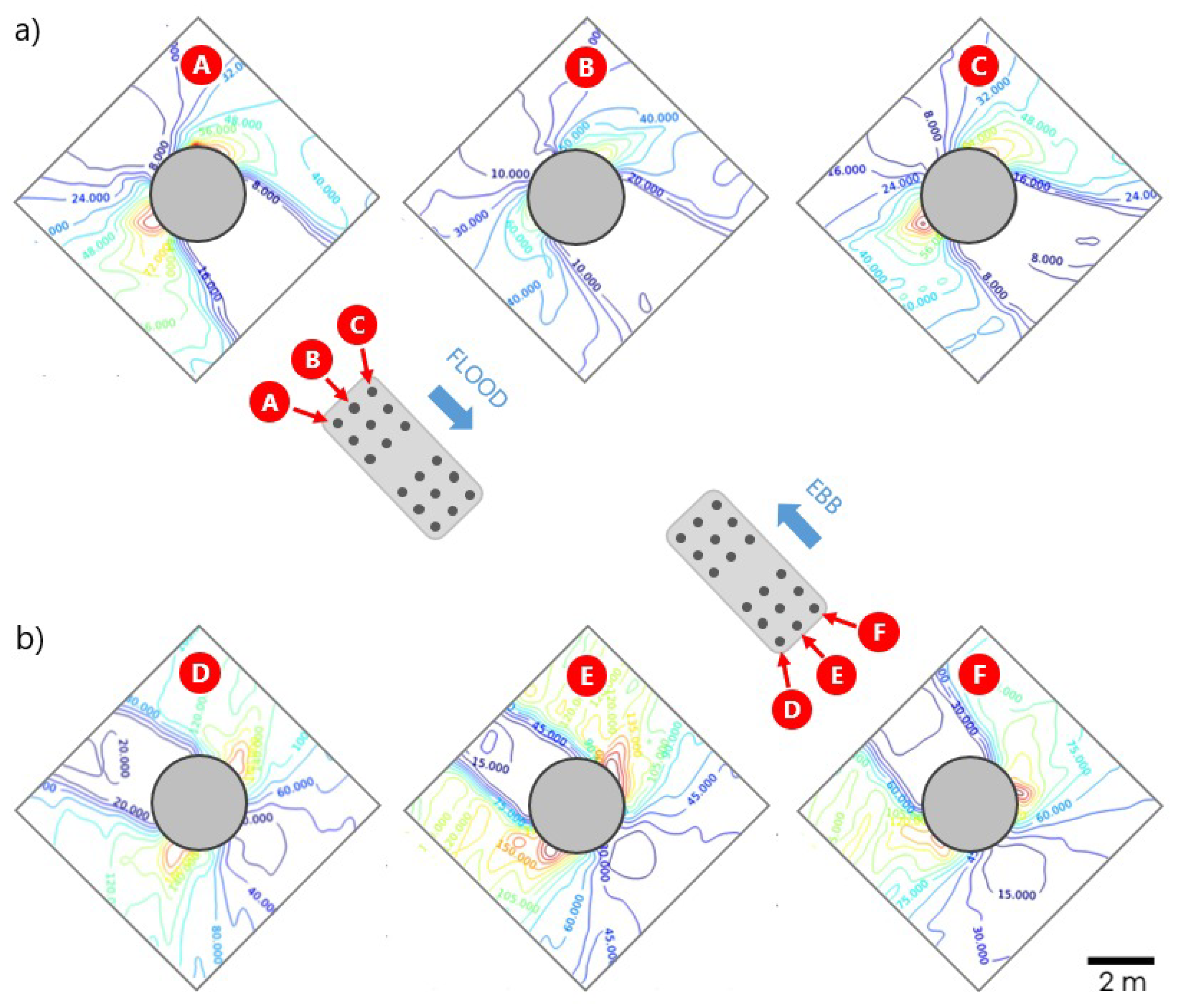
where t * is the instant where the incoming flow reaches a steady regime, ϵ 5 cm, r is a radial coordinate measured from the center of each pile, ϕ a polar angle and z a vertical coordinate directed upwards and centered in the pile (Figure 2c). The parameter τ w ( t ) was computed with a proprietary MATLAB code at the interception between pile’s plane and the seafloor, where the stress is expected to have maximum values. Note that even in the (upstream) steady regime, τ w ( t ) is not strictly constant because of the vortex shedding downstream each pile. Such dynamics continuously changes the flow patterns emphasizing the need of computing the shear stress at every time of the simulation, as proposed in Equation (18). Figure 8 shows, as example, the iso-contours of shear stress τ for an arbitrary time in the steady regime, around several piles at the NT for both, flood-tide and ebb-tide scenarios. Notice that high intensity stress values concentrate on the sides of the piles with respect to flow’s stream-wise direction, where significant abrasion is expected.
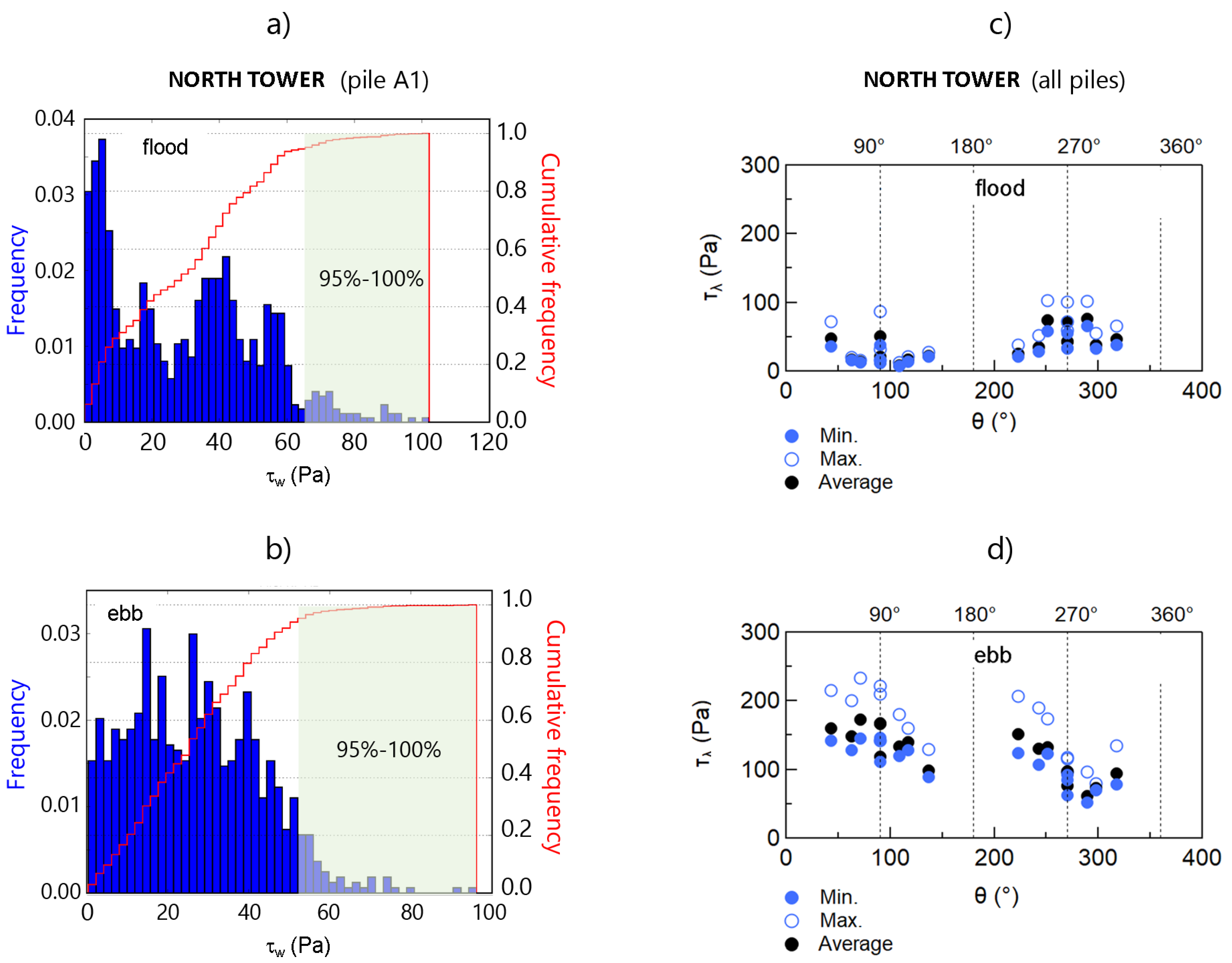
Figure 9 shows the frequency and cumulative frequency distributions of τ w ( t ) for an arbitrarily chosen pile at NT, for both flood and ebb-tide scenarios. The frequency here is understood as the number of times that a value of τ w occurs into a given class interval. The highest 5% of each histogram, hereinafter noted as τ λ , was used for further analysis (green shadowed box in Figure 9a,b). Minimum, maximum and average values of this subset were extracted for each pile ( τ λ m i n , τ λ m a x , τ λ a v e ), the distribution of which is shown in Figure 9c,d for flood and ebb-tide scenarios, respectively. Each set was compared for a range of polar angles θ (Figure 2c). Regardless of the statistical parameter, the highest values of shear stress falls into the range τ λ < 250 Pa, values which were finally used to build the erosion evolution curves with the SRICOS method [63], as explained in Section 3.3.

3.3. Erodibility and Scour Depth

Table 3 shows the erosion rate r ˙ obtained from RETA tests for NT samples. Results show that this material is always erodible and that r ˙ increases with the shear stress applied over the sample. In this case the concept of continuous and homogeneous erosion is coherent with theory described by Briaud [63]. In addition, Table 3 reveals that erosion occurs only once a threshold shear stress τ c is exceeded. This threshold is sample-dependent and it is not always possible to clearly identify it. However, these measurements allowed to build an empirical relation r ˙ ( τ ), such that r ˙ = 0 and Z ( t ) = 0 for τ τ c and, r ˙ > 0 and Z ( t ) > 0 otherwise. With these elements Equation (16) is rewritten as:
Z ( t ) = t r ˙ ( τ ) + t Z m a x 1 ,
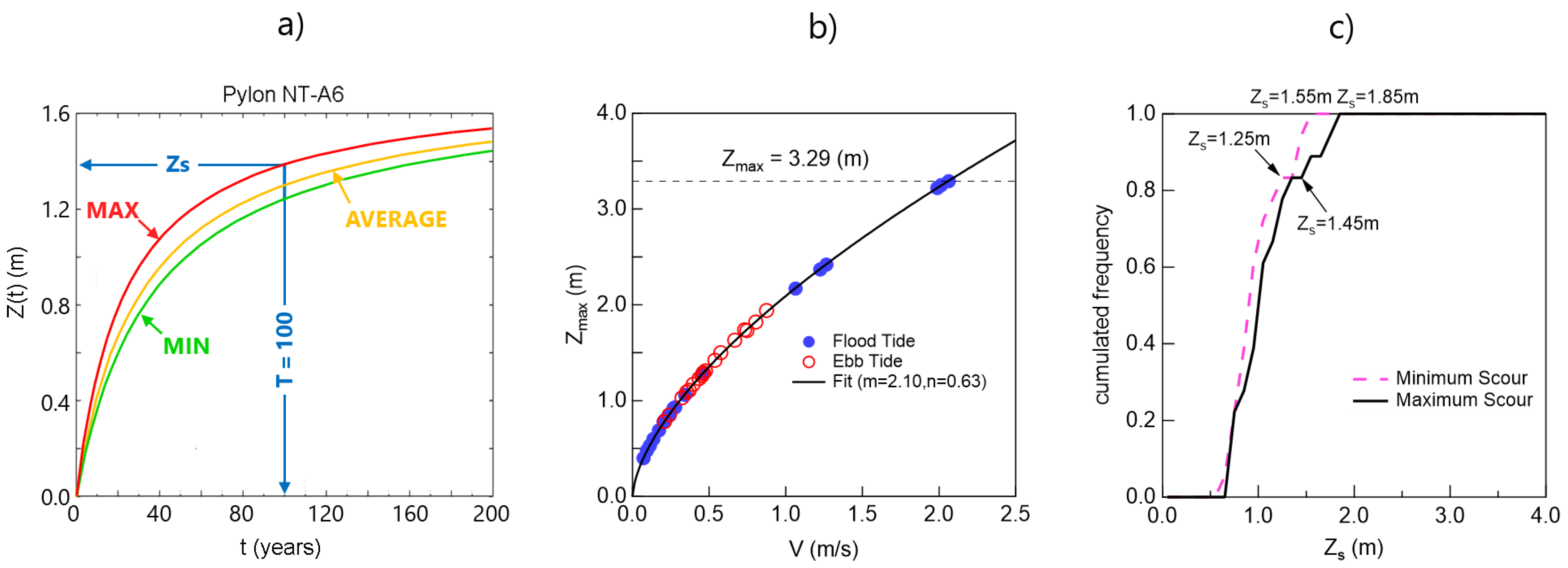
where Z m a x is the asymptotic erosion depth of the model when t , measured in meters, and depends on the Reynolds mean flow number estimated with OpenFoam. The erosion depth ( Z s ) estimated from this model for t = T is, of course, lower than Z m a x . In this model t is the real time, such that 0 t T where T is bridge’s lifetime. As already introduced, a subset of τ w ( t ) was extracted from each pile to estimate the erosion rates as required by SRICOS method. Such values, denoted as τ λ , correspond to the [ 95 % , 100 % ] interval from the cumulated frequency distribution shown in Figure 9a,b. By combining the empirical curves r ˙ ( τ ) obtained from RETA tests and the statistical parameters τ λ m i n , τ λ m a x , τ λ a v e , we interpolated a minimum, maximum and average rates, r ˙ m i n , r ˙ m a x and r ˙ a v e , for each pier. From these parameters, minimum, maximum and average evolution curves of erosion around each pile of the NT were computed (Figure 10a). The distribution of Z m a x for each pile is depicted in Figure 10b, as a function of the upstream velocity, V = max 0 z < h V ( z ) , estimated for ebb and flood-tide scenarios. Figure 2 shows the reference points where such velocity was measured at both sites at a given plane z. The local velocity scale V ( z ) was calculated as follows:
V ( z ) = u ¯ ( z ) 2 + v ¯ ( z ) 2 + w ¯ ( z ) 2 ,
where ( u ¯ , v ¯ , w ¯ ) are the time-averaged velocity components estimated from OpenFoam in ( x , y , z ) directions, respectively. These averages were, once again, estimated into a steady regime. An advantage of SRICOS approach is the possibility of integrating the erosive action on each pile estimated for flood and ebb-tide scenarios, into a variable approximating flow velocity V ( t ) , and, in turn, the shear stress around each pile τ ( t ) , for t [ 0 , T ] . We herein assumed V ( t ) only takes a square-wave type series with binary values for the ebb and flood-tide scenarios acting during bridge’s lifetime, for each pile. The parameter Z m a x is described by the next fitting function, for both tide scenarios:
Z m a x = m V n
where ( m , n ) = ( 2.10 , 0.63 ) are fitting parameters. Figure 10c shows the cumulative frequency distribution of the erosion depth for t = T , Z s ( T ) obtained when considering r ˙ = r ˙ m i n and r ˙ = r ˙ m a x . Around 80% of data falls into the range Z s 1.45 m, with a maximum erosion value of ( Z s ) m a x = 1.85 m. No significant differences are observed between both curves, a consequence of the low differences between the curves in Figure 10a.

4. Results for Central Tower

4.1. Flow Field

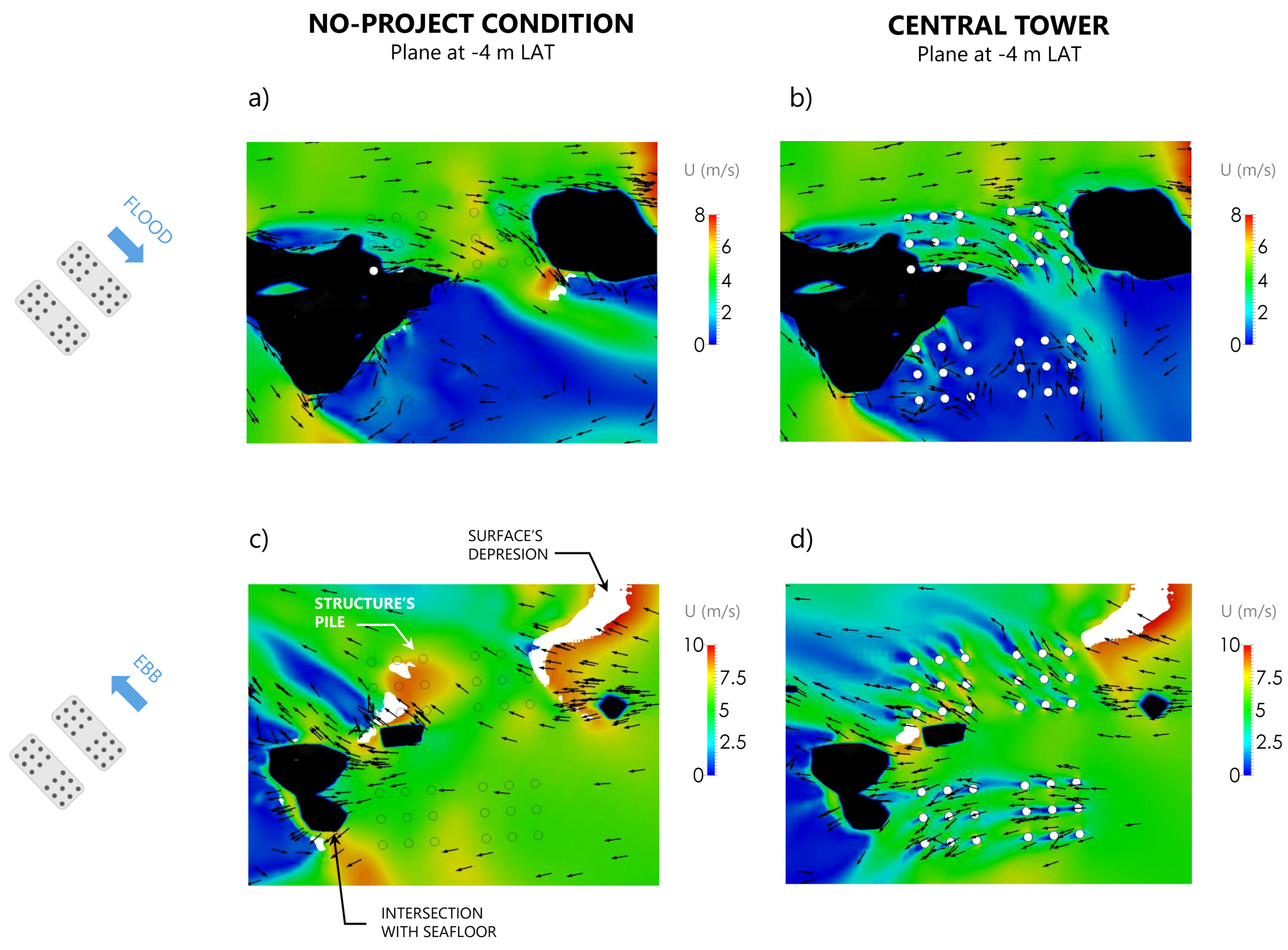
Figure 11 shows the velocity fields at −4 m LAT in the vicinity of the CT for the flood-tide and ebb-tide scenarios in the no-project condition and with the future assemble of 36 piles. The flood-tide flow is naturally perturbed by Roca Remolinos generating a recirculating pattern with very small speeds on the southern array of 18 piles (Figure 11a). In the northern array of piles, in contrast, speeds reach up to 6 m/s because of the funnelling effect of bathymetry. As in the NT, the ebb-tide in the CT shows larger speeds than the flood-tide (Figure 11c), with speeds of up to 10 m/s in some piles and significant depressions of the surface’s profile downstream two of the shallows shaded in black. The flood-tide flow is locally reduced by the presence of the northern array of piles (Figure 11b), but the speed reduction is moderate. For the ebb-tide flow (Figure 11d) speeds are locally reduced in the wake of individual piles, being the group effect larger in the northern array of piles.
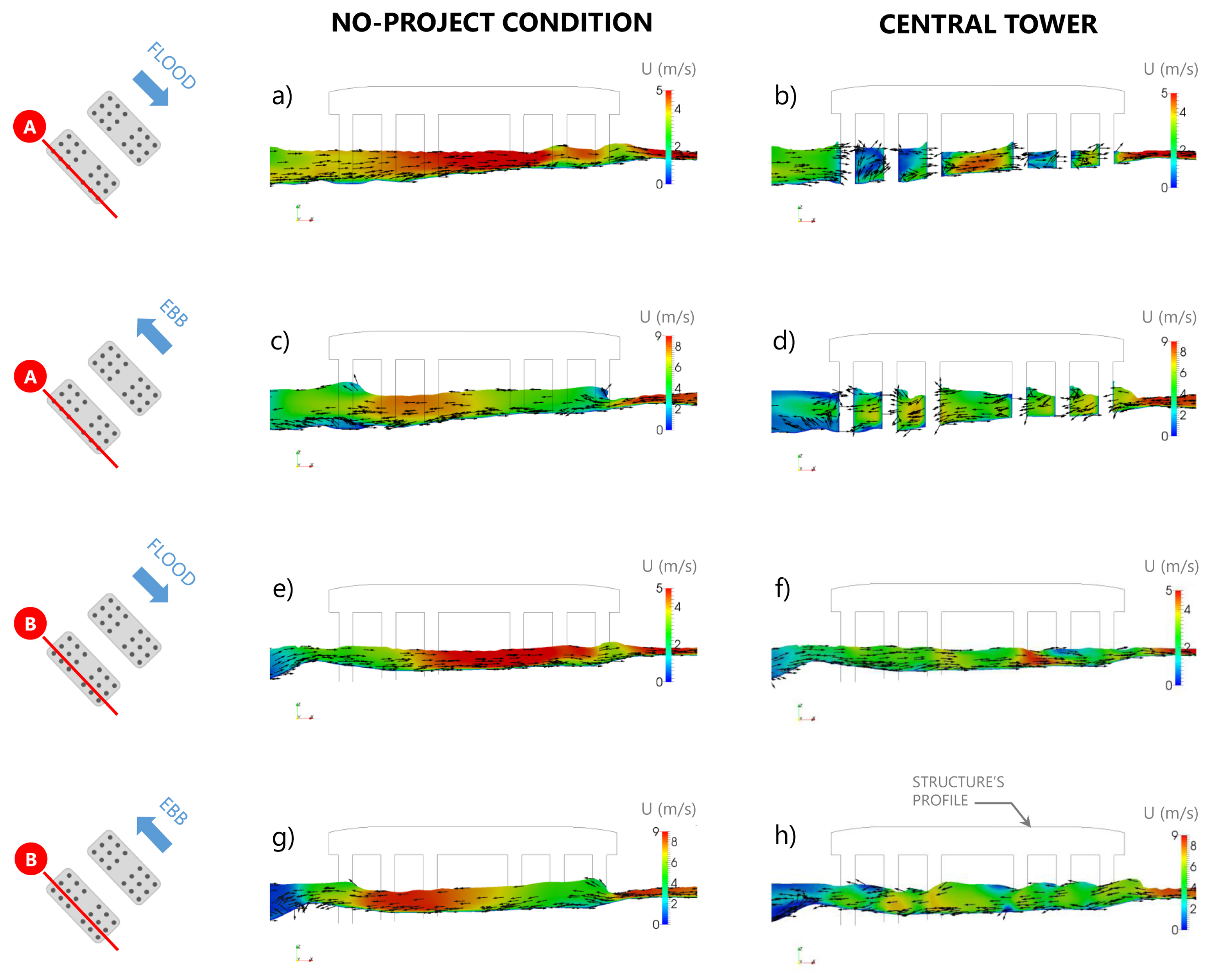
Figure 12 shows side views of velocity fields at vertical planes coinciding with the southern-most line of piles and between lines of piles in the CT for the flood-tide and ebb tide-scenarios in the no-project condition and with the structure. For this site, mean flow’s velocity significantly increase given the small flow’s depths in this area. The unperturbed flood-tide flow (Figure 12a,e) shows speeds of nearly 5.0 m/s while for the ebb-tide flow (Figure 12c,g), speeds reach 9.0 m/s under a near critical flow, evidenced by localized hydraulic jumps caused by the varying topography. Once the structure is present, both the flood-tide (Figure 12b,f) and ebb-tide flows (Figure 12d,h) are reduced and spatial gradients become larger due to the presence of piles. Once again, the velocity field is perturbed by the group of piles, but to a lesser degree when compared to the NT.
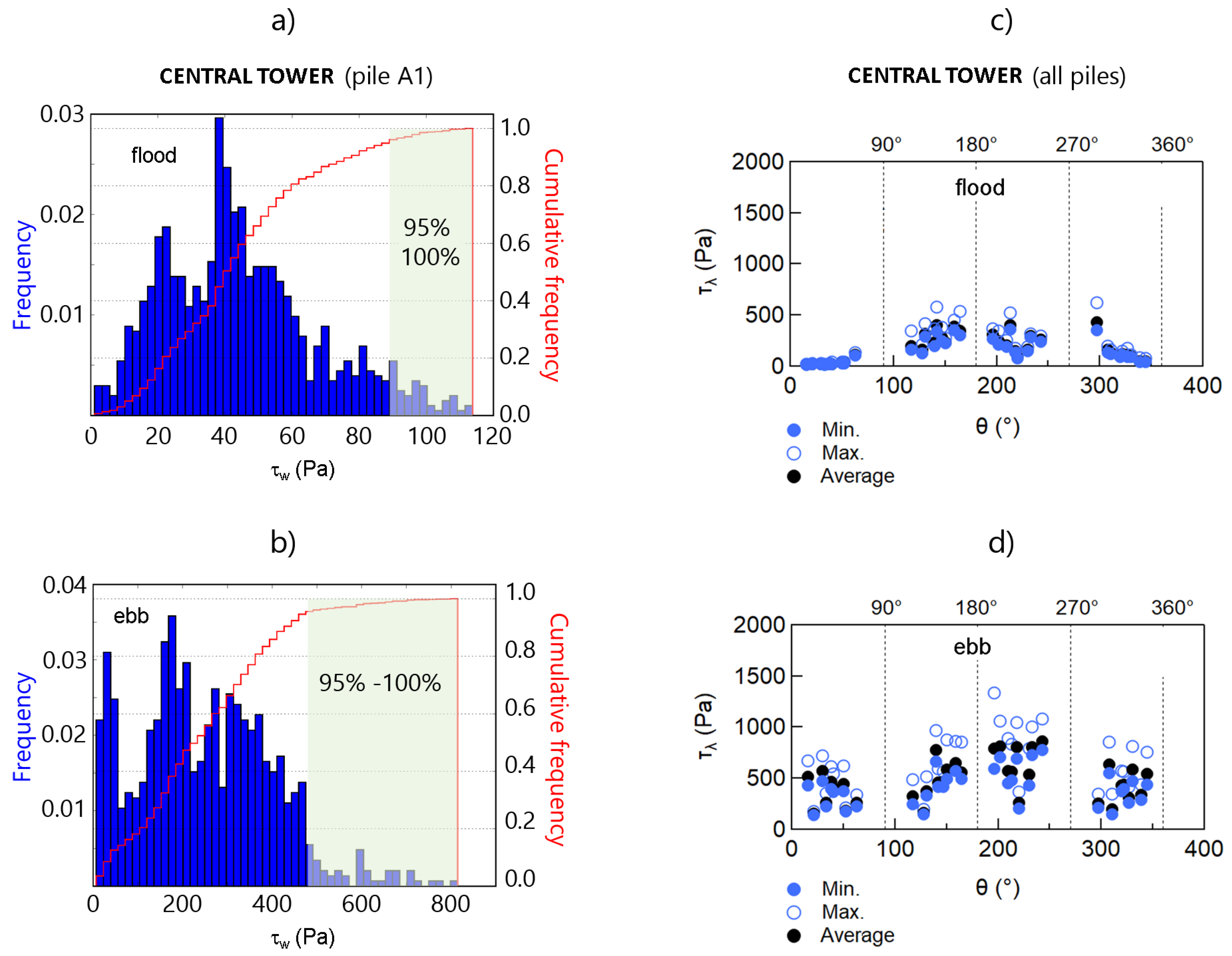
It is also clear from Figure 13 that the ebb-tide scenario plays a leading role on the erosion process at the CT. Particularly, Figure 13c,d show values of shear stress up to 1500 Pa for an ebb-tide scenario, that is, at least 3 times higher than values observed for NT. In addition, the irregular bathymetry at CT site induces significant changes in the velocity field between the different sections of the group of piles, suggesting that the distribution of shear stress is highly variable throughout the perimeter of the group and around each pile. These observations emphasize the need of locally determining the velocity and shear stress around each pile when dealing with a complex bathymetry, as suggested in [48].

4.2. Erodibility and Scour Depth

Table 4 shows the erosion rate r ˙ obtained from RETA tests for samples obtained at Remolinos rock. These results significantly differ with those at NT and constitute a clear evidence of the heterogeneous geological nature of Chacao Channel. The samples showed low or susceptibility to hydrodynamic erosion, even days after the RETA tests (samples RR4 and RR5). Only samples RR2 and RR3 showed non-zero erosion rates, a sign that a part of the rock could be eventually eroded by flow conditions. For this part of the rock, the SRICOS method can be applied. However, sample RR4 showed high erosion rates of r ˙ > 400 mm/year, values explained by large pieces of rock suddenly removed due to increasing shear stresses, remaining the rest of the sample unperturbed (Figure 5d). For this case, the concept of continuous and homogeneous erosion described by Briaud [63] becomes misleading, forcing to explore alternative methods. The erodibility index K was then used, taking into account the information obtained from geological drilling of the site [6].
Table 5 shows the values used to compute this index, which turned to be K = 11.66. This calculation assumed an almost soft rock whose possible fractures are homogeneously distributed throughout the sample. We also assumed the sample contained cemented fissures, filled with a cohesive-like material or crushed rock elements. Underwater explorations and qualitative analysis conducted on samples provided reasonable support to these hypotheses.
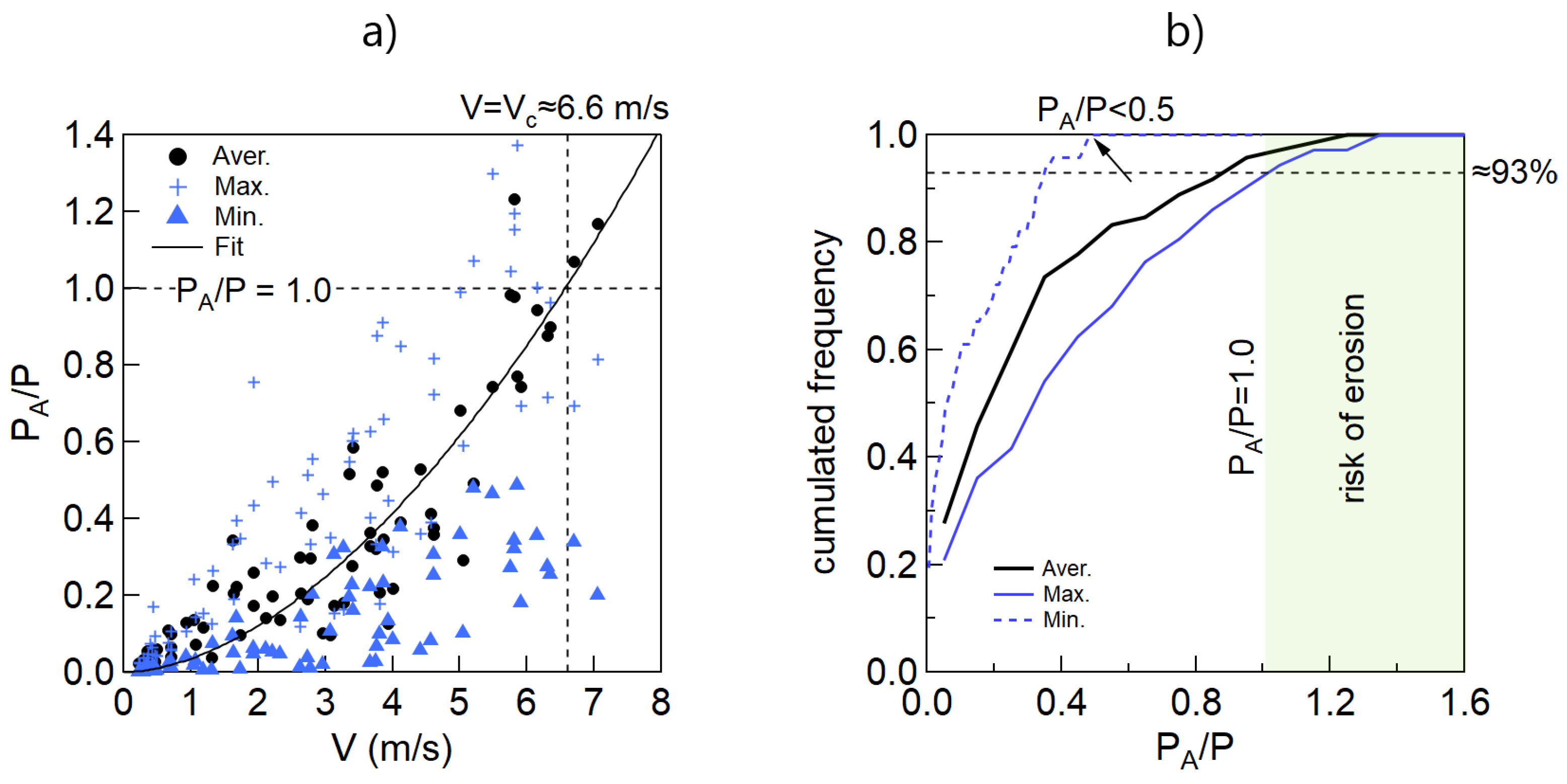
Using this index, the erosion threshold stream power was estimated from Equation (15) as P = K 0.75 = 6.31 kWm−2. This value can be compared with the available stream power P A , estimated from Equation (14) as P A = τ V , where τ and V are representative scales for shear stress and velocity, respectively. For this study such velocity scale is given by the upstream flow velocity defined by Equation (20), whereas τ corresponds to τ λ m i n , τ λ a v e and τ λ m a x . This choice is in agreement with recommendations proposed by Arneson et al. [48] who suggests the use of local variables for a better estimation of P A , thus rock scour around bridges. Using data of Figure 13c,d and the velocities calculated with OpenFoam, the hydrodynamic available stream power P A was estimated for flood-tide and ebb-tide scenarios around each pile. These estimations led to minimum, average and maximum values of P A . Figure 14a compares P A / P with the approximating velocity V of each pile, for both hydrodynamic scenarios. The ratio P A / P > 1 represents an estimate of the effective probability of rock erosion, otherwise not. The black line is a fit of average data, represented by the function:
P A P = m ^ V n ^
where ( m ^ , n ^ ) = ( 0.035 , 1.78 ) are fitting parameters. Note that from the critical condition P A / P = 1 , we obtain that V c = ( 1 / m ^ ) 1 / n ^ , a critical velocity above which rock scour could occur around a pile. A simple evaluation gives that V c 6.6 m/s. To delve into the plot of Figure 14b, the cumulative frequency curve of P A / P was built for the minimum, maximum and average values of P A . Note that only 7% of data at CT site satisfy the condition P A / P > 1, implying the risk of erosion is very low for this site. In addition, this value is grounded on extremely conservative conditions when calculating the threshold erosion power and the strength of the rock.
If we focus in the range 1.0 < P A / P < 1.37 and if some scour risk is assumed, from Equation (16) and the guidelines by Arneson et al. [48], it is found that Z s / D 3.43 . This ratio would lead to the range 7.48 m < Z s < 8.59 m for D = 2.5 m. However, these values are extremely high and have to be carefully considered for design purposes. In this context, the scour depth for this site was estimated considering the erodible part of the rock according to RETA tests reported in Table 4. For this purpose it was essentially adopted the same calculation procedure as in NT. Estimations of local scour depth led to a more reasonable range 0.01 m < Z s < 0.63 m for this tower.

5. Discussion

In many engineering projects, the estimation of local scour at bridge piers can be a routine calculation, particularly when dealing with granular beds. However, this is not the case when dealing with cemented cohesive or rocky beds, like those in NT and CT. Most of existing formulas are no longer applicable for these complex soils. To reduce the uncertainty in scour estimates, a combination of 3D computational simulations, experimental tests (RETA) and the adaptation of empirical formulas provide a way to achieve safe designs when dealing with complex materials and environment conditions. In this context, a differentiated analysis is performed at both sites as follows.

5.1. About North Tower

RETA tests show that samples at NT are always erodible and the erosion is almost homogeneous (Figure 4e). According to Keaton et al. [27], cavitation is also unlikely for the dominant hydraulic conditions at this site. Consequently, an erosion curve Z ( t ) was built from the velocity time series V ( t ) around each pile. These series were assumed as the combination of pure flood-ebb tides acting during bridge’s lifetime T = 100 years, from which a maximum long-term scour depth Z m a x was determined using SRICOS methodology. The combination of various conservative assumptions (e.g., velocity time series defined from the highest tidal ranges on a 19 years cycle and the selection of the highest 5% of shear stresses of the most critical pile) provided relatively high but conservative values of Z s for this type of materials. Another advantage of this approach is the feasibility of building a relation between τ λ and r ˙ , which explicitly considers the local conditions of each site. Though the values of r ˙ used by Briaud et al. [63] were estimated from piston-type devices (e.g., SERF flume [38]), the hydrodynamic setting in RETA tests is not significantly different, that is, a persistent shear stress τ acting on sample’s surface.
We remark that the decreasing slope curve r ˙ ( τ λ ) proposed by SRICOS methodology was not observed in this study. Instead, a cloud of points with significant scattering was obtained, therefore, the erosion curve Z ( t ) adopted for design purposes showed an intrinsic uncertainty related to the substrate’s nature and the variability of the erosion rate r ˙ ( τ λ ) . To reduce this uncertainty, minimum, average and maximum erosion curves were built for r ˙ m i n , r ˙ a v e and r ˙ m a x , respectively. By following this strategy, we determined a more reasonable maximum scour depth at each pile, falling into the range 0.67 m < Z s < 1.82 m for this site (cf. Figure 10c). Just for comparison, these results were contrasted with the classical HEC18 formulae proposed by Richardson and Davis [65], recently updated by Shan et al. [66], and proven to be applicable to a wide range of conditions and type of bridges by [67]. The formulae reads as:
( Z s ) H E C 18 D = 2.0 K 1 K 2 K 3 K 4 h D 0.35 F r 0.43
where D is the diameter of the pile and F r = V / g h the Froude number of the approximating flow. The coefficients K 1 , K 2 , K 3 and K 4 consider corrections for pier nose shape ( K 1 = 1.0 ), the angle of attack of the flow ( K 2 = 1.0 ), bed condition ( K 3 = 1.1 ) and bed material armoring ( K 4 = 0.6 ). In addition, the next parameter was introduced:
ξ = ( Z s ) H E C 18 ( Z s ) S R I C O S
Figure 15 shows the distribution of ξ versus the Froude number (Figure 15a) and the relative depth h / D (Figure 15b), for flood and ebb-tide scenarios. Notice that most of points fall into the region ξ < 1 , meaning that in this region HEC-18 formulae underestimates the scour depth obtained from SRICOS methodology. Just for a few conditions, the parameter ξ is greater than 1. Then, from a conservative point of view, the method proposed by Briaud et al. [58,63] minimizes uncertainties in the design process. Although Equation (23) provides a simple way to estimate scour depth for many materials, it must be carefully used according to recommendations proposed by Keaton et al. [27].

5.2. About Central Tower

At CT site the scouring mechanism is complex because of the three dimensionality of the flow [68] (e.g., existence of bow waves, horseshoe and wake vortexes), the characteristics of the soil and the structure itself. Then, the estimation of scour requires more elements than those for single piles. The application of the EIM method [25] leads to high erosion threshold powers ( P ( K ) ) and a very low probability of erosion at this site. Only 7% of data shows that erosion could arise for the analysed samples, but such probability is a combination of extreme conservative conditions which will be seldom reached during bridge’s lifetime. Even more, if some scour is accepted to occur, Equation (17) leads to values of 7.48 m < Z s < 8.59 m, which are very high compared with those obtained at the more erodible material found in the NT. This contradicts evidence from underwater explorations around Remolinos rock, which showed few pieces of rock removed by currents. Then, there’s a strong reason to consider this theoretical scour range unrealistic. In addition, Annandale [25] proposed another following expression for estimating Z s , which was also used in the present study. This equation led to a similar range of scour depths and, once again, relies on a large amount of samples which were nonexistent in CT.
An important aspect of this study is related with key engineering decisions adopted in the project. The idea that Remolinos rock presents a very-low risk of erosion was difficult to accept by design experts. Thus, scour depth estimations were anyway conducted on those parts of the rock showing some erodibility according to RETA tests. In this context, the procedure used in NT was adopted for this site, leading to a scour depth Z s = 0.63 m, a moderate value that agrees with the order of magnitude reported by Arneson et al. [48].
Several improvements could be achieved to reduce the uncertainty of scour estimates at this site. For example, a rock scanner would provide valuable information of the joints’ structure of the rock, the faces prone to erosion and its strength. Unfortunately, budget limitations and the strict deadlines of the project inhibited the acquisition of several samples at the CT site. Additionally, the underwater exploration was restricted to nearly 10 min during slack tide (i.e., the shift from ebb to flood tides when speeds are reduced), which allowed highly qualified divers to recover only few samples from Remolinos rock. This condition imposed a serious restriction for this site, limiting our knowledge about the overall erodibility of the material.

5.3. Design Value of Scour Depth

Although the scour depth Z s was estimated for extreme conditions, an overall safety factor f s was considered for each pile. This factor was calculated as f s = f ¯ 1 f ¯ 2 , where f ¯ k = ( 1 / N ) i = 1 N f k i is the mean value of f k , where N is the number of piles at each tower and k = 1 , 2 . Unfortunately, there is no physically meaningful estimation for these factors and different visions across disciplines involved in their definition persist, as pointed by Briaud et al. [69]. In principle, both factors can be estimated as follows:
f 1 i = 1 + ( Z s ) m a x ( Z s ) m a x f 2 i = ( Z s ) m a x ( Z s ) a v e
The factor f 1 i compares the maximum local scour depth ( Z s ) m a x and the safe scour depth 1 + ( Z s ) m a x of each pile. By contrast, f 2 i compares ( Z s ) m a x with the probable erosion obtained from average flow conditions represented by ( Z s ) a v e , for i = 1 , . . . , N . Both quantities, ( Z s ) m a x and ( Z s ) a v e , are obtained from Figure 10a at t = T = 100 years. However, the application of Equation (25) leads to extremely high values for f 1 (e.g., in CT reach values of up to 50), which look unrealistic and not practical for design purposes. A statistical treatment was therefore applied by discarding abnormally high values, leading to average values of f ¯ 1 = 1.15 and 1.35 for CT and NT, respectively. A same procedure was adopted for f 2 , obtaining in average f ¯ 2 = 1.46 and 1.07 for CT and NT, respectively. With these assumptions, the equivalent safety factor was estimated as f s = 1.67 and 1.44 at both sites. The final scour depth for design Z D calculated as follows:
Z D = f s Z s + δ
where Z s is the overall maximum scour depth at each tower and δ is an additional depth of foundation chosen according to designers experience. The final scour depth is summarised in Table 6.

6. Conclusions

The pier scour depth at two towers of the Chacao Channel bridge was estimated considering the non-conventional nature of the substrates, the geometry of piles and local hydrodynamic conditions at both sites. The erodibility properties and scour depth were constrained by the limitations of existing formulas and the lack of data on the geological conditions of the substrates, which altogether forced us to propose an integrated approach to properly account for soil’s nature.
At NT site, a simple adaptation of SRICOS method lead to reasonable values of the scour depth, that is, Z s 1.82 m, which turned to 2.82 m considering safety criteria. This site is characterized by a highly cohesive bed with high resistance to hydrodynamic erosion, but not quite high to be non-erodible. In contrast, the nature of the soil at CT site suggested the use of the EIM erosion index, showing large uncertainties when applied to Remolinos rock. Although erosion risk was estimated to be very low for this substrate, a conservative approach considered a non-zero safety scour depth of Z s 0.63 m for this site, which turned 1.63 m considering safety criteria. After several discussions with the Ministry of Public Works, we proposed to complement these calculations with a monitoring plan in order to control possible bedrock removals during the bridge’s lifetime.
This case study reveals that a combination of numerical modeling, experimental tests and long-term scour monitoring plan could provide a reasonable strategy to reduce the uncertainty when estimating the scour depth around bridges in complex and heterogeneous substrates with scarce information about geology. Additionally, a more detailed characterisation of the CT site, and in less degree of the NT site, would have further contributed for a better estimation of scour depth and the susceptibility to erosion.
To conclude, literature still lacks of a general and confident formula for rock scour that considers all the mechanical properties of a rock, the involved erosion mechanisms, the local hydrodynamic patterns, and pile group effects, among other variables. This restriction was a key aspect of this study and is a challenge that deserves to be afforded in future hydraulic engineering studies.

Author Contributions

Conceptualization, L.Z., F.L., F.M. and P.W.; methodology, L.Z., F.M. and P.W.; formal analysis, F.M.; investigation, F.M.; data curation, F.M.; writing—original draft preparation, F.M.; writing—review and editing, P.W.; supervision, P.W. All authors have read and agreed to the published version of the manuscript.

Funding

This study was funded by Skyring Marine Ltda. (Chile). The first author also thanks the grant Investigador Emergente, Code 039.329/2022, from Vicerrectoría de Investigación of the Pontificia Universidad Católica de Valparaíso.

Acknowledgments

The authors acknowledge the information and consent given by the company Skyring Marine Ltda.(Chile) to publish this study. We also thanks the facilities given by Instituto Nacional de Hidráulica (INH), Jaime Cotroneo (Hydraulic Engineer at INH) and Enrique Galecio (former Hydraulic Engineer at INH) for their valuable contribution during the project. The authors also thanks the company GeoHazards (EEUU) for conducting the RETA tests and provide valuable information about the erodibility of the samples.

Conflicts of Interest

The authors declare no conflict of interest.

References

  1. Syngros, K.; Dobry, R.; Leventis, G.E. Chacao Channel Bridge–the Design Challenges. In Proceedings of the International Conference on Case Histories in Geotechnical Engineering—Sixth International Conference on Case Histories in Geotechnical Engineering, Arlington, VA, USA, 11–16 August 2008. [Google Scholar]
  2. Forsberg, T. The challenge of constructing a bridge over the Chacao channel. In Proceedings of the Fourth Symposium on Strait Crossings, Bergen, Norway, 2–5 September 2001; p. 345. [Google Scholar]
  3. Forsberg, T. Multi-span suspension bridges. Int. J. Steel Struct. 2001, 1, 63–73. [Google Scholar]
  4. Valenzuela, M.A.; Márquez, M.A. Chacao Suspension Bridge: Tender and Technical Challenges. In Proceedings of the IABSE Symposium: Engineering for Progress, Nature and People, Madrid, Spain, 3–5 September 2014; pp. 2516–2523. [Google Scholar]
  5. Caceres, M.; Valle-Levinson, A.; Atkinson, L. Observations of cross-channel structure of flow in an energetic tidal channel. J. Geophys. Res. Ocean. 2003, 108, 968. [Google Scholar] [CrossRef]
  6. Cuatro; Cowi, I. Final Report—Engineering Study—Volumes 1 through 9. Technical Report, Ingeneria Cuatro/Cowi. 2001; (not available online). [Google Scholar]
  7. Aiken, C.M. Barotropic tides of the Chilean Inland Sea and their sensitivity to basin geometry. J. Geophys. Res. Ocean. 2008, 113, 4593. [Google Scholar] [CrossRef]
  8. Soto-Mardones, L.; Letelier, J.; Salinas, S.; Pinillas, E.; Belmar, J.P. Análisis de parámetros oceanográficos y atmosféricos del Seno de Reloncaví. Gayana (Concepción) 2009, 73, 141–155. [Google Scholar] [CrossRef]
  9. Warren, R.; Larsen, J.; Svendsen, H. Chacao Channel, an Extreme Application of MIKE 21; COWI Consulting Engineers and Planners AS: Lyngby, Denmark, 2007. [Google Scholar]
  10. Marín, V.H.; Campuzano, F.J. Un modelo hidrodinámico barotrópico para los fiordos australes de Chile entre los 41S y los 46S. Cienc. Tecnol. Del Mar 2008, 31, 125–136. [Google Scholar]
  11. Sepúlveda, I.; Winckler, P.; Cáceres, M. Hydrodynamic modeling of tidal currents and power extraction in Chacao Channel, Chile. In Proceedings of the 4th Annual Marine Renewable Energy Technical Conference, University of Massachusetts Dartmouth, North Dartmouth, MA, USA, 10 January 2013. [Google Scholar]
  12. De la Fuente, L.; Miguel, N.E. Hydrodynamic Modelling of Tidal Currents at Chacao Channel for a Preliminary Energy Resource Assessment. Master’s Thesis, Pontificia Universidad Católica de Chile, Escuela de Ingeniería, Santiago, Chile, 2012. [Google Scholar]
  13. Winckler, P.; Sepúlveda, I.; Aron, F.; Contreras-López, M. How do tides and tsunamis interact in a highly energetic channel? The case of canal Chacao, Chile. J. Geophys. Res. Ocean. 2017, 122, 9605–9624. [Google Scholar] [CrossRef] [Green Version]
  14. Peña, Á.; Valenzuela, M.; Márquez, M.; Pinto, H. Requerimientos geotécnicos mínimos para el diseño de fundaciones de puentes tradicionales y singulares: Puente Colgante Chacao. Rev. Construcción 2017, 16, 498–505. [Google Scholar] [CrossRef] [Green Version]
  15. Melville, B.W.; Coleman, S.E. Bridge Scour; Water Resources Publications LLC: Highlands Ranch, CO, USA, 2000. [Google Scholar]
  16. Ettema, R. Scour at Bridge Piers—Report No 216; Technical Report; University of Auckland: Auckland, New Zealand, 1980. [Google Scholar]
  17. Pizarro, A.; Manfreda, S.; Tubaldi, E. The science behind scour at bridge foundations: A review. Water 2020, 12, 374. [Google Scholar] [CrossRef] [Green Version]
  18. Shen, H.W.; Schneider, V.R.; Karaki, S. Local scour around bridge piers. J. Hydraul. Div. 1969, 95, 1919–1940. [Google Scholar] [CrossRef]
  19. Chiew, Y.M.; Melville, B.W. Local scour around bridge piers. J. Hydraul. Res. 1987, 25, 15–26. [Google Scholar] [CrossRef]
  20. May, R.; Ackers, J.; Kirby, A. Manual on Scour at Bridges and Other Hydraulic Structures; Ciria: London, UK, 2002; Volume 551. [Google Scholar]
  21. Annandale, G.W.; Kirsten, H.A. On the erodibility of rock and other earth materials. In Proceedings of the Hydraulic Engineering, Buffalo, NY, USA, 1–5 August 1994; pp. 68–72. [Google Scholar]
  22. Annandale, G. Erodibility. J. Hydraul. Res. 1995, 33, 471–494. [Google Scholar] [CrossRef]
  23. Annandale, G.W. Prediction of scour at bridge pier foundations founded on rock and other earth materials. Transp. Res. Rec. 2000, 1696, 67–70. [Google Scholar] [CrossRef]
  24. Annandale, G.; Smith, S. Calculation of Bridge Pier Scour Using the Erodibility Index Method; Technical Report; Colorado Department of Transportation: Denver, CO, USA, 2001.
  25. Annandale, G. Scour Technology: Mechanics and Engineering Practice; McGraw Hill Professional: New York, NY, USA, 2005. [Google Scholar]
  26. Annandale, G. Current state-of-the-art Rock Scouring Technology. In Geotechnics of Soil Erosion; ASCE: Denver, CO, USA, 2007; pp. 1–12. [Google Scholar]
  27. Keaton, J.R.; Mishra, S.K.; Clopper, P.E. Scour at Bridge Foundations on Rock; Transportation Research Board: Washington, DC, USA, 2012; Volume 717.
  28. Bloomquist, D. Erosion of Cored Samples for the Chacao Channel Bridge Project Chile, South America. Interim Report; Technical Report; GeoHazards Co.: Gainesville, FL, USA, 2017. [Google Scholar]
  29. Marine, S. Proyecto Puente Chacao, Ingeniería Básica. Estudio de Socavación y Erosión, CHB-CPC-DGN-RPT-0282; Technical Report; Skyring Marine Ltd.: Valparaíso, Chile, 2017. [Google Scholar]
  30. The OpenFOAM Foundation. 2014. Available online: https://scholar.google.ca/scholar?hl=zh-TW&as_sdt=0%2C5&q=The+OpenFOAM+Foundation.+2014.&btnG= (accessed on 11 November 2022).
  31. Pope, S.B. Turbulent Flows; Cambridge University Press: Cambridge, UK, 2000. [Google Scholar]
  32. Menter, F.R. Improved Two-Equation K-Omega Turbulence Models for Aerodynamic Flows—Technical Memorandum 103975; Technical Report; NASA Ames Research Center Moffett Field: Mountain View, CA, USA, 1992.
  33. Menter, F.R. Two-equation eddy-viscosity turbulence models for engineering applications. AIAA J. 1994, 32, 1598–1605. [Google Scholar] [CrossRef] [Green Version]
  34. Ahrens, J.; Geveci, B.; Law, C. Paraview: An End-user Tool for Large Data Visualization. 2005, Volume 717. Available online: https://datascience.dsscale.org/wp-content/uploads/2016/06/ParaView.pdf (accessed on 29 November 2022).
  35. Fluent, A. 12.0 User’s Guide; Ansys Inc.: Canonsburg, PA, USA, 2009; Volume 6, p. 552. [Google Scholar]
  36. Bloomquist, D.; Crowley, R. Enhancement of FDOT’s SERF Device and a Study of Erosion Rates of Rock, Sand, and Clay Mixtures Using FDOT’s RETA and SERF Equipment; Technical Report; Florida Department of Transportation: Tallahassee, FL, USA, 2010.
  37. Bloomquist, D.; Sheppard, D.M.; Schofield, S.; Crowley, R.W. The rotating erosion testing apparatus (RETA): A laboratory device for measuring erosion rates versus shear stresses of rock and cohesive materials. Geotech. Test. J. 2012, 35, 641–648. [Google Scholar] [CrossRef]
  38. Crowley, R. Development of FDOT SERF and RETA Design Equations for Coastal Scour When a Single Vertical Pile Is Subjected To Wave Attack; Technical Report; Florida Department of Transportation: Tallahassee, FL, USA, 2021.
  39. Castillo, L.G.; Carrillo, J.M. Scour, velocities and pressures evaluations produced by spillway and outlets of dam. Water 2016, 8, 68. [Google Scholar] [CrossRef] [Green Version]
  40. Bollaert, E.; Schleiss, A. Transient Water Pressures in Joints and Formation of Rock Scour Due to High-Velocity Jet Impact; Technical Report; Ecole Polytechnique Federale de Laussane, Platform of Hydraulic Constructions: Lausanne, Switzerland, 2002. [Google Scholar]
  41. Bollaert, E.; Schleiss, A. Scour of rock due to the impact of plunging high velocity jets Part I: A state-of-the-art review. J. Hydraul. Res. 2003, 41, 451–464. [Google Scholar] [CrossRef]
  42. Bollaert, E.; Schleiss, A. Scour of rock due to the impact of plunging high velocity jets Part II: Experimental results of dynamic pressures at pool bottoms and in one-and two-dimensional closed end rock joints. J. Hydraul. Res. 2003, 41, 465–480. [Google Scholar] [CrossRef]
  43. Jalili Kashtiban, Y.; Saeidi, A.; Farinas, M.I.; Quirion, M. A Review on Existing Methods to Assess Hydraulic Erodibility Downstream of Dam Spillways. Water 2021, 13, 3205. [Google Scholar] [CrossRef]
  44. Moore, J. The characterization of rock for hydraulic erodibility. In Technical Release; USDA: Washington, DC, USA, 1991; Volume 78. [Google Scholar]
  45. Moore, J.S.; Temple, D.M.; Kirsten, H.A. Headcut advance threshold in earth spillways. Bull. Assoc. Eng. Geol. (United States) 1994, 31, 7231905. [Google Scholar]
  46. Kirsten, H. A classification system for excavating in natural materials. Civ. Eng. Siviele Ingenieurswese 1982, 1982, 293–308. [Google Scholar]
  47. Kirsten, H. Case histories of groundmass characterization for excavatability. In Rock Classification Systems for Engineering Purposes; ASTM International: West Conshohocken, PA, USA, 1988. [Google Scholar]
  48. Arneson, L.; Zevenbergen, L.; Lagasse, P.; Clopper, P. Evaluating Scour at Bridges; Technical Report; U.S. Department of Transportation, Federal Highway Administration: Washington, DC, USA, 2012.
  49. Deere, D. The rock quality designation (RQD) index in practice. In Rock Classification Systems for Engineering Purposes; ASTM International: West Conshohocken, PA, USA, 1988. [Google Scholar]
  50. Mandl, G. Rock Joints; Springer: Berlin/Heidelberg, Germnay, 2005. [Google Scholar]
  51. Barton, N. Rock mass classification and tunnel reinforcement selection using the Q-system. In Rock Classification Systems for Engineering Purposes; ASTM International: West Conshohocken, PA, USA, 1988. [Google Scholar]
  52. Yang, C.T. Incipient motion and sediment transport. J. Hydraul. Div. 1973, 99, 1679–1704. [Google Scholar] [CrossRef]
  53. Chow, V. Open-Channel Hydraulics, Classical Textbook Reissue; Mc-Graw Hill: New York, NY, USA, 1988. [Google Scholar]
  54. Sumer, B.; Christiansen, N.; Fredsoe, J. Time scale of scour around a vertical pile. In Proceedings of the Second International Offshore and Polar Engineering Conference, San Francisco, CA, USA, 14–19 June 1992. [Google Scholar]
  55. Gazi, A.H.; Afzal, M.S.; Dey, S. Scour around piers under waves: Current status of research and its future prospect. Water 2019, 11, 2212. [Google Scholar] [CrossRef] [Green Version]
  56. Briaud, J.L.; Ting, F.; Chen, H.; Cao, Y.; Han, S.; Kwak, K. Erosion function apparatus for scour rate predictions. J. Geotech. Geoenvironmental Eng. 2001, 127, 105–113. [Google Scholar] [CrossRef]
  57. Briaud, J.; Chen, H.; Kwak, K.; Han, S.; Ting, F. Multiflood and multilayer method for scour rate prediction at bridge piers. J. Geotech. Geoenviron. Eng. 2001, 127, 114–125. [Google Scholar] [CrossRef]
  58. Briaud, J.L. The Sricos-EFA Method. In Current Practices and Future Trends in Deep Foundations; American Society of Civil Engineers: Reston, VA, USA, 2004; pp. 348–360. [Google Scholar]
  59. Briaud, J.L.; Chen, H.C. SRICOS-erosion function apparatus method: An overview of its measurement of scour depth. In Proceedings of the 6th International Bridge Engineering Conference: Reliability, Security, and Sustainability in Bridge Engineering, Boston, MA, USA, 17–20 July 2005; pp. 525–529. [Google Scholar]
  60. Kwak, K.; Briaud, J.L.; Cao, Y.; Chung, M.; Hunt, B.; Davis, S. Pier scour at Woodrow Wilson Bridge and SRICOS method. In Proceedings of the First International Conference on Scour of Foundations, College Station, TX, USA, 17–20 November 2002; pp. 227–241. [Google Scholar]
  61. Kwak, K.S.; Briaud, J.L. Case study: An analysis of pier scour using the SRICOS method. KSCE J. Civ. Eng. 2002, 6, 243–253. [Google Scholar] [CrossRef]
  62. Briaud, J.; Chen, H.C.; Li, Y.; Nurtjahyo, P.; Wang, J. SRICOS-EFA method for contraction scour in fine-grained soils. J. Geotech. Geoenviron. Eng. 2005, 131, 1283–1294. [Google Scholar] [CrossRef]
  63. Briaud, J.L.; Ting, F.C.; Chen, H.; Gudavalli, R.; Perugu, S.; Wei, G. SRICOS: Prediction of scour rate in cohesive soils at bridge piers. J. Geotech. Geoenviron. Eng. 1999, 125, 237–246. [Google Scholar] [CrossRef]
  64. Ting, F.C.K.; Jones, A.L.; Larsen, R.J. Evaluation of SRICOS Method on Cohesive Soils in South Dakota; Technical Report; Mountain-Plains Consortium: Brookings, SD, USA, 2010. [Google Scholar]
  65. Richardson, E.; Davis, S. Evaluating Scour at Bridges; Technical Report; Federal Highway Administration. Office of Bridge Technology: Washington, DC, USA, 2001.
  66. Shan, H.; Kilgore, R.; Shen, J.; Kerenyi, K. Updating HEC-18 Pier Scour Equations for Noncohesive Soils; Technical Report; United States. Federal Highway Administration. Office of Infrastructure Research and Development: Georgetown, TX, USA, 2016.
  67. Mondal, M.S. Local Scour at Complex Bridge Piers in Bangladesh Rivers: Reflections from a Large Study. Water 2022, 14, 2405. [Google Scholar] [CrossRef]
  68. Comodromos, E.M.; Anagnostopoulos, C.T.; Georgiadis, M.K. Numerical assessment of axial pile group response based on load test. Comput. Geotech. 2003, 30, 505–515. [Google Scholar] [CrossRef]
  69. Briaud, J.L.; Hunt, B. Bridge scour and the structural engineer. Structure 2006, 2006, 58–61. [Google Scholar]
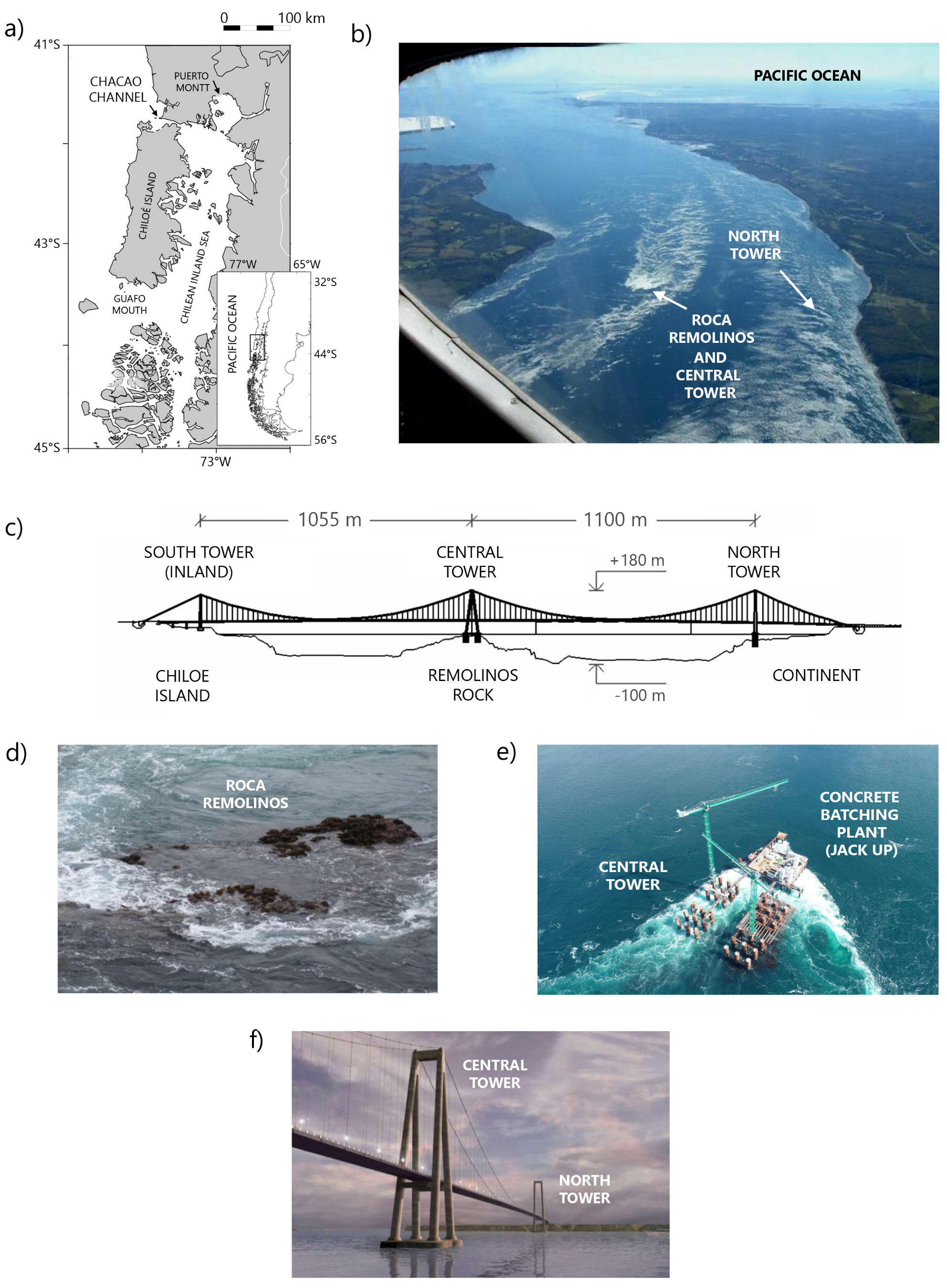
Figure 1. (a) Map showing Chacao Channel, Chiloé Island and the Chilean Inland Sea. (b) Aerial view of the narrowest section of Chacao Channel during ebb tide. Remolinos Rock generates a turbulent wake (courtesy of Horacio Parrague). (c) A frontal view of the bridge showing the position of Central and North towers. (d) A close view of Remolinos rock. (e) A current view of bridge piers being mounted over Remolinos rock site. (f) A projected view of the bridge.
Water 15 00296 g001
Figure 2. Top view geometry and dimensions, in m, of (a) North Tower (NT) and (b) Central Tower (CT) of Chacao bridge (adapted from [29]). NT is made up of two groups of piles, each having 9 cylindrical piles with diameters of D = 2.5 m. CT is a larger structure made up of four groups of piles, each formed by 9 piles of the same diameter. NT and CT occupy areas of 50 × 21 m2 and 59 × 51 m2, respectively. The distance between neighbouring piles is s = 7.5 m, measured from their respective vertical axes. Dashed lines show profiles where speed and shear stress are estimated. Points in red (green): locations where the velocity V ( t ) was estimated for flood (ebb) tide scenario. Points in black: locations for estimating V ( t ) in both scenarios. (c) Definition of a reference frame for the estimation of the approximating flow velocities V ( t ) and the shear stress τ w acting around the piles. (d) Front view of CT site.
Water 15 00296 g002
Figure 3. (a) Definition of the modelling domain at the CT. (b) Definition of boundaries of the numerical domain. (c,d) show a views of the refined mesh used for numerical modelling. Figures adapted from [29].
Water 15 00296 g003
Figure 4. (a) A front view of RETA apparatus [38]. (b) A view of some of the samples and the involved dimensions. Taps at both extremes were also indicated (arrows in red). (c,d) Some samples of Remolinos rock after an erosion test. (e) A view of a sample from NT after an erosion test (figures extracted from [28]).
Water 15 00296 g004
Figure 5. Consecutive steps of rock scour for a turbulent flow: (a) jacking, (b) dislodgement and (c) displacement. Schematic presentation of joint sets for a rock specimen, (d) a rock with 1 joint plane and (e) 3 joint planes, pointed in red circles. Figures adapted from [22,24].
Water 15 00296 g005
Figure 6. Velocity fields at −6 m LAT in the North Tower site for the flood-tide scenario in the (a) no-project condition and (b), with the future assemble of 18 piles. Similar results for the ebb-tide scenario in the (c) no-project condition and (d) with the piles’ structure. Arrows show the local flow direction, black circles the location of each pile and black regions represent seafloor located above −6 m LAT.
Water 15 00296 g006
Figure 7. Side views of velocity fields at a vertical plane (A) coinciding with the southern-most line of piles in the North Tower site for the flood-tide (a,b) and ebb tide- scenarios (c,d) in the no-project condition and with the structure, respectively. Similar results at a vertical plane (B) between the southern-most and the immediate interior lines of piles for the flood-tide (e,f) and ebb tide- scenarios (g,h) in the no-project condition and with the structure, respectively. Arrows show the local flow direction and black lines delineate the structure’s profile.
Water 15 00296 g007
Figure 8. Iso-contours plots of shear stress τ (measured in Pa) around the piles of North Tower for (a) flood-tide and (b) ebb-tide scenarios. High intensity shear stress is shown in yellow, and low intensity in blue. For simplicity, only results for the front and rear rows of the tower were shown. Figures adapted from [29].
Water 15 00296 g008
Figure 9. Frequency distribution of τ w ( t ) for pile A1, obtained for t > t * (upper left pier in Figure 2a) of the NT for (a) the flood-tide (b) and the ebb-tide scenarios. The cumulative frequency curve (in red) is also included. Distribution of τ λ versus the central angle θ (Figure 2c) for (c) the flood-tide (d) and the ebb-tide scenarios. Minimum, maximum and the average of this parameter are shown for reference. Figures adapted from [29].
Water 15 00296 g009
Figure 10. (a) Erosion curves Z ( t ) obtained by considering different erosion rates, r ˙ m i n , r ˙ a v e , r ˙ m a x , for one of the piles of NT (pile A6). The erosion depth Z s was indicated for reference. (b) Parameter Z m a x involved in Equation (19) versus mean flow velocity V at each pile ( V is the velocity obtained from OpenFoam). The fitting curve is given by Equation (21). (c) Cumulated frequency distribution of Z s for its minimum and maximum range of values. Some referential points were included as a guide to the eye. Figures adapted from [29].
Water 15 00296 g010
Figure 11. Velocity fields at −4 m LAT in the Central Tower site for (a) the flood-tide scenario in the no-project condition and (b), with the future assemble of 36 piles. Similar results for (c) the ebb-tide scenario in the no-project condition and (d) with the piles’ structure. Arrows show the local flow direction, black circles the location of each pile, black regions represent seafloor located above −4 m LAT and white regions areas where the water level is below −4 m LAT. Figures adapted from [29].
Water 15 00296 g011
Figure 12. Side views of velocity fields at a vertical plane (A) coinciding with the southern-most line of piles in the CT site for the flood-tide (a,b) and ebb tide- scenarios (c,d) in the no-project condition and with the structure, respectively. Similar results at a vertical plane (B) between the southern-most and the immediate interior lines of piles for the flood-tide (e,f) and ebb tide- scenarios (g,h) in the no-project condition and with the structure, respectively. Arrows show the local flow direction and black lines delineate the structure’s profile. Figures adapted from [29].
Water 15 00296 g012
Figure 13. Frequency distribution of τ w ( t ) for pile A1, for t [ t * , Δ T ] for pile A1 (upper left pier in Figure 2b) of the CT site for (a) the flood-tide scenario (b) and the ebb-tide scenario. The cumulative frequency curve (in red) is also included. Distribution of τ λ versus the central angle θ (Figure 2c) for for (c) the flood-tide scenario (d) and the ebb-tide scenario. Minimum, maximum and the average of this parameter are shown for reference. Figures adapted from [29].
Water 15 00296 g013
Figure 14. Erodibility at CT site. (a) Distribution of P A / P versus V obtained for minimum, maximum and average shear stress ( τ λ m i n , τ λ a v e , τ λ m a x ). The fit corresponds to Equation (21) for averaged data. A critical “scour” velocity V c = 6.6 m/s was included. (b) Cumulated frequency distribution curves obtained for the ratio P A / P for the same conditions. The erosion risk region ( P A / P 1 ) was shown for reference (box in light green).
Water 15 00296 g014
Figure 15. Distribution of parameter ξ for flood-tide and ebb-tides acting at North Tower site, versus (a) the mean Froude ( F r ) number and (b), the relative depth h / D , where h is the mean flow depth around each pier and D the diameter. The horizontal dashed line corresponds to ξ = 1.
Water 15 00296 g015
Table 1. Simulation parameters adopted in OpenFOAM for both towers.
DescriptionItemCentral Tower (CT)North Tower (NT)
Grid StatsMesh softwareSnappyHexMeshSnappyHexMesh
# of Points2,020,2832,171,168
# of Faces5,109,5345,447,175
Internal4,722,2334,977,149
# of Cells1,565,7371,656,988
Skewness (max)3.724.13
Solver/NumericsInternal solverInterFoamInterFoam
(incompressible/biphase)(incompressible/biphase)
Continuity link with pressurePIMPLE algorithmPIMPLE algorithm
Interpolation advection scheme (U)Linear UpwindLinear Upwind
Interpolation advection scheme ( α )Van LeerVan Leer
Linear solvers for PrghGAMG /PCGGAMG /PCG
(w/preconditioner)(w/preconditioner)
Linear solvers for U / k SmoothSolverSmoothSolver
GaussSeidelGaussSeidel
Turbulence TreatmentPrimary aproximationRANSRANS
Turbulence closure modelkOmegaSSTkOmegaSST
Boundary Conditions Wave2FoamWave2Foam
w/relaxation zonew/relaxation zone
Initial ConditionsVelocity (U)00
Pressure (P)Hydrostatic P. by sea lvl.Hydrostatic P. by sea lvl.
α Air-water by cell z coord.Air-water by cell z coord.
Table 2. Boundary conditions at NW and SE sides of the numerical domain of both sites obtained from a large-scale numerical model built in a Mike21, using the non-linear shallow water equations for extreme tidal ranges [29]. (1) A negative value denotes a free surface under the sea level ( = 0 m.a.s.l.). (2) A negative value denotes a flow direction opposite to flood tide.
VelocityFree Surface
(m/s)(m.a.s.l.)
SiteScenarioNWSENWSE
North TowerFlood-Tide2.382.27−2.32 (1)−2.32
North TowerEbb-Tide−2.69 (2)−2.661.601.63
Central TowerFlood-Tide3.602.48−1.81−1.87
Central TowerEbb-Tide−3.25−2.871.701.94
Table 3. Rate erosion r ˙ obtained from RETA tests for samples extracted from North Tower (samples: TN1, TN2 and TN3).
SampleRunT Δ t Δ m τ r ˙
(N·mm)(hr.)(g)(Pa)(mm/year)
TN111513.21.4920.8818.10
21535.52.1720.889.80
3306.20.0041.760.00
43019.30.6841.765.60
5456.00.3862.6310.20
6606.00.3883.5110.20
TN214017.31.8778.4732.74
23026.00.7958.869.22
32034.00.5839.245.18
41511.00.2329.436.35
55022.01.1198.0915.31
TN31220.03.185.7732.60
2207.30.4952.4613.90
3308.00.6278.6915.90
Min. 6.0 5.770.00
Max. 35.5 98.0932.74
Average 16.6 50.8913.22
Table 4. Rate erosion r ˙ obtained from RETA tests for samples extracted from CT (samples: RR1, RR2, RR3, RR4 and RR5).
SampleRunT Δ t Δ m τ r ˙
(N·mm)(hr.)(g)(Pa)(mm/year)
RR111530.00.0021.010.00
22566.50.0035.020.00
35099.00.0070.050.00
RR214014.02.16113.52402.97
22021.00.2556.7646.64
31072.00.3528.3865.30
43048.00.4685.1485.82
RR314014.02.16113.52402.97
22001.40.02294.733.90
32501.10.01368.411.90
RR4150137.00.0099.440.00
RR5160149.50.0090.630.00
Min. 1.1 21.00.00
Max. 149.5 368.4402.97
Average 54.5 114.784.12
Table 5. Erodibility index K calculated for Remolinos rock. The parameters included in the table were already described in the text.
SymbolDescriptionValueComment
M s Mass strength number8.39It considers information extracted
from geotechnical test (in MPa)
K b Particle size number19.04
J x Average joint spacing (along x)1.00It considers a mean spacing
= D / 2 , where D = 6 m
J y Average joint spacing (along y)1.00
J z Average joint spacing (along z)1.00
dMean diameter of blocs1.00Measured in (m)
J c = 3 ( 1 + ( J x J y J z ) 0.33 ) 6.00
R Q D Rock quality95.20This parameter usually ranges
from 0 to 100
J n Joint set number5.00Considering very fractured
rock, suggested by [25,27]
K d Shear strength number0.10
J r Joint roughness1.00It assumes that joints remain
open during rock’s scour
J a Joint alteration10.00It considers rock void spaces
filled with strongly consolidated
cohesive materials, with or without
crushed rocks
J s Ground structure number0.73Value suggested by [27]
KErodibility index11.66
PThreshold Power = K 0.75 6.31kWatt·m−2
Table 6. Range of scour depth Z s and final scour depth value Z D adopted at NT and CT. (*) Estimated considering Equations (25) and (26).
SiteMethodRisk ofScourSafety Z D ( * ) Refs.
Erosion Z s (m)Factor ( f s )(m)
North TowerSRICOSHigh0.67–1.821.442.82 [48,63]
Central TowerEIMVery low0.01–0.631.671.63 [21,22,25]
Disclaimer/Publisher’s Note: The statements, opinions and data contained in all publications are solely those of the individual author(s) and contributor(s) and not of MDPI and/or the editor(s). MDPI and/or the editor(s) disclaim responsibility for any injury to people or property resulting from any ideas, methods, instructions or products referred to in the content.