
Enhanced Groundwater Protection and Management Using Gravity and Geoelectrical Data (Valls Basin, Spain)

 ,
,  ,
,  , , and
Abstract
:1. Introduction
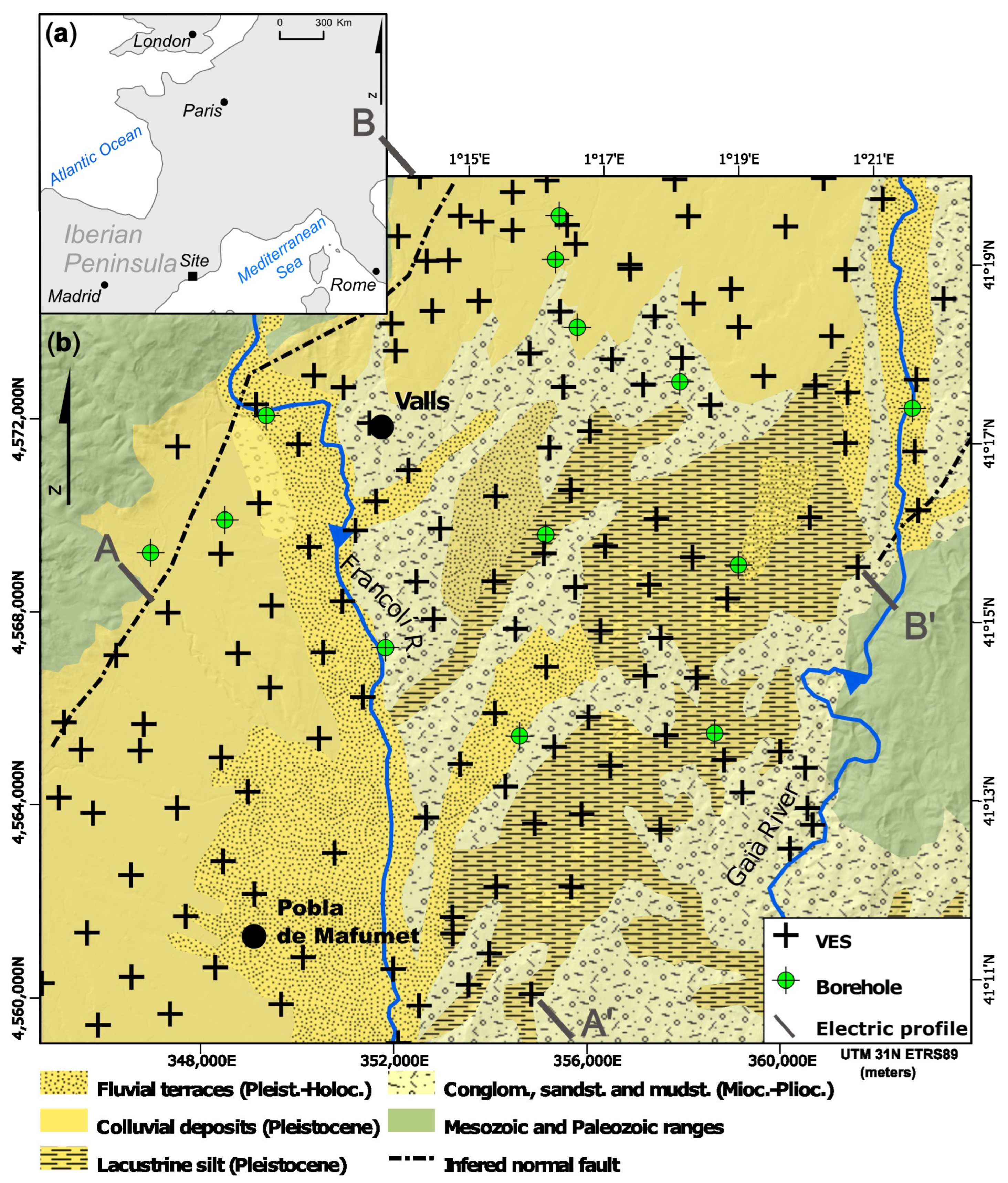
2. Studied Zone
3. Materials and Methods
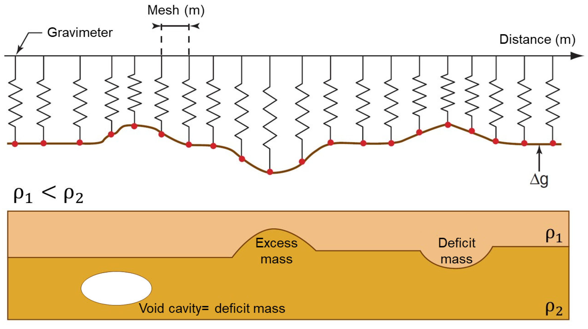
3.1. Gravity Survey
3.2. Geoelectrical Survey
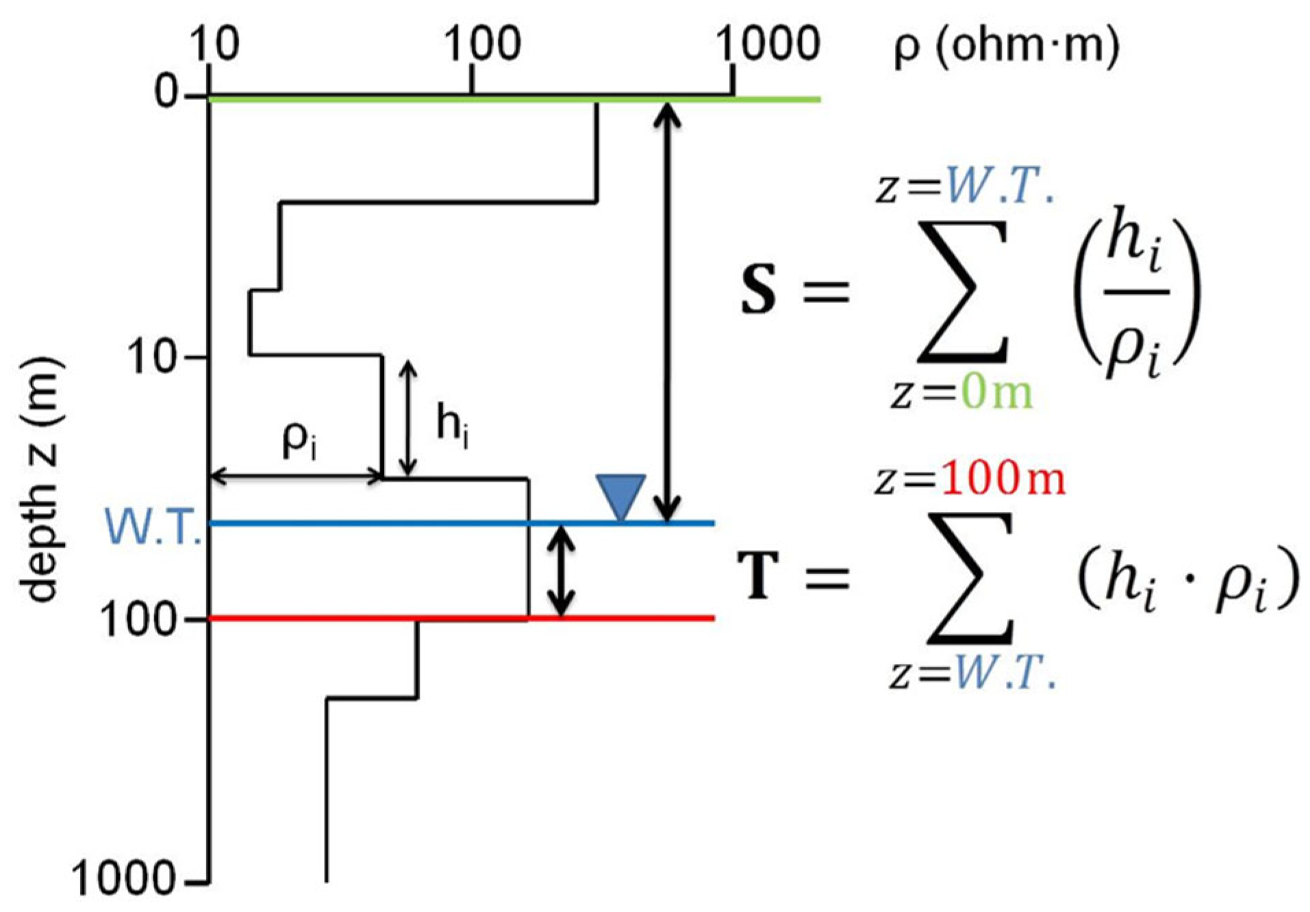
3.3. Dar Zarrouk Parameters
3.4. Vulnerability Assessment
4. Results and Discussion
4.1. Gravity Survey
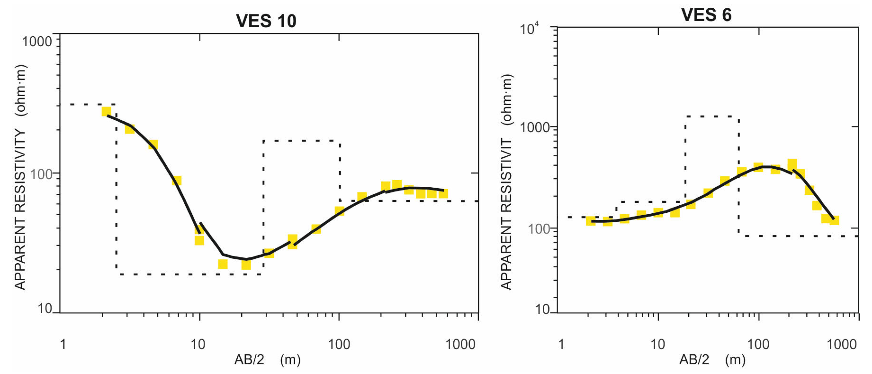
4.2. Geoelectrical Survey
4.3. Hydraulic Transmissivity
4.4. Aquifer Vulnerability
5. Conclusions
- The specific treatment carried out on data from geophysical data gravity stations and vertical electric soundings and their reinterpretation, supported by the available well data, has also allowed the hydraulic characteristics of the aquifer system and its vulnerability to contamination through the unsaturated zone to be characterised on a regional scale. Geophysical methods have proved useful in this application, providing valuable information in a non-destructive way, i.e., without the need to drill new boreholes in the ground that could act as preferential pathways for pollutants into the aquifer.
- The results of the interpretation of the VES curves are consistent with the available lithological information on the subsoil and have a better spatial distribution in the study area than the lithological information. Thus, it has been identified that the most favourable areas for the exploitation of groundwater resources are located in the less sinuous sections of the Francolí and Gaià rivers and at the west outskirts of Valls.
- The longitudinal electrical conductance map (Dar Zarrouk S-parameter) effectively shows the protection that exists against groundwater contamination due to the existence of the low vertical permeability of the unsaturated zone, i.e., the uppermost layers between the ground surface and the piezometric level. S values above 0.5 Siemens indicate areas where the aquifer system is more protected, while S values below 0.5 Siemens indicate areas with a higher risk of groundwater contamination, either at a particular point or diffused.
- The correlation between the longitudinal electrical conductance (parameter S of Dar Zarrouk) and the resistance of water to vertical flow through the unsaturated zone was used as a quantitative index in the AVI (Aquifer Vulnerability Index) method to evaluate the vulnerability of groundwater pollution and has made it possible to determine the areas most susceptible to pollution according to the transit time from its infiltration on the surface to reach the aquifer. In the Valls Basin, the most vulnerable areas, with transit times of less than 3 years, are located mainly in the southern part of the study area, while the best-protected areas, with transit times of more than 9 years, are located in the central and northern sectors.
Supplementary Materials
Author Contributions
Funding
Data Availability Statement
Acknowledgments
Conflicts of Interest
References
- European Parliament and Council Comission Directive 2014/101/EU of 30 October 2014 Amending Directive 2000/60/EC Establishing a Framework for Community Action in the Field of Water Policy. Available online: https://eur-lex.europa.eu/legal-content/EN/TXT/HTML/?uri=CELEX:32014L0101 (accessed on 13 October 2023).
- European Parliament and Council Directive 2006/118/EC of 12 December 2006 on the Protection of Groundwater Against Pollution and Deterioration. Available online: https://eur-lex.europa.eu/legal-content/EN/TXT/HTML/?uri=CELEX:02006L0118-20140711 (accessed on 10 October 2023).
- Duijvenbooden, W.; Waegeningh, H.G.; Foster, S.S.D. Vulnerability of soil and groundwater to pollutants. In Proceedings of the Fundamental Concepts in Aquifer Vulnerability, Pollution Risk and Protection Strategy, Noordwijk Aan Zee, The Netherlands, 30 March 1987; TNO Committee on Hydrological Research: Noordwijk aan Zee, The Netherlands, 1987; p. 1143. [Google Scholar]
- Voigt, H.; Heinkele, T.; Jahnke, C.; Wolter, R. Characterization of groundwater vulnerability to fulfill requirements of the water framework directive of the European. Geofísica Int. 2004, 43, 567–574. [Google Scholar] [CrossRef]
- Galperin, Y.; Odencrantz, J.E. Biodegradation dynamics disparity between n-alkanes and polycyclic aromatic hydrocarbons in the vadose zone: A critical review. Remediat. J. 2022, 32, 119–128. [Google Scholar] [CrossRef]
- Feng, S.-J.; Zhu, Z.-W.; Chen, H.-X.; Chen, Z.-L.; Ding, X.-H. Two-dimensional analytical solution for subsurface volatile organic compounds vapor diffusion from a point source in layered unsaturated zone. J. Contam. Hydrol. 2021, 243, 103916. [Google Scholar] [CrossRef]
- Aind, D.A.; Malakar, P.; Sarkar, S.; Mukherjee, A. Controls on Groundwater Fluoride Contamination in Eastern Parts of India: Insights from Unsaturated Zone Fluoride Profiles and AI-Based Modeling. Water 2022, 14, 3220. [Google Scholar] [CrossRef]
- Gogu, R.C.; Dassargues, A. Current trends and future challenges in groundwater vulnerability assessment using overlay and index methods. Environ. Geol. 2000, 39, 549–559. [Google Scholar] [CrossRef]
- Vrba, J.; Zaporozec, A. Guidebook on Mapping Groundwater Vulnerability. International Contributions to Hydrogeology; International Association of Hydrogeologists: Hannover, Germany, 1994; ISBN 978-3922705970. [Google Scholar]
- Hashimoto, T.; Stedinger, J.R.; Loucks, D.P. Reliability, resiliency, and vulnerability criteria for water resource system performance evaluation. Water Resour. Res. 1982, 18, 14–20. [Google Scholar] [CrossRef]
- Casas, A.; Himi, M.; Díaz, Y.; Pinto, V.; Font, X.; Tapias, J.C. Assessing aquifer vulnerability to pollutants by electrical resistivity tomography (ERT) at a nitrate vulnerable zone in NE Spain. Environ. Geol. 2008, 54, 515–520. [Google Scholar] [CrossRef]
- Aller, L.; Bennett, T.; Lehr, J.H.; Petty, R.J.; Hackett, G. NWWA/EPA-600/2-87-035. DRASTIC: A Standardized Method for Evaluating Ground Water Pollution Potential Using Hydrogeologic Settings. EPA: Washington, DC, USA, 1987; p. 455. [Google Scholar]
- Civita, M.; De Maio, M. SINTACS: Un Sistema Parametrico per la Valutazione E la Cartografia delle Vulnerabilità Degli Acquiferi All’Inquinamento. Metodologia e Automatizzazione; Pitagora Editrice: Bologna, Italy, 1997; ISBN 9788837108991. [Google Scholar]
- Chachadi, A.G.; Lobo-Ferreira, J.-P. Sea water intrusion vulnerability mapping of aquifers using the GALDIT method. In Proceedings of the UNESCO-IHP Workshop on Modelling in Hydrogeology, Chennai, India, 3 December 2001; Volume 4, pp. 7–9. [Google Scholar]
- Khosravi, K.; Bordbar, M.; Paryani, S.; Saco, P.M.; Kazakis, N. New hybrid-based approach for improving the accuracy of coastal aquifer vulnerability assessment maps. Sci. Total Environ. 2021, 767, 145416. [Google Scholar] [CrossRef]
- Andersen, L.J.; Gosk, E. Applicability of vulnerability maps. Environ. Geol. Water Sci. 1989, 13, 39–43. [Google Scholar] [CrossRef]
- Kumar, S.; Thirumalaivasan, D.; Radhakrishnan, N.; Mathew, S. Groundwater vulnerability assessment using SINTACS model. Geomat. Nat. Hazards Risk 2013, 4, 339–354. [Google Scholar] [CrossRef]
- Jury, W.A.; Horton, R. Soil Physics, 6th ed.; John Wiley & Sons, Inc.: New York, NY, USA, 2004; ISBN 978-0-471-05965-3. [Google Scholar]
- Henriet, J.P. Direct applications of the Dar Zarrouk parameters in ground water surveys. Geophys. Prospect. 1976, 24, 344–353. [Google Scholar] [CrossRef]
- Kirsch, R. Groundwater protection: Vulnerability of aquifers. In Groundwater Geophysics. A Tool for Hydrogeology; Kirsch, R., Ed.; Springer: Berlin, Germany, 2009; pp. 511–525. ISBN 978-3-540-88404-0. [Google Scholar]
- Kirsch, R.; Sengpiel, K.-P.; Voss, W. The use of electrical conductivity mapping in the definition of an aquifer vulnerability index. Near Surf. Geophys. 2003, 1, 13–19. [Google Scholar] [CrossRef]
- Mohammadi, K.; Niknam, R.; Majd, V.J. Aquifer vulnerability assessment using GIS and fuzzy system: A case study in Tehran–Karaj aquifer, Iran. Environ. Geol. 2009, 58, 437–446. [Google Scholar] [CrossRef]
- George, N.J. Integrating hydrogeological and second-order geo-electric indices in groundwater vulnerability mapping: A case study of alluvial environments. Appl. Water Sci. 2021, 11, 1–12. [Google Scholar] [CrossRef]
- Bernardo, B.; Candeias, C.; Rocha, F. Integration of Electrical Resistivity and Modified DRASTIC Model to Assess Groundwater Vulnerability in the Surrounding Area of Hulene-B Waste Dump, Maputo, Mozambique. Water 2022, 14, 1746. [Google Scholar] [CrossRef]
- Niwas, S.; Singhal, D.C. Estimation of aquifer transmissivity from Dar-Zarrouk parameters in porous media. J. Hydrol. 1981, 50, 393–399. [Google Scholar] [CrossRef]
- Soupios, P.; Kouli, M.; Vallianatos, F.; Vafidis, A.; Stavroulakis, G. Estimation of aquifer hydraulic parameters from surficial geophysical methods: A case study of Keritis Basin in Chania (Crete–Greece). J. Hydrol. 2007, 338, 122–131. [Google Scholar] [CrossRef]
- Batte, A.G.; Barifaijo, E.; Kiberu, J.M.; Kawule, W.; Muwanga, A.; Owor, M.; Kisekulo, J. Correlation of Geoelectric Data with Aquifer Parameters to Delineate the Groundwater Potential of Hard rock Terrain in Central Uganda. Pure Appl. Geophys. 2010, 167, 1549–1559. [Google Scholar] [CrossRef]
- Sendrós, A.; Himi, M.; Lovera, R.; Rivero, L.; Garcia-Artigas, R.; Urruela, A.; Casas, A. Geophysical Characterization of Hydraulic Properties around a Managed Aquifer Recharge System over the Llobregat River Alluvial Aquifer (Barcelona Metropolitan Area). Water 2020, 12, 3455. [Google Scholar] [CrossRef]
- Cobourn, K.M.; Elbakidze, L.; Ghosh, S. Chapter 3.1.2-Conjunctive Water Management in Hydraulically Connected Regions in the Western United States; Ziolkowska, J.R., Peterson, J.M.B.T.-C., Eds.; Elsevier: Amsterdam, The Netherlands, 2017; pp. 278–297. ISBN 978-0-12-803237-4. [Google Scholar]
- ICGC. Alt Camp. Mapa Geològic Comarcal de Catalunya 1:50 000; Institut Cartogràfic i Geològic de Catalunya: Barcelona, Spain, 2005. [Google Scholar]
- ACA. Massa D’Aigua 25. Alt Camp. Fitxa de Caracterització, anàlisi de Pressions, Impactes I anàlisi del Risc D’Incompliment; Agència Catalana de l’Aigua. Generalitat de Catalunya: Barcelona, Spain, 2004. [Google Scholar]
- López-Geta, J.A.; Ramos, G.; Fernández, M.L.; Peinado, T.; Rodríguez, L.; Torrens, J.; Solesillo, J.; Alfonso, P.L.; Fernández, G.; Batlle, A. Estudio de Los Recursos Hídricos Subterráneos del Sistema Hidrogeológico 74. Camp de Tarragona, 1st ed.; Instituto Geológico y Minero de España: Madrid, Spain, 1986; ISBN 84-7474-347-8. [Google Scholar]
- ACA Catalonia Water Quantity Control Data. Agència Catalana de l’Aigua. Departament de Territori i Sosteniblitat. Generalitat de Catalunya. Available online: http://aca-web.gencat.cat/sdim21/ (accessed on 5 October 2023).
- ACA. Zones Vulnerables a la Contaminació per Nitrats Procedents de Fonts Agràries. Fitxes de Les Zones Vulnerables; Agència Catalana de l’Aigua. Generalitat de Catalunya: Barcelona, Spain, 2022. [Google Scholar]
- Telford, W.M.; Geldart, L.P.; Sheriff, R.E. Applied Geophysics, 2nd ed.; Cambridge University Press: Cambridge, UK, 1990; ISBN 9780521339384. [Google Scholar]
- LCPC. Détection de Cavités Souterraines Par Méthodes Géophysiques; Laboratoire Central des Ponts et Chaussés. Institut Français des Sciences et Techniques des Réseaux, de l’Aménagement et des Transport: Marne la Vallée, France, 2004; ISBN 2-7208-0374-X. [Google Scholar]
- LaFehr, T.R. Standardization in gravity reduction. Geophysics 1991, 56, 1170–1178. [Google Scholar] [CrossRef]
- Griffiths, D.H.; Barker, R.D. Two-dimensional resistivity imaging and modelling in areas of complex geology. J. Appl. Geophys. 1993, 29, 211–226. [Google Scholar] [CrossRef]
- Cimino, A.; Cosentino, C.; Oieni, A.; Tranchina, L. A geophysical and geochemical approach for seawater intrusion assessment in the Acquedolci coastal aquifer (Northern Sicily). Environ. Geol. 2008, 55, 1473–1482. [Google Scholar] [CrossRef]
- McInnis, D.; Silliman, S.; Boukari, M.; Yalo, N.; Orou-Pete, S.; Fertenbaugh, C.; Sarre, K.; Fayomi, H. Combined application of electrical resistivity and shallow groundwater sampling to assess salinity in a shallow coastal aquifer in Benin, West Africa. J. Hydrol. 2013, 505, 335–345. [Google Scholar] [CrossRef]
- Canzoneri, A.; Capizzi, P.; Martorana, R.; Albano, L.; Bonfardeci, A.; Costa, N.; Favara, R. Geophysical Constraints to Reconstructing the Geometry of a Shallow Groundwater Body in Caronia (Sicily). Water 2023, 15, 3206. [Google Scholar] [CrossRef]
- Orellana, E. Prospección Geoeléctrica en Corriente Continua, 2nd ed.; Thomson Paraninfo: Madrid, Spain, 1982; ISBN 9788428311533. [Google Scholar]
- Interpex. RESIX PLUS v2.53. User Manual Resitivity Data Interpretation Software; Interpex Limited: Golden, CO, USA, 1993. [Google Scholar]
- Inman, J.R. Resistivity inversion with ridge regression. Geophysics 1975, 40, 798–817. [Google Scholar] [CrossRef]
- Maillet, R. The fundamental equations of electrical prospecting. Geophysics 1947, 12, 529–556. [Google Scholar] [CrossRef]
- Edwards, L.S. A modified pseudosection for resistivity and IP. Geophysics 1977, 42, 1020–1036. [Google Scholar] [CrossRef]
- ACA Catalonia Water Quality Control Data. Agència Catalana de l’Aigua. Departament de Territori i Sosteniblitat. Generalitat de Catalunya. Available online: http://aca-web.gencat.cat/sdim21/ (accessed on 2 November 2021).
- Davis, J.C. Statistics and Data Analysis in Geology, 3rd ed.; Wiley: New York, NY, USA, 2002; ISBN 978-0-471-17275-8. [Google Scholar]
- Sendrós, A.; Díaz, Y.; Himi, M.; Tapias, J.C.; Rivero, L.; Font, X.; Casas, A. An evaluation of aquifer vulnerability in two nitrate sensitive areas of Catalonia (NE Spain) based on electrical resistivity methods. Environ. Earth Sci. 2014, 71, 77–84. [Google Scholar] [CrossRef]
- Stempvoort, D.; Van Ewert, L.; Wassenaar, L. Aquifer Vulnerability Index: A GIS-compatible method for groundwater vulnerability mapping. Can. Water Resour. J. 1993, 18, 25–37. [Google Scholar] [CrossRef]
- Kalinski, R.J.; Kelly, W.E.; Bogardi, I.; Pesti, G. Electrical resistivity measurements to estimate travel times through unsaturated ground water protective layers. J. Appl. Geophys. 1993, 30, 161–173. [Google Scholar] [CrossRef]
- Agarwal, B.N.P. Direct gravity interpretation of sedimentary basin using digital computer—Part I. Pure Appl. Geophys. 1971, 86, 5–12. [Google Scholar] [CrossRef]
- Casas, A.; Torné, M.; Banda, E. Mapa Gravimètric de Catalunya 1:500.000; Servei Geològic de Catalunya. Departament de Política Territorial i Obres Públiques: Barcelona, Spain, 1986; ISBN 978-84-393-0740-2. [Google Scholar]
- Guimerà, J.J. Estudi estructural de L’Enllaç Entre la Serralada Ibèrica i la Serralada Costanera Catalana; Universitat de Barcelona: Barcelona, Spain, 1988. [Google Scholar]
- Bovachev, A.A.; Modin, I.N.; Shevnin, V.A. 1D Interpretation of VES profile software (IPI2Win v3.0.1); Moscow State University, Department of Geophysics: Moscow, Russia, 2011. [Google Scholar]
- Smith, W.H.F.; Wessel, P. Gridding with continuous curvature splines in tension. Geophysics 1990, 55, 293–305. [Google Scholar] [CrossRef]
- MPRCMD. Real Decreto 47/2022, de 18 de Enero, Sobre Protección de Las Aguas Contra la Contaminación Difusa Producida Por Los Nitratos Procedentes de Fuentes Agrarias; Ministerio de la Presidencia, Relaciones con las Cortes y Memoria Democrática. Gobierno de España: Madrid, Spain, 2022. [Google Scholar]
- Alabi, O.O.; Ojo, A.O.; Akinpelu, D.F. Geophysical Investigation for Groundwater Potential and Aquifer Protective Capacity around Osun State University (UNIOSUN) College of Health Sciences. Am. J. Water Resour. 2016, 4, 137–143. [Google Scholar] [CrossRef]
- Sendrós, A.; Himi, M.; Estévez, E.; Lovera, R.; Palacios-Diaz, M.P.; Tapias, J.C.; Cabrera, M.C.; Pérez-Torrado, F.J.; Casas, A. Hydrogeophysical Assessment of the Critical Zone below a Golf Course Irrigated with Reclaimed Water close to Volcanic Caldera. Water 2021, 13, 2400. [Google Scholar] [CrossRef]
- Zaporozec, A.; Miller, J.C. Ground-Water Pollution; United Nations Educational, Scientific and Cultural Organization: Paris, France, 2000. [Google Scholar]
- Debernardi, L.; De Luca, D.A.; Lasagna, M. Correlation between nitrate concentration in groundwater and parameters affecting aquifer intrinsic vulnerability. Environ. Geol. 2008, 55, 539–558. [Google Scholar] [CrossRef]


| Pollutant Transit Time (years) | Vulnerability |
|---|---|
| 0–2 | Very high |
| 3–8 | Medium-high |
| >9 | Low |
Disclaimer/Publisher’s Note: The statements, opinions and data contained in all publications are solely those of the individual author(s) and contributor(s) and not of MDPI and/or the editor(s). MDPI and/or the editor(s) disclaim responsibility for any injury to people or property resulting from any ideas, methods, instructions or products referred to in the content. |
© 2023 by the authors. Licensee MDPI, Basel, Switzerland. This article is an open access article distributed under the terms and conditions of the Creative Commons Attribution (CC BY) license (https://creativecommons.org/licenses/by/4.0/).
Share and Cite
Sendrós, A.; Himi, M.; Rivero, L.; Lovera, R.; Urruela, A.; Tapias, J.C.; Casas, A. Enhanced Groundwater Protection and Management Using Gravity and Geoelectrical Data (Valls Basin, Spain). Water 2023, 15, 4130. https://doi.org/10.3390/w15234130
Sendrós A, Himi M, Rivero L, Lovera R, Urruela A, Tapias JC, Casas A. Enhanced Groundwater Protection and Management Using Gravity and Geoelectrical Data (Valls Basin, Spain). Water. 2023; 15(23):4130. https://doi.org/10.3390/w15234130
Chicago/Turabian StyleSendrós, Alex, Mahjoub Himi, Lluís Rivero, Raúl Lovera, Aritz Urruela, Josefina C. Tapias, and Albert Casas. 2023. "Enhanced Groundwater Protection and Management Using Gravity and Geoelectrical Data (Valls Basin, Spain)" Water 15, no. 23: 4130. https://doi.org/10.3390/w15234130
APA StyleSendrós, A., Himi, M., Rivero, L., Lovera, R., Urruela, A., Tapias, J. C., & Casas, A. (2023). Enhanced Groundwater Protection and Management Using Gravity and Geoelectrical Data (Valls Basin, Spain). Water, 15(23), 4130. https://doi.org/10.3390/w15234130