Article

CFD as a Decision Tool for Pumped Storage Hydropower Plant Flow Measurement Method

1
Faculty of Civil Engineering, Czech Technical University in Prague, Thákurova 2077/7, 166 29 Praha, Czech Republic
2
Faculty of Mechanical Engineering, J. E. Purkyně University, Pasteurova 1, 400 01 Ústí nad Labem, Czech Republic
3
ČEZ, a.s., Duhová 2/1444, Praha 4, 140 53 Prague, Czech Republic
*
Author to whom correspondence should be addressed.
Water 2023, 15(4), 779; https://doi.org/10.3390/w15040779
Submission received: 30 December 2022 / Revised: 13 February 2023 / Accepted: 14 February 2023 / Published: 16 February 2023
(This article belongs to the Special Issue Pumped-Storage Hydropower: Flexible Giants for the Energy Transition)

Abstract

:
Suitable and accurate flow measurement in pumped storage hydropower plants (PSP) is a challenging task due to the entirely different hydraulic behaviour of the penstock. This study presents a novel approach to choosing a suitable flow measurement method and position. The focus is on the flow measurement in a specific short penstock of the largest peak-load hydropower plant, Orlík, after its transformation to a PSP. Our approach is based on three main pillars: numerical modelling of fluid flow (ANSYS CFX), standards, and scientific literature. First, the steady-state numerical model output for the current state is compared to historical measurements of point velocities using current meters and measured hydraulic losses in the penstock. Subsequently, for the planned conversion to the reversible Francis turbine, including shape modifications of the flow paths, a steady numerical simulation of the flow in the penstock was performed in both turbine and pump modes. By analysing the resulting pressure and velocity fields and comparing them to standards and scientific literature, the values of the uncertainty in the flow measurement were calculated. The outcome is a straightforward evaluation and comparison of three main flow measurement methods: current meter, pressure–time, and ultrasonic transit time.

1. Introduction

As the share of renewable resources (RES) expands, the demand for maintaining the electricity grid’s stability increases. The main renewable sources—sun, wind, and partly water—are highly dependent on the behaviour of weather and climate and therefore show great performance unevenness over time [1]. One of the possibilities is the construction of backup power plants. Unfortunately, these backup power plants are often thermal, despite ongoing efforts to incorporate RES sources as an operating reserve [2]. The most suitable solution is energy storage in other forms—potential mechanical, thermal, etc. One of the oldest types of energy storage is flywheels [3], which are commonly used for accumulating kinetic energy in turbines and electric motors in automobiles [4]. Another type is electric battery storage, which has recently experienced a significant increase. An example is the planned construction of a 200 MW/820 MWh storage facility connected to the Zarniowec PVE in Poland, which should be operational in 2030 [5]. Because large battery storage facilities are made up of lithium batteries, it is essential to highlight the environmental disadvantage of lithium mining, which, with the increasing demand for batteries for electric vehicles, can pose a significant ecological problem [6]. Another attractive method is to use hydrogen as an energy carrier. However, most hydrogen is produced from fossil fuels. Only 4% is produced by the electrolysis of water. According to the IRENA report [7], roughly only 1% of hydrogen was produced using renewable sources. The main reason is the high price of green hydrogen production. An overview of most energy storage methods and technologies can be found, for example, in Olabi et al. [8].
Despite the rapid development of various methods for energy storage, indicating the importance of this problem, by 2021, 96% of the world’s installed power and 99% of the actual energy was stored in PSPs [9,10]. Although the other types of energy storage mentioned here can be expected to expand significantly, PSPs will remain the dominant player in the field of energy storage. One of the advantages is the relatively overall low cost per produced kWh—e.g., for PSPs with large heads, it can be as low as 0.1 €/kWh in the US [11] to 0.5 €/kWh in Norway [12], which is still several times less than in battery storage systems [13], although the price is still falling [14]. From the point of view of energy storability, price per kWh, and ecological operation, pumped hydro is still the winner.
The construction of new large pumped storage hydro can be problematic, especially in more densely populated Central and Western Europe areas. This is due to the limited number of suitable locations and the resistance of the population, because of so-called NIMBY (“Not in my backyard”) [15], or due to justified concerns due to the location of reservoirs in nature-protected locations. It is possible to build new micro-PSPs, but they are economically disadvantageous if they do not use the existing infrastructure, such as pipe systems, buildings, and reservoirs [16].
For the reasons mentioned above, it is most economically efficient to use locations with large peak-load hydropower plants, ideally with larger heads, where hydropower plants can be transformed into PSPs with a minimum of costs (modification of penstock, replacement of turbines). In the literature, there are not many cases of simple conversion of the classic dam to pumped storage hydro, and most of them require the construction of a second upper reservoir [17].
In this article, we will deal with the Orlík locality transformation to PSP. Orlík dam, with the hydropower plant of the same name, is located on the Vltavská kaskáda—Vltava River Cascade (Figure 1). The Vltava River Cascade is a cascade of nine hydropower plants on the Vltava River built between 1930 and 1992. This system fulfils many functions—flood protection, recreation, water supply, and energy generation. The total installed capacity of the hydroelectric power plants on the cascade is 750 MW, of which 364 MW is installed at the Orlík hydropower plant. Thanks to the deep elbow draft tubes of the Orlík powerplant (approximately 12 m below the minimum tail-water level), it is possible to convert the existing Orlík power plant into a PSP with a lower reservoir Kamýk. The plan is to replace all four Kaplan turbines with Francis turbines, at least one of which will be reversible.
There are now a total of three large PSPs in the Czech Republic—namely Dlouhé Stráně (650 MW), Dalešice (480 MW), and Štěchovice II (45 MW), with a total installed capacity of 1175 MW. With the partial conversion of the Orlík to pumped hydro, it will be increased by another approx. 200 MW.
Although changing the existing use by replacing the turbine is much simpler than building a new PSP, it also entails several problems and risks. The main risk is integrating technology into existing hydraulic flow paths with minimal intervention. For example, these are the risks of forming intake vortices at the inlet to the elbow draft tube in the pump regime. Another problem is the behaviour of tail water during the simultaneous operation of the turbine and the pump (outer hydraulic short circuit). However, this article focuses on the issue of flow measurement in the penstock in the future pump and turbine regime. Due to the very short penstock (circular pipe section only approx. 9 L/D) and the change of use (in addition to the turbine and pump regimes), the performance of a CFD simulation is necessary. Both are used to verify the behaviour of flow in penstock, determine the suitability of the guarantee measurement, and identify the uncertainties of three flow measurement methods: current meter, pressure–time, and ultrasonic method. Especially in the pump regime, fundamental problems are expected with the flow measurement accuracy and, thus, high uncertainties in verifying the efficiency of the supplied turbine technology.

2. Current State

2.1. Peak Load Hydropower Plant Orlík

The Czech largest peak load hydropower plant with an installed capacity of 4 × 91 MW was built on the Orlík dam in 1960 and 1961. Even with a high head of around 70 m, four Kaplan turbines were installed. All four turbines have identical penstocks and intake structures (Figure 2).

2.2. Planned Transformation to PSP

As already mentioned in the introduction, thanks to the system with the lower Kamýk reservoir, it is possible to effectively use the existing infrastructure of Orlík and change the purpose of using the entire power plant to PSP. As already said, the plan is to replace all four Kaplan turbines with Francis turbines, at least one of which will be reversible (Table 1). In addition to the turbine itself, especially for the reversible turbine, suitable partial shape adjustments of the spiral will be made about the larger diameter of the runner and the connection to the new inlet cone, which will be connected to the existing elbow of the draft tube. Other parts of the machinery will be adapted to the new function, but mostly completely replaced, including auxiliary parts.

2.3. CFD Model—Setup and Validation

To objectively assess the suitability and accuracy of individual flow measurement methods, we need to know the velocity and pressure behaviour in the penstock for the turbine and pump regime or both flow directions. For this reason, a CFD numerical model of the current state was created and validated with historical measurements of hydraulic losses and with the velocity field in one profile.

2.3.1. Three-Dimensional (3D) Model

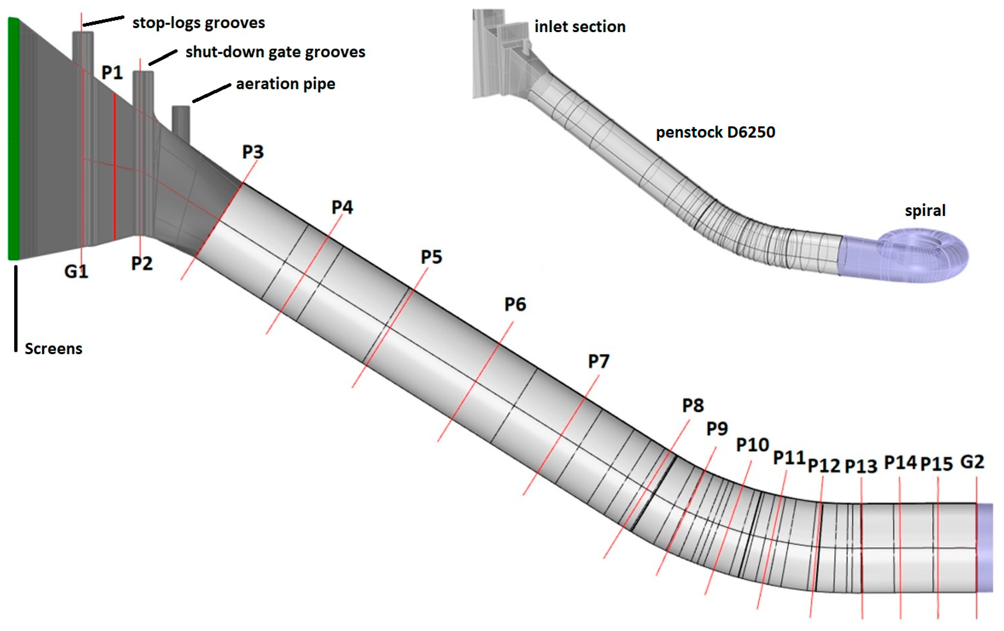
A 3D model (Figure 2) was created from the available drawing documentation, ranging from the section of the Orlík reservoir to the transition of the guide vanes into the runner chamber. The model also includes details such as grooves of stop logs and an emergency shutdown gate or aeration pipe. Great emphasis was placed on the correct modelling of the shape of the transition piece between the rectangular profile and the circular profile of the penstock (in Figure 2—from profile P2 to P3). The model includes two screens, which are supported by grooves and a central vertical pillar. Due to the large dimensions (approx. 5 × 17 m) and the small size of the individual screen bars, it was decided to replace the screens in the numerical model with a porous domain. A similar procedure can be found, for example, in Teitel et al. [18] Although hydraulic losses are essential for low-head power plants [19], for our purposes, the most important thing is to preserve the nature of the flow—influencing the velocity field and values of hydraulic losses. In short, it can be said that the screens act as a homogeniser of the velocity field and at the same time to a certain extent (depending on the density and size of the screens) can direct the flow in a direction parallel to the direction of the screens.
Initially, for the purposes of measuring flow in a pump regime, the section behind the runner in the elbow draft tube should also be assessed. After the initial CFD analysis of the flow and consultation with the operator, this section was marked as unsuitable for the measurement installation. All efforts were focused on analysing the possibilities of measuring the flow in the penstock.

2.3.2. Computational Mesh

The entire geometry was divided into five parts for which a computational mesh was created. These are the parts:
  • Inlet with part of the reservoir;
  • Screens (represented by porous domains);
  • Intake object (with grooves and transition piece);
  • Penstock DN6250;
  • Spiral.
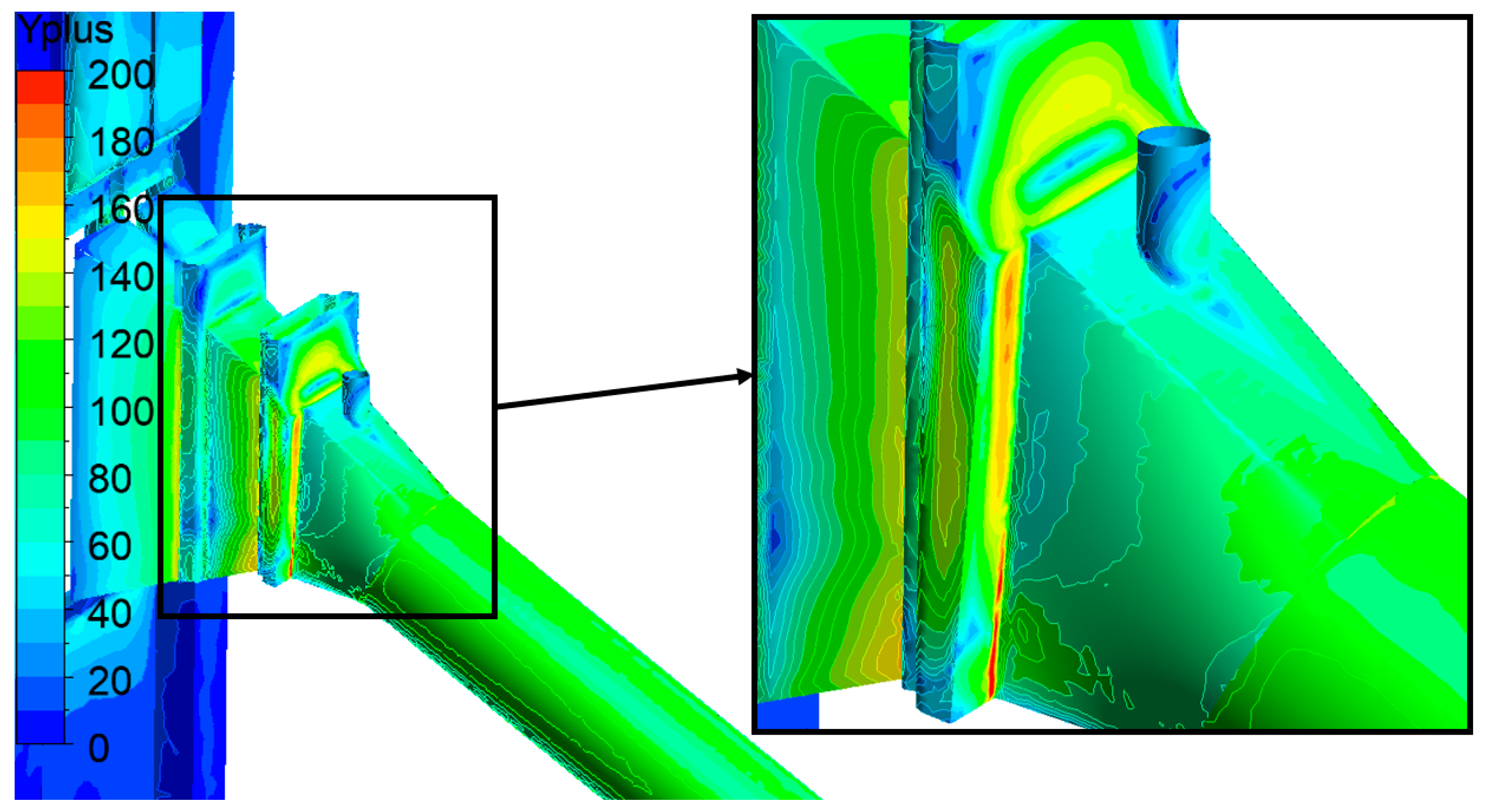
The creation of the mesh itself took place in the ICEM CFD 2021 R1 program. A high-quality structured mesh has been created for the essential part of the model (penstock). The remaining objects had an unstructured mesh with prismatic elements at the walls with a smooth transition into quads. The height of the elements at the walls was chosen so that for the design flow in the turbine regime (150 m3.s−1), the value of y+ was 100 to 200. The planned turbulence model is SST, and for the automatic wall function, all the first cells should be located in the log-law region near the wall [20] with y+ value between 30 and 200. The relationship between y+, the turbulence model and the wall function is discussed in detail Carloni et al. [21] or Nicolle et al. [22] A simplified mesh dependency test was performed on the computational grid size for 2 million and approximately 7.3 million elements (see details of mesh parts in Figure 3). The mesh size effect on the value of the hydraulics losses and the behaviour of the velocity field in the penstock was monitored. The resulting influence was minimal compared to model settings such as turbulence model and porous domain settings, and therefore, a detailed grid convergence index (GCI) analysis [23] was not performed. A grid with a higher number of elements was used for further calculation.

2.3.3. Numerical Setup

The setting of the CFD model corresponds to the purpose for which it is intended, i.e., obtaining an actual velocity and pressure field. The velocity field was used to assess flow measurement accuracy by the current meter and ultrasonic method. Therefore, it should sufficiently describe the secondary flow and the spatial distribution of velocities in magnitude and direction. The pressure field is vital for assessing the suitability of the Gibson method, especially the location of pressure taps.
The steady-state RANS CFD model was calculated in ANSYS CFX 2021 R1, which is an established commercial package with high accuracy and high-quality predictions of the behaviour of the given hydraulic problem. A “High-resolution” advection scheme was used, which allows automatic switching between the second- and first-order numerical schemes. The Shear Stress Transport (SST) k-omega model with an automatic wall function, originally introduced by Menter [24], was chosen as the turbulence model. This turbulence model combines the k-Epsilon model suitable for flow further away from the wall and the k-Omega model suitable for flow closer to the walls. Although the SST model is more commonly used in the numerical modelling of rotating machines [25,26] we use it in the modelling of pressure flow with the rotating flow. A test calculation was performed with the k-Epsilon turbulence model. However, due to the limited validation possibilities, the SST model was finally used, which should better describe the secondary flow in the penstock [21]. The calculation step is AutoTimescale—conservative with a factor of 0.25. This option results in an internal setting for calculating the timestep size dependent on velocities magnitude and mesh cell sizes.
Due to the nature of the task, the flow rate was set as a lower boundary condition at the plane in the lower guide vane ring. This lower boundary condition has been set as flow rate because we do not have the exact geometry of the existing turbine or the actual velocity field. However, in the turbine mode, the influence of the boundary shape and setting does not propagate too far upstream.
The upper boundary condition (the imaginary 3D plane in the reservoir) was set to Opening. This option best corresponds to the actual behaviour of the flow. For parts of domains representing walls, the No slip wall boundary condition was used. An equivalent sand grain roughness [27] of 0.5 mm is selected for steel parts such as D6250 pipe and spiral, and 4 mm for concrete walls (Table 2). Subsequently, the numerical model was validated both from the point of view of measured hydraulic losses and the distribution of velocities in the measuring section plane.

2.3.4. Comparison of Historical Measurements

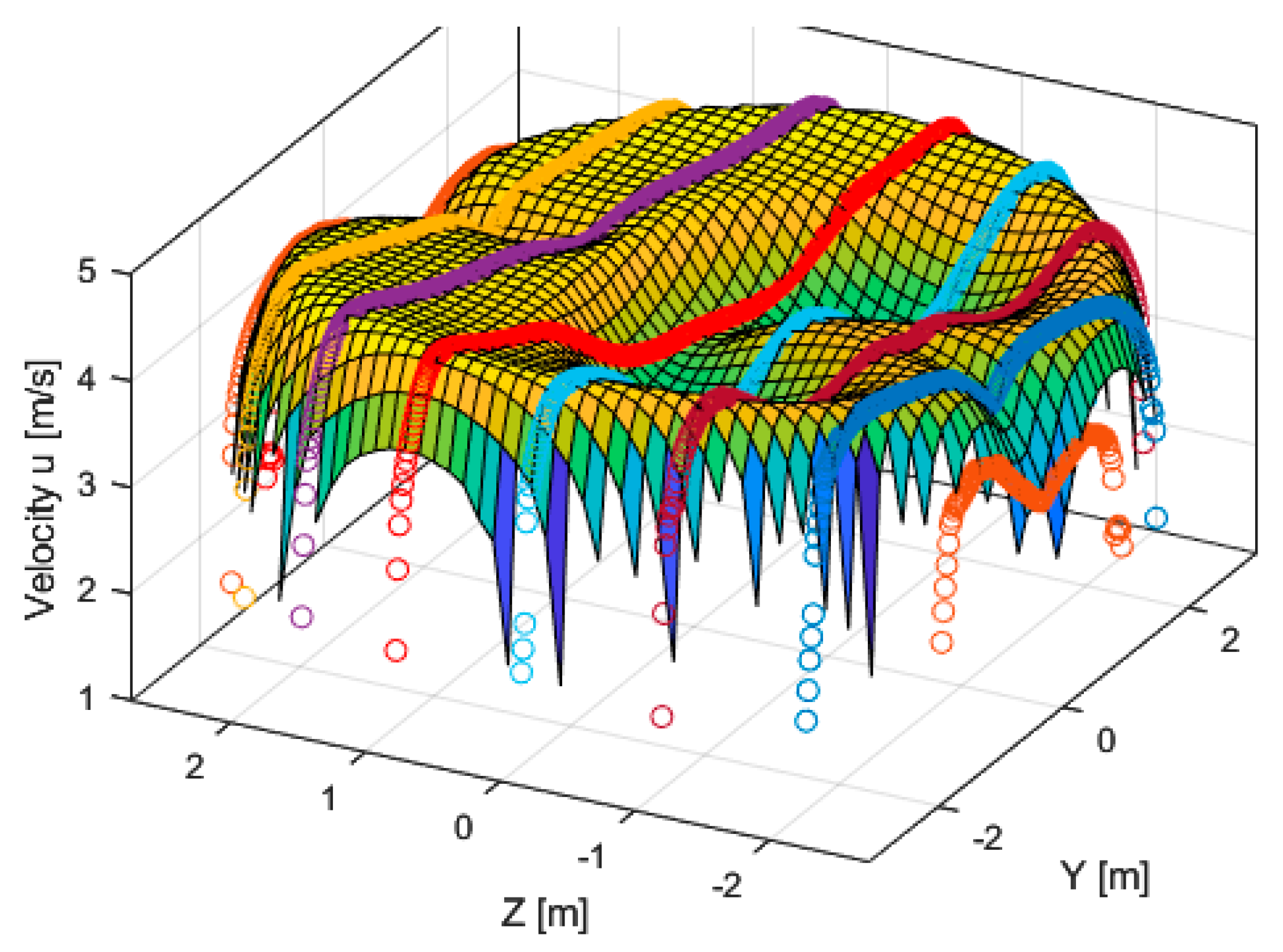
The velocity field measurement by current meters from 1994 was available for a flow rate of 105 m3.s−1. The resulting measured velocity fields in the plane of the eight-arm test section (Figure 4) were compared with the CFD results. According to the information available for the 1994 measurements, the uncertainty of the flow measurement was determined to be 1.2%. It should be noted here that this is an uncertainty in the calculation of the entire flow rate in the profile and does not describe an error in the description of the shape of the velocity field. Because the flow rates (respectively, mean velocity) in the numerical model and the actual measurement were not completely identical, the values had to be normalised to mean velocity of the profile (normalised normal velocities). The differences in point velocities between the actual measurement and the numerical model were then calculated (Figure 5).
When comparing the normalised velocities from 1994 and CFD, the differences are sometimes up to +−10%. Regarding the validation of the values measured by current meters, great care is needed, since no detailed information about the type of current meters was available, and the accuracy of the measuring section plane location is known to be about 0.5 m. The plane’s exact position is important, because the velocity field changes relatively significantly when stationed behind the bend.

2.3.5. Hydraulic Losses

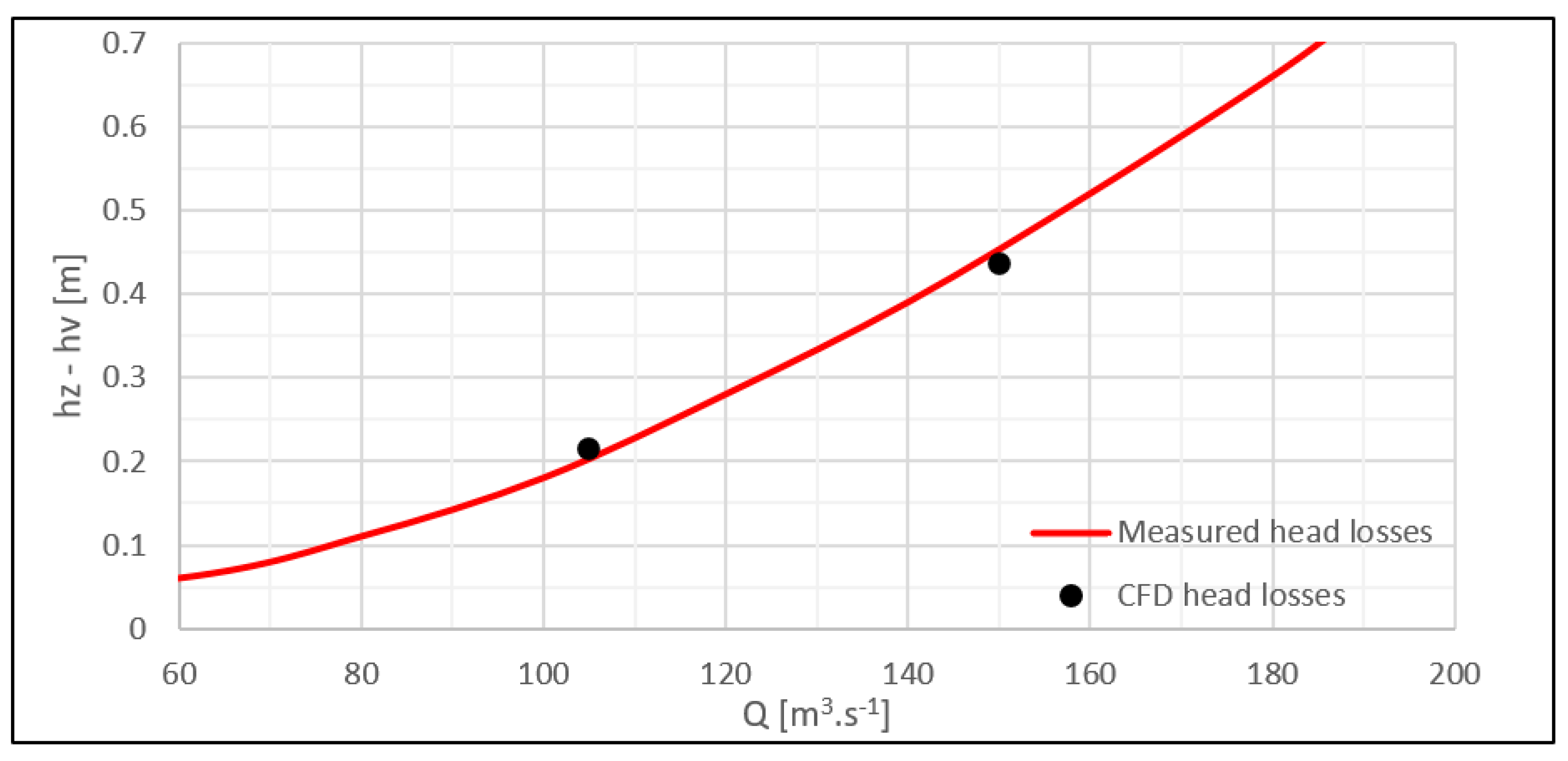
For the existing turbine operation and flow rates of 105 and 150 m3.s−1, a comparison was made with the measured values of the hydraulic losses of the entire penstock up to profile G2 (Figure 6). The measured flow values (red in the graph) represent the curve of the measured average values from the TG3 efficiency measurement from 1994. During the measurement, pressures were measured in the G2 profile, and the flow rate was determined using a measuring section plane in the profile marked in Figure 4.

3. CFD Simulations for Planned PSP

3.1. Turbine Regime
Next, the calculation of the future state after the change to PSP was started. All the following calculations were performed for the assumed new geometry and position of the guide and stay vanes. The influence of the spiral shape on the flow in the penstock in the turbine regime is negligible. First, the calculation was performed in the turbine regime for the assumed reversible Francis turbine nominal point of 150 m3.s−1.
In order to check the appropriateness of the element sizes at the walls in relation to the used turbulence model SST, the values of y+ on all walls of the model were displayed (Figure 7). The figure below shows the y+ values in the penstock. In the part of the main interest (inlet to the neck of the spiral), the average value is 93. In the detail of the figure, the parts in the grooves with higher y+ values are marked.
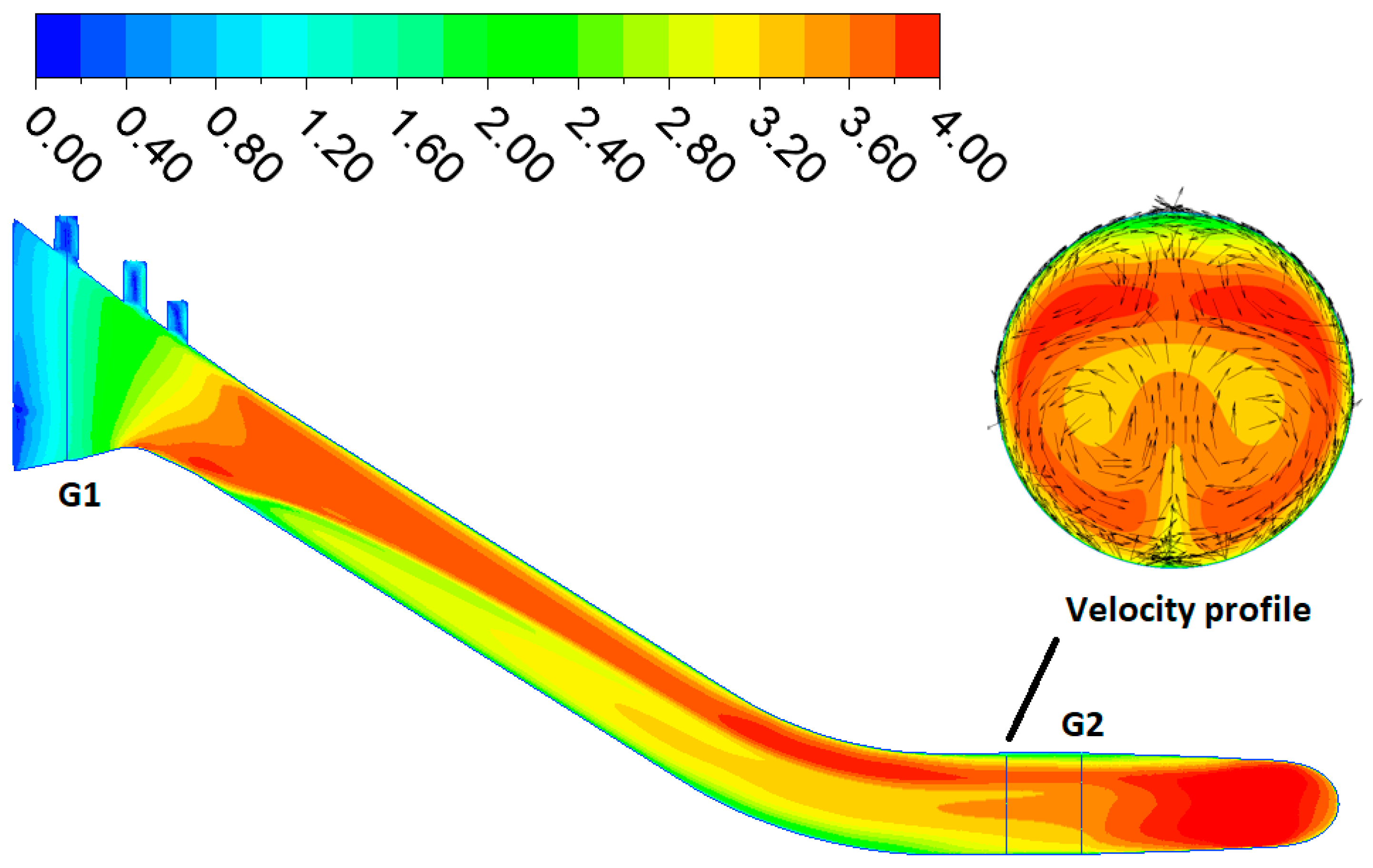
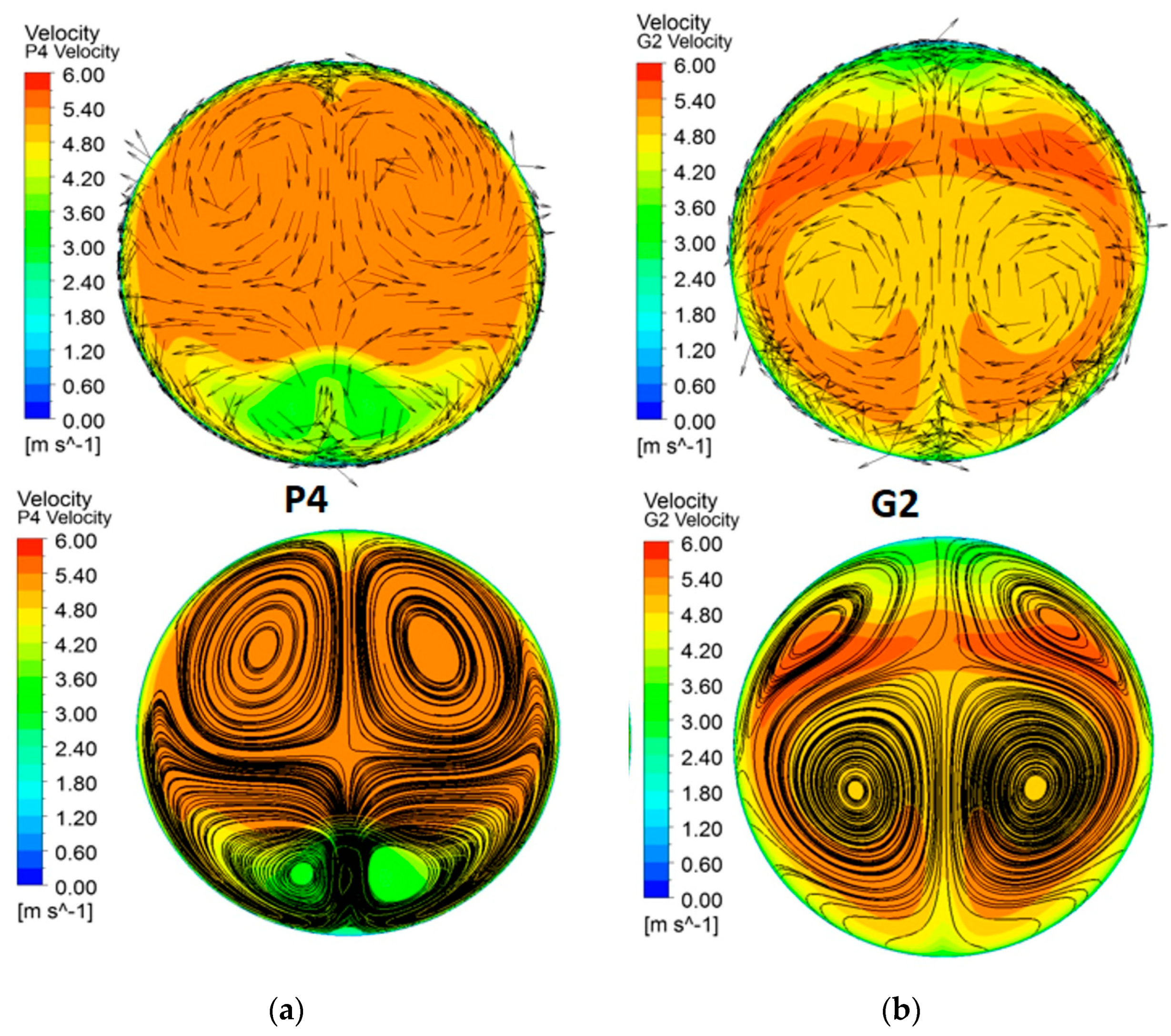
The figure below (Figure 8) shows the shape of the velocity fields in two selected section planes. Section plane P4 is in the upper part of the penstock and shows a low velocity in the lower part caused by the behaviour of the upstream part. Furthermore, section G2 is the interface between the penstock and the spiral and shows the transformation of the low speed in the lower part and the low speed in the upper part caused by the penstock bend (see the miniatures in Figure 9).
Note: The view of the cross-sections is always in the direction of the flow in the turbine regime.
Figure 9. Absolute velocity profiles (m.s−1)—longitudinal section with profiles miniatures.
Water 15 00779 g009
Furthermore, a contour graph of the angles formed by the normal velocity component and the absolute velocity vector (from now on referred to as swirl angle [28]) was created for individual section planes in the penstock (Figure 10).

3.2. Pump Regime

Furthermore, a calculation was made for the nominal pump mode of the reverse system for a flow rate of 110 m3.s−1. The boundary conditions have to be altered. The lower boundary condition is set, as the direction of the velocity vectors at the outlet of the distributor is very angled (the flow has a significant rotational component)—the rotational (tangential) component forms an angle of 61° with the normal (radial) component. This angle was determined according to the assumed nominal position of the guide vanes. A very similar shape is also found in the existing Dalešice PSP. A significant value is also the turbulence intensity at the inlet, which is set at a value of 5% by the example given by Feng et al. [29]. The upper boundary condition remains the same as in the turbine regime—set as Opening.
Furthermore, it is important to emphasize that this is an assumption of a steady flow and an artificially created velocity field simulating the behaviour of the assumed system in pump mode. In reality, there will be velocity and pressure field pulsations that cannot be well predicted without transient modelling of an actual turbine [30].
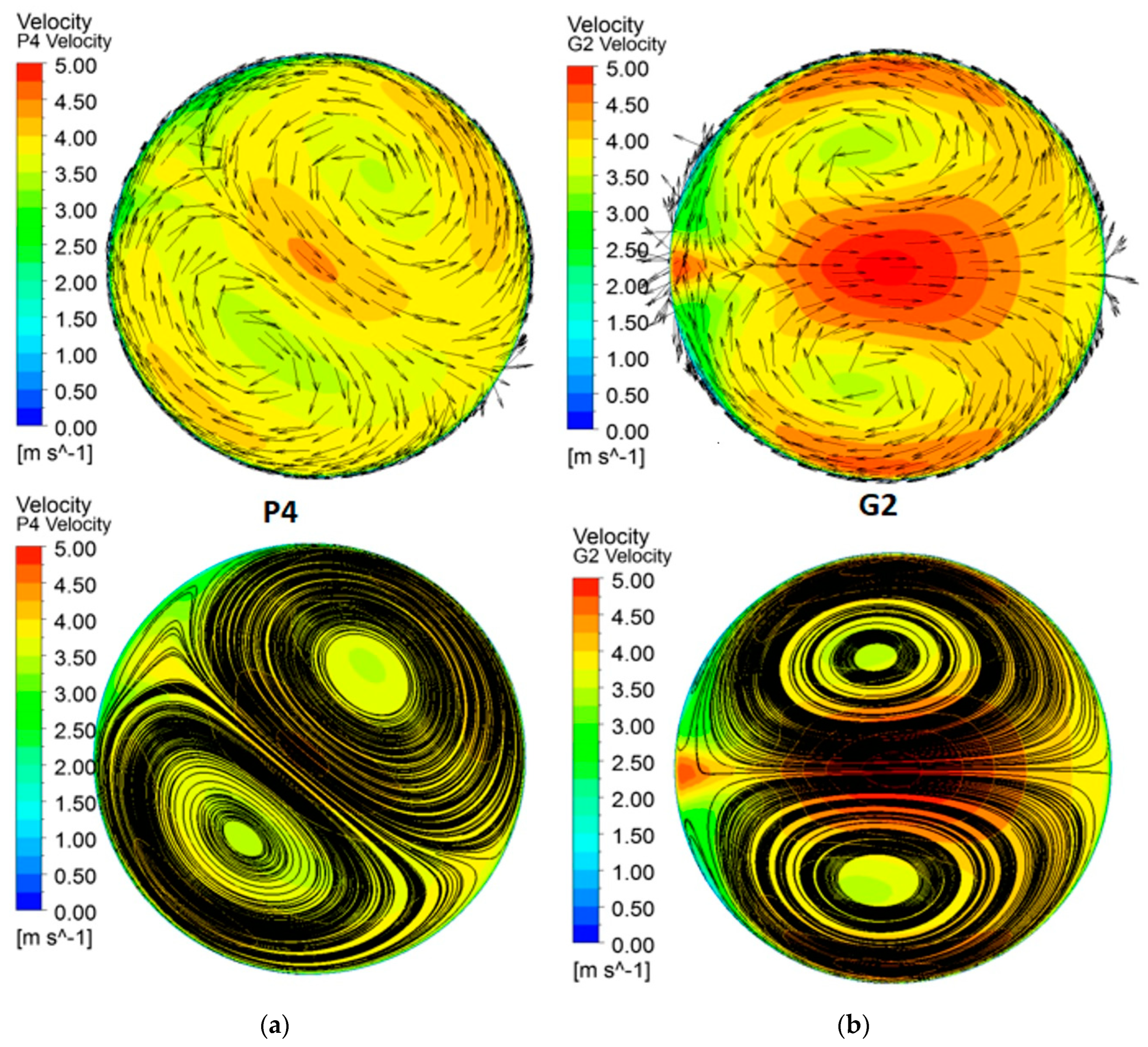
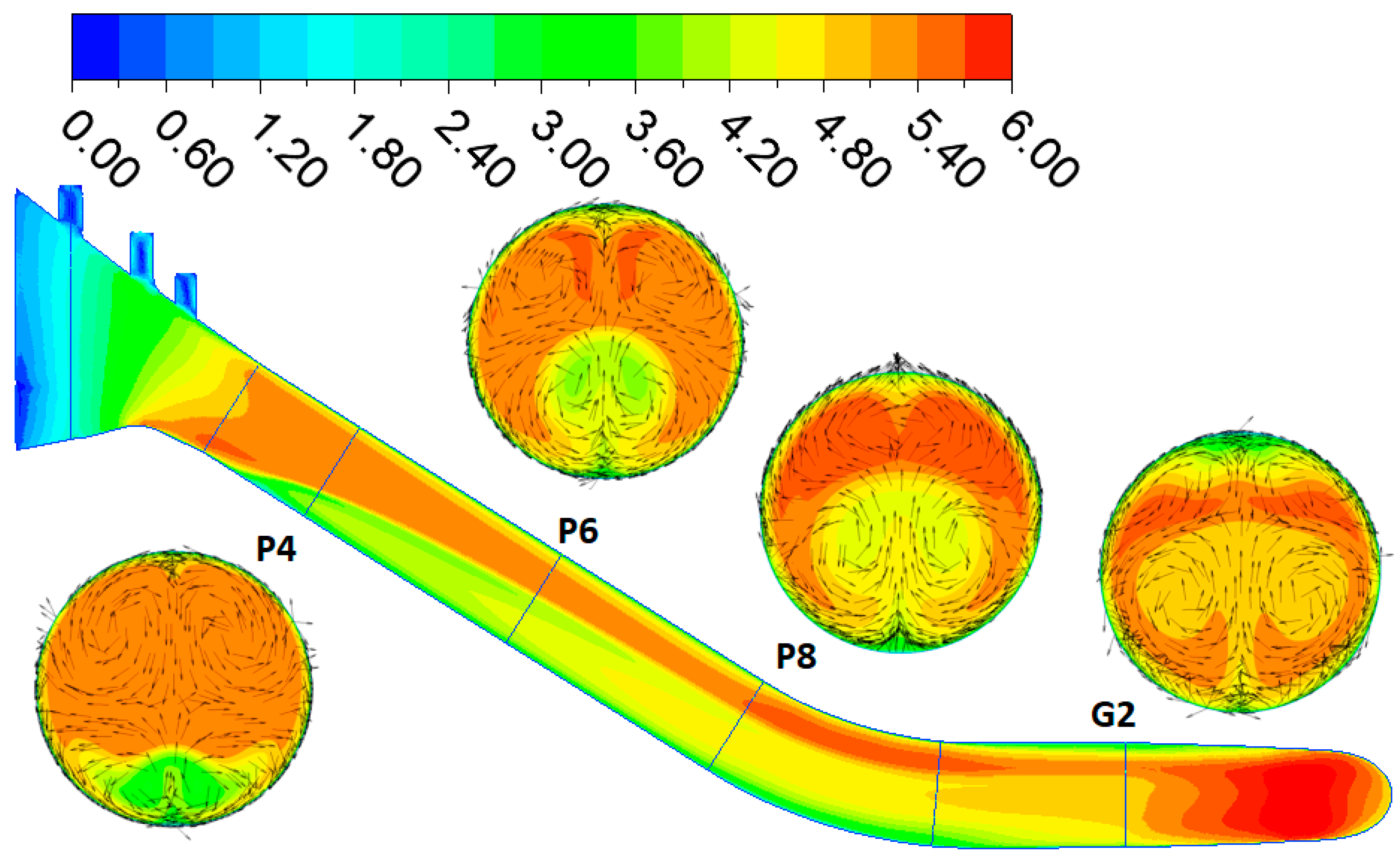
The velocity fields in two section planes of the penstock are shown below (Figure 11). Section plane G2 is located close to the interface of the DN6250 into the spiral, and the influence of the spiral and water flow from the reverse machine in pump mode can be seen. The current rotates rapidly in two parts (Figure 12). Due to the magnitude of the rotation, this influence is propagated up to the upper part of the penstock (profile P4). The current’s unevenness has already decreased, but it is still intensive. The nature of the rotation is similar, only due to the influence of the bend, the rotating parts were inclined by approximately 45°.
High swirl intensity reduces the accuracy of the flow measurement. The graphs (Figure 13) show the contours of the swirl angles. Contours are plotted for three profiles: P4, P6, and G2. The flow in pump operation has a solid rotational component, although the rotation decreases slightly along the length of the penstock (from G2 to P4).

3.3. Comparison of Turbine and Pump Regime

The goal of this study is to find one section suitable for flow measurement as an uncertainty compromise for both operating regimes. However, before that, it is necessary to compare the velocity and pressure fields for both regimes along the entire length of the penstock. In simple terms, in the case of flow in the turbine regime, the unevenness is caused by the inlet, which behaves like a bend. In the case of the pump regime, the double spiral flow is due to the shape of the spiral. Behind the bend, the double spiral flow inclines about 45°.

3.3.1. Coefficient for Non-Uniform Axial Velocity Profile [31]

For a rough idea of the homogeneity of the velocity field in the penstock, it is good to plot the values of the coefficient for non-uniform axial velocity profile α (which in the Czech environment is called the Coriolis number) after stationing. This number is a dimensionless parameter expressing the ratio of the actual kinetic energy to the velocity head expressed from the mean cross-sectional velocity. In a simplified way, it can be taken as information about the non-uniformity of the flow.
  α = S u 3 dS U 3 ¯ S
where u (m.s−1) is the point velocity, U ¯ (m.s−1) is the mean normal velocity, and S (m2) is the cross-sectional area.
In the figure above (Figure 14), the behaviour of α in both regimes can be seen. It is obvious that in the pump regime, the non-uniformity of the flow is much higher than in the turbine regime, which is due to the behaviour of the flow exiting the pump. In both cases, it gradually decreases, although in the case of the turbine regime, it increases slightly locally at the beginning of the bend (P8–P9).

3.3.2. Index of Asymmetry

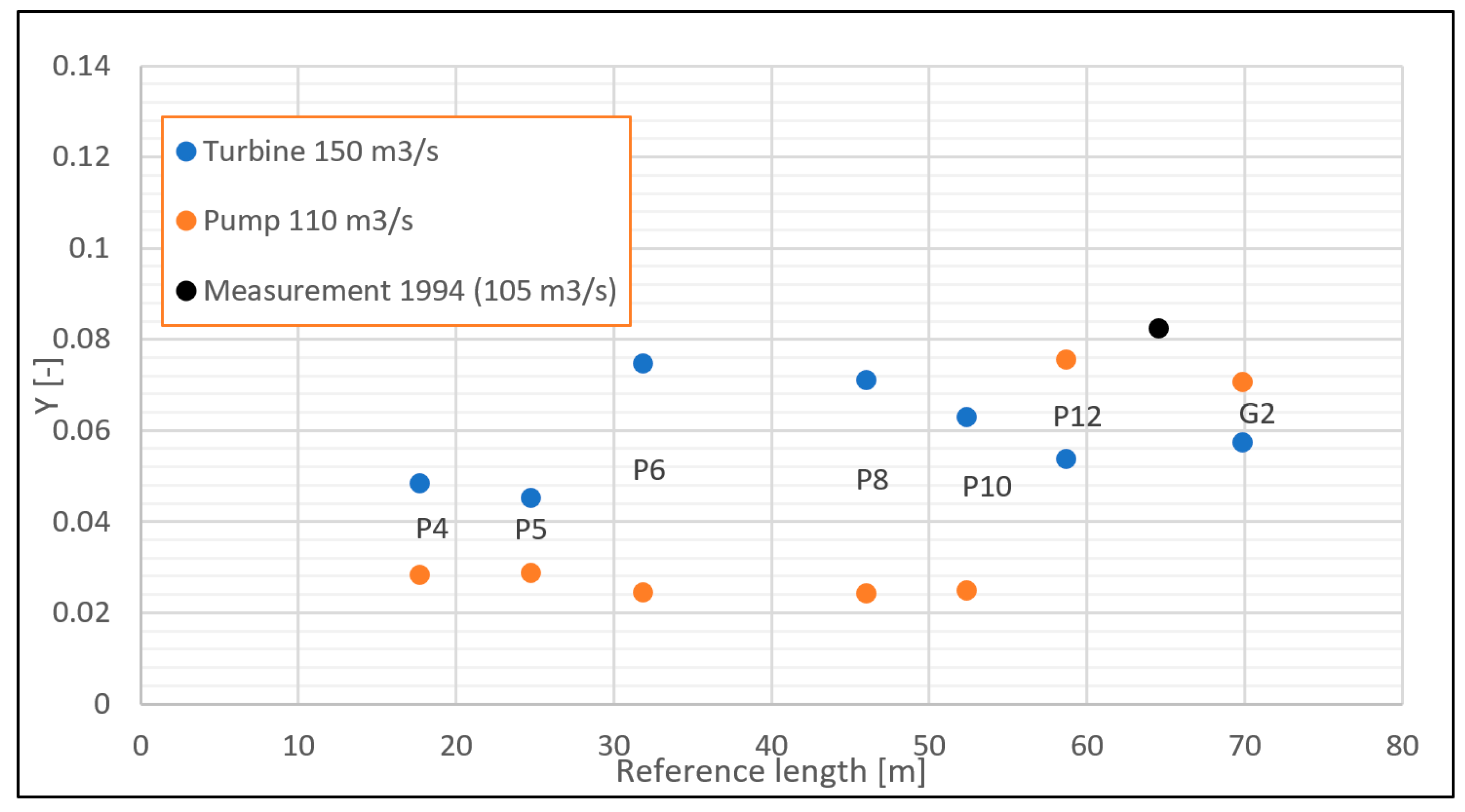
The asymmetry index was calculated for both regimes according to the ISO 3354 standard [28]. This index is calculated for the fictitious placement of cross-bars in individual profiles in the penstock (P4 to G2). The location of the current meters (points) on the cross is taken from GM 1994 measurements (eight radii with 57 points). In the intersections of individual current meter locations, this index of asymmetry is calculated from CFD results for both the turbine and pump regimes. The index is related to the error of evaluating the mean velocity from the measured point velocities.
Y = 1 U   [ ( U i U ) 2 n 1 ] 0.5
where Ui (m.s−1) is mean velocity calculated from the individual point velocity measurements in the i-th radius, U (m.s−1) is the mean axial fluid velocity calculated by ISO 3354, and n (-) is the number of radii.
Below (Figure 15) is a graph of the behaviour of the asymmetry index Y in the penstock. For measurements made in 1994, the value Y = 0.825 was calculated for a flow rate of around 105 m3.s−1. The value of the Y index is higher in the part closer to the spiral (P12 to G2) for the pump regime. However, in the straight upper section (P4 to P10), it is higher for the turbine regime. So, it says that at the upper section of the penstock, the non-uniformity of normal velocities for a given stationary array of current meters is higher in the turbine regime than in the pump regime and conversely.
Index Y takes only normal velocities into account and therefore only evaluates the non-uniformity of normal velocities and does not solve the rotational components of the flow. For this reason, there is no correlation between the coefficient α and the Y coefficient, which may seem counterintuitive at first sight.

3.3.3. Pressure Field in the Penstock

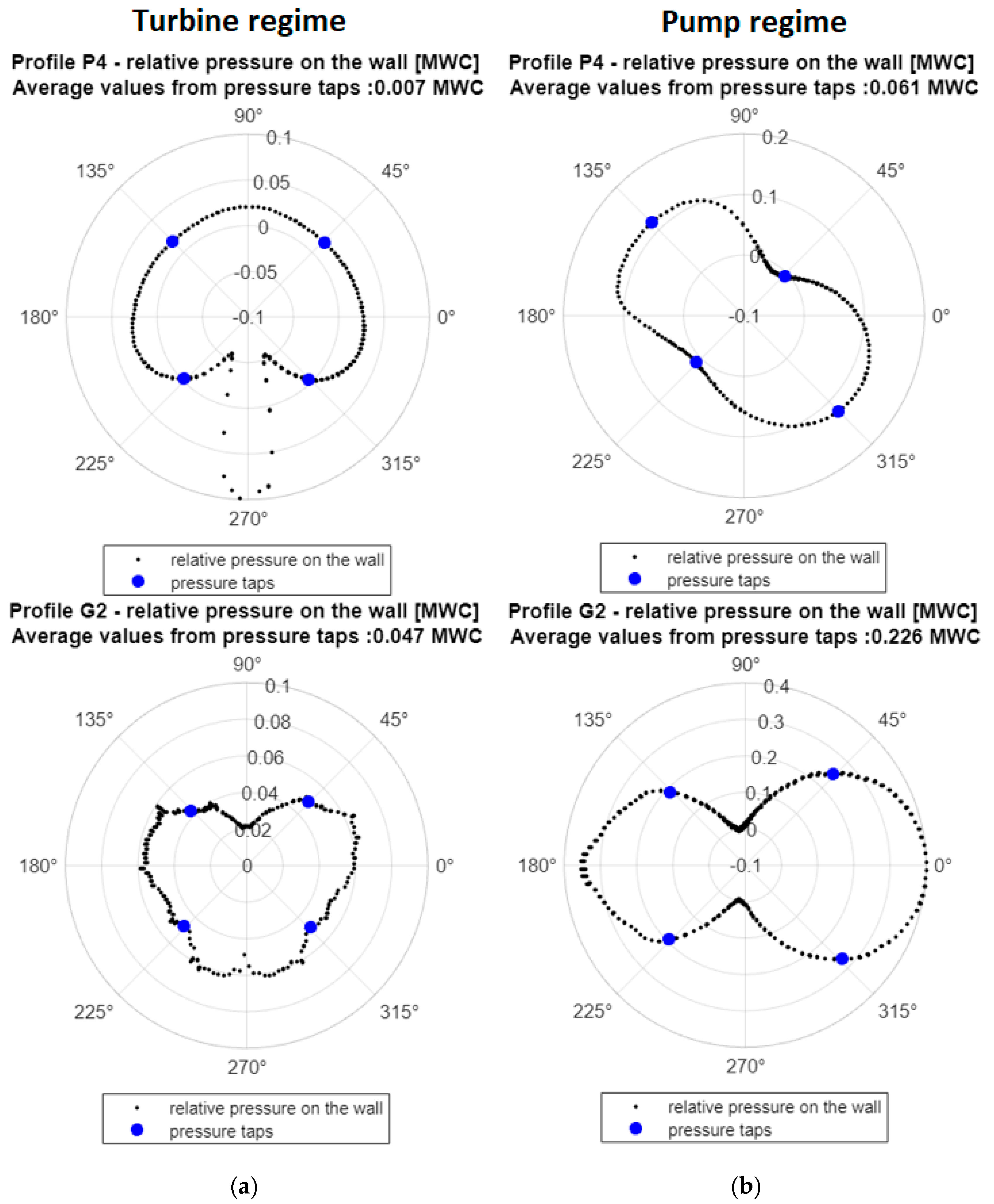
The analysis of pressure behaviour in the penstock is important not only for assessing the suitability of the Gibson method, but it also can be used for suitability assessment of the head measurement. Figure 16 depicts pressure contours in two profiles for the turbine and pump regimes, P4 and G2, respectively. The graphs show the relative pressure in the penstock wall, which are expressed in metres of water column. This “relative pressure” means the deviation of the pressure on the walls from the area averaged mean pressure in the given cross-section. At the same time, the pressure samplings in the individual quadrants are marked (in blue), and their mean pressure value compared to the mean pressure in the cross-section is calculated.
In the turbine regime, in profiles P4 and G2, the pressure values on the walls deviate by order of centimetres from the mean cross-sectional pressure. The mean value from imaginary pressure taps is 7 mm WC for profile P4 and 4.7 cm WC for profile G2, which are minimal deviations from the mean cross-sectional pressure.
In the pump regime, the values of deviations from the mean cross-sectional pressure are significantly higher, especially for the “lower” profile G2, where the mean relative pressure in the intakes is 0.226 m of the water column. This higher deviation can affect the precision of flow measurement using the pressure–time method and head measurements.
Due to the computational complexity, a transient analysis of the behaviour of the pressure when closing the guide vanes was unfortunately not performed. On this topic, we would like to highlight the articles by Saemi et al. [32] or [33].

4. Assessment of Flow Measurement Methods

The evaluation of the uncertainties of the three main methods of flow measurement—current meter method, pressure–time method, and ultrasonic method—is mainly based on standards, namely IEC 60041 [34], ASME PTV 18-2020 [35], ISO 3354 [28] or ISO 7194 [36]. “Main standards” such as IEC 60041 or ASME PTV 18 are relatively conservative in terms of geometric requirements. For this reason, standards that take into account the nature of the flow, such as ISO 3354, ISO 7194, and scientific literature, were used for the calculation of uncertainties.

4.1. Current Meter Method

This method of evaluating the flow is based on the measurement of point velocities using small current meters and the subsequent evaluation of the mean cross-sectional velocity, which is precisely specified by the ISO 3354 standard. According to the IEC 60041 standard, it is necessary to observe the lengths of the sections before and after the measuring profile, without asymmetric flow, etc. Due to the relatively short penstock, there is no place that meets the given geometric conditions. It is also necessary to use the ISO 3354 standard for at least indicative measurement uncertainty values. This standard stipulates that:
  • If the swirl angle is <5°, Y < 0.05 and low turbulence when applying 6 probe radii, the total uncertainty of the flow measurement can be below 1.5%
  • If the value of Y < 0.25 and when applying at least 6 measuring radii, the uncertainty of the flow measurement can be up to 2.2%.
It is also appropriate to mention other conditions here. One of the most important is the component effect of the water measuring current meters—the capability of the current meter registers only the velocity that is parallel with the current meter axis even when the flow is skewed. The next one is the sensitivity of the current meters to turbulence (a more significant moment of inertia of the current meters is necessary). The other is the necessity of a rigid frame (cross-bars) to fix the current meters.
The goal of the next presented calculation was comparison of the flow integrated using local velocities according to ISO 3354 and flow calculated in the CFD model. This calculation provides a rough estimate of error of local velocities integration based on ISO 3354.
The benefit of numerical modelling and virtual current metering is the ability to change the arrangement of the measuring profile and its location in the penstock, allowing for a relatively simple evaluation of mean velocity. However, this was different from the goal of our work. The topic of virtual current metering was addressed in more detail by Romero-Gomez et al. [37]
In the numerical model, it is possible to determine the mean cross-sectional values of the velocity very precisely. On the contrary, the evaluation of the mean velocity using the measured velocities by the current meters in the measuring cross is quite demanding, and it is necessary to observe the exact position of the current meters and other conditions described in ISO 3354. The methodology was adopted from the mentioned standard, which was also used in earlier measurements at the Orlík to evaluate the mean cross-sectional velocity, and the following was carried out:
  • The positions of the measuring profiles from the 1994 measurement in the TG3 penstock have been adopted.
  • For these positions, the values of normal velocities were subtracted from the CFD model simulation results.
  • The mean cross-sectional velocity was calculated from these values according to ISO 3354.
The relative deviations from the mean cross-sectional velocity from CFD in profiles P4, P8, and G2 in both the turbine and pump regimes were calculated from the read point values in the numerical analysis post-processing (Table 3). The deviation is evaluated as follows:
e = v ISO 3354 v CFD v CFD
where vISO3354 (m/s) is mean cross-sectional velocity calculated current meters by ISO 3354 and vCFD (m/s) is mean cross-sectional velocity from CFD-Post.
Since the deviations of the evaluation of the mean velocity from point velocities are mainly caused by the integration of point velocities according to ISO 3354, to a lesser extent, this is due to the coefficient m, which depends on the roughness of the wall. To the larger extent, the unevenness of the velocity field is indicated by whether the predetermined distribution of current meters according to ISO 3354 represents the distribution of the velocity field.
It should be emphasised here that this is only a deviation from the evaluation without further deviations from the real influence of the measurement, particularly the component effect of skew flow.

4.2. Pressure–Time Method (Gibson Method)

The pressure–time method evaluates the flow based on the measurement of the pressure increase during the closing of the gate (in our case, the guide vanes). In addition to accurate pressure measurement in two profiles with four pressure taps, it is necessary to precisely calculate the length and flow area of individual parts of the penstock to determine the penstock factor (geometrical factor) [38]. According to IEC 60041, if general conditions are met, the uncertainty is between 1.5 and 2%. According to ASME PTC 18, uncertainty of around +/−1% can be achieved. It should be mentioned here again that the standards are very conservative, and in the scientific literature, there are very often mentions of measurements carried out in non-compliance with the standards—at least there is often a bend section, a confusor, or a PSP bifurcation among the measuring profiles [39]. Even at peak-load hydropower plant Orlík and other Vltava Cascade power plants, measurements are typically performed in sections that, due to the parameters of the penstock itself, do not meet the standard requirements for locations.
Calculations of the main criteria were carried out according to the IEC 60041 standard (see the following Table 4). The value of the specific average hydraulic energy of the machine, E = 62 m w.c., is considered. For the flow rates and the pipe diameter D (m), the mean cross-sectional flow velocity U (m.s−1) is added. The variable pdyn (dynamic pressure) is the velocity head (the α value is considered equal to 1). In the standard, pdyn is also called specific kinetic energy.
According to the standard IEC 60041:
  • “Individual average pressure measurements around the measuring section should not differ from one another by more than 0.5% (0.5% E) of the specific hydraulic energy of the machine or 20% (20% pdyn) of the specific kinetic energy calculated from the average velocity in the measuring sections.” [34] (Chapter 11.4.2)
  • “… the difference between the pressure measured at any one tap and the average of the pressures measured at all taps shall not exceed 20% of the dynamic pressure (20% pdyn). The average of the readings from any pair of opposite taps shall not differ from the average from any other pair of taps in the same cross-section by more than 10% of the dynamic pressure (10% pdyn).” [34] (Chapter 10.4.2.4)
The table above (Table 4) was used to recommend the suitability of the profiles (tables in Chapter 5). After comparison with the real pressure distribution (Figure 16), it is possible to recommend profiles for pressure measurement. A clear overview of all profiles is given in Chapter 5.

Equivalent Geometrical Factor F

Especially with very short penstocks, we encounter the problem of accuracy in flow measurement. One of the problems is the value of the geometrical factor. The pressure–time method is derived for theoretical piston flow in the pipe. In a real short penstock with bend sections, such as Orlík, it is appropriate to take into account the effect of the velocity profile originally introduced by Adamkowski et al. [39,40,41].
In the Orlík locality, the pressure measurement is carried in the grooves of the stop logs (G1 profile) and in the G2 profile. The hydraulic flow conditions are not satisfactory, even in the simulated turbine regime. Therefore, a correction of the geometrical factor of the pipeline was carried out using CFD. Adamkowski [39] presents the entire procedure very clearly and in detail, so we only present our primary findings.
In short, the presented correction consists of two partial corrections: adjustment of the geometric flow areas to equivalent flow areas Aei and adjustment of the distances between the profiles to the distances between the centres of gravity of the individual profiles. In the circular profile penstock, the change in distances is negligible, and the change in flow areas is dominant.
For the pressure–time method, from the point of view of limiting the uncertainties of determining the geometric factor of the pipeline, we recommend using the existing lower profile G2 but shifting the upper profile to profile P4. Using these two profiles, the equivalent geometrical factor dF for the turbine regime is +1.25% larger than the simple geometrical factor, with an estimated degree of uncertainty of +/−0.3%. For the pump regime, the correction value (between P4 and G2) is +0.45%. Due to additional uncertainties, we do not dare to quantify the degree of uncertainty in the pump regime. This methodology was previously used at another peak-load hydro powerplant, Slapy, where, due to the very similar parameters of the penstock, we arrived at practically the same value. Adamkowski gives lower correction values but for incomparably longer penstocks (tens to hundreds of times the diameter). Our section of the penstock between P4 and G2 is only about eight times the diameter.

4.3. Ultrasonic Method

This method is based on the time shift of the time of passage of the signal through the water in the direction of the flow and against the direction of the flow. According to the IEC 60041 standard, this method is listed as Supplementary (Appendix J). However, in the ASME PTC 18-2020 standard, it is listed as one of the common flow measurement methods. Both standards agree on the geometric location of the profiles for measurement.
A. Voser [42] describes the issue of flow evaluation based on ultrasonic measurements in much more detail. This publication was subsequently used to evaluate the quantification of measurement uncertainties based on numerical simulation (tables in Chapter 5).
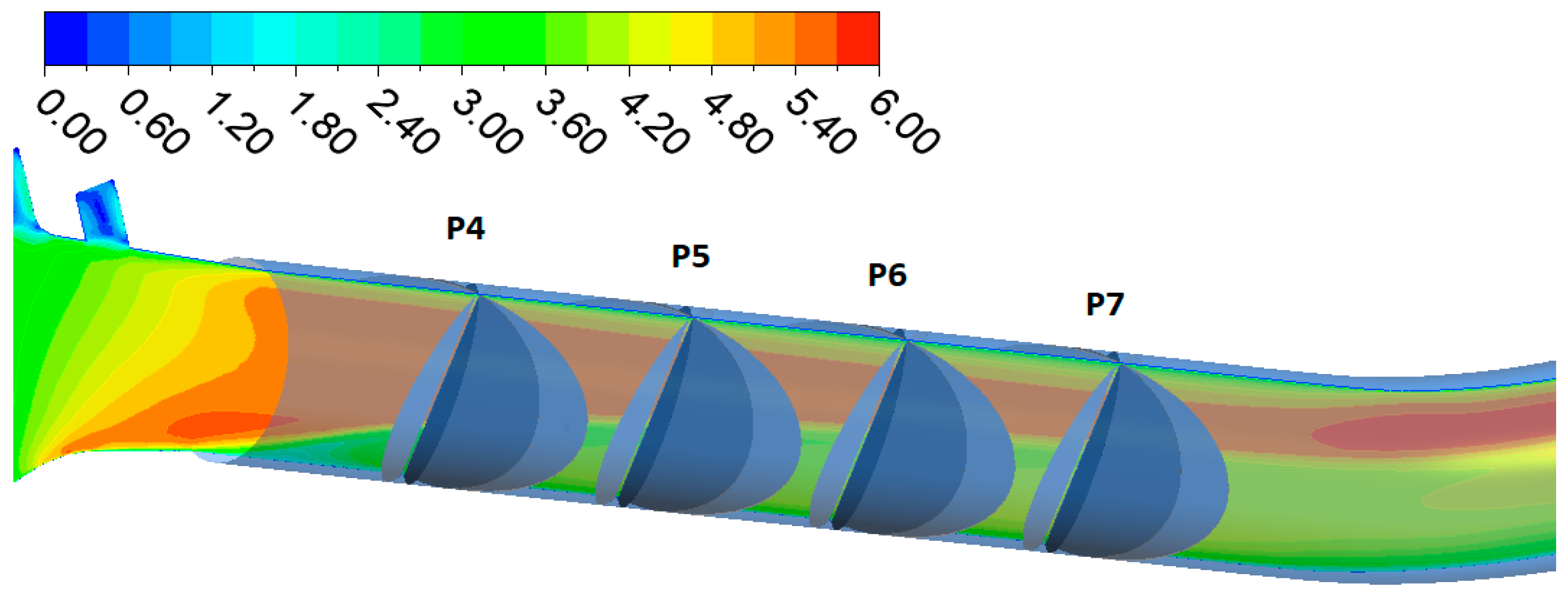
According to ASME PTC 18-2020, the flow for four selected profiles (P4 to P7) using four and nine chordal paths in two planes were calculated from the resulting CFD simulation for pump and turbine regimes. The angle between the planes was chosen in two variants, namely 45° and 65°. The flow was evaluated with chordal paths positioned according to the Gauss-Jacobi Method with OWICS weights according to ASME PTC 18-2020.
First, in CFD-Post, the corresponding rotated planes containing 45° and 65° were created in the positions of four profiles: P4, P5, P6, and P7 (Figure 17). Point values of velocities were exported for these planes, and the following process was performed in the MATLAB environment. A similar procedure was followed by Hug et al. [43], who directly exported the values of point velocities on the paths and subsequently performed vector operations to obtain the velocity in the direction of the paths and the transverse components. In our case, only the definition of the positions of the inclined planes in CFD is required, and all other operations are performed semi-automatically by a script. In a simplified way, the script procedure is as follows:
  • Definition of chordal path positions in the base plane.
  • Path rotation according to the position and inclination of the plane (A and B).
  • Extraction of velocity components at the intersection of the created paths and plane sections (A and B) (Figure 18).
  • Created averaged velocity components u, v, w.
  • Transformation of velocities into two components—in the path direction and transverse component.
  • The following flow calculation is exact according to ASME PTC 18-2020 for the given plane rotation and position in the conduit. The Gauss–Jacobi Method with OWICS weights was used in our case for four and nine paths.
Note: In our case, the speed of sound was set at 1435 m/s for 7 °C water.
Figure 17. A view of ultrasound planes With contour velocity (m.s−1).
Water 15 00779 g017
Figure 18. Interpolation of velocity components for 9 paths of plane A in pseudoplane ZY. The circle symbols represent the points with interpolated velocities of each ultrasonic path.
Water 15 00779 g018
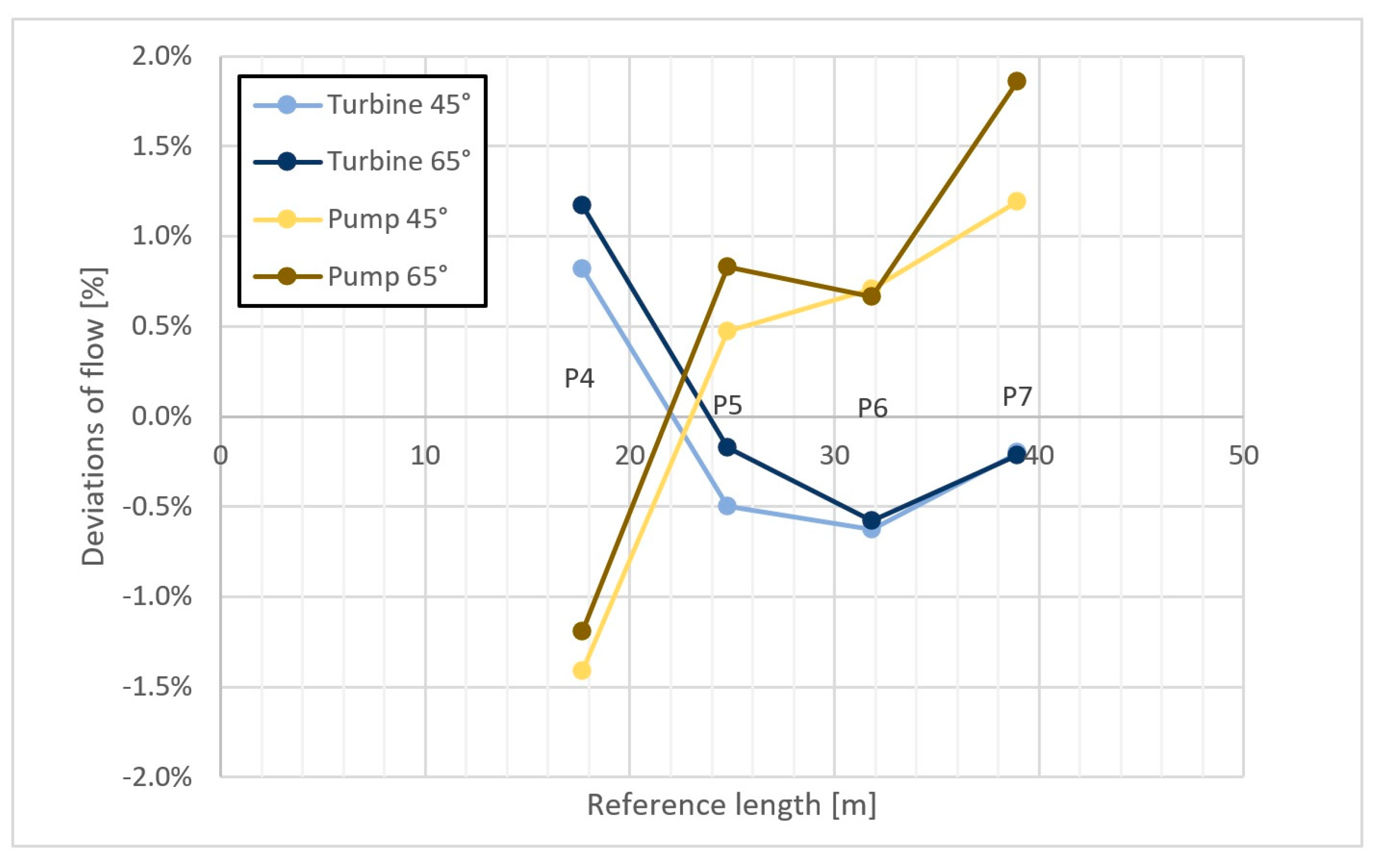
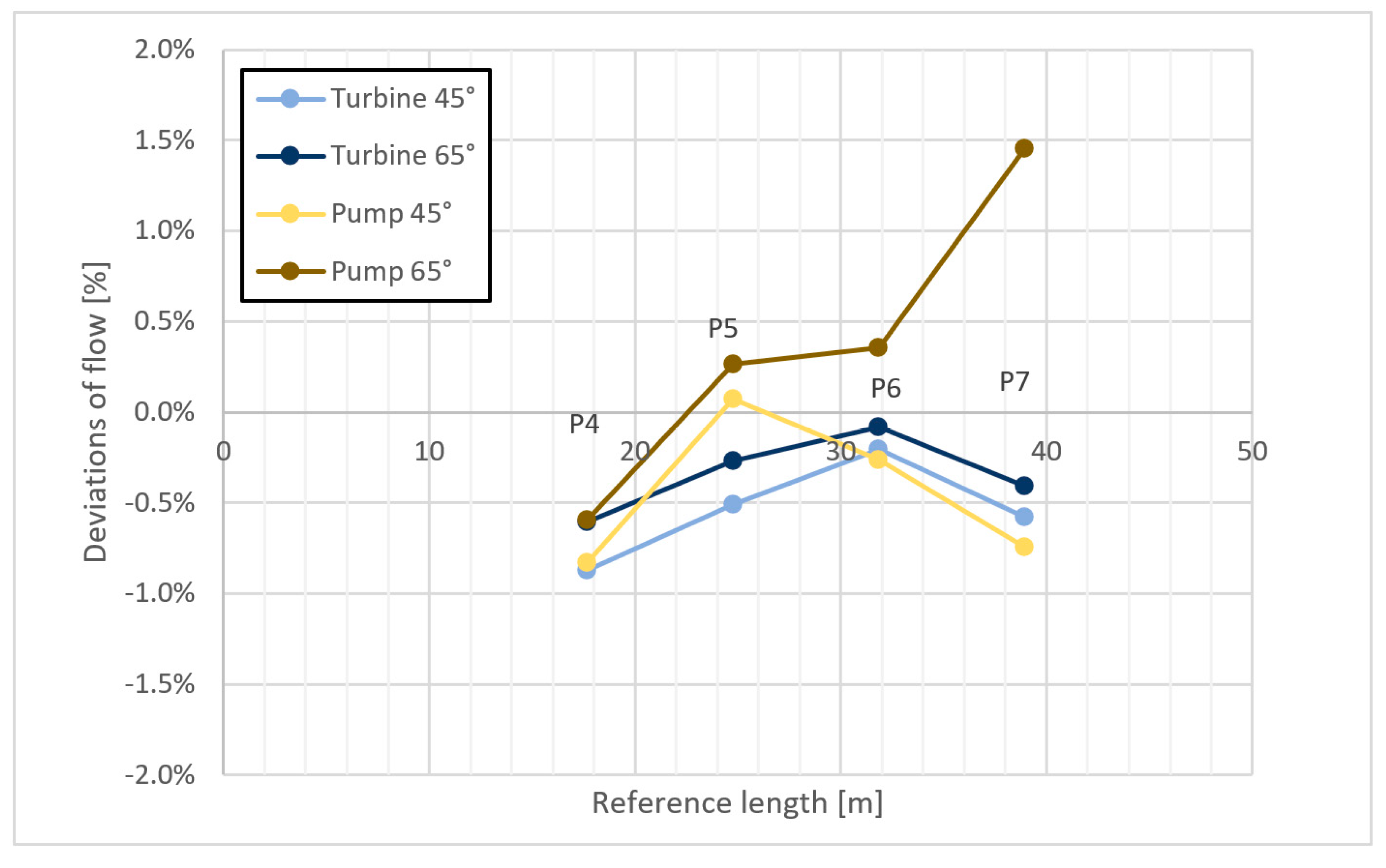
Since the exact values of the flow rates in both regimes are known in CFD, it is possible to determine the deviation of the flow rates evaluated by the integration of velocities on the chordal paths and the flow rates from CFD (Figure 19 and Figure 20). The deviation is evaluated as follows:
e = Q ultrasonic Q CFD Q CFD
where Qultrasonic (m3.s−1) is a flowrate calculated from paths by integration with using the Gaus–Jacobi method with OWICS weights and QCFD (m3.s−1) is a flowrate from CFD-Post.
The following is a graph with an evaluation of the percentage deviations in the individual profiles of the penstock. The deviation values from planes A and B are averaged. The evaluation was performed for plane angles of 45° and 65°, which are the boundary values recommended by the ASME PTC 18-2020 standard (in contrast, IEC 60041 gives a maximum angle of 75°).
From the graphs above, it can be clearly seen that higher number of paths will reduce the deviation in both the turbine and pump regimes. The influence of the path plane angle itself is marginal. The smallest deviations are achieved for the 2 × 9 path method in the P6 profile, where the deviations for both regimes are up to +−0.5%. A slightly higher deviation is in the P5 profile. Both profiles P5 and P6, when using 2 × 4 paths, are also suitable, with a deviation of up to +−1% for both regimes. We emphasise that the evaluation is carried out for a steady-state simulation; thus, pulsations and fluctuations, which can be expected especially in a pump regime, are not included. At the same time, no other uncertainties are affected, such as the protrusion effect and other errors arising during accurate measurement by the ultrasonic method.

5. Tables of Suitability of Measurement Profiles and Uncertainty Quantification

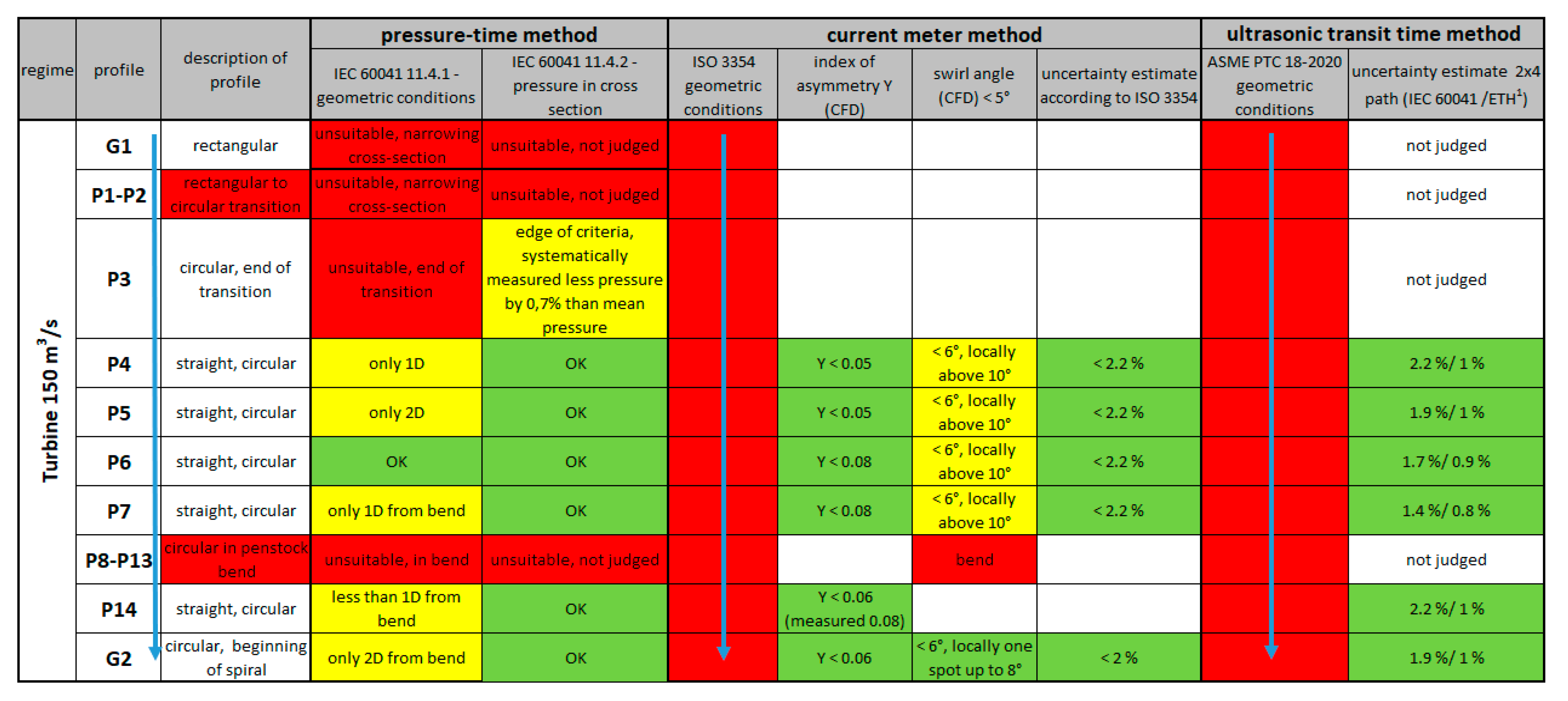
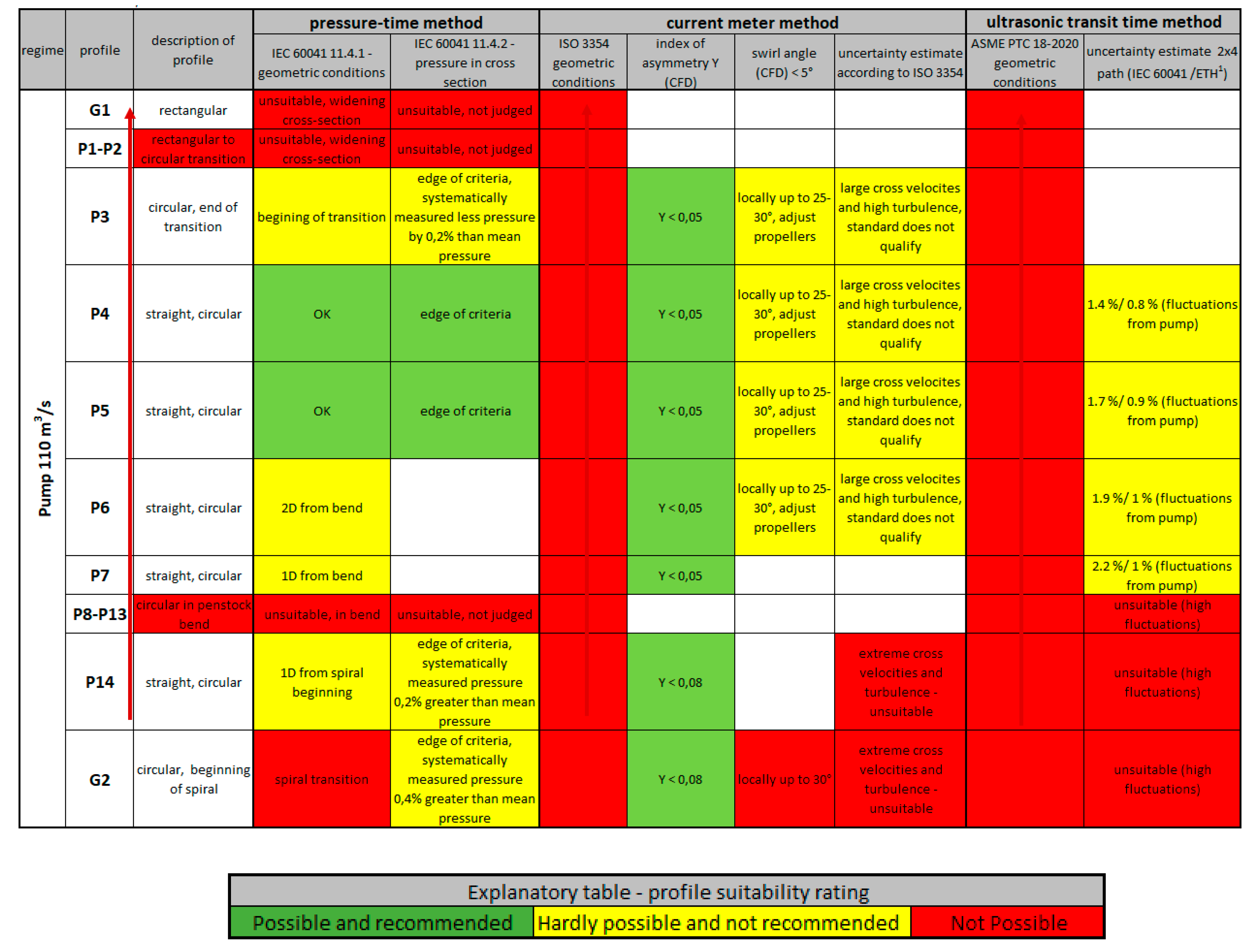
The following tables (Table 5 and Table 6) are used to assess the suitability of individual profiles and selected types of measurements for turbine and pump operation. It is important to note that the measurement in the profile refers only to the current meter method; when using the ultrasonic method, a short section (paths in oblique sections) is used, and when using the pressure–time method, it is a part of the penstock between two profiles.
According to the conservative geometric requirements of the ASME PTC 18 and IEC 60041 standards, no method can be used for both flow regimes.
Uncertainties were evaluated from the CFD flow analysis, according to the standards and scientific literature mentioned in Chapter 4. When measuring with current meters, it will not be possible to measure in the pump regime due to the large transverse velocity components (swirl angle), which excludes the use of this method for both regimes. In the case of pressure–time measurement, according to the given pressure distributions in the profiles, it is possible to measure using a pair of profiles P4 and P14, or P4 and G2, possibly using the upper profile P5. However, using this profile would shorten the section, so it will likely increase uncertainties and evaluation errors.
In the case of ultrasonic measurement, for both regimes of operation, it is suitable to place it in an inclined, straight section, preferably around profile P4 or P5, where the lowest uncertainty will be achieved. The table shows the uncertainty evaluation using four paths in two inclined planes. Following the ASME PTC 18-2020 standard, we recommend using a higher number of paths in each plane to minimise the evaluation error and thereby further reduce the value of uncertainties, especially for measurements in the pump regime. Another topic of discussion may be the rotation of the chordal paths around the centreline of the penstock.

6. Conclusions

The primary goal of this work was to objectively evaluate the suitability of the three chosen methods for flow measurement in a short penstock using CFD techniques. The uncertainty of the flow measurement, particularly for the current meter and ultrasonic, was also assessed in addition to the position recommendation.
It is vital to choose the appropriate method and measuring position that will provide the lowest level of uncertainty for both operating regimes, since the quantified accuracy of the flow measurement is carefully determined in the tender documents for the selection of the equipment technology supplier. Due to the hydraulic behaviour of the penstock being much more problematic under the pump regime, the resulting approach will be prone to minimising the uncertainties in this regime.
The classic method, historically widely used in the Czech Republic, is the current meter measurement. In the case of the Orlík penstock, measurements were previously carried out in the P14 profile. In the case of the pump regime, the use of the method is practically excluded due to the significant swirling of the flow. Another disadvantage is the installation of the measuring cross and, in the case of theoretical measurements in both regimes, the necessity to dewater the penstock three times and adjust the propeller in the direction of the pump regime. There is also a risk of the propeller coming loose and damaging the turbine.
The pressure–time method in the Czech Republic is also widely used on the short penstock of the Vltava Cascade in turbine mode. For the Orlík penstock, the pressure in the G1 and G2 profiles was used for pressure measurement. Pressure–time measurement in turbine mode is possible. The measurement in the pump regime has uncertainties that are difficult to quantify. According to our analysis of the pressure field, the applicability of the method is on the edge, and the pulsations and fluctuations of the actual pump have not been considered. It is also essential to accurately determine the amount of leakage through closed guide vanes. According to our experience, especially with short penstocks, the pressure measurement error increases significantly when the flow rate is lower. In particular, the error in the subsequent evaluation of the flow rate increases. A nice side effect when measuring pressures for the Gibson method is the ability to determine the net head.
Ultrasonic flow measurement is a novel method in the Czech Republic for large hydropower plants and is therefore approached with caution. The situation is not helped because it is listed as an additional method in IEC 60041. In contrast, we found support in the American standard ASME PTC 18-2020. The advantage of this standard is that it is frequently updated with the latest verified findings. In conjunction with the AMSE PTC-18 standard, and the scientific literature (especially A. Voser [42]), we were able to recommend profiles suitable for the use of this method and, at the same time, to quantify the uncertainty values.
The great advantage of this method is the possibility of using one set of sensors for both flow regimes and the possibility of continuous flow monitoring with outstanding accuracy, especially in the turbine regime. It is also possible to supplement ultrasonic transmitters and sensors with pressure evaluation sensors, which, together with pressure sampling in the G2 profile, would make it possible to use the pressure–time method for additional measurements.
The use of CFD modelling enabled an objective assessment of the flow measurement methods and the choice of the optimal location of the measuring profiles as a compromise between the turbine and pump regime in the pre-project phase. After the conversion of the Orlík to a PSP, it will be necessary to perform a numerical simulation with the actual shapes of the turbine for high-quality flow measurement with the lowest possible degree of uncertainty. The ideal would be to create a digital twin model and test the behaviour of the penstock and its effect on the calibration of the flow measurement method. It should be noted here that it would be advisable to scan the entire profile of the penstock precisely. At the same time, it would be necessary to have a model of the installed machinery available for a credible simulation of the future and actual state, ideally by transient simulation.
Despite all the research being related to the Orlík, the methodology mentioned earlier (combining CFD results, standards, and scientific literature to recommend suitable methods and their location) is valid for all types of penstocks, not only on the Vltava River Cascade.

Author Contributions

Conceptualisation, J.S. and P.N.; methodology, M.K.; software, J.S.; validation, J.S.; formal analysis, J.S., P.N., M.K. and R.V.; investigation, J.S., P.N. and M.K.; resources, J.S.; data curation, J.S., M.K.; writing—original draft preparation, J.S.; writing—review and editing, J.S., P.N., R.V.; visualisation, J.S.; supervision, P.N.; project administration, P.N.; funding acquisition, P.N., R.V. All authors have read and agreed to the published version of the manuscript.

Funding

The results presented here were part of contract research (contract no. 4102545468) funded by company ČEZ a.s.

Data Availability Statement

Not applicable.

Acknowledgments

We thank ČEZ a.s., which enabled the publication based on the contract research project—Future PSP Orlík—assessment of the suitability of flow measurement on a penstock.

Conflicts of Interest

The authors declare no conflict of interest.

References

  1. Zipf, M.; Most, D. Impacts of volatile and uncertain renewable energy sources on the German electricity system. In Proceedings of the 2013 10th International Conference on the European Energy Market (EEM) 2013, Stockholm, Sweden, 27–31 May 2013; pp. 1–8. [Google Scholar]
  2. Talaat, M.; Elkholy, M.; Farahat, M. Operating reserve investigation for the integration of wave, solar and wind energies. Energy 2020, 197, 117207. [Google Scholar] [CrossRef]
  3. Amiryar, M.; Pullen, K. A Review of Flywheel Energy Storage System Technologies and Their Applications. Appl. Sci. 2017, 7, 21. [Google Scholar] [CrossRef] [Green Version]
  4. Hedlund, M.; Lundin, J.; de Santiago, J.; Abrahamsson, J.; Bernhoff, H. Flywheel Energy Storage for Automotive Applications. Energies 2015, 8, 10636–10663. [Google Scholar] [CrossRef] [Green Version]
  5. Poland’s 820MWh pumped storage project to boost energy security. PEI 2022. Available online: https://www.powerengineeringint.com/energy-storage/polands-820mwh-pumped-storage-project-to-boost-energy-security/ (accessed on 8 December 2022).
  6. Luong, J.; Tran, C.; Ton-That, D. A Paradox over Electric Vehicles, Mining of Lithium for Car Batteries. Energies 2022, 15, 7997. [Google Scholar] [CrossRef]
  7. Gielen, D.; Gorini, R.; Leme, R.; Prakash, G.; Wagner, N.; Janeiro, L.; Collins, S.; Kadir, M.; Asmelash, E.; Saygin, D.; et al. World Energy Transitions Outlook: 1.5 °C Pathway, 1st ed.; IRENA: Abu Dhabi, the United Arab Emirates, 2021; ISBN 978-92-9260-334-2. [Google Scholar]
  8. Olabi, A.; Onumaegbu, C.; Wilberforce, T.; Ramadan, M.; Abdelkareem, M.; Al–Alami, A. Critical review of energy storage systems. Energy 2021, 214, 22. [Google Scholar] [CrossRef]
  9. Sandia National Laboratories DOE OE Global Energy Storage Database. Available online: www.sandia.gov/ess-ssl/global-energy-storage-database-home/ (accessed on 8 December 2022).
  10. Blakers, A.; Stocks, M.; Lu, B.; Cheng, C. A review of pumped hydro energy storage. Prog. Energy 2021, 3, 18. [Google Scholar] [CrossRef]
  11. Mongird, K.; Baxter, R.; Sprinkle, V. Energy Storage Grand Challenge Cost and Performance Assessment 2020: Technical Report; No. DOE/PA-0204 2020; First Edition, US Department of Energy: Washington, DC, USA, 2020.
  12. Pitorac, L.; Vereide, K.; Lia, L. Technical Review of Existing Norwegian Pumped Storage Plants. Energies 2020, 13, 4918. [Google Scholar] [CrossRef]
  13. Figgener, J.; Stenzel, P.; Kairies, K.; Linßen, J.; Haberschusz, D.; Wessels, O.; Angenendt, G.; Robinius, M.; Stolten, D.; Sauer, D. The development of stationary battery storage systems in Germany—A market review. J. Energy Storage 2020, 29, 20. [Google Scholar] [CrossRef]
  14. Ershad, A.; Ueckerdt, F.; Pietzcker, R.; Giannousakis, A.; Luderer, G. A further decline in battery storage costs can pave the way for a solar PV-dominated Indian power system. Renew. Sustain. Energy Transit. 2021, 1, 20. [Google Scholar] [CrossRef]
  15. van der Horst, D. NIMBY or not? Exploring the relevance of location and the politics of voiced opinions in renewable energy siting controversies. Energy Policy 2007, 35, 2705–2714. [Google Scholar] [CrossRef] [Green Version]
  16. Lugauer, F.; Kainz, J.; Gehlich, E.; Gaderer, M. Roadmap to Profitability for a Speed-Controlled Micro-Hydro Storage System Using Pumps as Turbines. Sustainability 2022, 14, 653. [Google Scholar] [CrossRef]
  17. Bayazıt, Y.; Bakış, R.; Koç, C. A study on transformation of multi-purpose dams into pumped storage hydroelectric power plants by using GIS model. Int. J. Green Energy 2021, 18, 308–318. [Google Scholar] [CrossRef]
  18. Teitel, M.; Dvorkin, D.; Haim, Y.; Tanny, J.; Seginer, I. Comparison of measured and simulated flow through screens: Effects of screen inclination and porosity. Biosyst. Eng. 2009, 104, 404–416. [Google Scholar] [CrossRef]
  19. Latif, M.; Sarwar, M.; Farooq, R.; Shaukat, N.; Ali, S.; Hashmi, A.; Tariq, M. Estimating Energy Efficient Design Parameters for Trash Racks at Low Head Hydropower Stations. Water 2022, 14, 2609. [Google Scholar] [CrossRef]
  20. Versteeg, H.; Malalasekera, W. An Introduction to Computational Fluid Dynamics: The Finite Volume Method, 2nd ed.; Pearson Prentice Hall: Harlow, UK, 2007; ISBN 978-013-1274-983. [Google Scholar]
  21. Carloni, A.; Conde, K.; Pantaleão, A.; Azevedo, J.; Rade, D. Validation and analysis of turbulence modeling in pipe elbow under secondary flow conditions. J. Braz. Soc. Mech. Sci. Eng. 2022, 44, 14. [Google Scholar] [CrossRef]
  22. Nicolle, J.; Cupillard, S. Prediction of dynamic blade loading of the Francis-99 turbine. J. Phys. Conf. Ser. 2015, 579, 17. [Google Scholar] [CrossRef] [Green Version]
  23. Celik, I. Procedure for Estimation and Reporting of Uncertainty Due to Discretization in CFD Applications. J. Fluids Eng. 2008, 130, 4. [Google Scholar]
  24. Menter, F. Two-equation eddy-viscosity turbulence models for engineering applications. AIAA J. 1994, 32, 1598–1605. [Google Scholar] [CrossRef] [Green Version]
  25. Liu, J.; Liu, S.; Wu, Y.; Jiao, L.; Wang, L.; Sun, Y. Numerical investigation of the hump characteristic of a pump-turbine based on an improved cavitation model. Comput. Fluids 2012, 68, 105–111. [Google Scholar] [CrossRef]
  26. Kantor, M.; Chalupa, M.; Souček, J.; Bílkova, E.; Nowak, P. Application of genetic algorithm methods for water turbine blade shape optimization. Manuf. Technol. 2020, 20, 453–458. [Google Scholar] [CrossRef]
  27. Kadivar, M.; Tormey, D.; McGranaghan, G. A review on turbulent flow over rough surfaces: Fundamentals and theories. Int. J. 2021, 10, 34. [Google Scholar] [CrossRef]
  28. Measurement of Clean Water Flow in Closed Conduit—Velocity-Area Method Using Current-Meters in Full Conduits and Under Regular Flow Condition, 3rd ed.; International Organization for Standartization: Geneva, Switzerland, 2008.
  29. Feng, J.; Benra, F.; Dohmen, H. Comparison of Periodic Flow Fields in a Radial Pump among CFD, PIV, and LDV Results. Int. J. Rotating Mach. 2009, 2009, 1–10. [Google Scholar] [CrossRef] [Green Version]
  30. Hu, J.; Yang, J.; Zeng, W.; Yang, J. Transient Pressure Analysis of a Prototype Pump Turbine: Field Tests and Simulation. J. Fluids Eng. 2018, 140, 10. [Google Scholar] [CrossRef]
  31. Dauhlhaug, O. A Study of Swirl Flow in Draft Tubes. Master’s Thesis, NTNU, Trondheim, Norway, 1997. [Google Scholar]
  32. Saemi, S.; Cervantes, M.; Raisee, M.; Nourbakhsh, A. Numerical investigation of the pressure-time method. Flow Meas. Instrum. 2017, 55, 44–58. [Google Scholar] [CrossRef]
  33. Saemi, S.; Raisee, M.; Cervantes, M.; Nourbakhsh, A. Numerical Investigation of the Pressure-Time Method Considering Pipe With Variable Cross Section. J. Fluids Eng. 2018, 140, 15. [Google Scholar] [CrossRef]
  34. Field Acceptance Tests to Determine the Hydraulic Performance of Hydraulic Turbines, Storage Pumps and Pump-Turbines, 3rd ed.; International Electrotechnical Commision: Geneva, Switzerland, 1996.
  35. American Society of Mechanical Engineers. Hydraulic Turbines and Pump-Turbines: Performance Test Codes, 1st ed.; The American Society of Mechanical Engineeers: New York, NY, USA, 2020. [Google Scholar]
  36. Measurement of Clean Water Flow in Closed Conduit—Velocity-Area Methods of Flow Measurement in Swirling or Asymmetric Flow Conditions in Circular Ducts by Means of Current-Meters or Pitot Static Tubes, 2nd ed.; International Organization for Standartization: Geneva, Switzerland, 2008.
  37. Romero-Gomez, P.; Harding, S.; Richmond, M. The effects of sampling location and turbulence on discharge estimates in short converging turbine intakes. Eng. Appl. Comput. Fluid Mech. 2017, 11, 513–525. [Google Scholar] [CrossRef] [Green Version]
  38. Gibson, N. Measurement of the Flow of Fluids in Closed Conduits 1921; Patent and Trademark Office: Washington, DC, USA.
  39. Adamkowski, A.; Janicki, W.; Lewandowski, M. Measurements of Discharge through a Pump-Turbine in Both Flow Directions Using Volumetric Gauging and Pressure-Time Methods. Energies 2020, 13, 4706. [Google Scholar] [CrossRef]
  40. Adamkowski, A. Discharge Measurement Techniques in Hydropower Systems with Emphasis on the Pressure-Time Method. Hydropower-Pract. Appl. 2012, 29, 83–111. [Google Scholar]
  41. Adamkowski, A.; Krzemianowski, Z.; Janicki, W. Flow rate measurement using the pressure-time method in a hydropower plant curved penstock. In Proceedings of the 7th International Conference On Hydraulic Efficiency Measurements IGHEM 2008, Milan, Italy, 3–6 September 2018; p. 13. [Google Scholar]
  42. Voser, A. Analyse und Fehleroptimierung der Mehrpfadigen Akustischen Durchflussmessung in Wasserkraftanlagen. Ph.D. Thesis, ETH Zürich, Zürich, Switzerland, 1999. [Google Scholar]
  43. Hug, S.; Staubli, T.; Gruber, P. Comparison of measured path velocities with numerical simulations for heavily disturbed velocity distributions. In Proceedings of the 9th International Conference On Hydraulic Measurement and Efficiency IGHEM 2012, Trondheim, Norway, 27–30 June 2012. [Google Scholar]
Figure 1. Scheme of Vltava River Cascade (archive of CEZ Communications and CEZ Hydropower Plants).
Water 15 00779 g001
Figure 2. Part of 3D penstock model. Profiles P1 to P15 are artificially made for the purpose of the hydraulic characteristics evaluation. Profiles G1 and G2 represent actual profiles with the pressure taps for the pressure-time method.Each inlet is made up of a rounded intake object of a confusor shape with a rectangular cross-section (Figure 2—profiles P3 and upstream). The inlet is divided into two parts by a vertical inlet pillar. Two coarse screen sections with 140 mm spacing are supported by side walls and the inlet pillar. Then, there are the grooves of the stop logs, which are followed by the grooves of the emergency shut-down gate. This is followed by a transition piece from a rectangular cross-section to an inclined circular cross-section. In this transition piece, the DN 1200 pipe is included as an aeration for the eventual triggering of the shutdown gate. The transition piece is followed by a 6250 mm diameter penstock with a centreline length of approximately 59.1 m. This circular section consists of a 35.2 m long section with a slope of approx. 32° (Figure 2—profile P3 to P8). Next is the bend section and a short straight section to which the spiral is connected (Figure 2, profile P8 to G2). This is followed by a stay ring, guide vanes and an eight-bladed Kaplan turbine runner with a diameter of 4.6 m. The runner chamber is connected to an elbow draft tube.
Water 15 00779 g002
Figure 3. Example of computational grid: (a) part of water reservoir representing inlet, (b) intake section, (c) part of penstock.
Water 15 00779 g003
Figure 4. Profiles for current meter flow measurement and for hydraulic losses evaluation (G2).
Water 15 00779 g004
Figure 5. Normal velocities (position of current meters are marked with red dots): (a) Current meter measurement 1994, (b) Velocity contour for CFD, (c) Differences of normalised velocities (in %).
Water 15 00779 g005
Figure 6. Comparison of measured and CFD calculated losses in metres of water column.
Water 15 00779 g006
Figure 7. Values of y+ on the walls for turbine regime with flow of 150 m3.s−1.
Water 15 00779 g007
Figure 8. Absolute velocity contours: (a) in the profile P4, (b) in the profile G2. The arrows represent normalized velocity vectors projection, i.e., the behaviour of the non- normal velocity components (swirl velocity).
Water 15 00779 g008
Figure 10. Contours of swirl angles in degrees: (a) profile P4, (b) profile P5, (c) profile G2.
Water 15 00779 g010
Figure 11. Absolute velocity contours: (a) in the profile P4, (b) in the profile G2.
Water 15 00779 g011
Figure 12. Absolute velocity profiles (m.s−1)—longitudinal section with profiles miniatures.
Water 15 00779 g012
Figure 13. Contours of swirl angles in degrees: (a) profile P4, (b) profile P5, (c) profile G2.
Water 15 00779 g013
Figure 14. Comparison of α in turbine and pump regime after stationing.
Water 15 00779 g014
Figure 15. Index of asymmetry Y value after stationing in the penstock.
Water 15 00779 g015
Figure 16. Values of relative pressures (in metres of water column) on the wall for profiles P4 and G2: (a) turbine regime, (b) pump regime.
Water 15 00779 g016
Figure 19. Deviations for four-path method.
Water 15 00779 g019
Figure 20. Deviations for nine-path method.
Water 15 00779 g020
Table 1. Basic technical information: current state and an approximate planned state.
Table of Basic Technical
Information
Current StatePlanned State
Turbine TypeKaplanFrancisReversible Francis
TurbinePump
Heads range (m)45–71.545–71.550–71.550–71.5
Discharge range (m3.s−1)47.5–16080–15080–150110
Unit installed power (MW)91939176
Table 2. Basic variables.
VariableValueUnitsDescription
ρ999.9kg.m−3specific mass
ν1.43 × 10⁻⁶m2.s−1kinematic viscosity
D6250mmpenstock diameter
L69.92mcentreline length G1 to G2
Δ10.5mmequivalent sand grain roughness of steel
Δ1/D8 × 10−5-relative roughness of steel
Δ24mmequivalent sand grain roughness of concrete
Δ2/D6.4 × 10−4-relative roughness of concrete
Table 3. Deviations between values determined from the entire cross-section and from point values in post-processing of the numerical model according to ISO 3354.
DeviationP4P8G2
Turbine 150 m3.s−1−0.2%−1.4%−0.5%
Pump 110 m3.s−1−0.1%−0.3%+2.4%
Table 4. Criterion values according to IEC 60041 (green letters) for turbine and pump regime.
RegimeQDUpdyn20%pdyn10%pdyn0.5%E
(m3.s−1)(m)(m.s−1)(m w.c.)(m w.c.)(m w.c.)(m w.c.)
Turbine1506.254.91.20.240.120.31
Pump1106.253.60.70.130.070.31
Table 5. Recommending the applicability of profiles and quantifying the uncertainty of flow measurement for turbine regime. The arrows represent water flow in turbine regime.
Water 15 00779 i001
Note(s): 1 Voser, A. Analyse und Fehleroptimierung der Mehrpfadigen Akustischen Durchflussmessung in Wasserkraftanlagen. Ph.D. Thesis, Zürich, Switzerland, 1999, [42].
Table 6. Recommending the applicability of profiles and quantifying the uncertainty of flow measurement for pump regime.
Water 15 00779 i002
Disclaimer/Publisher’s Note: The statements, opinions and data contained in all publications are solely those of the individual author(s) and contributor(s) and not of MDPI and/or the editor(s). MDPI and/or the editor(s) disclaim responsibility for any injury to people or property resulting from any ideas, methods, instructions or products referred to in the content.