Article

Cost-Effective Natural Adsorbents for Remediation of Oil-Contaminated Water

by
Jenan A. Al-Najar
1,*,
Shurooq Talib Al-Humairi
1,
Tagreed Lutfee
1,
Deepanraj Balakrishnan
2,
Ibham Veza
3,
Manzoore Elahi M. Soudagar
4,* and
Islam M. R. Fattah
5,*
1
Chemical Engineering Department, University of Technology, Baghdad 10066, Iraq
2
College of Engineering, Prince Mohammad Bin Fahd University, Al Khobar 31952, Saudi Arabia
3
Department of Mechanical Engineering, Universiti Teknologi PETRONAS, Bandar Seri Iskandar 32610, Perak Darul Ridzuan, Malaysia
4
Department of VLSI Microelectronics, Saveetha School of Engineering, Saveetha Institute of Medical and Technical Sciences, Chennai 602105, Tamilnadu, India
5
Centre for Technology in Water and Wastewater (CTWW), School of Civil and Environmental Engineering, Faculty of Engineering and IT, University of Technology Sydney, Ultimo, NSW 2007, Australia
*
Authors to whom correspondence should be addressed.
Water 2023, 15(6), 1186; https://doi.org/10.3390/w15061186
Submission received: 15 February 2023 / Revised: 9 March 2023 / Accepted: 13 March 2023 / Published: 19 March 2023
(This article belongs to the Section Water Quality and Contamination)

Abstract

:
Oil-contaminated water is among the most significant environmental challenges from various industries and manufacturing processes. Oily water poses a severe environmental threat and is toxic to many forms of life. This study aims to investigate the potential of natural adsorbents, namely animal bones (ABs) and anise residues (ARs), for removing oil from water using a batch adsorption process. The effects of adsorbent dosage (0.2–2 g), oil concentration (200–1000 mg/L), and contact time (30–120 min) on the adsorption process were evaluated. This study is the first to employ ABs and ARs as adsorbents for oil removal, and their efficacy for this purpose has not been previously reported. The results indicate that ABs exhibit superior oil removal capacity compared to ARs. Specifically, ABs removed 45 mg/g of oil from water, while ARs removed only 30 mg/g of oil. Furthermore, ABs achieved a percentage removal rate of 94%, whereas ARs had a percentage removal rate of 70%. The adsorbents were characterised using Fourier transform infrared (FTIR) spectrometry, contact angle measurements before and after adsorption, and thermogravimetric analysis (TGA). In addition to the experimental analysis, several kinetic and adsorption models were employed to investigate the adsorption process. The pseudo-first-order and pseudo-second-order models were used to represent the kinetics of the reaction, while the Langmuir and Freundlich isotherm models were used to represent the adsorption isotherm. Marquardt’s percent standard deviation (MPSD) error function was used to confirm the fit of the experimental data with the isotherm model, in addition to the correlation coefficient R2. The isotherm studies indicated that the experimental data of the two adsorbents used with the Langmuir isotherm model were consistent with one another. The kinetics study demonstrated that the adsorption process using the two adsorbents adheres to a pseudo-second-order kinetics model.

1. Introduction

Oil-contaminated water is currently a significant environmental issue resulting from various industries and production processes, and it poses a serious threat to the environment and various life forms due to its toxicity [1,2]. Therefore, it is crucial to treat oily water and remove oil from water before discharging water into the environment. Different techniques have been employed for this purpose, including biological processes [3,4], ultrafiltration and nanofiltration [5], microfiltration [3], adsorption [6,7,8], de-emulsification [9], reverse osmosis [10,11], advanced oxidation processes [12], flocculation, electrocoagulation, chemical coagulation, and electroflotation [13,14]. However, these techniques have limitations and often involve high capital and operational costs. Among these techniques, adsorption has emerged as an efficient method for removing oil pollutants from water, involving the adsorption of oil pollutants on the surface of the adsorbent.
Oil adsorption refers to the process of oil molecules being attracted to the surface of a sorbent [15]. A variety of physical forces, including Van der Waals forces, hydrophobicity, hydrogen bonding, polarity and steric interactions, dipole-induced dipole interactions, and π−π interactions, primarily control adsorption [16]. Adsorption is a frequently used and effective method for treating oily water due to its low cost and straightforward process design. The process is driven by the attractive force between the sorbent’s outer surface and the sorbate, causing the sorbate molecules to aggregate on the surface of the sorbent without penetrating it [17]. Generally, there are three stages to the adsorption of oil: dispersion of oil molecules into the surface of the sorbent, trapping of the oil molecules in the sorbent framework via capillary action, and the aggregation of oil droplets within the porous and rough structure of the sorbent [16]. Adsorption has several advantages over other techniques, including simple design and low capital costs. While activated carbon is commonly used as an effective adsorbent in water and wastewater treatment for the removal of various pollutants, organic and inorganic, due to its large surface area per unit mass, it is costly [4]. Therefore, alternative low-cost and efficient materials, such as agricultural wastes, must be sought. Adsorption using biosorbents derived from agricultural waste, such as date pits, walnut shells [6], corn stack [7], banana peels [8,18], eggshells, fish scales [19], palm leaves [20], and waste tea [21], is considered an effective method for the purification of oily water and wastewaters. This technique is widely used for the removal of several pollutants, such as taste, odour, and colour, as well as inorganic and organic materials, such as heavy metals, dyes, and oil.
Benjamin Daniel et al. [22] previously looked at the potential of two different types of bio-sorbents, namely lasani sawdust and coconut coir, to remove spent motor oil from the aqueous phase. They found that coconut coir had a greater tendency to remove oil than lasani sawdust, and they believed that this advantage was a result of the structure of the sorbent. Onwuka et al. [23] compared the sorption of crude oil from water utilizing acetylated and unacetylated oil palm empty fruit bunch (OPEFB) and cocoa pod (CP). Equilibrium studies revealed that CP had a greater sorption capacity than OPEFB, and acetylation increased the sorbents’ crude sorption capabilities. The present study explores the potential of animal bones (ABs) and anise residues (ARs) as natural adsorbents for removing oil pollutants from oily water. The novelty of this research lies in the fact that these bio-waste materials have not been previously studied for this purpose. This investigation is significant in providing a sustainable and eco-friendly solution for oily wastewater treatment but also contributes to the reduction in waste by utilizing these materials. Various factors, such as the amount of adsorbent, are considered to evaluate the efficacy of ABs and ARs as adsorbents, oil concentration in water, and contact time. Kinetic and adsorption isotherm models are employed to assess the performance of the adsorbents and optimize their efficiency.

2. Materials and Experimental Work

2.1. Materials

In this study, crude oil from the Basrah field in Iraq with an API of 30.5 was utilized, and the adsorbent materials were animal bones (ABs) and anise residues (ARs). ABs and ARs were procured from the local markets in Baghdad, Iraq, and Figure 1 presents a visual representation of the materials used. ABs are composed of bone from the dermal skin layer, which contains calcium carbonate and hydroxyapatite [24]. Hydroxyapatite, also known as hydroxylapatite (HA), is present in ABs. The density of ABs has been reported to be 900 kg/m3 in previous research [25].
The ABs were subjected to a series of washing procedures to remove surface impurities, starting with hot water followed by immersion in water for 24 h. Next, they were immersed in a 15% NaOH solution for 24 h, rinsed with distilled water for 24 h, and dried in the sun for 2 days to eliminate moisture. Finally, they were oven-dried for 24 h at 100 °C and ground into granules using a mill.
The ARs were found to contain volatile oil primarily composed of trans-anethole, lipids with high levels of fatty acids such as palmitic and oleic acids, and carbohydrates and protein in amounts of 4 and 18 mass percent, respectively [26]. The true density of ARs was reported to be 966.35 kg/m3 [27]. The ARs were washed with tap water and distilled water, sun-dried for 2 days, oven-dried for 24 h at 100 °C to eliminate moisture, and ground into granules using a mill.
This study employed sodium hydroxide (NaOH) and hydraulic acid (HCl) as analytical reagents for pH adjustment, while Hexane anhydrous (95% purity) was used to extract oil from the water after the adsorption process for oil concentration measurement. All chemicals used in this study were supplied by Sigma-Aldrich, Dorset, UK.

2.2. Method

The experimental procedure employed the batch adsorption process. Specifically, 50 mL of an oil–water solution with a concentration of 400 mg/L was added to several conical flasks containing a predetermined quantity of adsorbent (ranging from 0.2 to 2 g). These flasks were shaken for 60 min, after which the oil–water solution was separated from the mixture using a separating funnel. Hexane solvent was then added to the separated solution to extract the oil. The concentration of oil in the resulting hexane solution was determined using a UV-spectrometer at a wavelength of 350 nm. The adsorption capacity (qe), defined as the amount of adsorbate adsorbed per unit mass of adsorbent, was calculated using the following equations, which were derived from the material balance on the adsorption system.
q e = V m C o C e
where qe the adsorbent capacity at equilibrium mg/g, Co and Ce are the concentration of oil in the oil–water solution (mg/L) at the initial and at equilibrium, respectively, V is the volume of oil–water solution (L), and m is the mass of the adsorbents (g).

2.3. Adsorbent Characterisation

2.3.1. FTIR Analysis

Spectrophotometry is among the important techniques in the diagnosis of different materials and is characterised by the fact that its performance is simple, fast, and cheap. This technique is used to identify hydrogen bonds, functional groups and chemical bonds [28]. In the present work, the functional groups present in ABs and ARs before and after the adsorption of oil were investigated by FTIR (BRUKER, Ettlingen, Germany) analysis to identify changes that may occur in the vibrational frequency of the functional group of the adsorbents after adsorption of oil. The FTIR spectrum measurement was recorded in the wavenumber range of 600–4000 cm−1. The spectrum recording method employed was the attenuated total reflectance (ATR) method with a resolution of 0.085 cm−1.

2.3.2. TGA Analysis

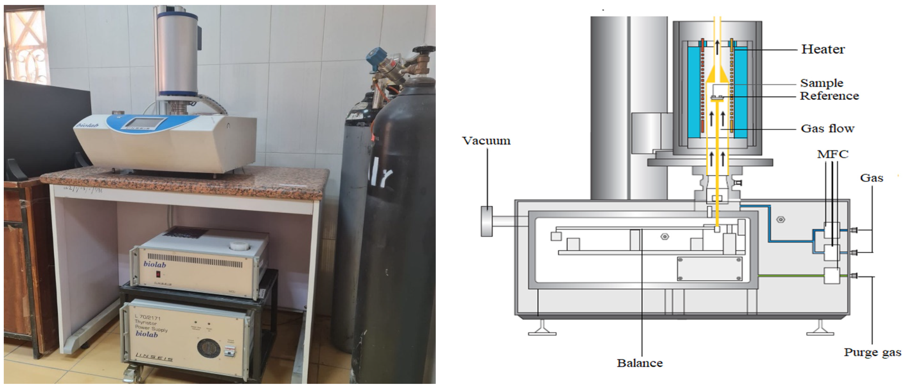
Thermogravimetric analysis (TGA) is a method used to determine a material’s thermal stability, moisture content, and volatile components by observing its weight change during constant heating. This study utilized a Linseis STA PT 1600 instrument for TGA analysis. Specifically, 12 mg of AR and 14.5 mg of AB were placed in the instrument’s holder, and Nitrogen gas was used to purge the system at a flow rate of 1 mL/min. The sample was heated to 900 °C at a rate of 5 °C/min and then cooled at a rate of 20 °C/min. Figure 2 displays the instrument’s pictorial view and its operational principle.

2.3.3. Contact Time Measurements

This method qualitatively assesses the hydrophilic or hydrophobic nature of an adsorbent surface. The technique involves placing a small water droplet on the surface and observing its behaviour, which is characterised by the contact angle between the water and the material surface.

3. Results and Discussion

3.1. FTIR Analysis of Adsorbents

The FTIR spectra of ABs before and after oil adsorption are presented in Figure 3 and Figure 4, respectively. The spectra reveal that the peaks observed in both spectra are in the same region, but an increase in peak intensity is observed after adsorption. Table 1 displays the wavenumber, location, and type of functional groups before and after adsorption.
The FTIR spectrum of AB adsorbents before and after oil adsorption is presented in Figure 3 and Figure 4, respectively. Table 1 provides information about the wavenumber, functional group type, and location before and after adsorption. The broad bands observed in the region of 3200–3500 cm−1 in both spectra indicate the presence of hydroxyl groups O-H. The presence of a C–H expansion of alkenes is shown by the two peaks in the region of 2850–3000 cm−1. The peak observed in the range of 1550–1650 cm−1 may be due to adsorbed water’s bending vibration and aromatic groups’ presence. The peak represents the N-O asymmetric stretching vibration of nitro compounds spotted in the band in the range of 1470–1550 cm−1. The C-C stretching vibration of aromatic groups is indicated by the band in the range of 1400–1500 cm−1. Lastly, the two peaks identified in the region of 1020–1250 cm−1 correspond to the C-N stretching vibration of the aliphatic amines group. From Figure 3 and Figure 4, the location range of the peaks did not change. An expansion in their size after adsorption was observed in both spectra. This phenomenon can be attributed to the physical adsorption process used to remove the oil with AB adsorbent.
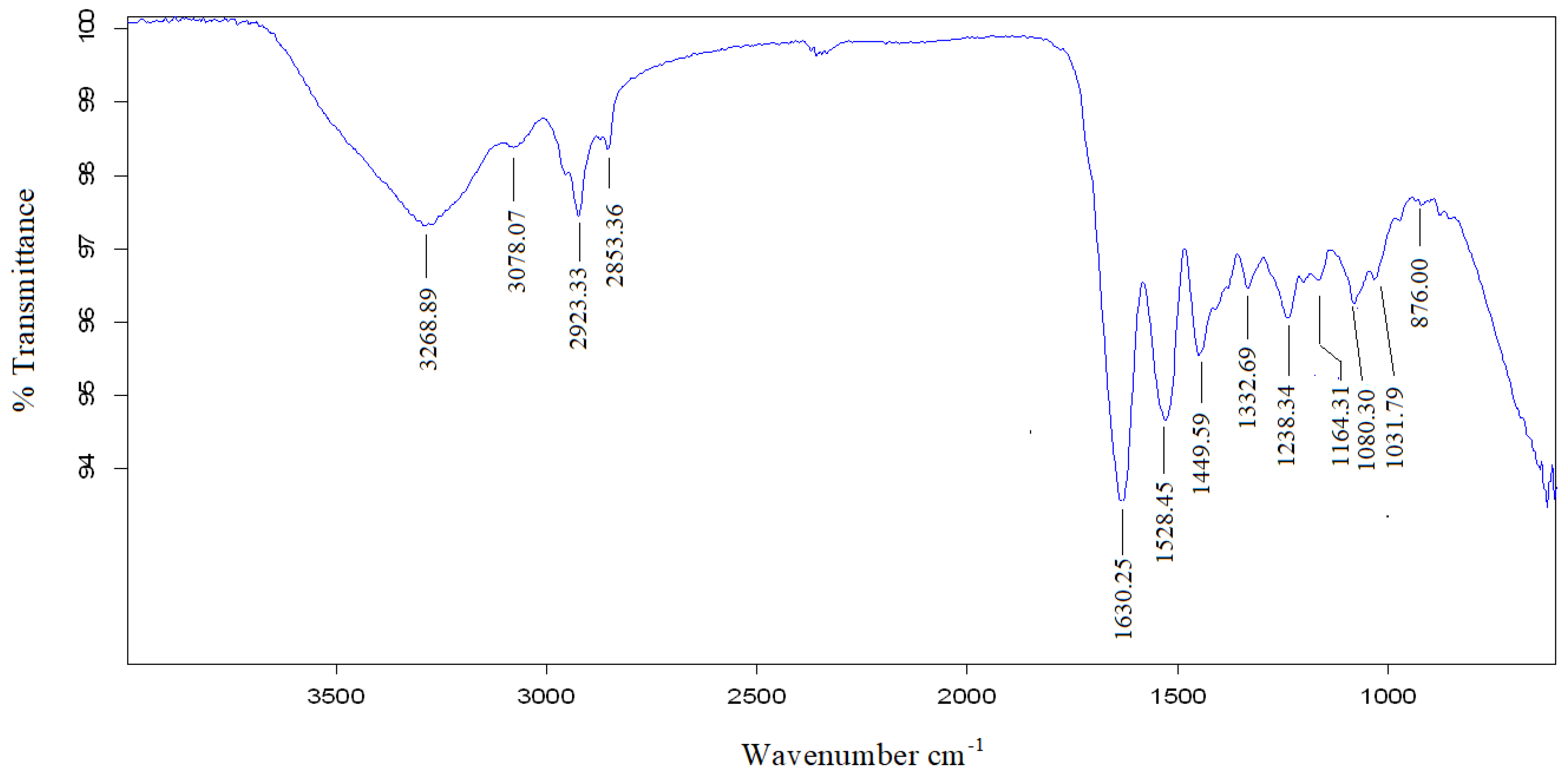
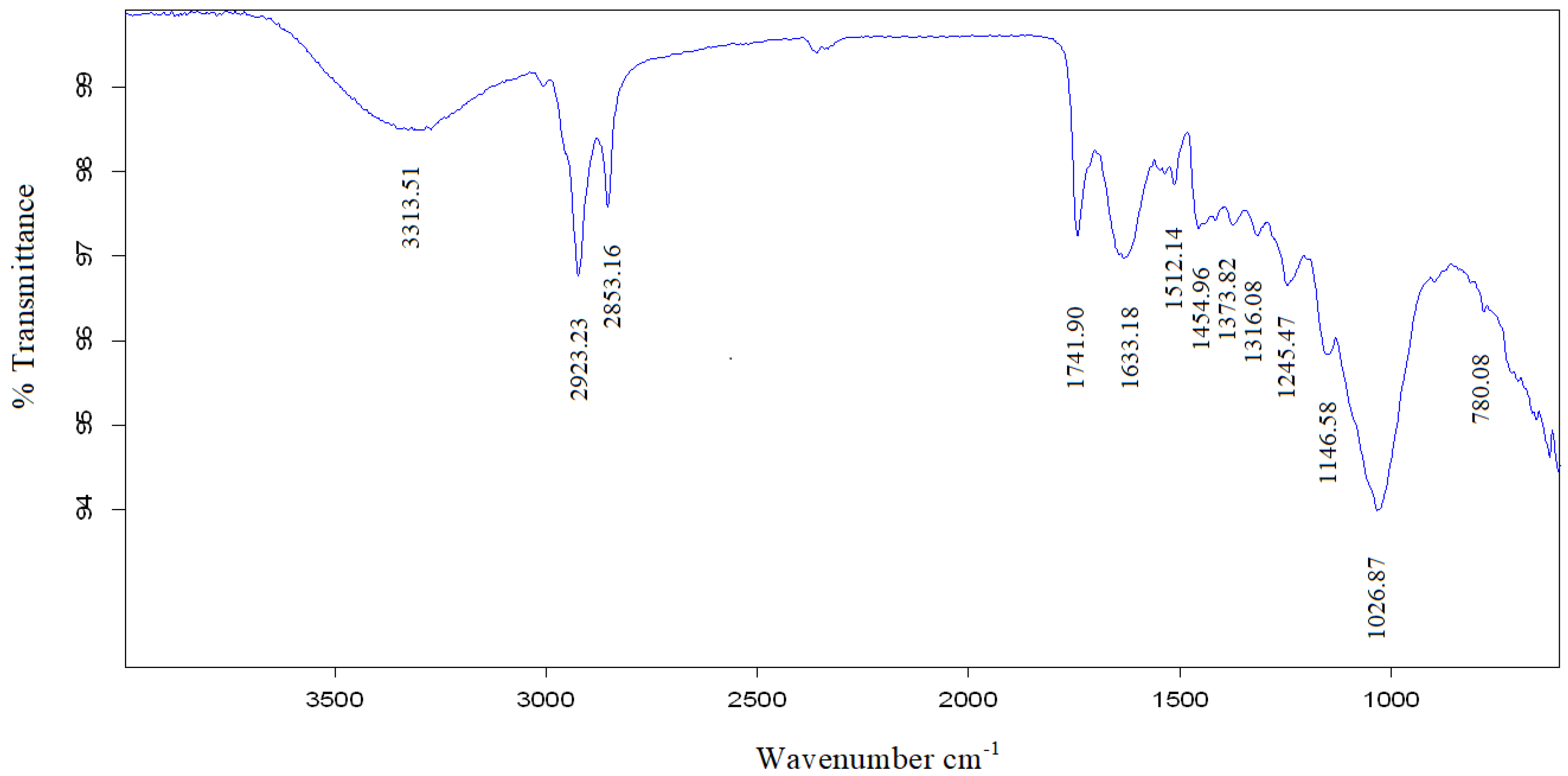
The FTIR spectrum of AR adsorbents before and after oil adsorption are shown in Figure 5 and Figure 6, respectively, and the wavenumber range, the vibration and the type of functional groups, are listed in Table 2.
The FTIR spectrum analysis of adsorption in Figure 5 and Figure 6 demonstrates a broad peak and a number of sharp peaks. These peaks occupy the same location range of wavenumber in both Figure 5 and Figure 6 but are different in size or percentage transmittance. The broad peak at the wavenumber range of 3200–3500 cm−1 indicated the presence of O-H stretching vibration of alcohols and phenols on the surface of the adsorbent. The two sharp band peaks at the wavenumber range 2850–3000 cm−1 correspond to the presence of C-H stretching vibration of alkanes groups. A sharp peak observed in the wavenumber range 1690–1760 cm−1 was attributed to the C=O stretching vibration of carbonyl and carboxylic acid. The peak present in the wavenumber ranges 1630–1680 cm−1, corresponding to the C=C bending of amides. Finally, the peak in the wavenumber of 1032.78 and 1026.87 cm−1 in Figure 5 and Figure 6, respectively, is for C-N stretching of aliphatic amine.

3.2. Thermogravimetric Analysis (TGA)

The thermal stability of the two adsorbents, ARs and ABs, was investigated using TGA analysis. Additionally, the results generated were captured and reported accordingly, as shown in Figure 7 and Figure 8 for ARs and ABs, respectively. The TGA of Figure 7 shows mass change at a temperature range of 0–200 °C due to the loss of moisture content in the AR. Between 200 and 500 °C, there is a sharp drop in mass, which is most likely due to the loss and decomposition of the volatile component. The curve is straight at temperatures above 500 °C, indicating that only carbon remained at that temperature. In Figure 8, there is a change in mass from 0 °C to approximately 220 °C, corresponding to moisture content released from ABs. Between 220 and 550 °C a sharp decrease in mass and this could be due to the decomposition of organic matter. At 550 °C, there is no change in the mass with temperature [29,30].

3.3. Contact Angle Measurement

The hydrophilicity of an adsorbent’s surface can be qualitatively evaluated through the contact angle measurement. As seen in Figure 9 and Figure 10, the contact angle results before and after the adsorption process were both zero for both ARs and AB adsorbents. The contact angle was measured by placing a 5 µm water droplet on the adsorbent surface. A contact angle of zero indicates complete wetting of the surface. A low contact angle indicates good interaction between the liquid and solid surface, implying good surface wettability and adhesion [31].

3.4. Adsorbent Dose Impact

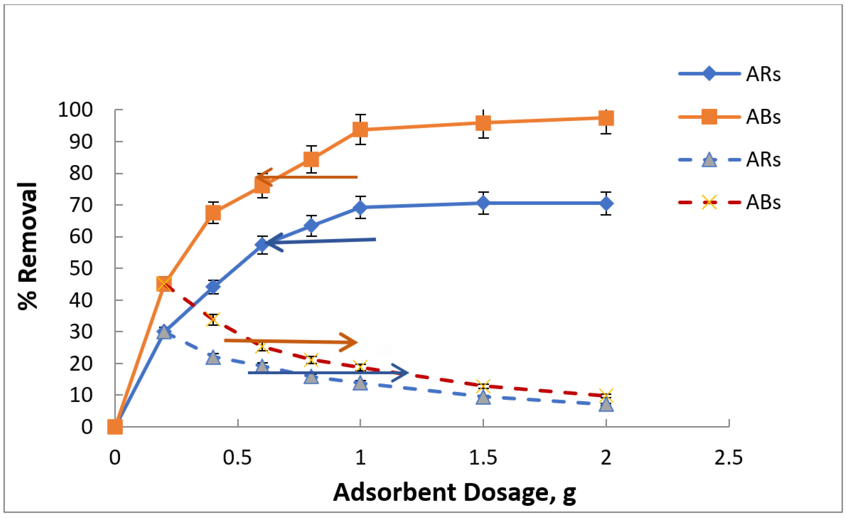
The effect of varying doses of two adsorbents (ABs and ARs) on the removal of oil from the water was investigated by utilizing different dosages ranging from 0.2 to 2 g. The findings revealed that increasing the adsorbent dose led to an increase in the percentage removal of oil and a decrease in the adsorption capacity of the adsorbent, as illustrated in Figure 11. The rise in the percentage removal of oil with the increase in the adsorbent dose is due to an increase in the number of active sorption sites available on the adsorbent’s surface. Furthermore, an increase in the adsorbent dose led to an increase in the number of unsaturated sites, which, in turn, caused lower adsorption capacity with an increase in the adsorbent dose. This observation aligns with the outcomes of earlier studies. [8,19,21,22].
The maximum adsorption capacities of ABs and ARs obtained were 45 and 30 mg/g, respectively, at 1 g of each adsorbent. The optimum percentage removal was 94% and 70% at 1 g of ABs and ARs, respectively. From these results, it can be concluded that AB adsorbent gives more efficiency than ARs for removing oil from water.

3.5. Impact of Oil Concentration

The impact of oil concentration in the oil–water mixture has been investigated, as shown in Figure 12. This study was conducted using different initial oil concentrations (200, 400, 600, 800, and 1000 mg/L), 1 g of ABs and AR adsorbents, 6.5 pH of the solution, 25 °C temperature, and 60 min contact time. The figure shows that the percentage removal of oil decreases with an increase in the initial concentration of oil for both adsorbents used. This can be explained by the fact that the surface of the adsorbent contains a limited number of adsorbent sites and, therefore, insufficient to accommodate the increase in oil concentration [20,21].
Table 3 highlights the removal efficiency and adsorption capacity some of the synthesised and natural adsorbents for oily water treatment.

3.6. Adsorption Isotherm

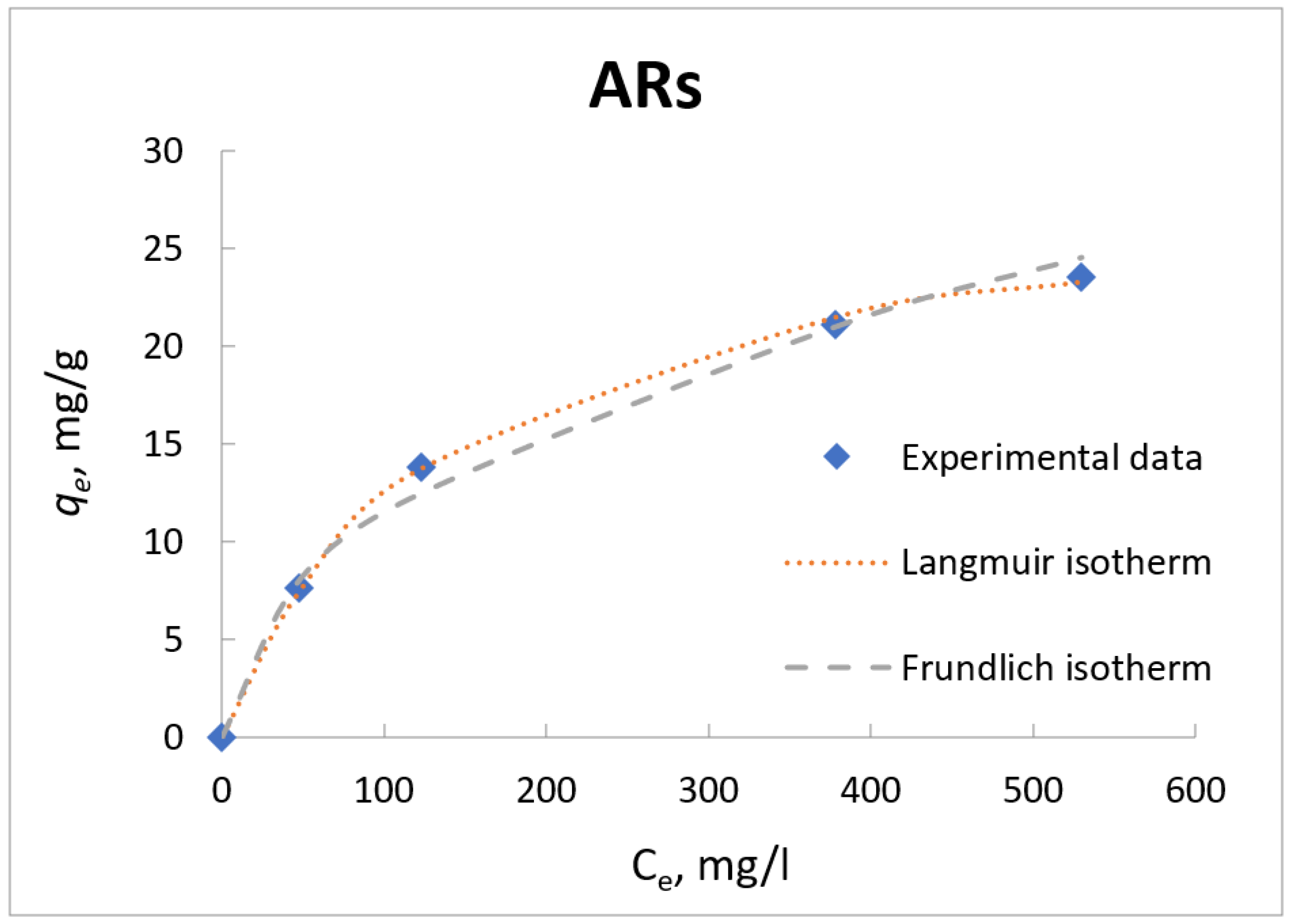
An adsorption isotherm is important to identify the equilibrium relationships between the adsorbate and adsorbent molecules. This relationship can be expressed graphically by plotting the adsorption capacity (qe) versus the concentration of the adsorbate remaining in the liquid phase (Ce) at equilibrium and at a constant temperature, as shown in Figure 13 and Figure 14. The experimental value of qe for adsorption of oil on the surface of the ABs and AR adsorbent was determined using Equation (1). From Figure 13 and Figure 14, it can be said that the adsorption capacity increased with increasing the initial concentration of the oil. The increase in the adsorption capacity was rapid at low oil concentrations, then converged and became almost constant due to reaching the equilibrium stage at high oil concentrations. The lower adsorption capacity at lower oil concentrations is due to the presence of an excess of unsaturated adsorption sites at the surface of the adsorbents. At higher concentrations of oil, the adsorption sites become saturated and reach their equilibrium stage.
The adsorption isotherm data in the present work was described using two common isotherm models, the Langmuir [32], and the Freundlich as shown in Figure 13 and Figure 14 for ARs and ABs, respectively.
The following equations, respectively, represent the non-linear form of Langmuir model (Equation (2)) and three linear forms of the Langmuir model (Equations (3)–(5)):
q e = q m   K L   C e 1 + K L   C e q e = V m C o C e
C e q e = 1 q m K L + 1 q m   C e ( Linear-1 )
1 q e = 1 q m K L 1 C e + 1 q m ( Linear-2 )
q e = q m q e K L C e ( Linear-3 )
where qm (mg/g) is the maximum amount of adsorption capacity to form a complete monolayer on the surface, and KL (L/mg) is the adsorption constant for the Langmuir isotherm.
The following equations, respectively, represent the non-linear and linear versions of the Freundlich equation:
q e = K f C e 1 n
l n q e = 1 n l n C e + l n K f
where Kf (mg/g) (L/mg)1/n and n are the Freundlich constants. Kf refers to the extent of the adsorption capacity, and n refers to the non-linearity of the relationships between the concentration of oil in the solution and the adsorption capacity and to the strength of the adsorption process [20,21].
The correlation coefficient of the fitting of the experimental data with Langmuir and Freundlich isotherm and their parameters are illustrated in Table 4.
The correlation coefficient R2 and Marquardt’s percent standard deviation, MPSD [33] as an error function was used to determine the compatibility of the experimental data with the isothermal models as given in equation 8. The values of R2 and MPSD are listed in Table 4.
M P S D = 100 1 n p i = 1 n q e , m e a s q e , c a l c q e , m e a s 2
The experimental data using AB adsorbent give good fitting with Langmuir and Freundlich model The correlation coefficient R2 of the Langmuir using the three linear forms are 0.9983, 0.9920 and 0.9752 for linear 1, linear 2 and linear 3, respectively, while the R2 of the Freundlich model is 0.9736.
The R2 for Langmuir is slightly higher than Freundlich, but the value of MPSD of the Langmuir model using three forms of its linear equations (3.2762, 4.0258, and 3.8978) is lower than that of the Freundlich model (5.3534) as shown in Table 4. The lower values of MPSD indicate that the adsorption of oil onto ABs can be described better by the Langmuir model. The experimental data using AR adsorbent gives good matching with the Langmuir model with R2 of 0.9991, 0.9998, and 0.9988 (using the three of linear Langmuir model) greater than for Freundlich model with R2 of 0.9797, and the value of MPSD of the Langmuir model (1.7490, 1.4910, and 1.5277) is lower than that of the Freundlich model (8.7582). The agreements of the experimental data with Langmuir isotherm for both adsorbents indicates that the adsorption process of oil onto ABs and ARs is carried out by forming a monolayer on the adsorbent surface, which contains a finite number of active sites. The value of Kf refers to the maximum adsorption capacity of the adsorbent, and n refers to the level of the non-linearity between the concentration of solute and the adsorption capacity [20,34] as: (1) If n < 1, the adsorption process is chemical; (2) if n = 1, the adsorption is linear; and (3) if n > 1 the adsorption is physical and it is favourable. In the present work, the value of Kf is 5.9038 and 1.3464 (mg/g)(L/mg)1/n for ABs and AR adsorbents, respectively, and the value of n is 2.7064 and 2.1450 for ABs and AR adsorbents, respectively. The higher values of Kf and n for ABs indicate that ABs are more favourable for the removal of oil because the adsorption process is physical. The feasibility of the adsorption process can be determined by using the separation factor RL [35,36]. The value of RL is calculated as:
R L = 1 1 + K L C o
where Co is the initial concentration of the oil and KL the Langmuir constant. The nature of the adsorption process can be determined based on the value of RL calculated as specified in Table 5.
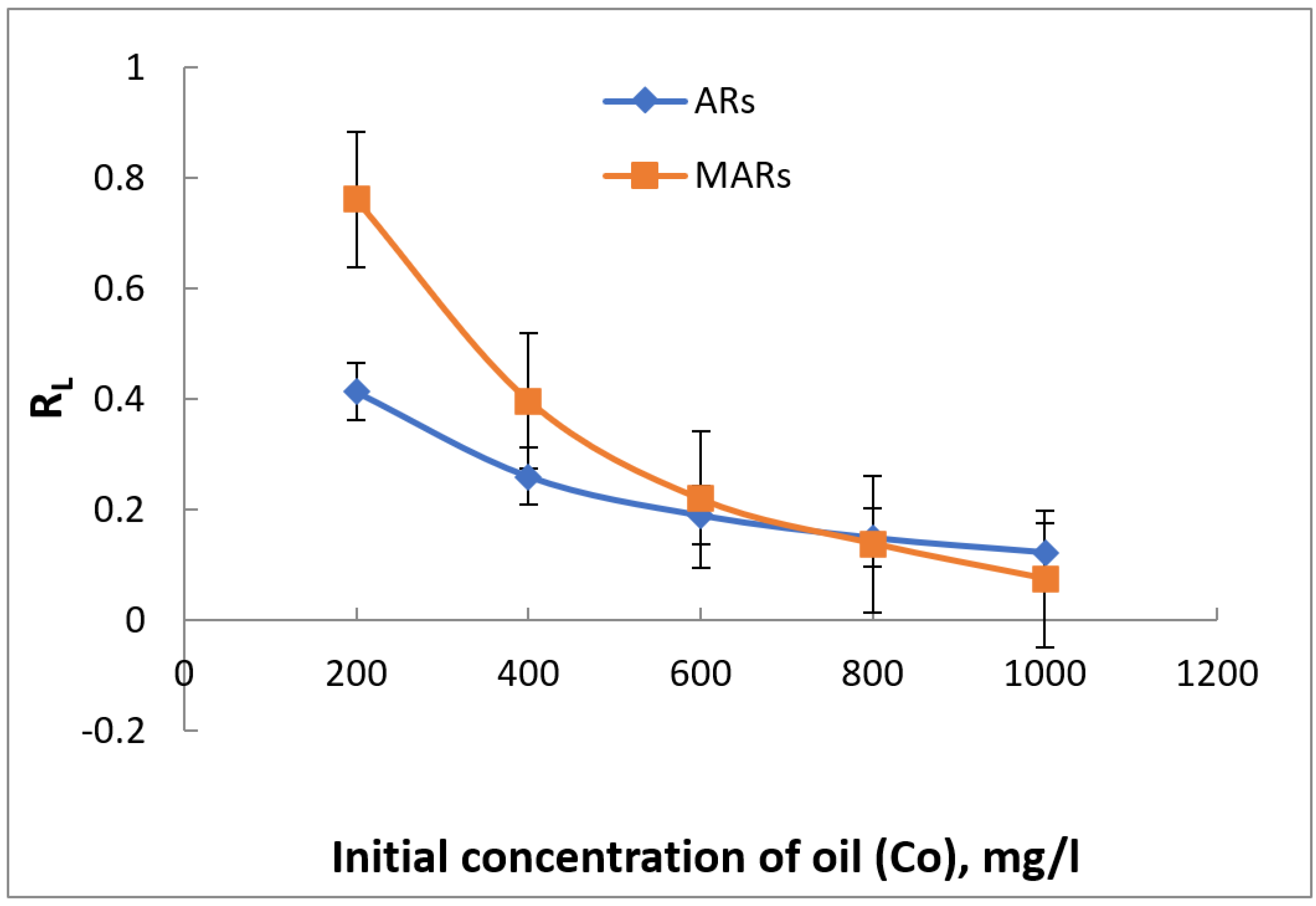
The values of RL at different initial concentrations as illustrated in Figure 15.
In the present work, the values of RL are greater than zero and less than one, indicating that the adsorption process is favourable by using ABs and ARs to remove oil from water.

3.7. Adsorption Kinetic Study

The investigation of adsorption kinetics is crucial in providing insight into the adsorption process, which encompasses the transfer of the solute from the aqueous solution to the external surface of the adsorbent, followed by diffusion within the adsorbent surface and binding to the active pores of the sorbents [21,37,38]. Assessing the rate at which the desired contaminant is absorbed by the adsorbent is a critical step in designing an efficient and scalable adsorption process, from laboratory to industrial scale (e.g., water treatment plant). To achieve this, experimental kinetic data must be analysed to match established kinetic models. Furthermore, these models are valuable in estimating other vital parameters such as activation energy, which can be determined using the Arrhenius equation [37,38]. The experimental investigation of adsorption kinetics involved monitoring the adsorption capacity of the adsorbent over time, as presented in Figure 16. The experiments were conducted at a temperature of 25 °C using 1g of adsorbent in 100 mL conical flasks, containing 50 mL of an oil–water mixture with a concentration of 400 mg/L and pH of 6.5. Six conical flasks, labeled as 1, 2, 3, 4, 5, and 6, were utilized to study the effect of various contact times of 5, 30, 60, 90, and 120 min, respectively. At the end of each time interval, the adsorbent was separated using a separating funnel, and the mixture was extracted with hexane and then analysed using atomic absorption spectrophotometry. Both adsorbents were tested using this methodology.
The kinetics of adsorption process is strongly influenced by time, which is an important parameter to describe the process. Figure 16 illustrates the trend of adsorption capacity for ABs and AR adsorbents as a function of time. It is evident from the figure that the adsorption capacity of both adsorbents increased with increasing time. The initial adsorption rate was fast, and the adsorption capacity reached a maximum within the first 30 min. However, a gradual decrease in the rate of adsorption capacity was observed between 30 and 60 min. After 60 min, the adsorption capacity became constant with the progression of time. This equilibrium state in adsorption capacity after 60 min may be attributed to the occurrence of a balance between the adsorption and desorption processes after the surface of the adsorbent material became saturated with oil.
There are several models used to describe the kinetic of the adsorption [38,39,40]. The most common models used are The pseudo-first-order model [41] and pseudo-second-order model [42].
The pseudo-first-order model is described by the following equation:
d q t d t = k 1 q e q t
where qe (mg/g) and qt (mg/g) are the sorption capacity at equilibrium and at time t, respectively, k1 (1/min) is the rate constant of pseudo-first order. The integrating of Equation (8) and applying the boundary conditions qt = 0 at t = 0 and qt = qt at t = t gives the following linear equation:
log q e q t = log q e k 1 2.303 t
The pseudo-second-order model is described by the following equation:
d q t d t = k 2 q e q t 2
where k2 (g/mg.min) is the rate constant of pseudo-second order. The integrating of Equation (12) and applying the boundary conditions qt = 0 at t = 0 and qt = qt at time t = t gives the following different for of linearized equations:
t q t = 1 k 2 q e 2 + 1 q e t ( Linear-1 )
1 q t = 1 k 2 q e 2 1 t + 1 q e ( Linear-2 )
q t = q e 1 k 2 q e q t ( Linear-3 )
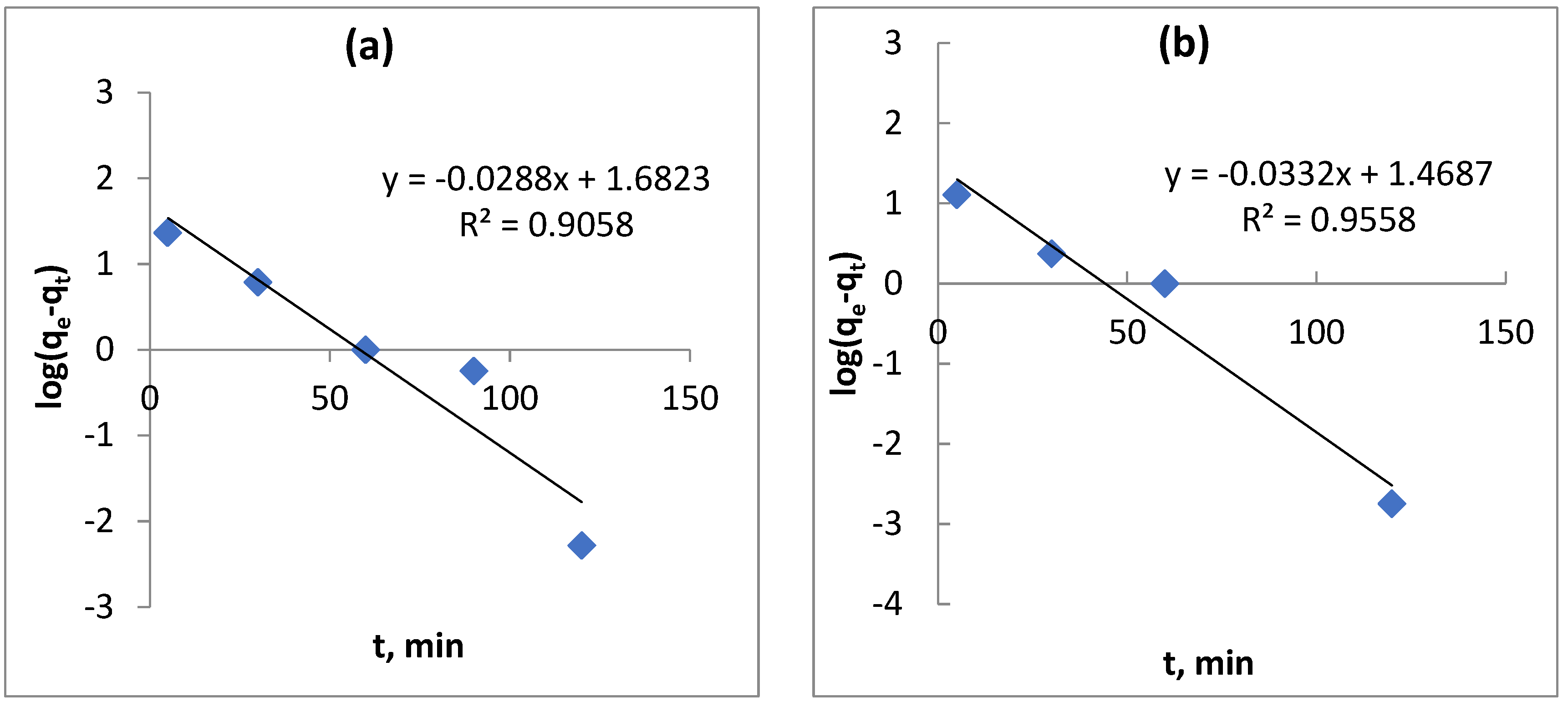
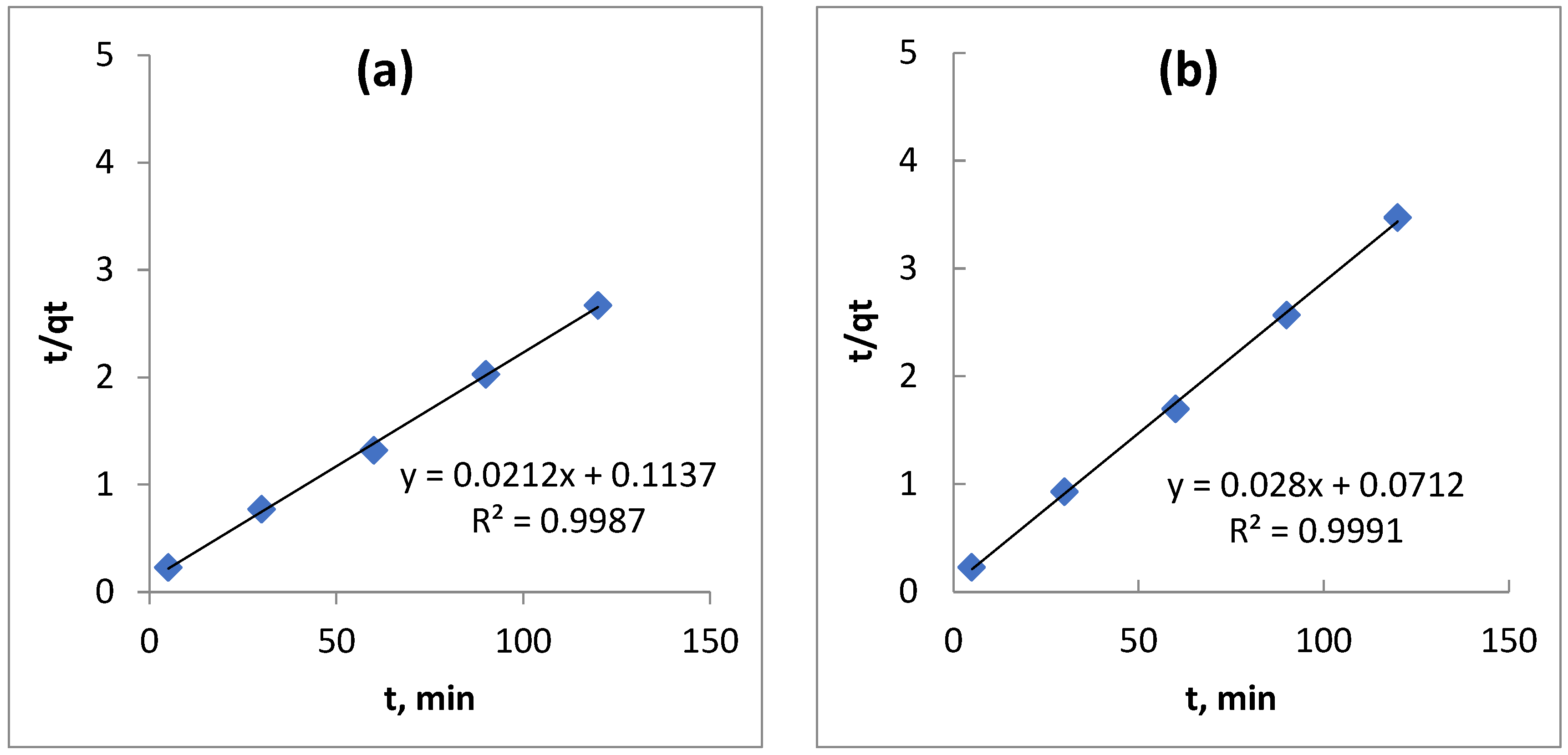
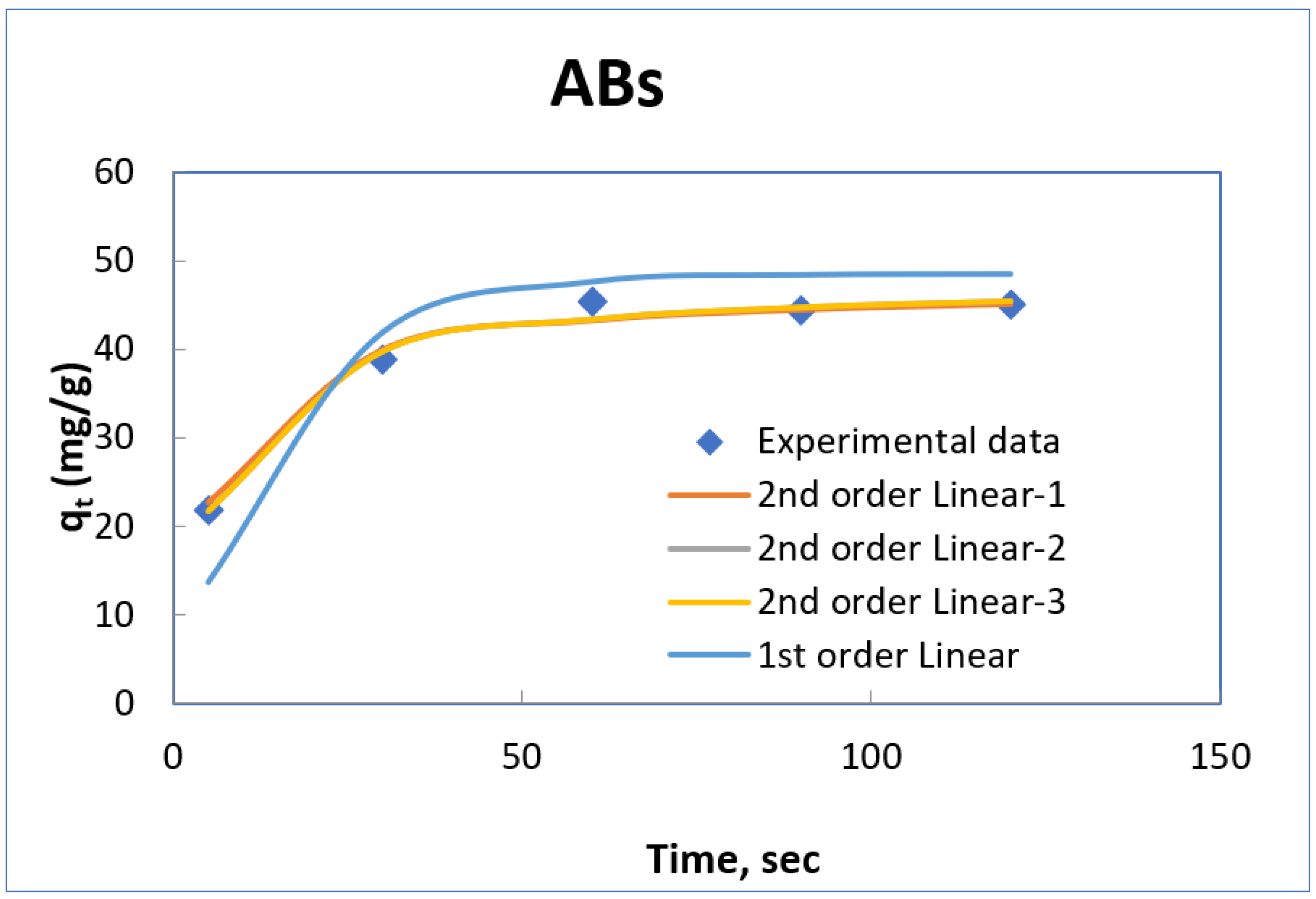
In the present adsorption, kinetics data of adsorption of oil onto ABs and ARs were analysed using pseudo-first-order (Equation (11)) and pseudo-second-order (Equation (13)) models, as shown in Figure 17 and Figure 18, respectively.
Table 6 presents the kinetics parameters and corresponding linear correlation coefficients that were calculated and recorded. The data demonstrate that the experimental results are best fitted by the pseudo-second-order kinetic model, with R2 values of 0.9987 and 0.9992 for ABs and ARs, respectively, as compared to the pseudo-first-order model. Thus, the adsorption process for oil removal using ABs and AR adsorbents does not conform to the pseudo-first-order kinetics model, but rather to the pseudo-second-order kinetics model. As per the pseudo-second-order kinetic model, the adsorption process involves chemisorption, which entails a chemical reaction that occurs by the formation of covalent bonds via electronic sharing or exchange between oil molecules and the adsorbent’s surface. These findings align with those of previous studies investigating the adsorption of oil from oil–water mixtures using banana pseudostem fibres [36] and adsorption of oil onto powder and flake chitosan [43].
The non linear and linearized for of first and second-order pseudo-kinetic models are presented in Figure 19 and Figure 20 for AB and AR adsorbents, respectively. These figures show that various linearized forms of pseudo-second-order equations give good and approximately the same fitting with experimental data.
The parameters of different linearized form of second-order pseudo-kinetic model are shown in Table 7.

3.8. BET Analsysis

Micropore, and external surface area have been measured for the tested adsorbents using BET analysis as shown in Table 8. Determining the surface area and pore size of the aniseed residue proved to be a challenging task.

3.9. Regeneration of Adsorbents

The process of regenerating adsorbent involves eliminating oil or impurities from spent adsorbent by utilizing a specific solvent that can remove oil and impurities. Regeneration is an environmentally and economically beneficial process since it decreases the volume of waste by reducing the disposal issues of spent adsorbents and the requirement for new adsorbents [44]. Various methods, such as biological, thermal, chemical, and photochemical methods [45], are utilized to desorb pollutants from the adsorbent. In this study, the regeneration process was conducted using hot water as a thermal method. The spent adsorbent was rinsed several times with hot water at 100 °C to release oil from spent adsorbent, and then the rinsed adsorbent was dried and used for oil adsorption to evaluate its oil removal capacity after regeneration. Multiple regeneration attempts were conducted after each adsorption process, and the regeneration conditions were 50 mL of 400 mg/L oil–water mixture and 2 g of adsorbent. Figure 21a,b demonstrate the regeneration process of AR and AB after four attempts. The results indicate that for AR, the percentage removal (%R) decreased from 93.6% for the first use to 69.9% for the fourth regeneration attempt, as depicted in Figure 21a. Similarly, for AB, the %R declined from 96.5% for the first use to 49.6% for the fourth regeneration attempt, as shown in Figure 21b.

4. Conclusions

The results of the experiment illustrate the potential of natural residues, namely animal bones (ABs) and anise residues (ARs), to serve as adsorbents in the treatment of oily water through adsorption. The utilisation of natural waste as absorbent materials offers both economic and environmental benefits by utilizing a low-cost adsorbent and converting waste into useful materials, thereby reducing environmental issues. This research introduces AB and ARs as new sorbent materials for oily water treatment. The efficacy of these adsorbents in removing oil from water is found to be influenced by various factors, including adsorbent dosage, oil concentration, and contact time. The findings indicate that ABs exhibit higher oil removal capacity than ARs, with removal capacities of 45 and 30 mg/g for ABs and ARs, respectively, and percentage removal of 94% and 70% for ABs and ARs, respectively. Additionally, TGA analysis reveals that there is a sharp decrease in mass for AR between 200 and 500 °C, while for AB, this phenomenon occurs between 220 and 550 °C. This study expands to include kinetic and adsorption models for a more in-depth understanding of the adsorption mechanism. The Langmuir isotherm model provides an excellent fit for all experimental data on oil adsorption onto ABs and AR adsorbents, while the pseudo-second-order kinetics model is used to describe the adsorption model. According to the pseudo-second-order kinetic model, the adsorption process is chemisorption, which involves a chemical reaction through electronic sharing or exchange between oil molecules and the adsorbent’s surface. The regeneration study demonstrates that the percentage removal (%R) for AR decreases from 93.6% after the first use to 69.9% after the fourth regeneration attempt, while for AB, the %R decreases from 96.5% after the first use to 49.6% after the fourth regeneration attempt.

Author Contributions

Conceptualization, J.A.A.-N., S.T.A.-H. and I.M.R.F.; methodology, software, validation, J.A.A.-N., S.T.A.-H. and I.M.R.F.; formal analysis, investigation, resources, data curation, writing—original draft preparation, J.A.A.-N., D.B., T.L., S.T.A.-H. and I.M.R.F.; writing—review and editing, I.V., I.M.R.F., M.E.M.S.; project administration, funding acquisition, I.M.R.F., M.E.M.S. All authors have read and agreed to the published version of the manuscript.

Funding

This research was funded by University of Technology Sydney through Strategic Research Support funding with grant number [2200034].

Acknowledgments

We extend our sincere gratitude to the Chemical Engineering Department at the University of Technology in Baghdad, Iraq, for their invaluable support and provision of space and necessary facilities that enabled the successful completion of this work.

Conflicts of Interest

The authors declare no conflict of interest.

References

  1. Sulyman, M.; Sienkiewicz, M.; Haponiuk, J.; Zalewski, S. New Approach for Adsorptive Removal of Oil in Wastewater using Textile Fibers as Alternative Adsorbent. Acta Sci. Agric. 2018, 2, 32–37. [Google Scholar]
  2. Zamri, M.F.M.A.; Hasmady, S.; Akhiar, A.; Ideris, F.; Shamsuddin, A.H.; Mofijur, M.; Fattah, I.M.R.; Mahlia, T.M.I. A comprehensive review on anaerobic digestion of organic fraction of municipal solid waste. Renew. Sustain. Energy Rev. 2021, 137, 110637. [Google Scholar] [CrossRef]
  3. Samal, K.; Geed, S.R.; Mohanty, K. Chapter 23 - Hybrid biological processes for the treatment of oily wastewater. In Advances in Oil-Water Separation; Das, P., Manna, S., Pandey, J.K., Eds.; Elsevier: Amsterdam, The Netherlands, 2022; pp. 423–435. [Google Scholar]
  4. Cisterna-Osorio, P.; Arancibia-Avila, P. Comparison of Biodegradation of Fats and Oils by Activated Sludge on Experimental and Real Scales. Water 2019, 11, 1286. [Google Scholar] [CrossRef] [Green Version]
  5. Sherhan, B.Y.; Abbas, A.D.; Alsalhy, Q.F.; Abbas, T.K.; Mahdi, y.M.; Kareem, N.A.A.; Rashad, A.A.; Rashad, Z.W.; Shawkat, A.A. Produced Water Treatment Using Ultrafiltration and Nanofiltration Membranes. Al-Khwarizmi Eng. J. 2016, 12, 10–18. [Google Scholar]
  6. Alsulaili, A.D.F.; Asmaa, M. Oil removal from produced water by agriculture waste adsorbents. Int. J. Environ. Waste Manag. 2020, 25, 12–31. [Google Scholar] [CrossRef]
  7. Al-Zuhairi, F.K.; Azeez, R.; Mahdi, S.A.; Kadhim, W.A.; Al-Naamee, M.K. Removal oil from produced water by using adsorption method with adsorbent a Papyrus reeds. Eng. Technol. J. 2019, 37, 157–165. [Google Scholar] [CrossRef]
  8. Alaa El-Din, G.; Amer, A.A.; Malsh, G.; Hussein, M. Study on the use of banana peels for oil spill removal. Alex. Eng. J. 2018, 57, 2061–2068. [Google Scholar] [CrossRef]
  9. Maddah, Z.H.; Naife, T.M. Demulsification of Water in Iraqi Crude Oil Emulsion. J. Eng. 2019, 25, 37–46. [Google Scholar] [CrossRef] [Green Version]
  10. Piemonte, V.; Prisciandaro, M.; Mascis, L.; Di Paola, L.; Barba, D. Reverse osmosis membranes for treatment of produced water: A process analysis. Desalination Water Treat. 2015, 55, 565–574. [Google Scholar] [CrossRef]
  11. Ahmad, N.A.; Goh, P.S.; Abdul Karim, Z.; Ismail, A.F. Thin Film Composite Membrane for Oily Waste Water Treatment: Recent Advances and Challenges. Membranes 2018, 8, 86. [Google Scholar] [CrossRef] [Green Version]
  12. Jiménez, S.; Andreozzi, M.; Micó, M.M.; Álvarez, M.G.; Contreras, S. Produced water treatment by advanced oxidation processes. Sci. Total Environ. 2019, 666, 12–21. [Google Scholar] [CrossRef] [PubMed]
  13. Sellami, M.; Loudiyi, K.; Bellemharbet, K.; Djabbour, N. Electro-Coagulation Treatment and De-oiling of Wastewaters Arising from Petroleum Industries. J. Pet. Environ. Biotechnol. 2016, 7. [Google Scholar] [CrossRef] [Green Version]
  14. Xie, A.; Ladner, D.A.; Popat, S.C. Electrocoagulation-electroflotation for primary treatment of animal rendering wastewater to enable recovery of fats. Chem. Eng. J. 2022, 431, 133910. [Google Scholar] [CrossRef]
  15. Remedhan, S.T. Experimental Investigation of Thermodynamics, Kinetics, and Equilibrium of Nickel Ion Removal from Wastewater Using Zinc Oxide Nanoparticles as the Adsorbent. Eng. Technol. J. 2020, 38, 1047–1061. [Google Scholar] [CrossRef]
  16. Sabir, S. Approach of Cost-Effective Adsorbents for Oil Removal from Oily Water. Crit. Rev. Environ. Sci. Technol. 2015, 45, 1916–1945. [Google Scholar] [CrossRef]
  17. Tansel, B.; Pascual, B. Removal of emulsified fuel oils from brackish and pond water by dissolved air flotation with and without polyelectrolyte use: Pilot-scale investigation for estuarine and near shore applications. Chemosphere 2011, 85, 1182–1186. [Google Scholar] [CrossRef] [PubMed]
  18. Aliyu, U.M.; El-Nafaty, U.A.; Muhammad, I.M. Oil removal from crude oil polluted water using banana peel as sorbent in a packed column. J. Nat. Sci. Res. 2015, 5, 157–162. [Google Scholar]
  19. Muhammad, I.M.; El-Nafaty, U.A.; Surajudeen, A.; Makarfi, Y.I. Oil Removal from Produced Water Using Surfactant Modified Eggshell. In Proceedings of the 2015 4th International Conference on Environmental, Energy and Biotechnology (ICEEB 2015), Madrid, Spain, 15–16 June 2015; pp. 84–92. [Google Scholar]
  20. Sidik, S.M.; Jalil, A.A.; Triwahyono, S.; Adam, S.H.; Satar, M.A.H.; Hameed, B.H. Modified oil palm leaves adsorbent with enhanced hydrophobicity for crude oil removal. Chem. Eng. J. 2012, 203, 9–18. [Google Scholar] [CrossRef]
  21. Lutfee, T. Removal of Phenol From Aqueous Solution By Agriculture Waste. Eng. Technol. J. 2010, 28, 5938–5955. [Google Scholar]
  22. Benjamin Daniel, A.; Zahir, E.; Asghar, M.A. On the practicability of a new bio sorbent: Lasani sawdust and coconut coir for cleanup of oil spilled on water. Pet. Sci. Technol. 2019, 37, 1143–1154. [Google Scholar] [CrossRef]
  23. Onwuka, J.C.; Agbaji, E.B.; Ajibola, V.O.; Okibe, F.G. Treatment of crude oil-contaminated water with chemically modified natural fiber. Appl. Water Sci. 2018, 8, 86. [Google Scholar] [CrossRef] [Green Version]
  24. Pon-On, W.; Suntornsaratoon, P.; Charoenphandhu, N.; Thongbunchoo, J.; Krishnamra, N.; Tang, I.M. Hydroxyapatite from fish scale for potential use as bone scaffold or regenerative material. Mater. Sci. Eng. C 2016, 62, 183–189. [Google Scholar] [CrossRef] [PubMed]
  25. Ayyanar, C.B.; Marimuthu, K.; Gayathri, B.; Sankarrajan. Characterization and in vitro cytotoxicity evaluation of fish scale and seashell derived nano-hydroxyapatite high-density polyethylene composite. Polym. Polym. Compos. 2021, 29, 1534–1542. [Google Scholar] [CrossRef]
  26. Shojaii, A.; Abdollahi Fard, M. Review of Pharmacological Properties and Chemical Constituents of Pimpinella anisum. ISRN Pharm. 2012, 2012, 510795. [Google Scholar] [CrossRef] [Green Version]
  27. Singh, R.K.; Vishal, M.K.; Vishwakarma, R.K. Moisture Dependent Physical Properties of Anise Seeds. Int. J. Food Process. Technol. 2015, 2, 39–45. [Google Scholar]
  28. Katime, I.; Parada, L.; Meaurio, E.; Cesteros, L. Recent research developments in hydrogen bonding in polymer blends by Fourier transform infrared spectroscopy (FTIR) and calorimetry. Recent Res. Devel. Polym. Sci. 1997, 1, 91–107. [Google Scholar]
  29. Yahya, M.D.; Muhammed, I.B.; Obayomi, K.S.; Olugbenga, A.G.; Abdullahi, U.B. Optimization of fixed bed column process for removal of Fe(II) and Pb(II) ions from thermal power plant effluent using NaoH-rice husk ash and Spirogyra. Sci. Afr. 2020, 10, e00649. [Google Scholar] [CrossRef]
  30. Alias, N.; Ibrahim, N.; Hamid, M.K.A.; Hasbullah, H.; Ali, R.R.; Sadikin, A.N.; Asli, U.A. Thermogravimetric analysis of rice husk and coconut pulp for potential biofuel production by flash pyrolysis. Malays. J. Anal. Sci. 2014, 18, 705–710. [Google Scholar]
  31. Jansson, I.; García-García, F.J.; Sánchez, B.; Suárez, S. Key factors to develop hybrid photoactive materials based on mesoporous carbon/TiO2 for removal of volatile organic compounds in air streams. Appl. Catal. A Gen. 2021, 623, 118281. [Google Scholar] [CrossRef]
  32. Langmuir, I. The Constitution and Fundamental Properties of Solids and Liquids. Part I. Solids. J. Am. Chem. Soc. 1916, 38, 2221–2295. [Google Scholar] [CrossRef] [Green Version]
  33. Didar, Z. Removal of impurities from waste oil using eggshell and its active carbon. J. Adv. Environ. Health Res. 2017, 5, 123–130. [Google Scholar] [CrossRef]
  34. Senthil Kumar, P.; Ramalingam, S.; Senthamarai, C.; Niranjanaa, M.; Vijayalakshmi, P.; Sivanesan, S. Adsorption of dye from aqueous solution by cashew nut shell: Studies on equilibrium isotherm, kinetics and thermodynamics of interactions. Desalination 2010, 261, 52–60. [Google Scholar] [CrossRef]
  35. Okiel, K.; El-Sayed, M.; El-Kady, M.Y. Treatment of oil–water emulsions by adsorption onto activated carbon, bentonite and deposited carbon. Egypt. J. Pet. 2011, 20, 9–15. [Google Scholar] [CrossRef] [Green Version]
  36. Husin, N.I.; Wahab, N.A.A.; Isa, N.; Boudville, R. Sorption Equilibrium and Kinetics of Oil from Aqueous Solution Using Banana Pseudostem Fibers. In Proceedings of the 2011 International Conference on Environment and Industrial Innovation (ICEII 2011), Kuala Lumpur, Malaysia, 4–5 June 2011; pp. 177–182. [Google Scholar]
  37. Podder, M.S.; Majumder, C.B. Bacteria immobilization on neem leaves/MnFe2O4 composite surface for removal of As(III) and As(V) from wastewater. Arab. J. Chem. 2019, 12, 3263–3288. [Google Scholar] [CrossRef]
  38. Lima, E.C.; Sher, F.; Guleria, A.; Saeb, M.R.; Anastopoulos, I.; Tran, H.N.; Hosseini-Bandegharaei, A. Is one performing the treatment data of adsorption kinetics correctly? J. Environ. Chem. Eng. 2021, 9, 104813. [Google Scholar] [CrossRef]
  39. Tan, K.L.; Hameed, B.H. Insight into the adsorption kinetics models for the removal of contaminants from aqueous solutions. J. Taiwan Inst. Chem. Eng. 2017, 74, 25–48. [Google Scholar] [CrossRef]
  40. Tran, H.N.; You, S.-J.; Hosseini-Bandegharaei, A.; Chao, H.-P. Mistakes and inconsistencies regarding adsorption of contaminants from aqueous solutions: A critical review. Water Res. 2017, 120, 88–116. [Google Scholar] [CrossRef]
  41. Lagergren, S. Zur Theorie der Sogenannten Adsorption Gelöster Stoffe. K. Sven. Vetensk. Handl. 1898, 24, 1–39. [Google Scholar]
  42. Blanchard, G.; Maunaye, M.; Martin, G. Removal of heavy metals from waters by means of natural zeolites. Water Res. 1984, 18, 1501–1507. [Google Scholar] [CrossRef]
  43. Ahmad, A.L.; Sumathi, S.; Hameed, B.H. Chitosan: A Natural Biopolymer for the Adsorption of Residue Oil from Oily Wastewater. Adsorpt. Sci. Technol. 2004, 22, 75–88. [Google Scholar] [CrossRef]
  44. Omorogie, M.O.; Babalola, J.O.; Unuabonah, E.I. Regeneration strategies for spent solid matrices used in adsorption of organic pollutants from surface water: A critical review. Desalination Water Treat. 2016, 57, 518–544. [Google Scholar] [CrossRef]
  45. Kow, S.-H.; Fahmi, M.R.; Abidin, C.Z.A.; Ong, S.-A.; Ibrahim, N. Regeneration of spent activated carbon from industrial application by NaOH solution and hot water. Desalination Water Treat. 2016, 57, 29137–29142. [Google Scholar] [CrossRef]
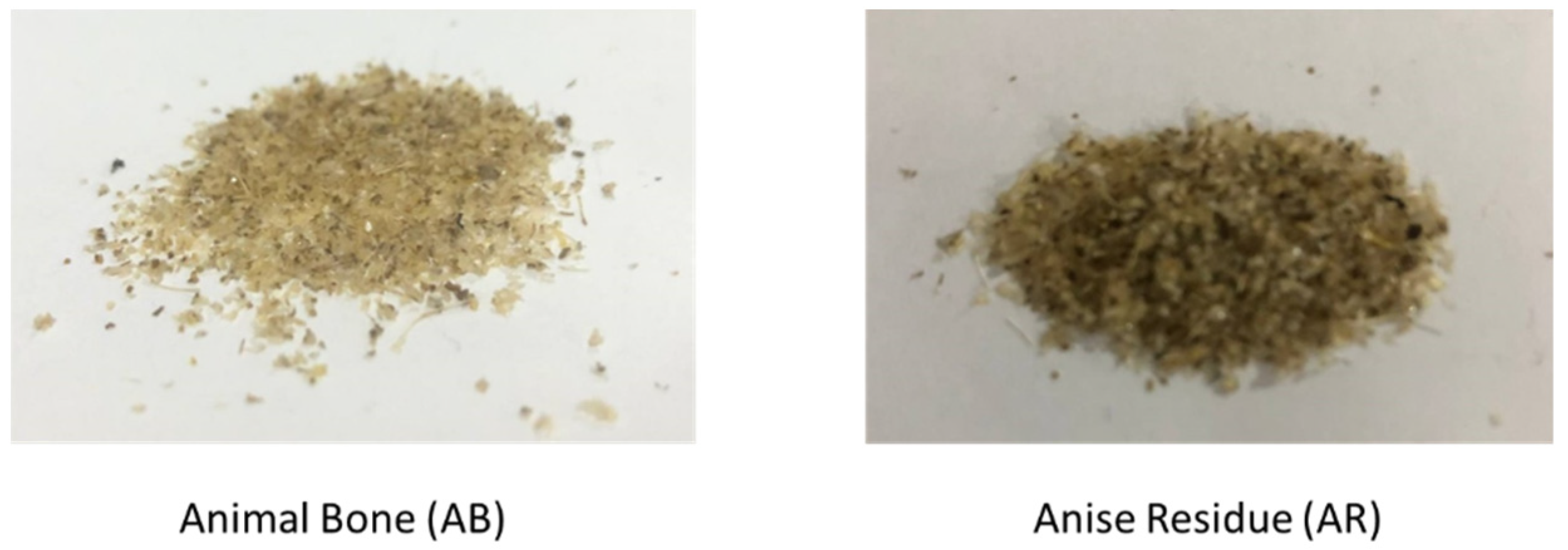
Figure 1. Visual representation of the adsorbent materials used: animal bone (AB) and anise residue (AR).
Water 15 01186 g001
Figure 2. Pictorial view and working principle of the TGA instrument used.
Water 15 01186 g002
Figure 3. FTIR spectrum for ABs before adsorption of oil.
Water 15 01186 g003
Figure 4. FTIR spectrum for ABs after adsorption of oil.
Water 15 01186 g004
Figure 5. FTIR spectrum for AR adsorbents before adsorption of oil.
Water 15 01186 g005
Figure 6. FTIR spectrum for AR adsorbents after adsorption of oil.
Water 15 01186 g006
Figure 7. TGA analysis of ARs.
Water 15 01186 g007
Figure 8. TGA analysis of ABs.
Water 15 01186 g008
Figure 9. Contact angle for AR adsorbent: (a) before adsorption; (b) after adsorption.
Water 15 01186 g009
Figure 10. Contact angle for AB adsorbent: (a) before adsorption; (b) after adsorption.
Water 15 01186 g010
Figure 11. The impact of adsorbent dosage on the adsorption of oil onto adsorbent (400 mg/L oil–water solution, pH 6.5, Temp. 25 °C, 60 min).
Water 15 01186 g011
Figure 12. The impact of initial concentration of oil on the percentage of oil onto ( ABs and ARs (1 g adsorbent, pH 6.5, Temp. 25 °C, 60 min).
Water 15 01186 g012
Figure 13. Adsorption isotherm for removal of oil onto AR adsorbent (1g ARs, pH 6.5, Temp.25 °C, 60 min).
Water 15 01186 g013
Figure 14. Adsorption isotherm for removal of oil onto AB adsorbent (1g ABs, pH 6.5, Temp. 25 °C, 60 min).
Water 15 01186 g014
Figure 15. The values of separation factor RL at different initial concentrations of oil for the ABs and AR adsorbents.
Water 15 01186 g015
Figure 16. The effect of contact time on the adsorption capacity of oil onto AB adsorbent (1 g ABs, pH 6.5, Temp. 25 °C).
Water 15 01186 g016
Figure 17. The pseudo-first-order kinetics model for adsorption of oil onto adsorbents: (a) ABs and (b) ARs (1g adsorbents, pH 6.5, Temp. 25 °C).
Water 15 01186 g017
Figure 18. The pseudo-Second-order kinetics model for adsorption of oil onto adsorbents: (a) ABs and (b) AR adsorbent (1g adsorbents, pH 6.5, Temp. 25 °C).
Water 15 01186 g018
Figure 19. The nonlinear and linearized form of first and second-order kinetics model for adsorption of oil onto ABs.
Water 15 01186 g019
Figure 20. The nonlinear and linearized form of first and second-order kinetics model for adsorption of oil onto ARs.
Water 15 01186 g020
Figure 21. Regeneration of (a) AR adsorbent and (b) AB adsorbent.
Water 15 01186 g021
Table 1. FTIR spectrum of AB adsorbents before and after the adsorption process of oil.
Wavenumber cm−1Wavenumber
Range cm−1
VibrationFunctional Group Present
BeforeAfter
3305.63268.893200–2500O-H StretchingAlcohol, phenols,
Carboxylic acid
3078.053078.07
2929.822923.332850–3000C-H StretchingAlkenes
2858.092853.36
1631.901630.251550–1650C=C StretchingAromatiAB
1519.451528.451475–1550N-O asymmetric stretchingNitro compounds
1446.451449.591400–1500C-C StretchingAromatiAB
1334.221332.691290–1400N-O StretchingNitro compounds
1235.78138.341000–1320C-O StretchingAlcohols, carboxylic acids, esters, ethers
1156.561164.311150–1300C-H wag (-CH2X) StretchingAlkyl halides
1081.961080.301250–1020C-N StretchingAliphatic amines
1028.301031.79
874.36876.00910–665N-H wag StretchingPrimary, and secondary amines
Table 2. FTIR spectrum of ASs adsorbents before and after adsorption process of oil.
Wavenumber cm−1Wavenumber Range cm−1VibrationGroup Present
BeforeAfter
3341.533313.513200–3500O-H stretching, H bond Alcohol, phenols
2923.482923.232850–3000C-H stretchingAlkanes
2853.322853.16
1744.791741.901690–1760C=O stretchingCarbonyl, carboxylic acid
1643.151633.181630–1680C=O stretchingAmides
1511.491512.141475–1550N-O symmetric stretchingNitro compounds
1456.411454.961450–1470C-H bendingAlkanes
1376.51373.821290–1400N-O stretchingNitro compounds
1318.921316.081000–1320C-O stretchingAlcohols, carboxylic acids, esters, ethers
1244.641245.471150–1300 mC-H wag (-CH2X) Alkyl halides
1146.181146.581250–1020C-N stretchingAliphatic amines
1032.781026.871250–1020C-N stretchingAliphatic amine
721.70780.08910–665N-H wag StretchingPrimary, secondary amines
Table 3. Synthesised and natural adsorbents for oily water treatment.
Adsorbent Adsorbate%Removalqe (mg/g)Ref
Textile fiber (TF) Oil95.24400[1]
Walnut shells and date pitsOil80 and 87-[6]
Papyrus reedOil94.5229.726[6]
Banana peelOil97.45 [18]
EggshellOil100108.69[19]
Modified oil palm leaves (OPL)Oil-1176[20]
SawdustOil-1282[22]
Coconut coirOil-360[22]
Anise residuesOil7030Present work
Animal boneOil9445Present work
Table 4. Correlation coefficient and isotherm parameter values of different isotherm models.
AdsorbentsIsotherm ModelIsotherm Parameter
SymbolUnitValues
ABs LangmuirLinear-1qmmg/g48.0769
KLL/mg0.0244
R2-------0.9983
MPSD-------3.2762
Linear-2qmmg/g46.5116
KLL/mg0.0267
R2-------0.9920
MPSD-------4.0258
Linear-3qmmg/g47.121
KLL/mg0.0258
R2-------0.9752
MPSD-------3.8978
Freundlich Kf(mg/g)(L/mg)1/n5.9038
n--------2.7064
R2--------0.9736
MPSD-------5.3534
ARs LangmuirLinear-1qmmg/g29.4985
KLL/mg0.0071
R2-----0.9991
MPSD-----1.7490
Linear-2qmmg/g29.1545
KLL/mg0.0073
R2-----0.9998
MPSD-----1.4910
Linear-3qmmg/g29.395
KLL/mg0.0072
R2-----0.9988
MPSD-----1.5277
FreundlichKf(mg/g)(L/mg)1/n1.3464
n-----2.1450
R2-----0.9797
MPSD-----8.7582
Table 5. The nature of the adsorption process.
RL Value Adsorption Nature
RL > 1Unfavourable
RL = 1Linear
0 < RL < 1Favourable
RL = 0Irreversible
Table 6. The parameter of kinetic models and correlation coefficient.
Pseudo-First OrderPseudo-Second Order
Adsorbentqe
mg/g
k1
min−1
R2qe
mg/g
k2
mg/g.min
R2
ABs48.54000.06660.904547.16980.003950.9987
ARs29.42390.07650.955835.46100.01120.9992
Table 7. The parameters of the pseudo-second-order of kinetic models using different linearized form.
Pseudo-Second Order
Adsorbent qe
mg/g
k2
mg/g.min
R2
ABsLinear-147.16980.003950.9987
Linear-247.61900.003520.9965
Linear-347.7510.003490.9861
ARsLinear-135.71430.01120.9992
Linear-236.23190.008290.9995
Linear-336.1690.00830.9861
Table 8. Surface area, pore volume and pore size of both adsorbents.
AdsorbentSurface Area (Micropore Surface Area), m2/gPore Volume (Micropore Volume), cm3/ gPore Size (nm)Particle Size (mm)
Anise Residue (AR)----0.00115------0.6
Animal Bond (AB)5.53890.0054773.955340.6
Disclaimer/Publisher’s Note: The statements, opinions and data contained in all publications are solely those of the individual author(s) and contributor(s) and not of MDPI and/or the editor(s). MDPI and/or the editor(s) disclaim responsibility for any injury to people or property resulting from any ideas, methods, instructions or products referred to in the content.