Article

Quantifying the Nitrogen-Removal Performance of a Constructed Wetland Dominated by Diffuse Agricultural Groundwater Inflows Using a Linked Catchment–Wetland Model

National Institute of Water and Atmospheric Research (NIWA), Hamilton 3216, New Zealand
*
Author to whom correspondence should be addressed.
Water 2023, 15(9), 1689; https://doi.org/10.3390/w15091689
Submission received: 9 March 2023 / Revised: 14 April 2023 / Accepted: 21 April 2023 / Published: 26 April 2023
(This article belongs to the Special Issue Advances in Engineered Wetlands for Treating Agricultural Runoff)

Abstract

:
Nitrogen loading from diffuse agricultural sources is a major water-quality problem worldwide. Constructed wetlands have been increasingly used to treat runoff and drainage from agricultural lands. However, the diffuse nature of nitrogen loading from farmlands often makes it challenging to trace flow pathways and measure the direct input loading to wetlands, and assess their nutrient-reduction performance. The Owl Farm wetland, Cambridge, New Zealand, receives inputs mainly from a subsurface drain and groundwater seepage. As it was not possible to directly measure wetland inflows, we used the Soil and Water Assessment Tool (SWAT) to estimate and partition the wetland inflow and nitrogen loading from the drain and seepage. A dynamic first-order tanks-in-series wetland model was linked with SWAT to evaluate the wetland capacity for nitrogen removal over a four-year period. The linked catchment–wetland model could simulate flow and nitrate load at the wetland outlet reasonably well with a Nash–Sutcliffe efficiency (NSE) of 0.7 and 0.76, respectively, suggesting that it provides a good representation of the hydrological and nitrogen processes in the upland catchment and the constructed wetland. We used two approaches, a mixed measurement-and-modelling-based approach and a process-based modelling approach to estimate the wetland efficiency of nitrogen removal. In both approaches, we found that the percentage load removal for nitrate-N and total N was related exponentially to the wetland outflow rate. Based on the process-based model estimates, the Owl Farm constructed wetland is very effective in removing nitrate-N with annual estimates of 55–80% (average 61%) removal. However, this capacity is very dynamic depending on the inflow from the catchment. The removal efficiency is very high at low flow and reduces when flow increases but is still maintained at around 20–40% during higher-flow periods. However, actual nitrogen-load removal in the wetland is greatest during high-flow periods when input loads are elevated. This study illustrates how a linked catchment–wetland modelling approach can be used to partition and quantify diffuse nitrogen input loads into wetlands from different types of runoff and to evaluate their subsequent reduction rates. The tool is particularly useful for situations where diffuse groundwater inflows, which are difficult to measure, are important nutrient sources.

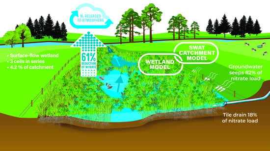
Graphical Abstract

1. Introduction

Agricultural diffuse source pollution is a major global problem causing significant environmental damage [1]. Excessive nutrient losses driven by drainage from agricultural lands are major causes of eutrophication in freshwater and coastal systems around the world [2,3,4,5], with climate change predicted to increase diffuse pollution impacts in many areas of the world [6]. Management of diffuse agricultural pollution is difficult to control because of its variability in time and space and its ubiquitous nature.
Constructed wetlands are increasingly being used as an edge-of-field approach to treat runoff and drainage from agricultural lands [7,8,9,10]. Wetlands can also provide other important ecosystem services, such as the mitigation of flood damage and the provision of natural habitats supporting biodiversity [7,11]. Constructed wetlands are able to effectively reduce downstream nutrient loads through natural water-treatment mechanisms, including sedimentation, microbial transformation processes such as denitrification, and uptake by vegetation. Although the ability of wetlands to remove nutrients is well established, the variability of diffuse runoff flows and associated contaminant loads makes it difficult to predict their performance under different climatic and landscape conditions [12,13].
The effectiveness of constructed wetlands is traditionally estimated based on measured flow and water quality concentrations at the inlets and outlets, e.g., Kadlec and Wallace [14]. However, where nutrient loads originate from diffuse sources, it may be difficult to trace flow pathways and measure the direct input loading to wetlands via variable surface and subsurface pathways [15]. Dynamic catchment models that have the capacity to continuously simulate the varying behaviour of complex processes in a catchment can be a useful technique to fill measurement gaps and improve estimates of the wetland N loading and removal performance from diffuse sources.
Computational models have been developed to simulate wetlands either at the individual wetland scale or at the catchment scale. At the wetland scale, some model examples include: MODFLOW, used to simulate the hydro-dynamics of the wetland induced by surface-flow and interactions with aquifers [16,17]; WETLAND [18] and Wetland Solute Transport Dynamics (WETSAND) [19], developed to simulate plant uptake and denitrification processes within a wetland; and SURFWET, a complex biokinetic model for surface-flow constructed wetlands [20]. In order to evaluate the effects of multiple wetlands at the catchment scale, a wetland module is usually coupled with a distributed catchment model or incorporated as a component of the model. For example, Arheimer and Wittgren [21] incorporated a simple and robust first-order model simulating nitrogen removal into a dynamic process-based catchment model, HBV-N. Hattermann et al. [22] extended the soil and water integrated model (SWIM) to simulate the groundwater table and retention processes in riparian zones and wetlands. The soil and water assessment tool (SWAT) [23] is the most common catchment model involved in wetland studies. SWAT has been applied to assess wetland effects on streamflow [24], to evaluate the impact of wetland restoration and losses on water quantity and water quality [25,26,27,28,29], and to identify optimal locations for wetland restoration to improve water quality and mitigate flood damage [30,31].
The objective of this study is to evaluate the effectiveness of a surface-flow constructed wetland in removing variable flows of nitrate-N from tile drainage and groundwater seepage from dairy pastures using a modelling approach. The Owl Farm constructed wetland, near Cambridge, New Zealand, is used as the case study and SWAT as the main modelling tool. Although SWAT does have a built-in wetland module to simulate wetland processes [32], it does not currently consider tile drainage as a wetland inflow, which limits its application for our study site, i.e., a wetland receiving drainage from a tile-drained pasture. Ikenberry et al. [33] recently incorporated new equations for wetland hydrology and nutrient removal into SWAT and applied them to two Iowa wetlands, receiving essentially point-sources of agricultural tile drainage. However, the Owl Farm wetland receives some tile drainage, but its predominant input is from groundwater seepage which occurs along its length rather than at a single inflow point. Therefore, a simple dynamic first-order tanks-in-series wetland model, similar to that outlined in Kadlec [34] and Tanner and Kadlec [13], was connected to SWAT to partition inputs from different flow paths into each cell of the wetland and assess the overall mass removal of nitrate-N.

2. Methodology

2.1. Study Site and Constructed Wetland

Owl Farm constructed wetland is a surface-flow wetland (also known as a free water surface wetland) located near Cambridge, North Island, New Zealand (Lat. −37.892001°, Long 175.420599°). The wetland area is 0.3 ha and receives runoff from a drainage area of 7.1 ha comprising grazed dairy pastures, resulting in a wetland-to-catchment ratio of 4.2%. The wetland, which was constructed and planted in 2016, has a maximum depth of 0.5 m and an average depth of 0.3 m. During the monitoring period (2017–2021), approximately 25% of the wetland area remained as open-water, with the remainder vegetated mainly with native Typha orientalis, Schoenoplectus tabernaemontani, and Cyperus ustilatus. The wetland is fringed with riparian plantings of Phormium tenax, Carex secta, Astroderia toetoe, Leptospermum scoparium, and mixed grasses.
The wetland is divided into three different-sized cells connected in series (Figure 1). The downstream cell receives inflow from its sub-catchment and the excess water volume from its direct upstream cell. The most upstream cell (cell 1) has the largest contributing area accounting for 77% of the catchment area (Table 1). The operational water depths of the four cells are approximately 0.3 m. The catchment inflow to cell 1 comes mostly from a single subsurface artificial drain and groundwater, while groundwater alone is the dominant contribution from the catchment to the other cells. The Owl Farm wetland is underlaid by a naturally occurring iron pan which limits water entering or exiting the wetland through the base. This means that water predominantly enters from the sides. The wetland receives inflow from the upslope catchment area which is active from late autumn to spring and normally dries over summer.

2.2. Water Sampling and Analysis

2.2.1. Flow Measurement

Continuous flow was measured at the outlet of wetland cell 3 every 5 min using a hydrostatic pressure sensor referenced to atmospheric pressure (Starflow 6526, Unidata, O’Connor, Western Australia) to measure the depth behind a V-notch weir set into the 300 mm PVC outlet pipe. Informed by a preliminary groundwater study (pers. comm. Dr. Roland Stenger, Lincoln Agritech, Hamilton, New Zealand), groundwater inflows were sampled in a well (screen depth 20 cm, diameter 20 cm) set into an obvious seepage area, 3 m from the edge of the wetland. The inflow from the tile drain was also measured on 5 occasions using a salt dilution technique as a check of the modelled flow estimates.

2.2.2. Water-Quality Measurement

Water-quality concentrations were measured at three locations: (i) at the tile drain where it enters wetland cell 1 (upstream tile), (ii) at a groundwater well in a seepage zone upslope of the edge of cell 1 (upstream well), and (iii) at the outlet of wetland cell 3 (downstream outlet).
Regular monthly, event, and high-frequency sampling were carried out to compare the flow and nitrogen concentrations entering and exiting the wetland as outlined in Table 2. Water-quality concentrations were measured at a monthly frequency by grab sampling at the three locations noted above. Six event samplings were also carried out during wet periods (winter–spring), providing a total of 126 downstream outlet samples. For some events, it was not possible to take water samples from the groundwater well and tile drain inflows; thus, the numbers of samples are around half those available for the outlet. Samples were returned to the laboratory on ice and analysed for total oxidised nitrogen (NOx-N; combined nitrate and nitrite, hereafter referred to as nitrate-N; automated cadmium reduction, flow injection analyser), ammonium-N (NH4-N; phenol/hypochlorite colorimetry) and total Kjeldahl nitrogen (TKN; sulphuric acid digestion with a copper sulphate catalyst followed by phenol/hypochlorite colorimetry) using standard methods [35]. Total nitrogen (TN) was calculated as the sum of TKN and NOx-N. In addition, high-frequency sampling (15 min interval) of nitrate-N was carried out at the downstream outlet using a calibrated photometric nitrate-N sensor (TriOS NICO 15S, Rastede, Germany).

2.3. Modelling Approach

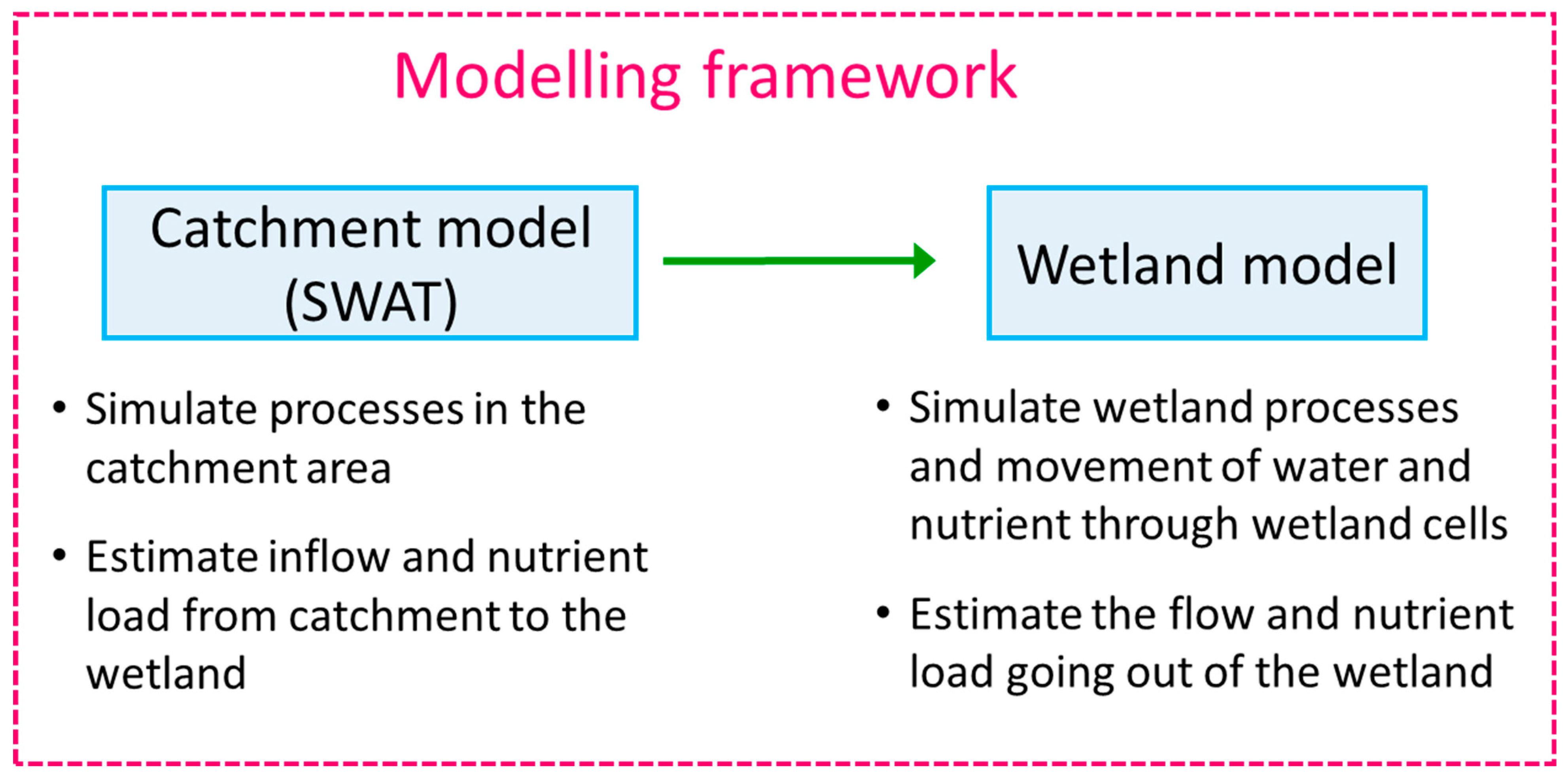
The modelling approach used in this study (Figure 2) is a linkage between the SWAT catchment model [23] and a dynamic first-order wetland nitrogen-removal model [34]. The catchment model simulates the catchment processes and estimates the different flow components (surface runoff, tile flow, and groundwater flow) and the nitrogen load associated with each flow component. These estimates are fed into the wetland model based on the simple water and mass balance approach used by Tanner and Kadlec [13] and Uuemaa et al. [36], which subsequently simulates the hydrology and first-order nitrogen removal during passage through the wetland cells (conceptualised as a series of completely-mixed tanks-in-series) and estimates the wetland outflow and nitrogen loads.

2.4. The SWAT Model

2.4.1. Brief Introduction to SWAT

SWAT is a dynamic, distributed, process-based catchment model that has been applied worldwide across a wide range of catchment scales and conditions for both hydrologic and environment issues, as reviewed by Gassman et al. [37,38], Douglas-Mankin et al. [39], and Tuppad et al. [40]. SWAT simulations are typically performed at a daily time step. In order to simulate a catchment, SWAT divides the catchment into multiple sub-basins, which are then subdivided into hydrological response units (HRUs), each of which has a unique combination of land use, soil characteristics, and slope. All processes modelled in SWAT are lumped at the HRU level. The simulated hydrological processes include surface runoff, percolation through soil layers, lateral subsurface-flow, subsurface tile drainage, groundwater flow to streams from shallow aquifer, evapotranspiration, snowmelt, transmission losses from streams, water storage, and losses from ponds and reservoirs [23].

2.4.2. SWAT Model Setup for the Owl Farm Wetland Catchment

A LIDAR digital elevation model (DEM) with a spatial resolution of 2 m was used to calculate the flow direction and flow path and delineate the catchment area. The catchment was then divided into three sub-basins, each of which drains to its corresponding wetland cell. The outlet of each sub-basin is at the outlet of its wetland cell.
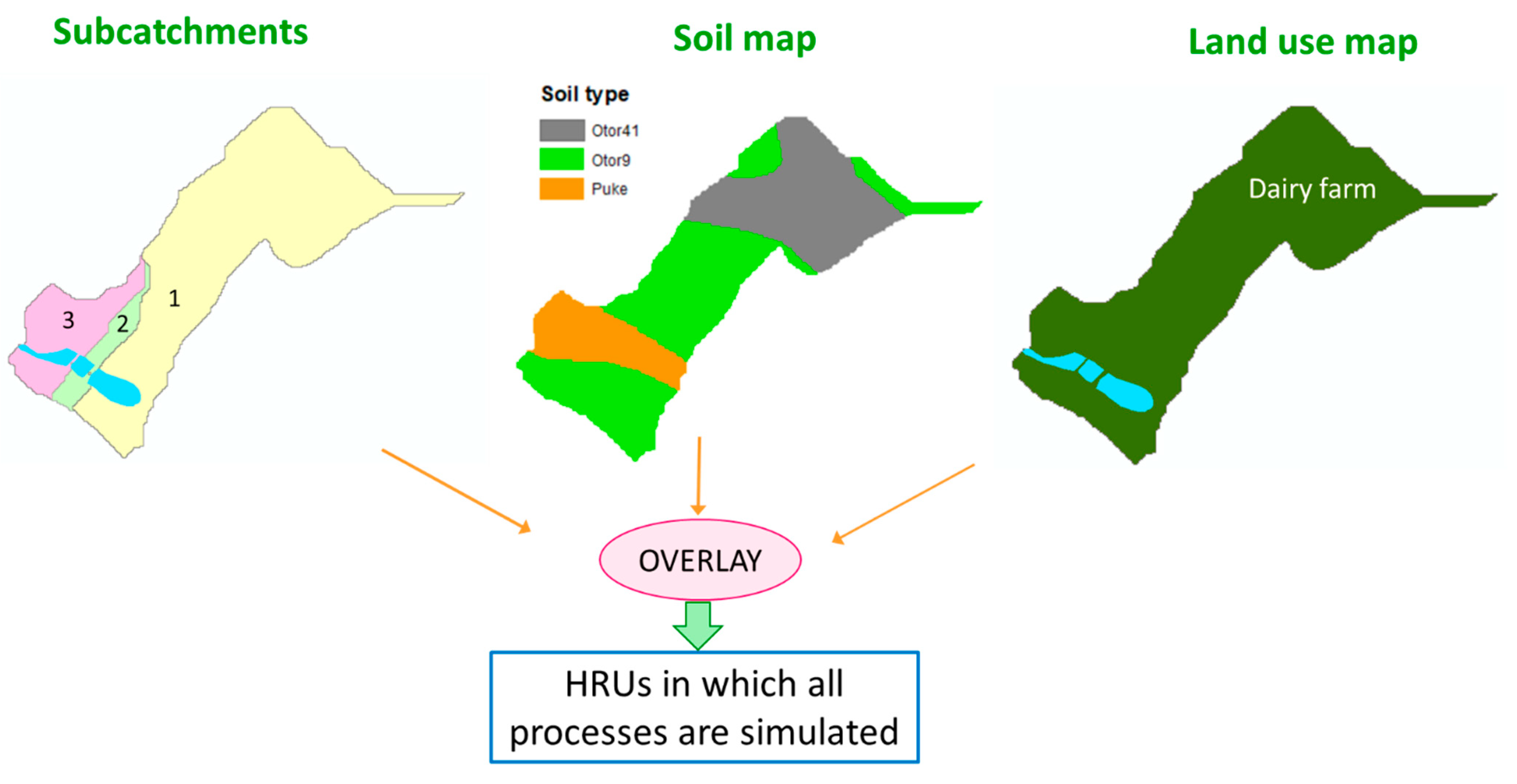
Soil type and soil characteristics were taken from S-map [41] down to the soil sibling level. There were three main soil types (mostly loamy soil) distributed in this catchment (Figure 3). The land-use map includes a wetland (4.2% of the catchment) surrounded by dairy pastures (95.8%). As the catchment is mostly flat, slope was assumed not to be a part of HRU division. Accordingly, nine HRUs were created, each of which is a unique combination of soil and land-use types. An illustration of the HRU division is shown in Figure 3. The daily climate data required by SWAT, including rainfall, maximum and minimum temperature, relative humidity, solar radiation, and windspeed were captured from an onsite climate station.

2.4.3. Estimates of Nitrogen Inputs

Nitrogen input sources to the Owl Farm wetland catchment include manure from dairy-cow grazing, fertilizer application, and atmospheric deposition (Table 3). Manure from dairy cow grazing was estimated based on the number of dairy cows in the drainage area and the characteristics of dairy-cow manure. There were 410 cows in the total 144 ha grazed pasture area of Owl Farm, which means a stocking rate of 2.85 cattle/ha. This stocking rate was applied to estimate the amount of manure in the wetland catchment area. Manure from dairy cow grazing was the highest nitrogen source with 266 kg N/ha/year. Fertilizer application was the second highest source. The application of fertilizers to support pasture growth was 133 kg N/ha/year, while dairy shed effluent applied to pasture contributed 46 kg N/ha/year. Moreover, a small amount of nitrogen came from atmospheric deposition. Parfitt et al. [42] reported wet deposition in New Zealand at around 1.5 kg N/ha, and dry deposition 5–10 kg N/ha; thus, 7.5 kg N/ha was inputted into the SWAT model as dry deposition with the assumption that 50% is ammonium-N and 50% is nitrate-N.

2.5. The Wetland Model

2.5.1. Water Balance in a Wetland Cell

The basic concept of the hydrological model for the wetland is based on water balance. For each wetland cell, the input comprises direct rainfall on the cell surface area, inflow from its sub-catchment, and inflow from the upstream wetland cell. In the case of the Owl Farm wetland with the existence of a tile-drain draining into cell 1, the catchment flow includes: surface runoff, lateral flow, groundwater flow (partitioned according to source area across the three cells), and tile flow (for only cell 1) (Figure 4). The loss from wetland includes evapotranspiration, as well as infiltration into the bottom of the wetland. The outflow of the cell is the water volume exceeding the cell storage (Equation (1)).
V t = V s t o r e d + Q i n Q o u t + Q p Q i Q E T
where V t is the water storage at the end of the time step (m3), V s t o r e d is the water storage at the beginning of the time step (m3), Q i n is the inflow of the wetland cell (m3), Q o u t is the outflow of the wetland cell (m3), Q p is the direct rainfall on the wetland cell (m3), Q i is the infiltration into the bottom of the wetland cell (m3), and Q E T is the evapotranspiration from wetland cell area (m3).
Direct rainfall
Q p = i A
where i is the rainfall rate (mm/day) and A is the area of the wetland cell (m2).
Infiltration
Q i = K A
where K is the hydraulic conductivity of the soil (mm/day) and A is the area of the wetland cell (m2).
Evapotranspiration
Q E T = P E T A E T c o e f f
PET: potential evapotranspiration, estimated by the Pennman–Montieth method (mm/day); ETcoeff is the evaporation coefficient; and A is the area of the wetland cell (m2).
Inflow
Q i n = Q S R + Q T i l e + Q G W
where QSR is the surface runoff from the sub-catchment draining to the wetland cell (m3/day), QTile is the tile flow from the sub-catchment (m3/day), and QGW is the groundwater flow from the sub-catchment (m3/day).
Outflow
Q o u t = 0   if   S t     maxvol                                         Q o u t = S t m a x v o l   if   S t   >   maxvol
where St is volume of the water stored in the wetland cell at the end of the time step (m3/day) and maxvol is the maximum volume of the wetland tank (m3/day).
As the Owl Farm wetland contains 3 main cells, we used a three-tanks-in-series approach to model the wetland in which the water moves in order from cell 1 to cell 3. Each cell also receives flow from its own subcatchment. The inflow from the catchment is simulated by SWAT in different flow types which are then fed into the wetland model. The wetland model then simulates the wetland hydrological processes and the movement of water through the wetland cells and estimates the outflow of each wetland cell.

2.5.2. Nutrient Mass Balance in a Wetland Cell

Nutrient mass balance in a wetland cell is presented in the following equation:
M t = M 0 + ( M c a t c h m e n t + M a t m + M u p c e l l ) ( M i + M o u t ) M r e m o v e d
where M t is the amount of nutrient (kg) at the end of the time step, M 0 is the amount of nutrient at the beginning of the time step (kg), M c a t c h m e n t is the nutrient loss from the catchment area to the wetland cell (kg), M a t m is the nutrient input to the wetland surface area from atmospheric deposition (kg), M u p c e l l is the amount of nutrient from the direct upstream wetland cell, M i is the amount of nutrient loss to the bottom of the wetland cell by infiltration (kg), M o u t is the amount of nutrient transported out of the wetland cell (kg), M r e m o v e d is the amount of nutrient removed within the wetland cell (kg). The microbial denitrification of nitrate-N contained in water slowly infiltrating through the saturated organic sediments in the base of the wetland is likely to be substantial based on the research of Brauer et al. [44], Gordon et al. [45], and Larson et al. [46].
Nutrient input
The nutrient input to a wetland cell includes nutrient loads from catchment drainage ( M c a t c h m e n t ), from atmospheric deposition ( M a t m ) , and from the upstream wetland cell ( M u p c e l l ). The nutrient output of a wetland cell includes nutrient loss through infiltration and to the downstream wetland cell. M c a t c h m e n t for each cell was predicted by SWAT as the summation of nutrient loading transported by surface runoff, tile flow, and groundwater flow. Annual wet and dry atmospheric N deposition as reported by Parfitt et al. [42], was disaggregated into the daily M a t m based on the measured daily rainfall. M u p c e l l was the output from the upstream cell, if any.
Nutrient removal
Nutrients are removed within the wetland cell by different processes (plant uptake, denitrification, settling), but these removal processes are simulated together using a first-order decay function (Equation (9)).
The nutrient concentration at the beginning of the time step ( C i n i , t ) is calculated as:
C i n i , t = M 0 + M c a t c h m e n t + M a t m + M u p c e l l V s t o r e d + Q p + Q i n
where C i n i , t is the amount of nutrient (kg) at the beginning of the time step, M 0 is the amount of nutrient stored in the wetland cell at the beginning of the time step (kg), M c a t c h m e n t is the nutrient loss from the catchment area to the wetland cell (kg), M a t m is the nutrient input to the wetland surface area from atmospheric deposition (kg), M u p c e l l is the amount of nutrient from the direct upstream wetland cell, V s t o r e d is the water storage at the beginning of the time step (m3), Q p is the direct rainfall on the wetland cell (m3), and Q i n is the inflow of the wetland cell (m3).
The amount of nutrient removal ( M r e m o v e d ) is calculated as:
M r e m o v e d = k t C i n i , t A
where k t is the removal rate in the wetland cell (m/day) and A is the surface area of the wetland cell.
In order to take into account the temperature dependence of the nutrient-removal rate, we used the Arrhenius equation:
k t = k 20 Ɵ ( T 20 )
where k 20 is the nutrient removal rate at a water temperature of 20 °C, Ɵ is the temperature coefficient, and T is the water temperature (°C).
In this study, we assumed that all the cells in Owl Farm wetland have the same removal rate ( k 20 ).
The nutrient concentration after removal ( C e n d , t ) is calculated by Equation (11). This concentration is used to calculate the nutrient out-load of the wetland cell and nutrient loss to infiltration.
C e n d , t = M 0 + M c a t c h m e n t + M a t m + M u p c e l l M r e m o v e d V s t o r e d + Q p + Q i n
Nutrient loss by infiltration ( M i )
M i = C e n d , t Q i
where C e n d , t is the nutrient concentration after removal and Q i is the amount of water infiltrated to the bottom of the wetland cell.
Nutrient loss through outflow ( M o u t )
M o u t = C e n d , t Q o u t
where C e n d , t is the nutrient concentration after removal and Q o u t is the amount of water leaving the wetland cell.
The nutrient out-load of the wetland cell contributes as nutrient input to the direct downstream wetland cell.

2.6. Model Calibration

Model calibration was carried out in two stages: (i) flow calibration and (ii) nitrogen calibration.

2.6.1. Flow Calibration

Ten flow-related parameters in SWAT and one parameter (ETcoeff) in the wetland model were used as calibrated parameters (Table 4). We used Monte Carlo sampling to randomly generate values for a high number of parameter sets. Each parameter set was run with the modelling framework which includes running the SWAT model, using the flow results to feed into the wetland model, and then running the wetland model to provide the simulated outflow of the wetland. Subsequently, the simulated and measured wetland outflow (outlet of wetland cell 2) were compared and the goodness of fit (Nash–Sutcliffe efficiency, NSE [47] was calculated. We repeated this procedure for all generated parameter sets and the optimal parameter set with the best goodness of fit was selected.

2.6.2. Nitrogen Calibration

The flow-calibrated model setup was used to calibrate nitrogen load. In this case study, we focused on calibrating the nitrate load, as the number of nitrate measurements (available in grab sampling, event sampling, and continuous measurement) were significantly higher than for other nitrogen species and TN (available in grab and event samples with a few missing data). The same calibration methodology was applied with seven N-related parameters in the SWAT model and two N-related parameters in the wetland model (Table 4). The nitrate-load model prediction was calibrated against the measured nitrate load at the wetland outlet, and NSE continued to be used as a criterion to select the optimal parameter set.

2.7. Evaluate Wetland Performance on Nitrogen Removal

We evaluated the wetland performance on nitrogen removal by two approaches: (i): based on spot-measured water-quality concentrations and SWAT-simulated flow; and (ii): fully based on calibrated SWAT–wetland modelling results. In approach I, nitrogen removal was calculated only on sampling days, while approach II provided daily nitrogen removal based on daily modelling results.
(i)
Approach I: based on spot-measured water-quality concentrations and SWAT-simulated flow
On each sampling day, based on the measured concentrations from different types of flow, and our SWAT model prediction of flow components on that day, we calculated the nitrogen (nitrate-N, TN) load input to the wetland, nitrogen load leaving the wetland, and the percentage of nitrogen load removal.
% N l o a d r e m o v a l = N l o a d i n N l o a d o u t N l o a d i n × 100
where Nloadin is the nitrogen input load to the wetland, and Nloadout is the nitrogen load coming out of the wetland.
As there was no measured nitrogen concentration for surface runoff and it is a relatively small component of inflow, we assume that the surface runoff concentration is the same as the tile flow.
N l o a d i n = N c o n c t i l e S R + t i l e f l o w + N c o n c G W G W
where Nconctile is the nitrogen concentration measured at the drained tile, NconcGW is the nitrogen concentration measured at the groundwater well; SR, tileflow, and GW are the surface runoff, tile drainage, and groundwater flow simulated by SWAT.
N l o a d o u t = N c o n c o u t l e t o u t f l o w
where Nconcoutlet is the nitrogen concentration measured at the wetland outlet and outflow is the simulated wetland outflow.
(ii)
Approach II: based fully on calibrated SWAT and wetland model results
In this approach, we used the linked SWAT–wetland model to simulate all the processes in the catchment and subsequent reduction in the wetland. The nitrogen input, output, and removal associated with the wetland were all simulated by the model.

3. Results and Discussion

3.1. Model Calibration

3.1.1. Hydrological Simulation

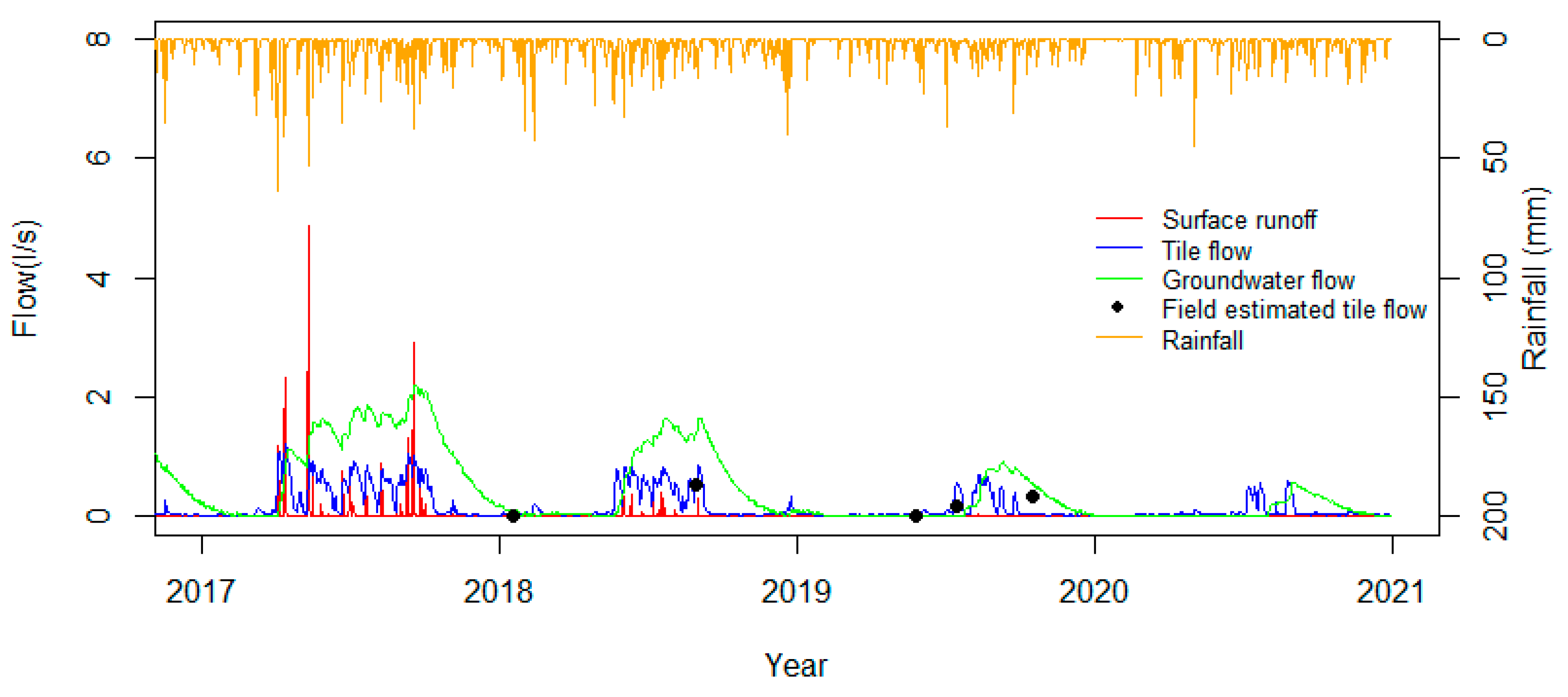
A comparison of the wetland outflow predictions with the continuous flow measurement in Figure 5 shows that the linked catchment–wetland model can simulate the occurrence, magnitude, and variation in the wetland outflow reasonably well. NSE, the goodness of fit measuring the discrepancy between the observed and predicted flow, is at 0.7 (an NSE equal to 1 means a ‘perfect’ model). Based on the model evaluation guidelines of Moriasi et al. [48], the model performance can be rated as ‘good’. A comparison of the flow predictions with the limited manual flow estimations during regular sampling (simulated flow versus field estimate outflow in Figure 5 also showed that the SWAT flow predictions were realistic in both magnitude and temporal variation. This suggests that the model provides a reasonable representation of the hydrological processes in the upland catchment and the constructed wetland, illustrating the utility of the modelling approach when there are missing data or challenges in field measurements.

3.1.2. Nitrogen Simulation

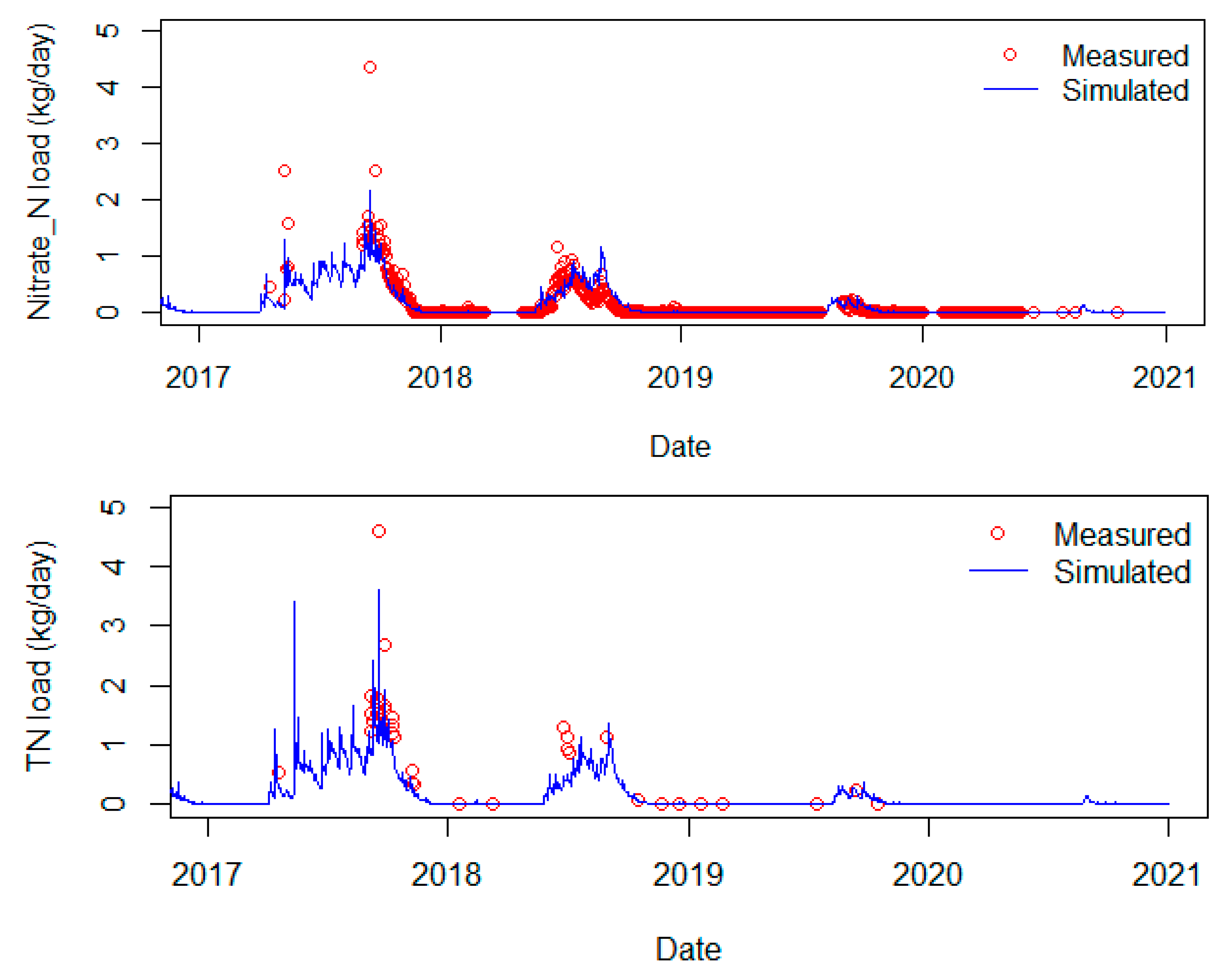
Figure 6 shows the comparison between simulated nitrate-N and TN load versus their measured loads at the wetland outlet. The goodness of fit between model predictions and measurements for nitrate load is 0.76, which is rated as ‘very good’ for daily prediction according to the model evaluation guidelines [48]. Visually, Figure 6 shows that the linked catchment–lake model was able to capture reasonable magnitudes and variations of both nitrate-N and TN loads, although it underestimated some of the high-flow events. Nitrate is the dominant nitrogen species in this catchment, shown by the median percentage of nitrate to TN derived from the model prediction (88%) and measured data (92%).

3.2. Flow and Nitrogen Load from Catchment to Owl Farm Wetland

3.2.1. Flow

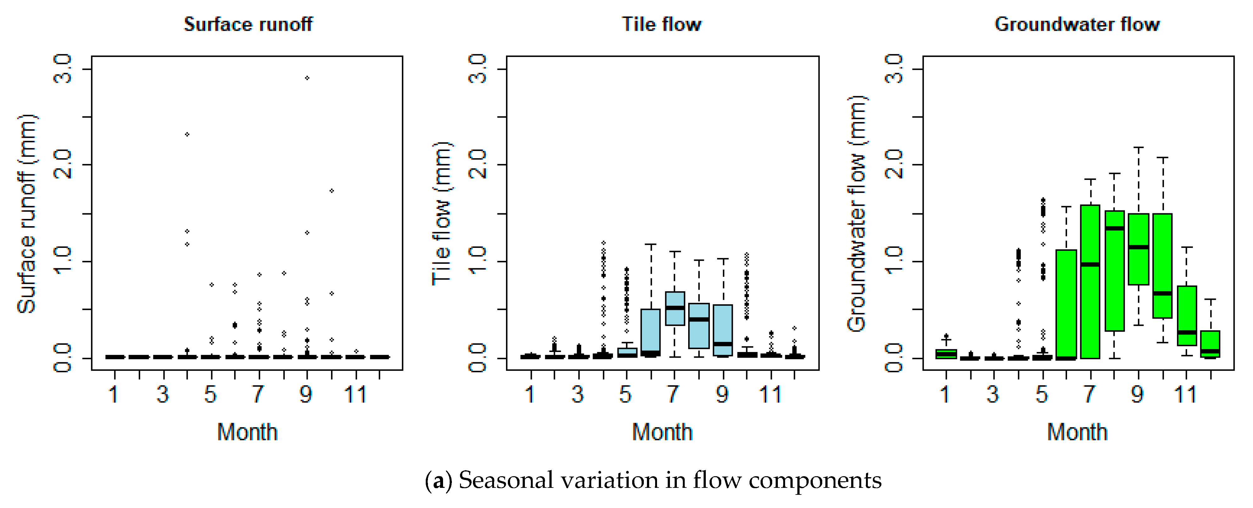
Based on the calibrated model, the water balance for each simulation year and the annual average water balance for the simulation period 2017–2020 were extracted (Table 5). The annual average rainfall for the period monitored was 997 mm, 663 mm was lost through evapotranspiration, and approximately 334 mm entered the wetland. A small amount of 9 mm contributed as surface runoff, which accounts for only 2.7% of the total flow. Subsurface tile drainage contributed 83 mm, accounting for 24.9% of the total flow. Groundwater was the dominant contributor in this catchment with 242 mm, which equals 72.4% of the total flow. Among the three simulated years, 2017–2018 was the wettest year with rainfall at 1295 mm, 2018–2019 was an intermediate year, while 2019–2020 was a dry year with only 718 mm rainfall (a serious drought involving one of the lowest annual rainfalls ever recorded in the vicinity [49]). The climatic differences in these three years resulted in significant differences in the flow components and quantities contributing to the wetland (Table 5).
Figure 7 illustrates temporal variation in the flow components contributing to the wetland from 2017 to 2020. It can be clearly seen from Figure 7 that the response of flow generation to rainfall changes by season. Tile drainage and surface runoff mostly contribute flow to the wetland in winter and spring (June to September) with very limited contributions in other seasons. Surface runoff usually stays very low unless high-intensity rainfall events occur, while tile flow has a continuous contribution during active seasons. Although rainfall occurs in summer, it rarely generates tile drainage and surface runoff. This is because evapotranspiration is high, the groundwater level is too low to generate tile drainage, and the soil is too dry to generate surface runoff. Groundwater contributes to the wetland during most months but has a very small contribution in summer, resulting in the drying out of the wetland during this period. Groundwater contributions are higher during winter–spring, which corresponds to a higher rainfall and colder temperatures with reduced evapotranspiration.

3.2.2. Nitrogen Load

The SWAT predictions of nitrogen load to the wetland driven by different flow components are shown in Table 6. Nitrate is the dominant nitrogen species in the total amount of nitrogen transported to the wetland, which is compatible with the measured data. For the period of 2017–2020, SWAT estimates that the wetland received 3.3 kg N/ha/year in organic form and 27.3 kg N/ha/year in nitrate form. Nitrate from the catchment was driven to the wetland by surface runoff, tile drainage, and groundwater flow. Among these flow types, groundwater was the dominant pathway for nitrate, contributing 22.4 kg N/ha/year and accounting for 82.1%. Tile drainage provided an average of 4.8 kg N/ha/year, accounting for 17.6%, while a very small amount was contributed by surface runoff.

3.2.3. Seasonal Variation in Flow and Nitrate Yield

Due to the mobility of nitrate, the seasonal variation in nitrate yield follows the distribution of flow (Figure 8). Surface runoff usually stays low and is higher in winter from June to August, which results in an increase in nitrate yield driven from surface runoff in winter. In terms of tile drainage, June to September is the period that tile drainage is generated, with the highest occurring in July and August. In the remaining months, tile drainage only occurs when there is a high-rainfall event. Therefore, the nitrate yield from tile flow also enters the streams mostly from June to September. Nitrate yield from groundwater has the same pattern as groundwater flow, which is lower from summer–autumn and higher from winter–spring.

3.3. Residence Time

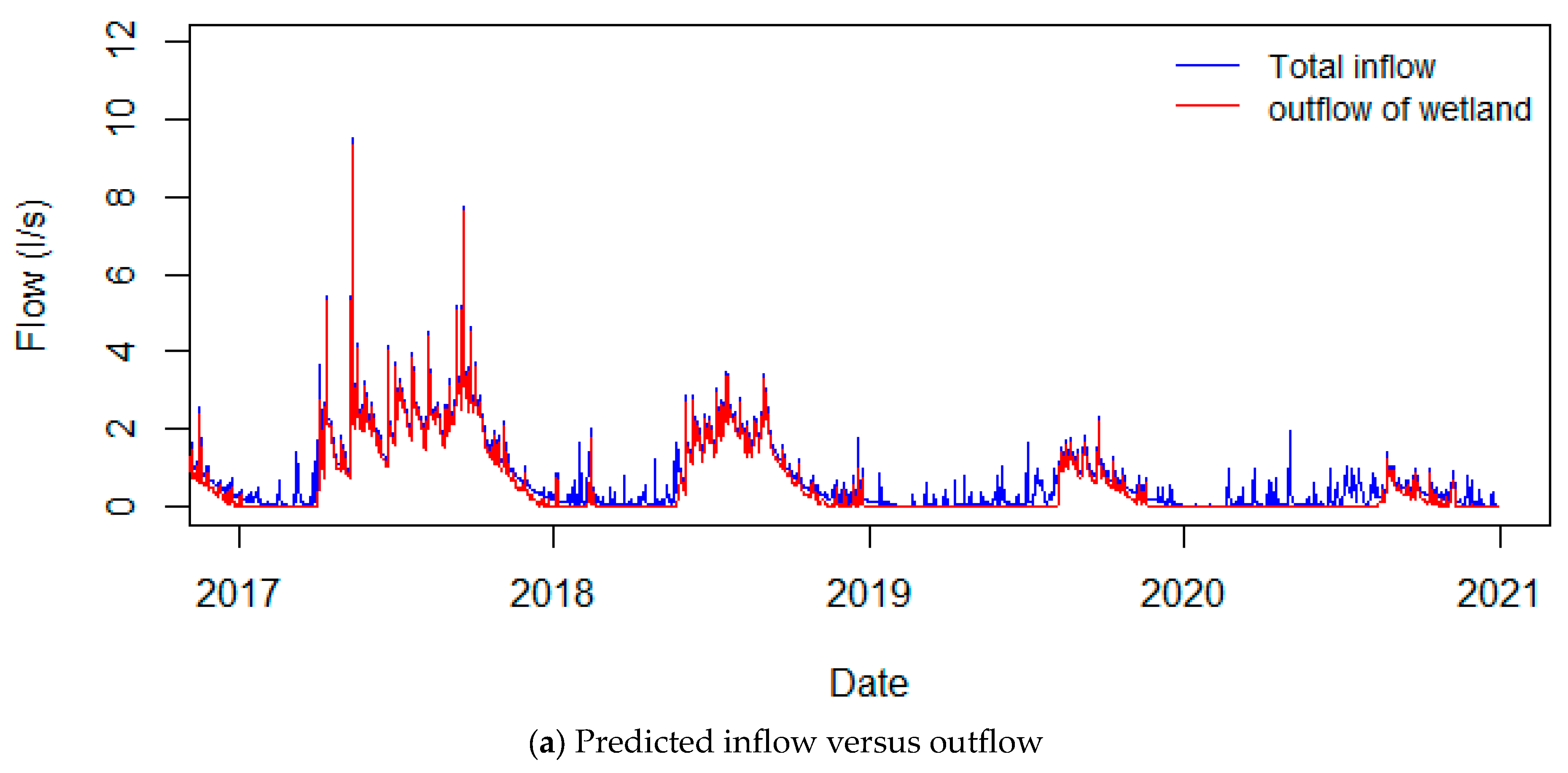
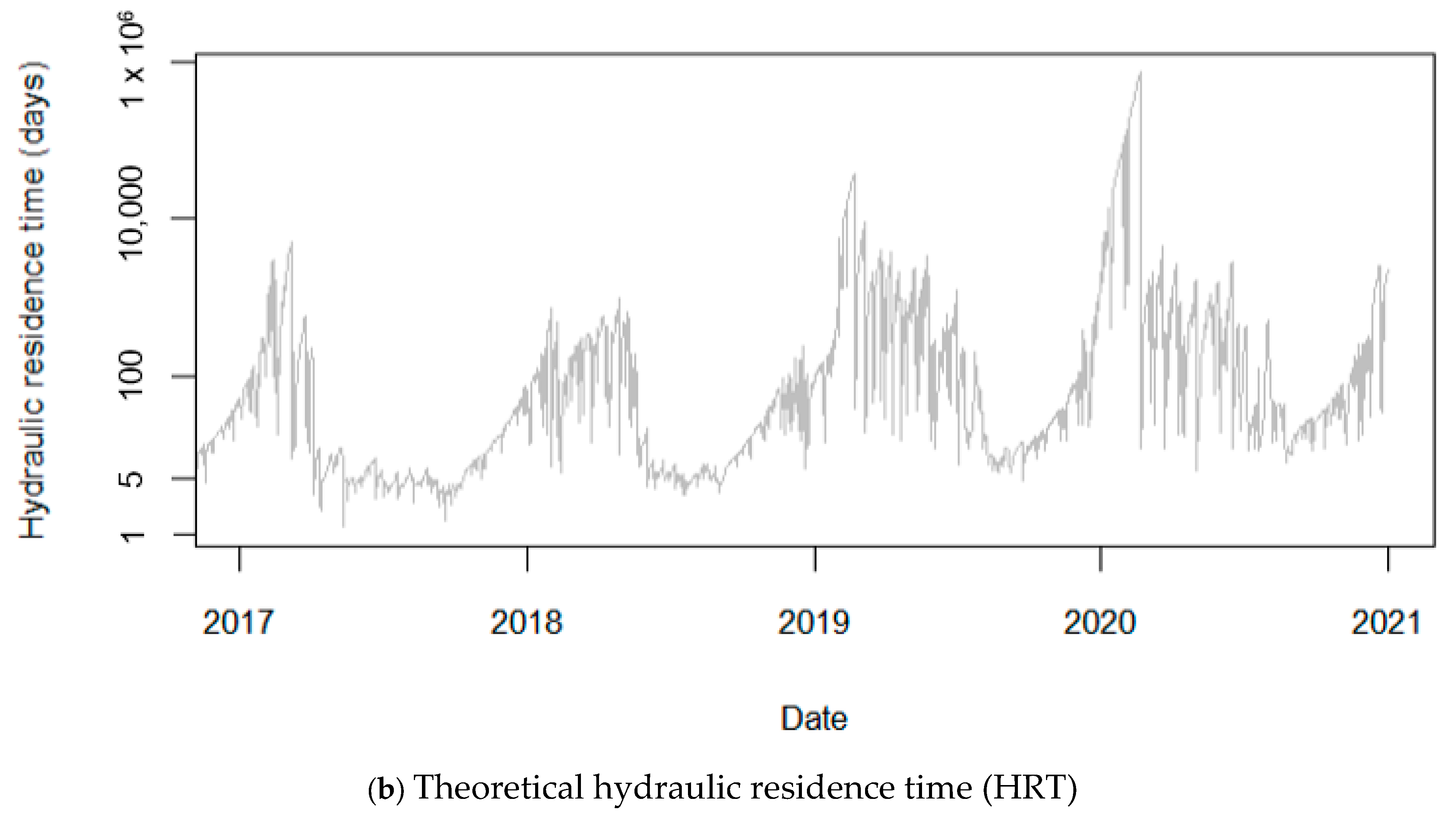
Figure 9a presents the temporal variation in the predicted inflow versus predicted outflow of the wetland, while Figure 9b shows the time series of theoretical hydraulic residence time (HRT) calculated by dividing the wetland inflow by the wetland volume. It can be clearly seen in Figure 9a that in the low-flow period (December–May), the wetland can retain all the water coming in; therefore, the wetland outflow is very small or nil. This is supported by the fact that the wetland becomes dry and there is no outflow in summer. In the high-flow period (June–November), the wetland has a much lower retention capacity. At the highest flows, recorded during the period 2017–20120, the theoretical HRT dropped to 1.23 day, but it is characteristically around 5.7 d during the winter/high-flow period.

3.4. Nitrogen Concentration versus Flow

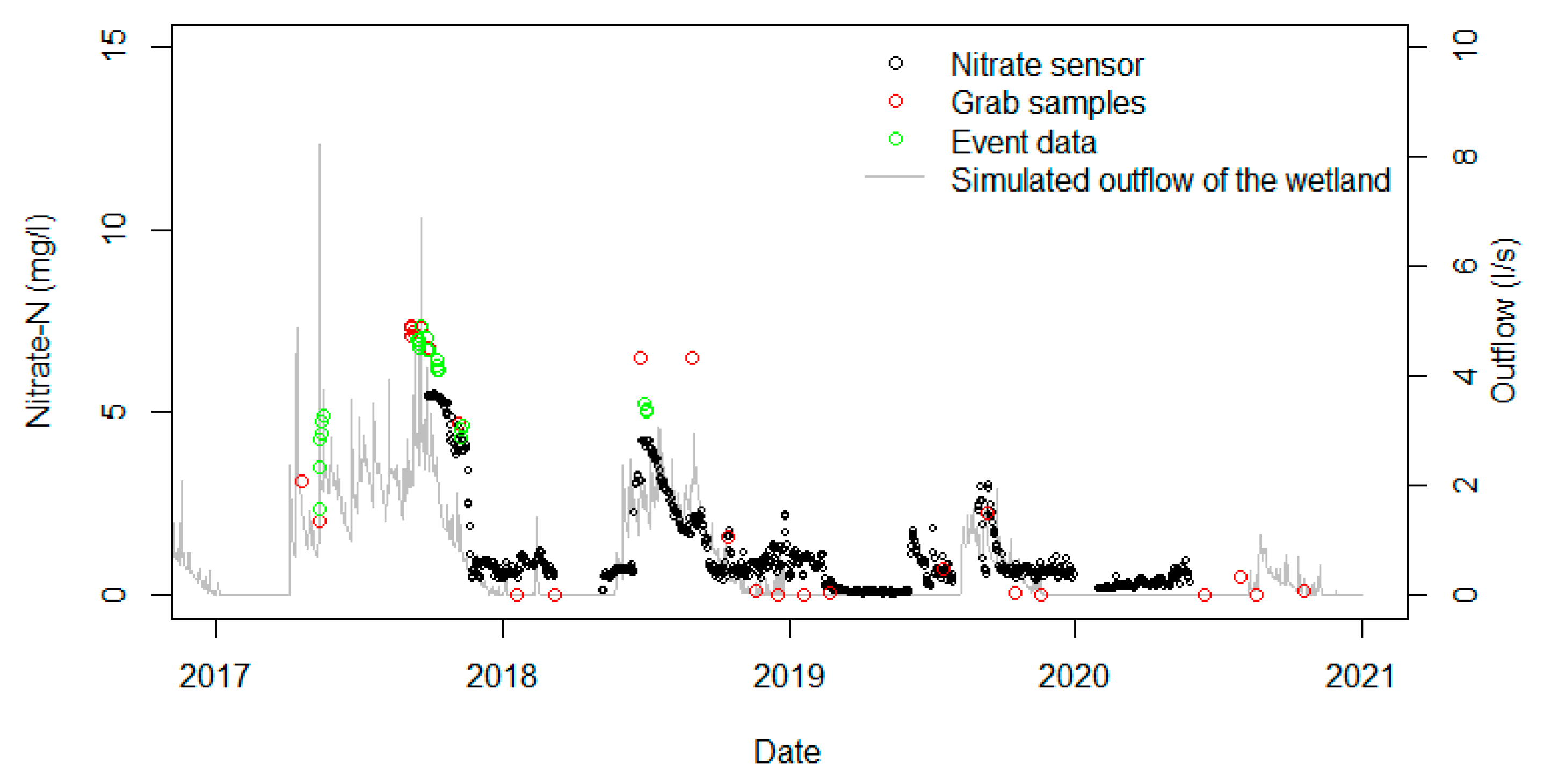
Figure 10 shows the comparison of nitrate-N concentrations in different types of samplings and a comparison of the dynamics of nitrate-N concentration with the wetland outflow dynamics. It can be noted that the nitrate-N concentrations from different types of sampling are quite compatible with each other. On days when the measured nitrate-N concentration is available from two or three samplings, the measured data are of the same magnitude as one another, although they are not exactly the same values.
The seasonal dynamics of nitrate-N concentration are fairly similar to the dynamics of flow at the outlet of the wetland (Figure 10). In the high-flow period (winter to spring in New Zealand), nitrate-N concentration is also high, as high flow transports nitrate-N to the wetland. Moreover, in the high-flow period that generally corresponds to winter/spring in New Zealand with a low temperature, plant growth and nutrient uptake are low; thus, high nitrate-N is available in the soil for transport with flow. On the other hand, nitrate-N concentration in the wetland outflow is low in the low-flow period. This period is usually from summer to early autumn with a high temperature, activating plant growth and nutrient uptake, and leaving less nitrate-N in the soil to be transported by flow.
The periods of high flow and low flow can change between years depending on the frequency, intensity, and duration of precipitation (Figure 10). There was a general trend of reducing annual rainfall at Owl Farm over the monitoring period. In the first and wettest year, 2017–2018, rainfall was slightly above the long-term average. In subsequent years, rainfall was below normal levels, with record summer droughts [49]. Accordingly, the high-flow period extended from April to November (late autumn to late spring) in 2017, while in subsequent years, there is a much shorter flow period with a negligible flow from the wetland until August (late winter).
The nitrogen concentrations of grab sampling and event sampling at three measured sites (upstream well, upstream tile, and downstream outlet) are compared with one another and with the simulated outflow in Figure 11. During the whole monitored period, the nitrate-N concentrations at the downstream outlet (blue dots) are always smaller than at the upstream well (red dots) and at the upstream tile (green dots). Nitrate-N concentration at the upstream tile was the highest with a median value of 11.3 mg/L, followed by nitrate-N concentration at the upstream well with a median value of 6.3 mg/L, while the median concentration at the downstream outlet decreased to 4.7 mg/L (Figure 12a). This indicates that nitrate-N removal was occurring in the wetland. The upstream tile had a significantly higher nitrate-N concentration than the upstream well, as well as a larger value range. This reflects the more rapid transport of tile drainage transported to the wetland with limited contact with the soil and associated biogeochemical processes. In comparison, the concentration in the upstream well was much lower and more varied, likely due to partial denitrification as interflow and shallow groundwater travel through the soil profile.
The TN concentrations generally showed similar behaviour to that of nitrate-N. There were two exceptions, occurring on 21 February 2019 and 19 November 2019, where the measured TN concentration at the downstream outlet was higher than at the upstream well (blue-highlighted events in Figure 11b). On both days, ammonia and E. coli were abnormally high at the downstream outlet compared to the catchment inlets. This may indicate localised inputs of organic N, e.g., excreta from waterfowl or other wildlife close to the outlet.

3.5. Performance of the Owl Farm Wetland on Nitrate-N Removal

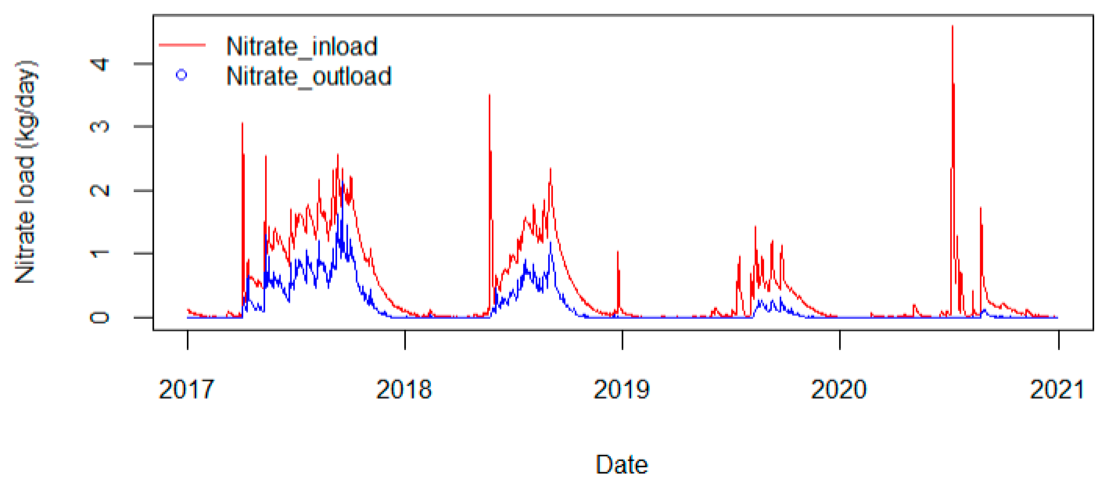
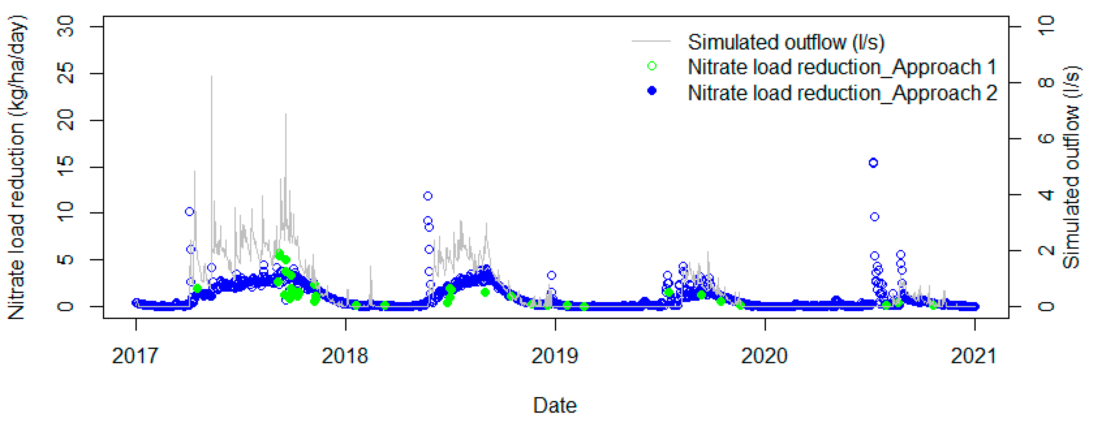
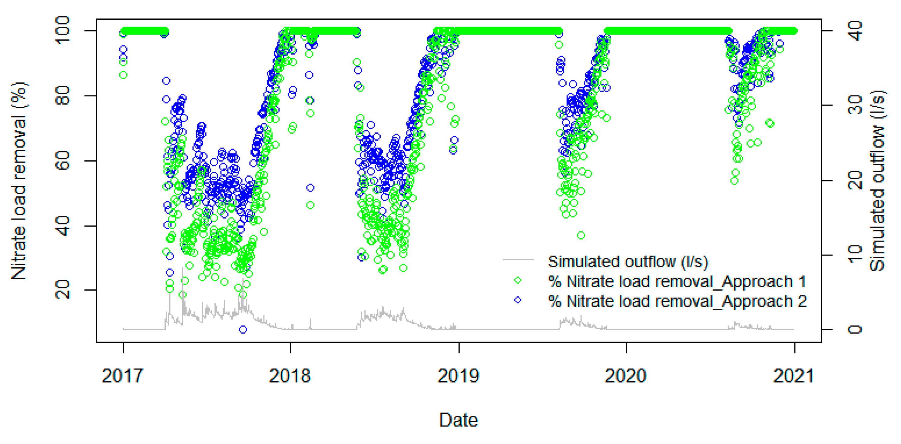
In this section, we focus on the nitrate-removal efficiency of the wetland, as nitrate is the dominant form entering the wetland and the deployment of a high-frequency nitrate sensor provides a much richer dataset. Figure 13 presents the model predictions of the nitrate load entering and leaving the wetland. Figure 14 shows the nitrate-load reduction (in kg/ha/day) estimated by approach I: based on the measured concentration and simulated flow on sampled days, and approach II: based fully on the dynamic model predictions. Subsequently, the percentage of nitrate-load removal was calculated using the two approaches and compared against the wetland outflow and theoretical hydraulic residence time (Figure 15).
Figure 14 shows that the estimates of nitrate-load reduction using approach I are comparable with the results of approach II on sampled days. However, approach II provides a full time series of nitrate-load reduction, while approach I is only limited to days for which measurements are available. Generally, both approaches clearly show a high nitrate-load reduction in high-flow periods (winter–early spring) because these periods account for most of the nitrate load transported from the catchment to the wetland (see nitrate in-load in Figure 13). During the transition from low-flow to high-flow periods (i.e., at the beginning of the high-flow period in 2018–2019 and 2020–2021), approach II shows a very high nitrate-load reduction (around 12 kg/ha/day). This is because on these transition days, the nitrate in-load is high due to the accumulation of nitrate in the catchment during the previous low-flow period, whereas the wetland is still quite dry and can retain and remove all or most of the catchment nitrogen inputs without any discharge (Figure 13).
Looking at the efficiency of the nitrate-N load removal, both approaches show a percentage removal decreased exponentially as the wetland outflow rate increases, with an R2 of 0.86 and 0.96, respectively (Figure 15). Similarly, nitrate removal increased exponentially with HRT, with an R2 of 0.83 and 0.89, respectively. These relationships indicate that on days when the outflow is very small and retention times in the wetland were extended, N removal could be very high at approximately 90%. The removal efficiency dropped relatively quickly when the flow increased. During high-flow events, the wetland percentage removal of nitrate-N decreased to around 20–40%, but the overall load removal was still higher than in low-flow periods.
Figure 16 shows the instantaneous nitrate removal of the wetland for the period 2017–2020 using the two approaches. For approach I, we applied an exponential function representing the relationship between nitrogen removal and simulated outflow (Figure 15). For approach II, nitrate removal was extracted from the modelled results. The variation in estimated nitrogen removal versus wetland outflow dynamics shows that nitrate removal is very dynamic and highly dependent on flow and seasons. In the low-flow period (usually summer to autumn), nitrogen removal is high as the wetland can retain most of the water and denitrification has more time to occur. In the high-flow period, the nitrogen-removal efficiency is generally much lower because of shorter retention times; however, the wetland still has the capacity to remove nitrogen during storm events. Despite the reduced efficiency in high-flow periods, the quantity of nitrogen removed increases during these periods due to high nitrogen loading from the catchment, which is clearly shown in Figure 14.
Using the linked catchment–wetland model as approach II, the nitrate entering and leaving the wetland and the nitrate-removal rate were calculated for each monitoring year as shown in Table 7. Overall, for the 3-year simulation period, the Owl Farm wetland was able to remove 61% of the nitrate-N load coming in the wetland. The nitrate-removal efficiency changes every year depending to a major extent on the climate drivers of the influent regime. In the wettest year 2017–2018, a large load of nitrate-N was exported to the wetland (310 kg N/year). The wetland-removal efficiency was the lowest at around 55% during this year, but the overall load of nitrate-N removed was the highest at 170 kg N/year. On the other hand, in the driest year 2019–2020, when smaller loads of nitrate entered the wetland, the wetland was able to retain and remove above 80% of the nitrate, but at much lower overall mass reduction rates (54 kg N/year).
Figure 17 presents the average annual nitrate mass balance in each wetland cell and the connection between cells simulated by the wetland model. Cell 1 received the highest amount of nitrate, 153.6 kg N/year, accounting for more than 80% of the nitrate-N entering the wetland. This cell had the largest subcatchment area, and there was a subsurface tile drain acting as a fast pathway for nitrate transport. Cell 1 also had the highest amount of nitrate removed with 80.9 kg N/year, accounting for 71% of the total amount of nitrate removal because of its large area resulting in a high retention capacity. In cell 2, the dominant nitrate input was nitrate load from cell 1, while the subcatchment contribution was relatively low due to the small drainage area. Nitrate was further removed in this cell at a rate of 13.7 kg N/year, accounting for 12% of the nitrate removal. Cell 3 received nitrate mainly from cell 2 and its subcatchment. As the area of this cell was quite small, it only removed 18.7 kg N/year equalling 16.5% of the nitrate removal.

4. Conclusions

This study applied a linked catchment–wetland model to evaluate the effectiveness of Owl Farm constructed wetland in removing nitrate-N loading from a dairy-pasture catchment. The linkage of SWAT and a water and mass balance-based wetland model successfully simulated the hydrological processes of the catchment and wetland and provided flow predictions that fit reasonably with the available measurements, as well as filling in gaps of missing inflow and outflow data. The linked model also gave a reasonable estimates of nitrate load entering and leaving the wetland, which helps to evaluate the wetland’s removal performance.
The efficiency of Owl Farm wetland in nitrate removal was estimated by two approaches: (i) approach I is based on the measured water-quality concentration and simulated flow, and (ii) approach II is based fully on linked model predictions. In both approaches, we found that nitrate removal was closely exponentially related to the wetland outflow rate. Approach I estimated nitrate removal empirically based on the exponential relationship with wetland outflow. On the other hand, approach II estimated nitrate removal using process-based model predictions. Both approaches indicated that Owl Farm constructed wetland is very effective in nitrate removal. The wetland is very effective at retaining flow and removing nitrogen during low-flow periods, at more than 90%. This capacity reduces with increasing flow. However, during storm events with limited flow retention, the wetland is still able to remove nitrate with a lower rate, probably owing to denitrification. Overall, the Owl Farm wetland removed approximate 60% of the received nitrate load during the simulation period 2017–2020.
The relatively high nitrogen-removal efficiency estimated for this wetland is likely related to the predominance of baseflow inputs from groundwater seepage rather than flashy surface and drain-flows common in many agricultural landscapes [13]. This would have buffered the inflows, spreading them out over a longer period and extending their residence time within the wetland. In the latter years, drought conditions at the site also reduced the flows into the wetland so as to increase the residence times within the wetland. A corollary of this was the relatively low levels of mass removal of nitrogen for these years.
Although both approaches are able to evaluate the wetland performance, approach II provides increased understanding of the catchment and wetland responses to the movement of water and nitrate within the catchment, from the catchment to the wetland, and between the wetland cells. The process-based approach is able to estimate the nitrate load entering and leaving the wetland, and calculate the amount removed via the difference between these loads, at any time step in any wetland cell. Moreover, the process-based SWAT modelling approach provides the opportunity for predictions under future climate change scenarios for different catchment land-uses and different wetland extents.

Author Contributions

Conceptualization, L.H. and C.C.T.; methodology, L.H., J.P.S.S., V.M. and C.C.T.; software, L.H.; validation, L.H., formal analysis, L.H., investigation, L.H., J.P.S.S. and V.M.; resources: C.C.T.; data curation: J.P.S.S. and V.M.; writing—original draft preparation, L.H.; writing—review and editing: C.C.T.; visualization, L.H.; supervision, C.C.T.; project administration, C.C.T.; funding acquisition, C.C.T. All authors have read and agreed to the published version of the manuscript.

Funding

The wetland was constructed in 2016 with co-funding from the Waikato River Authority and Waikato Regional Council, with support from Opus Consultants and Lincoln Agritech. This study was supported through NIWA’s Strategic Science Investment Fund and the Doubling On-Farm Diffuse Pollution Mitigation Project (C01X1818) funded by the New Zealand Ministry of Business, Innovation and Employment.

Data Availability Statement

Data sharing is not applicable to this article.

Acknowledgments

We thank Owl Farm, a joint venture between St Peter’s School, Cambridge, and Lincoln University, for providing access to the wetland and information on farm management. We thank Roland Stenger of Lincoln Agritech for initially involving us in the project and providing preliminary groundwater and tile-drain monitoring data for the site. Stephan Heubeck at NIWA ably assisted with stormflow and high-frequency nitrate-sensor sampling. All water-quality analyses were undertaken by Hill’s Laboratories, Hamilton, which is accredited by International Accreditation New Zealand (IANZ) ISO/IEC 17025:2017. We are grateful to Carl Sheridan of Architects of Change for producing the graphical abstract.

Conflicts of Interest

The authors declare no conflict of interest.

References

  1. Mateo-Sagasta, J.; Zadeh, S.M.; Hugh, T. Water Pollution from Agriculture: A Global Review; Food and Agriculture Organization of the United Nations: Rome, Italy; International Water Management Institute: Colombo, Sri Lanka, 2017. [Google Scholar]
  2. Howarth, R.W. Coastal nitrogen pollution: A review of sources and trends globally and regionally. Harmful Algae 2008, 8, 14–20. [Google Scholar] [CrossRef]
  3. King, K.W.; Williams, M.R.; Macrae, M.L.; Fausey, N.R.; Frankenberger, J.; Smith, D.R.; Kleinman, P.J.A.; Brown, L.C. Phosphorus Transport in Agricultural Subsurface Drainage: A Review. J. Environ. Qual. 2015, 44, 467–485. [Google Scholar] [CrossRef] [PubMed]
  4. Smith, V.H. Eutrophication of freshwater and coastal marine ecosystems a global problem. Environ. Sci. Pollut. Res. 2003, 10, 126–139. [Google Scholar] [CrossRef] [PubMed]
  5. Withers, P.J.A.; Neal, C.; Jarvie, H.P.; Doody, D.G. Agriculture and Eutrophication: Where Do We Go from Here? Sustainability 2014, 6, 5853–5875. [Google Scholar] [CrossRef]
  6. Seidenfaden, I.K.; Sonnenborg, T.O.; Børgesen, C.D.; Trolle, D.; Olesen, J.E.; Refsgaard, J.C. Impacts of land use, climate change and hydrological model structure on nitrate fluxes: Magnitudes and uncertainties. Sci. Total Environ. 2022, 830, 154671. [Google Scholar] [CrossRef]
  7. Vymazal, J. Enhancing ecosystem services on the landscape with created, constructed and restored wetlands. Ecol. Eng. 2011, 37, 1–5. [Google Scholar] [CrossRef]
  8. Carstensen, M.V.; Hashemi, F.; Hoffmann, C.C.; Zak, D.; Audet, J.; Kronvang, B. Efficiency of mitigation measures targeting nutrient losses from agricultural drainage systems: A review. Ambio 2020, 49, 1820–1837. [Google Scholar] [CrossRef]
  9. Crumpton, W.G.; Stenback, G.A.; Fisher, S.W.; Stenback, J.Z.; Green, D.I.S. Water quality performance of wetlands receiving nonpoint-source nitrogen loads: Nitrate and total nitrogen removal efficiency and controlling factors. J. Environ. Qual. 2020, 49, 735–744. [Google Scholar] [CrossRef]
  10. Tanner, C.C.; Depree, C.V.; Sukias, J.P.S.; Wright-Stow, A.E.; Burger, D.F.; Goeller, B.C. Constructed Wetland Practitioners Guide: Design and Performance Estimates; DairyNZ/NIWA: Hamilton, New Zealand, 2022. [Google Scholar]
  11. Strand, J.A.; Weisner, S.E.B. Effects of wetland construction on nitrogen transport and species richness in the agricultural landscape—Experiences from Sweden. Ecol. Eng. 2013, 56, 14–25. [Google Scholar] [CrossRef]
  12. Tanner, C.C.; Sukias, J.P.S. Multiyear Nutrient Removal Performance of Three Constructed Wetlands Intercepting Tile Drain Flows from Grazed Pastures. J. Environ. Qual. 2011, 40, 620–633. [Google Scholar] [CrossRef]
  13. Tanner, C.C.; Kadlec, R.H. Influence of hydrological regime on wetland attenuation of diffuse agricultural nitrate losses. Ecol. Eng. 2013, 56, 79–88. [Google Scholar] [CrossRef]
  14. Kadlec, R.H.; Wallace, S.D. Treatment Wetlands, 2nd ed.; CRC Press: Boca Raton, FL, USA, 2009. [Google Scholar]
  15. Ranalli, A.J.; Macalady, D.L. The importance of the riparian zone and in-stream processes in nitrate attenuation in undisturbed and agricultural watersheds—A review of the scientific literature. J. Hydrol. 2010, 389, 406–415. [Google Scholar] [CrossRef]
  16. Restrepo, J.I.; Montoya, A.M.; Obeysekera, J. A Wetland Simulation Module for the MODFLOW Ground Water Model. Groundwater 1998, 36, 764–770. [Google Scholar] [CrossRef]
  17. Bradley, C. Simulation of the annual water table dynamics of a floodplain wetland, Narborough Bog, UK. J. Hydrol. 2002, 261, 150–172. [Google Scholar] [CrossRef]
  18. Lee, E.R.; Mostaghimi, S.; Wynn, T.M. A Model to Enhance Wetland Design and Optimise Nonpoint Source Pollution Control. JAWRA J. Am. Water Resour. Assoc. 2002, 38, 17–32. [Google Scholar] [CrossRef]
  19. Kazezyılmaz-Alhan, C.M.; Medina, M.A., Jr.; Richardson, C.J. A wetland hydrology and water quality model incorporating surface water/groundwater interactions. Water Resour. Res. 2007, 43. [Google Scholar] [CrossRef]
  20. Aragones, D.G.; Sanchez-Ramos, D.; Calvo, G.F. SURFWET: A biokinetic model for surface flow constructed wetlands. Sci. Total Environ. 2020, 723, 137650. [Google Scholar] [CrossRef]
  21. Arheimer, B.; Wittgren, H.B. Modelling nitrogen removal in potential wetlands at the catchment scale. Ecol. Eng. 2002, 19, 63–80. [Google Scholar] [CrossRef]
  22. Hattermann, F.F.; Krysanova, V.; Habeck, A.; Bronstert, A. Integrating wetlands and riparian zones in river basin modelling. Ecol. Model. 2006, 199, 379–392. [Google Scholar] [CrossRef]
  23. Arnold, J.G.; Srinivasan, R.; Muttiah, R.S.; Williams, J.R. Large area hydrologic modeling and assessment part 1: Model development. J. Am. Water Resour. Assoc. 1998, 34, 73–89. [Google Scholar] [CrossRef]
  24. Wu, K.; Johnston, C.A. Hydrologic comparison between a forested and a wetland/lake dominated watershed using SWAT. Hydrol. Process. 2008, 22, 1431–1442. [Google Scholar] [CrossRef]
  25. Wang, X.; Shang, S.; Qu, Z.; Liu, T.; Melesse, A.M.; Yang, W. Simulated wetland conservation-restoration effects on water quantity and quality at watershed scale. J. Environ. Manag. 2010, 91, 1511–1525. [Google Scholar] [CrossRef]
  26. Yang, W.; Wang, X.; Liu, Y.; Gabor, S.; Boychuk, L.; Badiou, P. Simulated environmental effects of wetland restoration scenarios in a typical Canadian prairie watershed. Wetl. Ecol. Manag. 2010, 18, 269–279. [Google Scholar] [CrossRef]
  27. Hoang, L.; van Griensven, A.; Mynett, A. Enhancing the SWAT model for simulating denitrification in riparian zones at the river basin scale. Environ. Model. Softw. 2017, 93, 163–179. [Google Scholar] [CrossRef]
  28. Lee, S.; Yeo, I.Y.; Lang, M.W.; McCarty, G.W.; Sadeghi, A.M.; Sharifi, A.; Jin, H.; Liu, Y. Improving the catchment scale wetland modeling using remotely sensed data. Environ. Model. Softw. 2019, 122, 104069. [Google Scholar] [CrossRef]
  29. Bauwe, A.; Eckhardt, K.-U.; Lennartz, B. Potential of constructed wetlands to reduce nitrate pollution in agricultural catchments. Ecol. Eng. 2022, 178, 106597. [Google Scholar] [CrossRef]
  30. Babbar-Sebens, M.; Barr, R.C.; Tedesco, L.P.; Anderson, M. Spatial identification and optimization of upland wetlands in agricultural watersheds. Ecol. Eng. 2013, 52, 130–142. [Google Scholar] [CrossRef]
  31. Comín, F.A.; Sorando, R.; Darwiche-Criado, N.; García, M.; Masip, A. A protocol to prioritize wetland restoration and creation for water quality improvement in agricultural watersheds. Ecol. Eng. 2014, 66, 10–18. [Google Scholar] [CrossRef]
  32. Neitsch, S.L.; Arnold, J.G.; Kiniry, J.R.; Williams, J.R. Soil and Water Assessment Tool Theoretical Documentation Version 2009; Texas Water Resources Institute: College Station, TX, USA, 2011.
  33. Ikenberry, C.D.; Crumpton, W.G.; Arnold, J.G.; Soupir, M.L.; Gassman, P.W. Evaluation of existing and modified wetland equations in the SWAT model. JAWRA J. Am. Water Resour. Assoc. 2017, 53, 1267–1280. [Google Scholar] [CrossRef]
  34. Kadlec, R.H. Constructed Marshes for Nitrate Removal. Crit. Rev. Environ. Sci. Technol. 2012, 42, 934–1005. [Google Scholar] [CrossRef]
  35. APHA. Standard Methods for the Examination of Water and Wastewater, 22nd ed.; American Public Health Association; American Water Works Association and Water Environment Federation: Washington, DC, USA, 2012. [Google Scholar]
  36. Uuemaa, E.; Palliser, C.C.; Hughes, A.O.; Tanner, C.C. Effectiveness of a natural headwater wetland for reducing agricultural nitrogen loads. Water 2018, 10, 287. [Google Scholar] [CrossRef]
  37. Gassman, P.W.; Arnold, J.G.; Srinivasan, R.; Reyes, M. The worldwide use of the SWAT model: Technological driver, networking impacts, and simulation trends. In Proceedings of the 21st Century Watershed Technology: Improving Water Quality and Environment 2010, Guacimo, Costa Rica, 21–24 February 2010. [Google Scholar]
  38. Gassman, P.W.; Reyes, M.R.; Green, C.H.; Arnold, J.G. The Soil and Water Assessment Tool: Historical development, applications, and future research directions. Trans. ASABE 2007, 50, 1211–1250. [Google Scholar] [CrossRef]
  39. Douglas-Mankin, K.R.; Srinivansan, R.; Arnold, J.G. Soil and Water Assessment Tool (SWAT) model: Current developments and applications. Trans. ASABE 2010, 53, 1423–1431. [Google Scholar] [CrossRef]
  40. Tuppad, P.; Douglas-Mankin, K.R.; Lee, T.; Srinivansan, R.; Arnold, J.G. Soil and Water Assessment Tool (SWAT) hydrologic/water quality model: Extended capability and wider adoption. Trans. ASABE 2011, 54, 1677–1684. [Google Scholar] [CrossRef]
  41. Lilburne, L.R.; Hewitt, A.E.; Webb, T.W. Soil and informatics science combine to develop S-map: A new generation soil information system for New Zealand. Geoderma 2012, 170, 232–238. [Google Scholar] [CrossRef]
  42. Parfitt, R.L.; Stevenson, B.A.; Dymond, J.R.; Schipper, L.A.; Baisden, W.T.; Ballantine, D.J. Nitrogen inputs and outputs for New Zealand from 1990 to 2010 at national and regional scales. New Zealand J. Agric. Res. 2012, 55, 241–262. [Google Scholar] [CrossRef]
  43. Vanderholm, D.H. Agricultural Waste Manual; NZAEI, Lincoln College: Cantebury, New Zealand, 1984. [Google Scholar]
  44. Brauer, N.; Maynard, J.J.; Dahlgren, R.A.; O’Geen, A.T. Fate of nitrate in seepage from a restored wetland receiving agricultural tailwater. Ecol. Eng. 2015, 81, 207–217. [Google Scholar] [CrossRef]
  45. Gordon, B.A.; Lenhart, C.; Peterson, H.; Gamble, J.; Nieber, J.; Current, D.; Brenke, A. Reduction of nutrient loads from agricultural subsurface drainage water in a small, edge-of-field constructed treatment wetland. Ecol. Eng. 2021, 160, 106128. [Google Scholar] [CrossRef]
  46. Larson, A.C.; Gentry, L.E.; David, M.B.; Cooke, R.A.; Kovacic, D.A. The role of seepage in constructed wetlands receiving agricultural tile drainage. Ecol. Eng. 2000, 15, 91–104. [Google Scholar] [CrossRef]
  47. Nash, J.E.; Sutcliffe, J.V. River flow forecasting through conceptual models part I—A discussion of principles. J. Hydrol. 1970, 10, 282–290. [Google Scholar] [CrossRef]
  48. Moriasi, D.N.; Gitau, M.W.; Pai, N.; Daggupati, P. Hydrologic and Water Quality Models: Performance Measures and Evaluation Criteria. Trans. ASABE 2015, 58, 1763–1785. [Google Scholar] [CrossRef]
  49. Waikato Regional Council. Drought in the Waikato. Available online: https://www.waikatoregion.govt.nz/services/regional-hazards-and-emergency-management/drought/ (accessed on 8 March 2023).
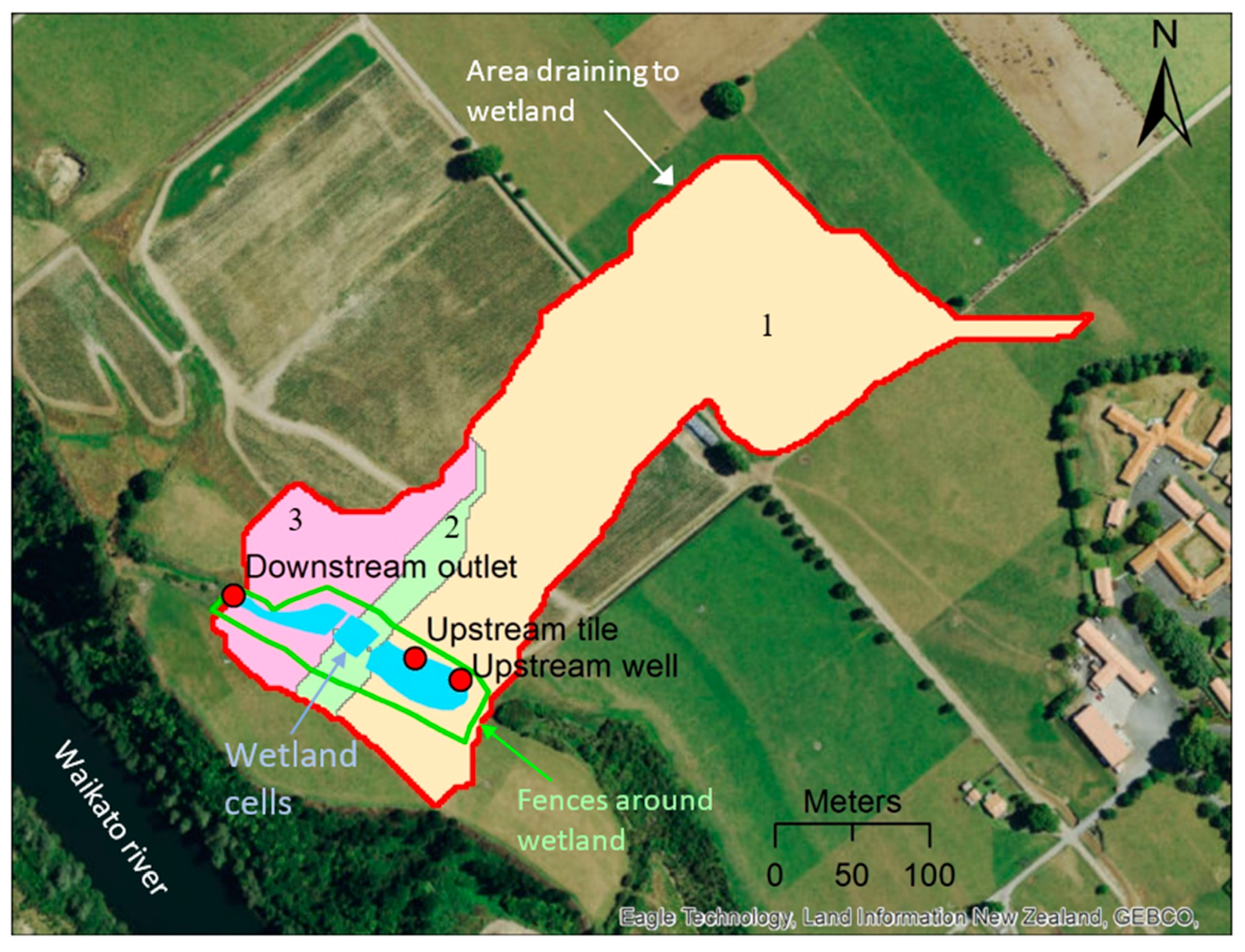
Figure 1. Owl Farm wetland, Cambridge, New Zealand, showing the 3 subcatchment areas draining to each cell of the wetland.
Water 15 01689 g001
Figure 2. Modelling framework linking the catchment model (SWAT) and the wetland model.
Water 15 01689 g002
Figure 3. Illustration of the division of the Owl Farm wetland catchment into hydrological response units (HRUs) in the SWAT model.
Water 15 01689 g003
Figure 4. Hydrological model for Owl Farm constructed wetland based on a tank-in-series approach. Blue color arrow means input to the system. Orange color arrow means loss from the system.
Water 15 01689 g004
Figure 5. Comparison of flow predictions and continuous flow measurements at the outlet of the Owl Farm constructed wetland.
Water 15 01689 g005
Figure 6. Comparison of SWAT predictions of nitrate and TN load versus measurements.
Water 15 01689 g006
Figure 7. Seasonal variation in flow components contributing to the wetland from 2017 to 2020.
Water 15 01689 g007
Figure 8. Seasonality of flow components versus nitrate load contributing to the wetland during the period 2017–2020.
Water 15 01689 g008aWater 15 01689 g008b
Figure 9. SWAT-predicted inflow versus outflow and theoretical hydraulic residence time of Owl Farm constructed wetland.
Water 15 01689 g009aWater 15 01689 g009b
Figure 10. Measured outflow nitrate-N concentration (with different types of sampling) versus simulated outflow of Owl Farm wetland.
Water 15 01689 g010
Figure 11. Variation in (a) nitrate-N and (b) TN concentration versus wetland inflow. The blue bands in (b) highlight two events where TN concentrations at the downstream outlet were higher than at the upstream well.
Water 15 01689 g011
Figure 12. Boxplots of (a) nitrate-N and (b) TN concentration measured at the upstream well and tile sites, and at the downstream outlet.
Water 15 01689 g012
Figure 13. Model predictions of wetland nitrate-N in-load versus out-load.
Water 15 01689 g013
Figure 14. Nitrate-N-load reduction (in kg/ha/day) estimated by (i) approach I: based on the measured concentration and simulated flow in sampled days, and (ii) approach II: based fully on model predictions.
Water 15 01689 g014
Figure 15. Relationship between percentage of nitrate-N-load removal, simulated wetland outflow, and hydraulic residence time using two approaches: (i) approach I: based on the measured concentration and simulated flow in sampled days, and (ii) approach II: based fully on model predictions.
Water 15 01689 g015
Figure 16. Temporal variation in nitrate-N load removal (in %) versus wetland outflow using two approaches.
Water 15 01689 g016
Figure 17. Tank-in series nitrate mass balance in the Owl Farm wetland.
Water 15 01689 g017
Table 1. Dimensions of Owl Farm wetland cells and their drainage areas.
Wetland CellWetland Area (m2)Average Depth (m)Volume of Tanks (m3)Catchment Area (ha)
Cell 119000.35705.47
Cell 24500.31350.44
Cell 36000.31801.16
Sum2950 8857.07
Table 2. Flow and water-quality monitoring in the Owl Farm wetland.
Type of SamplingNumber of SamplesVariables
Upstream WellUpstream TileDownstream Outlet
Monthly grab sampling261524NOx-N, NH4-N, TN
Event sampling3 events5 events6 eventsNOx-N, NH4-N, TN
(65 samples)(64 samples)(126 samples)
High frequencynonenone2017–present, with some data gapsFlow, NOx-N
Table 3. Nutrient input to the Owl Farm wetland catchment.
ActivityNutrient SourcesEstimating Method/Information SourceNitrogen Input
(kg N/ha/Year)
GrazingManure from dairy-cow grazingNumber of dairy cows/ha × amount of
manure/cow × %N in manure
Data from farm surveys and the agricultural waste manual [43]
266
Fertilizer
application
Fertilizer applicationInformation from Owl Farm database133
Application of dairy shed
effluent to land
Information from Owl Farm database46
Atmospheric
deposition
Dry depositionParfitt et al. [42] reported 5–10 kg N/ha7.5
(50% NH4-N, 50% NOx-N)
Wet depositionParfitt et al. [42]1.5
(50% NH4-N, 50% NOx-N)
Table 4. Calibrated parameters in the SWAT and wetland model for hydrological and nitrogen simulation.
NameUnitDefinitionRangeCalibrated Value
Hydrology
SWAT parameters
CN2-SCS runoff curve number for moisture condition II−0.25–0.25 *−0.24
ALPHA_BFday−1Base flow recession constant0–10.99
ESCO-Soil evaporation compensation factor0–10.109
EPCO-Plant water uptake compensation factor0–10.663
SOL_AWCmm/mmAvailable water capacity of the soil layers−0.25–0.25 *0.057 *
SOL_ZmmDepth from soil surface to bottom of the soil layer−0.25–0.250.061 *
SOL_Kmm/hSaturated hydraulic conductivity−0.25–0.250.19 *
SURLAGhoursSurface runoff lag time0–2419.450
TDRAINhoursTime to drain soil to field capacity12–4831.273
GDRAINhoursDrain tile lag time12–4822.317
Wetland model parameters
ETcoeff-Evaporation coefficient0–10.832
Nitrogen simulation
SWAT parameters
RSDCOmmResidue decomposition coefficient0.02–0.10.054
NPERCO-Nitrate percolation coefficient0–10.382
N_UPDIS-Nitrogen uptake distribution parameter0–10045.915
SDNCO-Denitrification threshold water content1–1.21.1
CDN-Denitrification exponential rate coefficient1–21.723
SHALLST_NmgN/LInitial concentration of nitrate in shallow aquifer6.5–1513.658
FIXCO Nitrogen fixation coefficient0–10.097
Wetland model parameters
kN,20m/dayNitrogen removal rate at water temperature at 20 °C0.05–0.50.055
Ɵ-Temperature coefficient1–21.012
Note: * Parameter that is changed by multiplying the original value by (1 + calibrated value). The original value is usually the default value.
Table 5. Water balance of the Owl Farm wetland catchment (April–March for each monitoring year during 2017–2021).
Water Balance Components2017–20182018–20192019–2020Annual Average
mm/Yearmm/Yearmm/YearWater Depth (mm/Year)Percentage of Flow Components (%)
Precipitation1295979718997
Evapotranspiration709704576663
Surface runoff2430.192.7
Tile flow13678358324.9
Groundwater4262208024272.4
Table 6. SWAT-predicted nitrogen load driven by different flow components to the wetland.
Nitrogen Loss to the Wetland (kg N/ha/Year)2017–20182018–20192019–2020Annual Average
Organic N loss by erosion6.52.60.93.3
Nitrate-N loss to the wetland45.626.79.727.3
  • Through surface runoff
0.30.10.020.14 (0.3%) *
  • Through tile drainage
5.25.04.34.8 (17.6%) *
  • Through groundwater flow
40.121.65.422.4 (82.1%) *
Note: * the percentage number in () shows the percentage of nitrate-N load contributed from different flow pathways.
Table 7. Nitrate-removal efficiency of the Owl Farm wetland.
Variables2017–20182018–20192019–2020Annual Average
Nitrate load entering the wetland (kg/year)310.8182.267.2186.7
  • From catchment
309.5180.965.8185.4
  • From atmospheric deposition
1.31.31.41.3
Nitrate load at wetland outlet (kg/year)134.062.011.169.0
Nitrate loss through infiltration to the bottom of the wetland (kg/year)6.94.71.94.5
Nitrate removed in the wetland (kg/year)169.9115.554.2113.2
Annually nitrate load removal rate (%)54.763.480.460.6
Disclaimer/Publisher’s Note: The statements, opinions and data contained in all publications are solely those of the individual author(s) and contributor(s) and not of MDPI and/or the editor(s). MDPI and/or the editor(s) disclaim responsibility for any injury to people or property resulting from any ideas, methods, instructions or products referred to in the content.