Article

Integrated Time-Dependent Analysis of a Hydraulic Structure on Soft Foundations during Construction

1
School of Civil Engineering and Architecture, Zhejiang University of Science and Technology, Hangzhou 310023, China
2
Zhejiang-Singapore Joint Laboratory for Urban Renewal and Future City, Hangzhou 310023, China
3
School of Water Conservancy and Environment Engineering, Zhejiang University of Water Resources and Electric Power, Hangzhou 310018, China
4
Department of Hydraulic Engineering, Zhejiang Tongji Vocational College of Science and Technology, Hangzhou 311231, China
*
Author to whom correspondence should be addressed.
Water 2024, 16(10), 1375; https://doi.org/10.3390/w16101375
Submission received: 19 March 2024 / Revised: 26 April 2024 / Accepted: 9 May 2024 / Published: 11 May 2024

Abstract

:
An integrated model that considers multiphysics is necessary to accurately analyze the time-dependent response of hydraulic structures on soft foundations. This study develops an integrated superstructure–foundation–backfills model and investigates the time-dependent displacement and stress of a lock head project on a soft foundation during the construction period. Finite element analyses are conducted, incorporating a transient thermal creep model for concrete and an elasto-plastic consolidation model for the soil. The modified Cam-clay model is employed to describe the elasto-plastic behavior of the soil. Subsequently, global sensitivity analyses are conducted to determine the relative importance of the model parameters on the system’s response, using Garson’s and partial derivative algorithms based on the backpropagation (BP) neural network. The results indicate that the integrated system exhibits pronounced time-dependent displacement and stress, with dangerous values appearing during specific periods. These values are easily neglected, highlighting the importance of integrated time-dependent analysis. Construction activities, particularly the backfilling process, could cause a sudden change in stress and significantly impact the stress redistribution of the superstructure. Additionally, the mechanical properties of concrete have a significant impact on the stress on the superstructure, while the mechanical properties of the soil control the settlement of the integrated system.

1. Introduction

In coastal and plain areas, the predominant soil type is typically soft soil; in particular, coastal areas are characterized by abundant soils with high water content and low permeability [1]. Hydraulic projects in these regions are often built along coastlines, such as tidal barriers, or within river channels, such as ship locks. Therefore, they can collectively be referred to as hydraulic structures on soft foundations. These projects are usually considered as an integrated system consisting of three main subsystems: the concrete superstructure, soft soil foundation, and backfilled soil. The interactions between these three subsystems are highly complex. Notably, the load from the superstructure influences the pore water pressure and consolidation settlement of the soil [2]. Simultaneously, the deformation of the soil influences the redistribution of stress in the concrete superstructure [3]. Such a sophisticated system should have integrated analysis to improve its design. Each subsystem has various time-dependent physical fields, such as the transient temperature field and creep deformation in the concrete structure, as well as the pore water pressure and consolidation deformation in the soft soil. These fields contribute to the complexity of the entire project, representing a sophisticated system with a time-dependent process arising from multifield coupling. Consequently, analyses with simplified load and boundary conditions under a limited number of severe load cases cannot comprehensively assess the deformation and stress response of the entire system [4]. This approach proves inadequate to accurately assess the safety of hydraulic structures on soft foundations, particularly during the construction phase, when the complexity of physical field coupling is most significant.
Researchers and engineers have acknowledged the interactions between the structure and soil, as well as their influence on project analyses. Initially, it was challenging to consider the effects of interactions, due to limitations in analytical theories and solution methods. Subsequently, researchers proposed the elastic foundation beam method [5], which considers the coordinated deformation at the interface between the beam structure and the elastic foundation, as well as the stiffness of the structure. However, this method did not account for the influence of the stiffness of the superstructure above the beam on the deformation of the superstructure–beam–foundation system, or the time-dependent effects of the system. Later, soil models that accounted for consolidation settlement or viscoelastic deformation were incorporated into the foundation beam method to analyze the system’s time-dependent variations, thereby obtaining historical deformation and stress information. For instance, Elhuni et al. [6] employed a viscoelastic foundation model to analyze the dynamic deformation of Euler–Bernoulli beams resting on multilayered soil under oscillating moving loads, and they obtained a time-dependent response to the problem. Simultaneously, Elhuni et al. [7] also utilized Biot’s consolidation theory to study the consolidation settlement of flexible foundations on porous elastic layered soil. Lanes et al. [8] combined the boundary element method, Mindlin’s fundamental solution, and Terzaghi’s consolidation theory to analyze the response of viscoelastic soil–structure interaction for foundations and frame structures on soft soil. With advancements in computational technology and numerical analysis software, complex numerical models can now be seamlessly integrated into analysis frameworks to consider the impact of the superstructure’s stiffness on the superstructure–foundation–soil system. For example, Ai et al. [9] connected the stiffness matrices of the superstructure and slab using substructure technology. They employed a boundary element–finite element coupling method to investigate the time-dependent response of the interaction between the slab and viscoelastic saturated soil. Gorini et al. [10] developed a comprehensive system model for the soil–abutment–superstructure in bridge projects to analyze the impact of the local dynamic response of the bridge abutment on the entire system. Simultaneously, more advanced constitutive models, such as elastoplastic soil models and fractional models, have been introduced into numerical analyses to better understand complex system responses. For example, Ai et al. [11] used a fractional viscoelastic cross-anisotropic saturated soil model to analyze the time-dependent behavior of the interaction between the soil and slab. Shamsi et al. [12] conducted a nonlinear analysis of the interaction between factors such as topography, structure, and soil that affect buildings near slopes. They utilized an elastoplastic hysteretic model with anisotropic hardening.
With contributions from previous research advancements, as indicated by the literature mentioned above, the mechanism and degree of influence of the interactions between the soil and structure have been progressively revealed, significantly enhancing the effectiveness and accuracy of analysis. However, for hydraulic structures characterized by significant concrete consumption, which are typically massive concrete structures often surrounded by backfilled soil to enhance stability, the analysis during the construction stage needs to consider factors such as transient thermal stresses and concrete creep, as well as the impact of backfills on the system. Duncan et al. [13] conducted research using the finite element method to study the deformation and stress response of the structure–backfill–foundation system of the Port Allen lock throughout the entire construction process in its early stages. However, this study did not take into account the consolidation process of the subsoil and the thermal creep stress of the concrete. More related studies, such as the one by Rui et al. [14], have primarily focused on the interactions between backfills and retaining walls, without effectively integrating them into the soil–structure system for comprehensive analysis. The literature review reveals a lack of comprehensive research on various interactions in hydraulic structures. In bridge engineering, research on the integral bridge system [15] has focused on soil–structure interaction, thermal loads, concrete creep and shrinkage, and the influence of backfilled soil [16]. Therefore, it is essential to extract valuable insights from such research and conduct integrated studies on hydraulic structures constructed on soft foundations.
To explore the time-dependent behavior of hydraulic structures on soft foundations under multiphysics and complex interactions, this study uses a lock head project as a case study and establishes an integrated superstructure–foundation–backfills system. The lock head’s floor has a large contact area with the foundation, and there is extensive contact between the sidewalls and backfilled soil. Simultaneously, this system exemplifies a typical multifield coupled system, involving factors such as the temperature field, the creep thermal stress field of concrete, and the seepage field of the soil. The deformation and stress development of the entire system can be influenced by these fields. This study constructs an integrated finite element model that includes the lock head, foundation, and backfills. Initially, the transient temperature field of this system is calculated during the construction phase. Subsequently, an integrated numerical analysis is conducted based on the thermal results, considering concrete creep and a coupled elasto-plastic consolidation that incorporates Biot’s consolidation theory and the modified Cam-clay model. Furthermore, to investigate the influence of calculation parameters on the deformation and stress of this system, a global multi-parametric sensitivity analysis of the mechanical parameters of concrete and soil is conducted. The sensitivity analysis can assess the relative importance of model parameters on results [17]. Currently, various methods such as grey theory [18], particle swarm optimization algorithm [19], and BP neural network [20] have been used for parametric sensitivity analysis. In this study, sensitivity analyses are conducted using the partial derivative and Garson’s algorithm based on the BP neural network. These two methods mainly employ the intrinsic topological structure and parameters of the neural network, leading to better interpretability compared to other methods. The structure of this paper is organized as follows: Section 2 briefly introduces the main mathematical and physical equations used in the integrated numerical model to illustrate how multifield are considered in this study. Section 3 provides a detailed description of the lock head project, including basic geometric information, calculation parameter values, and the construction process considered in the time-dependent analysis. Section 4 demonstrates and discusses the results, focusing on the deformation and stress variation of the structure over time, as well as the findings of the parameter sensitivity analysis. Section 5 presents the primary conclusions of the current study.

2. Methods

2.1. Physical Equations for Finite Element Analyses

The transient temperature distribution of the concrete–foundation–backfills system is calculated initially as the basis for solving the stress states of this system. The governing equation for transient thermal calculation is as follows [21]:
c ρ T t = k 2 T x 2 + 2 T y 2 + 2 T z 2 + Q ( t ) t
where T is the temperature; t is the time; x, y, and z are spatial coordinates; k is the thermal conductivity coefficient; c is the specific heat capacity; ρ is the mass density; and Q(t) represents the accumulated hydration heat of concrete at time t, and it equals zero for soil.
In hydraulic projects, the commonly considered boundary condition is the convection phenomenon, which can be expressed as follows:
k T n = β T T a
where n denotes the normal direction of the surface; β represents the surface heat transfer coefficient; and T a refers to the environmental temperature.
For transient thermal calculations, the initial condition specified below in Equation (3) should also be considered.
T 0 x , y , z = T x , y , z , t = 0
After calculating the temperature, the thermal strain can be determined using the following formula:
ε T = α Δ T   α Δ T   α Δ T   0   0   0
where ε T represents the thermal strain vector; ΔT denotes the temperature difference; and α is the thermal expansion coefficient.
Stress induced by thermal strain is calculated using the creep model described by Equations (5) and (6), as follows:
E τ = E 0 1 exp a τ b
C t , τ = s = 1 ψ s τ 1 exp r s t τ
where E(τ) and C(t,τ) represent the ultimate elastic modulus and unit creep, respectively; τ denotes the loading time, while t is the calculation time; E 0  stands for the ultimate elastic modulus of the concrete; and other parameters are the material constants that have been tested.
In the mechanical simulation phase during construction, consolidation calculations are carried out for soil using Biot’s three-dimensional coupled theory [22], which is based on the effective stress principle and Darcy’s law. The governing equations are as follows:
G 2 u 3 K + G 3 ε v x p x + f x = 0 G 2 v 3 K + G 3 ε v y p y + f y = 0 G 2 w 3 K + G 3 ε v z p z + f z = 0 ε v t + k s γ w 2 p x 2 + k s γ w 2 p y 2 + k s γ w 2 p z 2 = 0
where u, v, and w are displacements; ε v  represents the volumetric strain; K denotes the volumetric modulus; G is the shear modulus; p signifies the pore pressure; f x , f y , and  f z  are volumetric forces;  k s  is the soil permeability coefficient; and  γ w  represents the unit weight of water.
The boundary and initial conditions of the pore pressure are described in Equations (8) and (9), as follows:
p = 0   on   drainage   surface p n = 0   on   non - drainage   surface
p 0 x , y , z = p x , y , z , t = 0
In this paper, the modified Cam-clay (MCC) model [23,24] is adopted to accurately demonstrate the behavior of soil in terms of stress–strain relationships. The MCC model is an elasto-plastic model with the yield function of Equation (10). Theoretical details can be found in the relevant literature [25,26,27].
p p c 2 + q M 2 = p c 2 2
where p is the mean effective stress; q is the deviator stress; M represents the slope of the critical state line in the p q plane as shown in Figure 1; and p c is the preconsolidation pressure.

2.2. Backpropagation (BP) Neural Network with One Hidden Layer

A BP neural network, which is short for error backpropagation neural network, is a commonly used type of neural network in engineering [28]. It has been proven that any nonlinear relationships can be approximated using a two-layer perceptron network [29]. Hence, the one-hidden-layer backpropagation (BP) neural network, as demonstrated in Figure 2, is utilized in this paper.
The output of a node in the BP neural network can be calculated using Equation (11) according to the inputs, weights, and thresholds of the layer to which the node belongs, as follows:
o u t j = f i w i j i n i + θ j
where o u t j is the output value of the jth output node in this layer; i n i is the input value of the ith input node in this layer; w i j is the weight that connects the ith input node and the jth output node; θ j is the threshold of the jth output node; and f represents the transfer function of this layer.
There are various types of transfer functions in the BP neural network, including the threshold function, piecewise linear function, sigmoid function, and hyperbolic tangent function. The sigmoid function is adopted as the transfer function in this study due to its advantageous derivative format, as shown in Equations (12) and (13) below:
f x = 1 1 + e x
f x = f x 1 f x

2.3. Global Sensitivity Analysis Methods Based on Backpropagation (BP) Neural Network

Nowadays, there are various types of sensitivity analysis methods, such as derivative-based, distribution-based, variogram-based, regression-based, and response surface-assisted approaches [30]. In this paper, two methods based on the BP neural network are employed for sensitivity analysis.

2.3.1. Garson’s Algorithm

Garson’s algorithm is a widely used method for sensitivity analysis by many researchers [31]. This method estimates the relative importance of input variables to output variables [32]. Goh [33] improved this method to enhance its applicability to complex systems, as follows:
Q i k = j = 1 m W i j T j k / r = 1 l W r j i = 1 l j = 1 m W i j T j k / r = 1 l W r j
where Q i k is the sensitivity coefficient that represents the relative importance of the ith input variable to the kth output variable.
Sensitivity coefficients calculated using Garson’s algorithm are less than 1.0, and the sum of all sensitivity coefficients in a system equals 1.0. Therefore, the results obtained using this method can be considered as the influence weights of input variables on output variables. However, some comparative studies show that the results from Garson’s algorithm may not be very reliable [34]. Therefore, the partial derivative algorithm is also utilized in the current study.

2.3.2. Partial Derivative Algorithm

The convenient calculation of the derivative of the sigmoid function, with respect to the input variable, enables the easy derivation of the analytical partial derivative expression of output variables, with respect to input variables in the BP neural network.
According to the chain rule, the partial derivative of the output variable o k , with respect to the input variable x i , is as follows:
o k x i = j = 1 m o k y j y j x i
The right-hand side of Equation (15) can be expanded to Equation (16), according to Equation (13).
o k y j = T j k o k 1 o k y j x i = W i j y j 1 y j
Then, the formula to calculate the sensitivity coefficients can be obtained as in Equation (17).
o k x i = o k 1 o k j = 1 m T j k W i j y j 1 y j

2.4. Comprehensive Research Flow

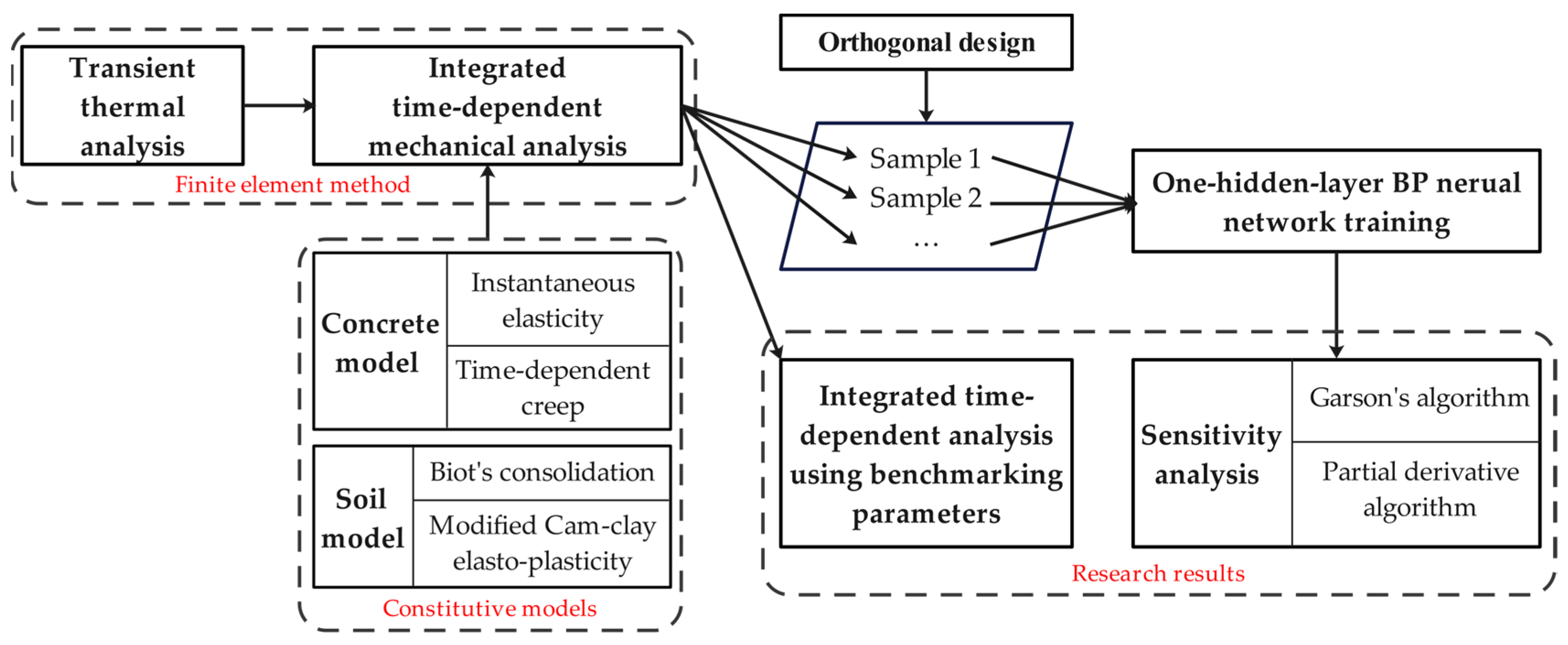
Figure 3 comprehensively illustrates the research flow, which primarily consists of the following steps:
(1) The “finite element method” block is the core of this integrated time-dependent analysis, utilizing the governing equations and constitutive models described in Section 2.1. Initially, transient thermal analysis is conducted to calculate the temperature field of the integrated model, which serves as the foundational data for subsequent mechanical analysis. Subsequently, an integrated time-dependent mechanical analysis is conducted. Concrete utilizes instantaneous elastic and transient thermal creep models, while the soil incorporates Biot’s consolidation theory and an elasto-plastic model based on the modified Cam-clay model, as depicted in the “constitutive models” block of Figure 3.
(2) By employing the integrated time-dependent mechanical analysis method, a time-dependent analysis of the integrated model is conducted using benchmarking parameters. The results are then analyzed to study the time-dependent deformation and stress evolution of the hydraulic structure on soft foundations, as indicated in the left part of the “research results” block in Figure 3.
(3) The orthogonal design method is employed to create multiple samples for sensitivity analysis, where the parametric levels in the orthogonal design are multiples of the benchmark parameters. Each sample is computed using the integrated time-dependent mechanical analysis method, and then complete sample data are obtained for training the BP neural network with one hidden layer. Subsequently, the parameters of the BP neural network are obtained.
(4) Based on the trained network parameters, a sensitivity analysis of the mechanical parameters in the integrated time-dependent mechanical analysis is conducted using Garson’s and partial derivative algorithms to assess the influence of each parameter on the results (the displacement and stress), as illustrated in the right part of the “research results” block in Figure 3.

3. Project Background

3.1. Project Overview

A ship lock head constructed on a soft foundation is used as a validation case in this study. The total length of the lock head structure along the river is 28.5 m, and the total width across the river is 53.8 m. The total height of the lock head is 11.9 m, and the height of the floor is 2.6 m.
The foundation pit for this project was excavated in two steps with varying slope coefficients, and a platform was installed between the two steps. The size parameters and slope coefficients are shown in Figure 4.
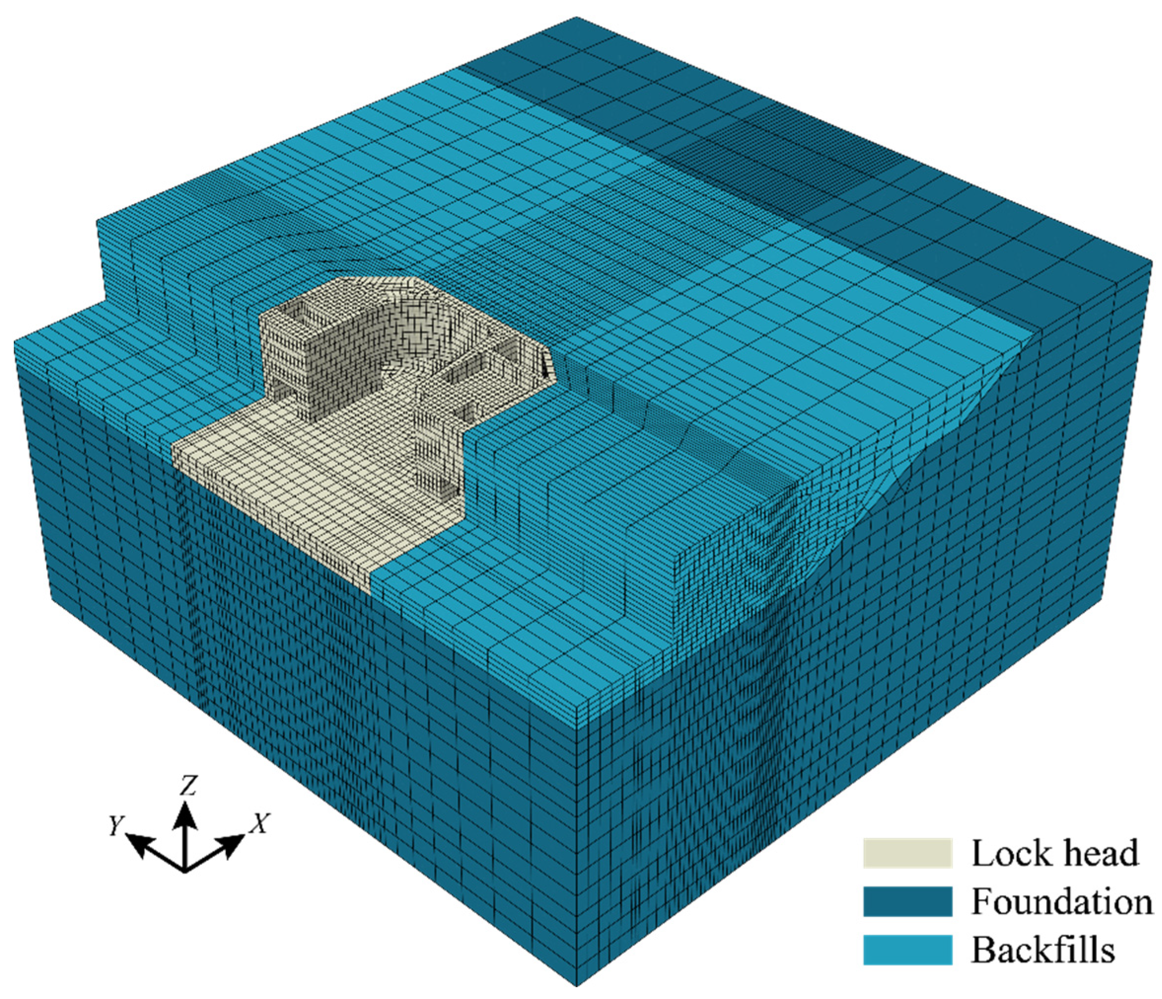
Structural concrete was cast in three main parts, from bottom to top: (1) the floor; (2) from the top of the floor to the bottom of the hollow box section; and (3) from the bottom of the hollow box section to the top of the head. The backfilling process was also divided into three layers, and the elevations of the top surfaces of the three layers from bottom to top were consistent with the corresponding concrete parts. Concrete was cast in batches and layer by layer. The complete construction process, including concrete casting and soil backfilling, is detailed in Table 1. Overall, the total simulation duration is 377 days. The finite element mesh for the numerical analysis of the concrete–foundation–backfilling system is illustrated in Figure 5.

3.2. Material Properties

3.2.1. Thermal Parameters

For thermal calculations during construction, the thermal properties of concrete and soil are provided in Table 2. The temperature distribution of the subsoil was calculated for several decades prior to the start of floor casting, taking into account the excavation of the foundation pit. The calculated results were then used as the initial subsoil temperature to simulate the project. The initial temperature of the backfilled soil was 15 °C. The initial temperatures of the three concrete parts mentioned in Section 3.1 were 15 °C, 30 °C, and 20 °C, respectively.
Figure 6 illustrates the fluctuation of environmental temperature throughout the calculation period. The adiabatic temperature rise model for concrete lock heads is defined as follows:
θ τ = 51.034 1 exp 0.701 τ 1.067
where θ τ represents the adiabatic temperature of concrete at age τ.

3.2.2. Mechanical Parameters

The subsoil beneath the lock head is complex, showing apparent stratifications. According to the prospecting reports, the subsoil can be divided into nine layers for analysis. In this paper, the MCC model is utilized to describe the behaviors of subsoil and backfilled soil. Therefore, the initially anticipated soil properties were transformed into parameters of the MCC model using regression formulas developed by Chen et al. [35], and then slightly adjusted based on other investigations [36,37,38,39]. The converted MCC model parameters are listed in Table 3, along with other parameters for calculation, such as initial status parameters, permeability coefficients, and mechanical parameters in Table 4. The calculation parameters of the first layer are used for the backfilled soil. The Poisson’s ratios of the subsoil and backfilled soil are both 0.3.
In Table 3 and Table 4, ρ represents the mass density; λ denotes the slope of the critical state line in the e ln p plane, where e is the void ratio of the soil; κ stands for the slope of the unloading–reloading line in the e ln p plane; K 0 signifies the static lateral earth pressure coefficient; p c 0 indicates the initial yield stress of the soil, OCR refers to the over-consolidation ratio of the soil; and  c u  is the undrained shear strength of the soil.
The expansion coefficients of concrete and soil are 0.9 × 10 5 /°C. The mass density of concrete is 2400 kg/m3, and its Poisson’s ratio is 0.167. The elastic modulus and unit creep of the locking head concrete are expressed by Equations (19) and (20), with E 0 set at 34,250 MPa.
E τ = E 0 1 exp 0.4 τ 0.34
C t , τ = 0.23 E 0 1 + 9.2 τ 0.45 1 exp 0.3 t τ +                                     0.52 E 0 1 + 1.7 τ 0.45 1 exp 0.005 t τ
According to Equations (19) and (20), the elastic modulus E and the unit creep C of concrete can be controlled by the parameter E 0 . As a result, parameters E and C are considered to vary together. Numerous laboratory investigations have proven that the parameters λ and κ in the MCC model have an approximate relationship (κ ≈ 0.1λ). Therefore, the parameters λ and κ can also be considered as a group of parameters that can vary together. Additionally, the permeability coefficient k s of soil is a parameter that varies independently.

3.3. Sample Design for Sensitivity Analysis

Three different parameter groups (E and C, λ and κ, and k s ) are set at three levels (0.9, 1.0, and 1.1), where the level of 1.0 means that the values of parameters are the same as the aforementioned values in this section, and combined using the orthogonal design method. Four samples with different level parameter groups can be obtained, as listed in Table 5, for the global sensitivity analysis of this project.

4. Results and Discussion

Several characteristic points on the floor and main structure of the lock head are defined, as shown in Figure 7, to investigate stresses and deformations of concrete and soil. D1~D6 points are used for analyzing the settlement of the top surface of the subsoil. The variations in the maximum principal stress on the top surface of the floor, the side wall of the water corridor section and the side wall of the hollow box section are described on S1~S6, LD-1 and LD-2 and KX-1 and KX-2 points, respectively.
As this study focuses on the variation in displacement and stresses in soil and structure, temperature results are not presented here.

4.1. Variation in Displacement and Stress over Time

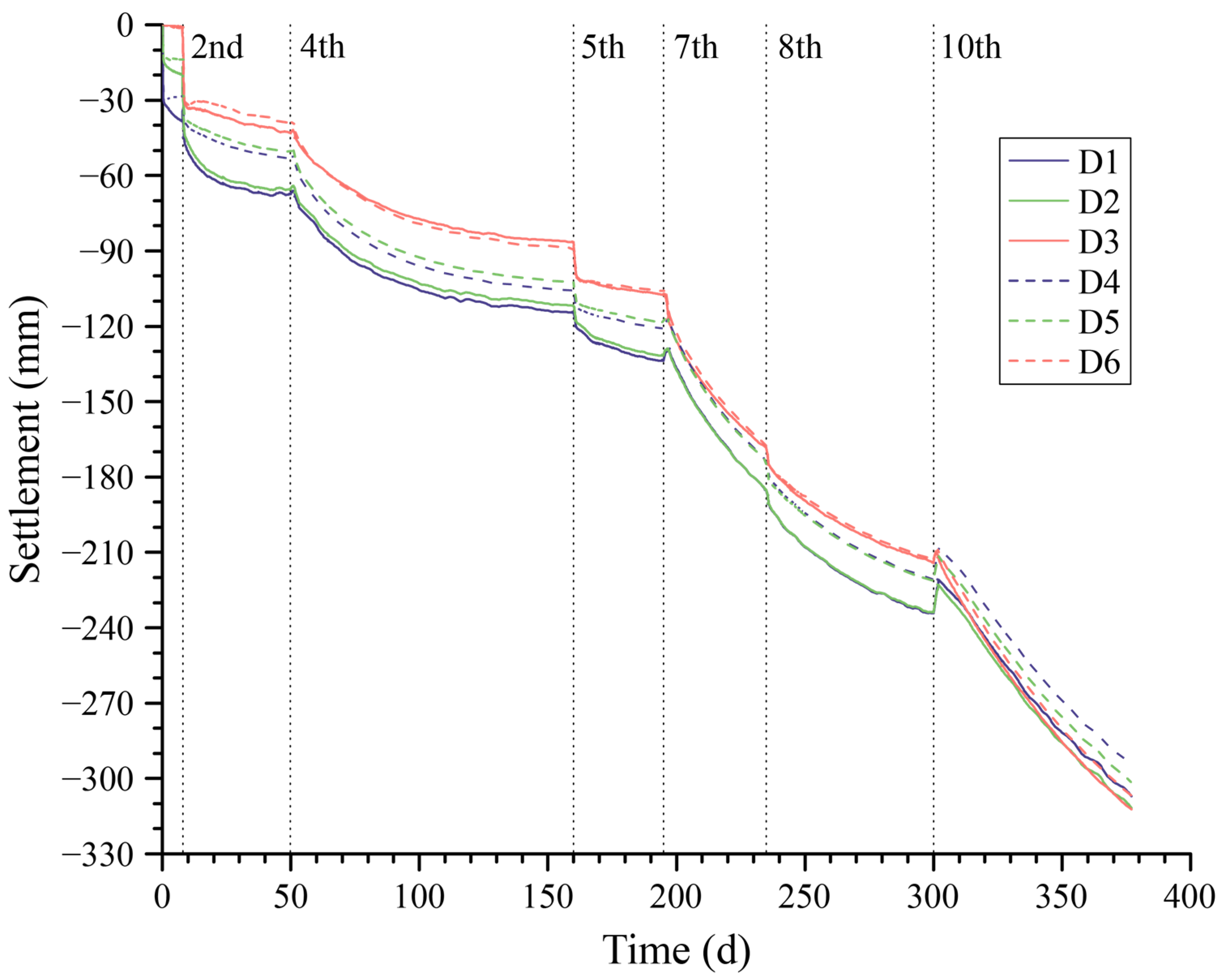
The settlements of D1~D6 points are illustrated in Figure 8. It is obvious that the settlement of the foundation surface depends on time. The foundation surface is impermeable during construction; therefore, external loads will generate a significant amount of excess pore pressure that cannot dissipate quickly, leading to increased resistance against external loads. As a result, the instantaneous settlement is small. Even after the completion of backfilling a soil layer, the excessive pore pressure resulting from the weight of the backfilled soil will cause a rebound displacement on the foundation surface, as illustrated in Figure 8 on the 4th, 7th, and 10th lines. The settlement varies with the dissipation of excess pore pressure, and the settlements of central points (D1 and D2) are larger than those of the side points (D3~D6).
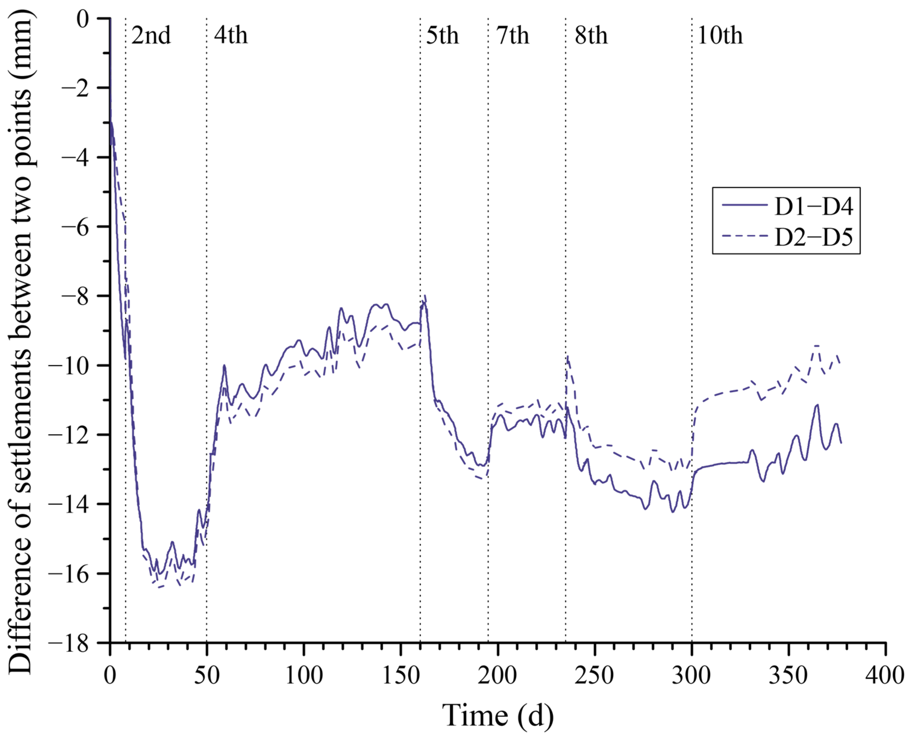
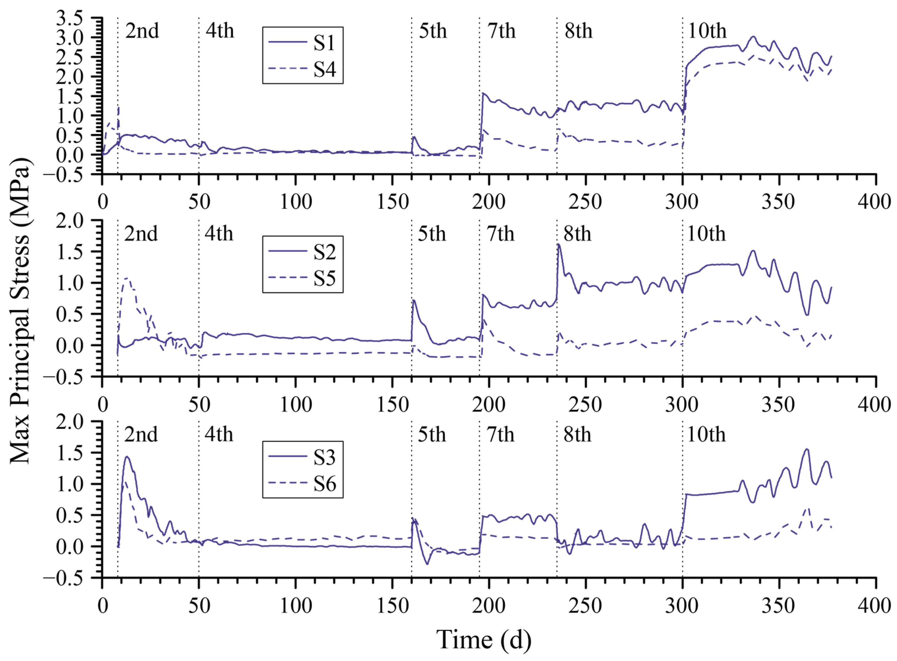
Figure 9 and Figure 10 illustrate the differences of settlements between the center line and the boundary line of the floor’s bottom surface across the river, as well as the variation curves in the maximum principal stress at points S1~S6 on the upper surface of the floor over time, respectively. In Figure 9, the center line is defined by points D1 and D2, while the boundary line is defined by points D4 and D5. Due to the consolidation of the foundation, settlement differences vary continuously throughout the entire calculation period. The variation range is mainly from 8 mm to 16 mm. This phenomenon leads to the redistribution of stress over time in the superstructure, as shown in Figure 10. Stress variations at both the center and boundary points, aligned along the same line in the river direction, exhibit a similar pattern, as depicted in each subfigure of Figure 10. Construction activities, such as pouring concrete structures and backfilling soil, have a significant impact on the displacement and the stress due to the generated external load, as illustrated on both sides of every step line in these two figures. Meanwhile, the stress at boundary points (points S3, S4, S5, and S6) remains relatively stable due to less influence of the moment induced by the boundary load.
Furthermore, the curves following the 2nd, 5th, and 8th step lines in Figure 10 indicate a rapid stress reduction after the completion of the concrete superstructure construction. In contrast, after the completion of the backfilling process, the stress either experiences a slight decrease (as observed in the curve following the 4th and 7th step lines) or continues to increase (as observed in the curve following the 10th step line). Based on the analysis of stress variations, it is evident that the backfilling process has a more significant impact on the maximum principal stress of the floor’s top surface compared to the construction of the superstructure. Especially after the final backfilling process, the maximum principal stress at point S1, which is the center point of the floor’s upper surface, may exceed 3.0 MPa, resulting in cracks. This influence is attributed to the effects of the backfills on the pore pressure and settlement of the subsoil, which consequently result in stress changes within the superstructure.
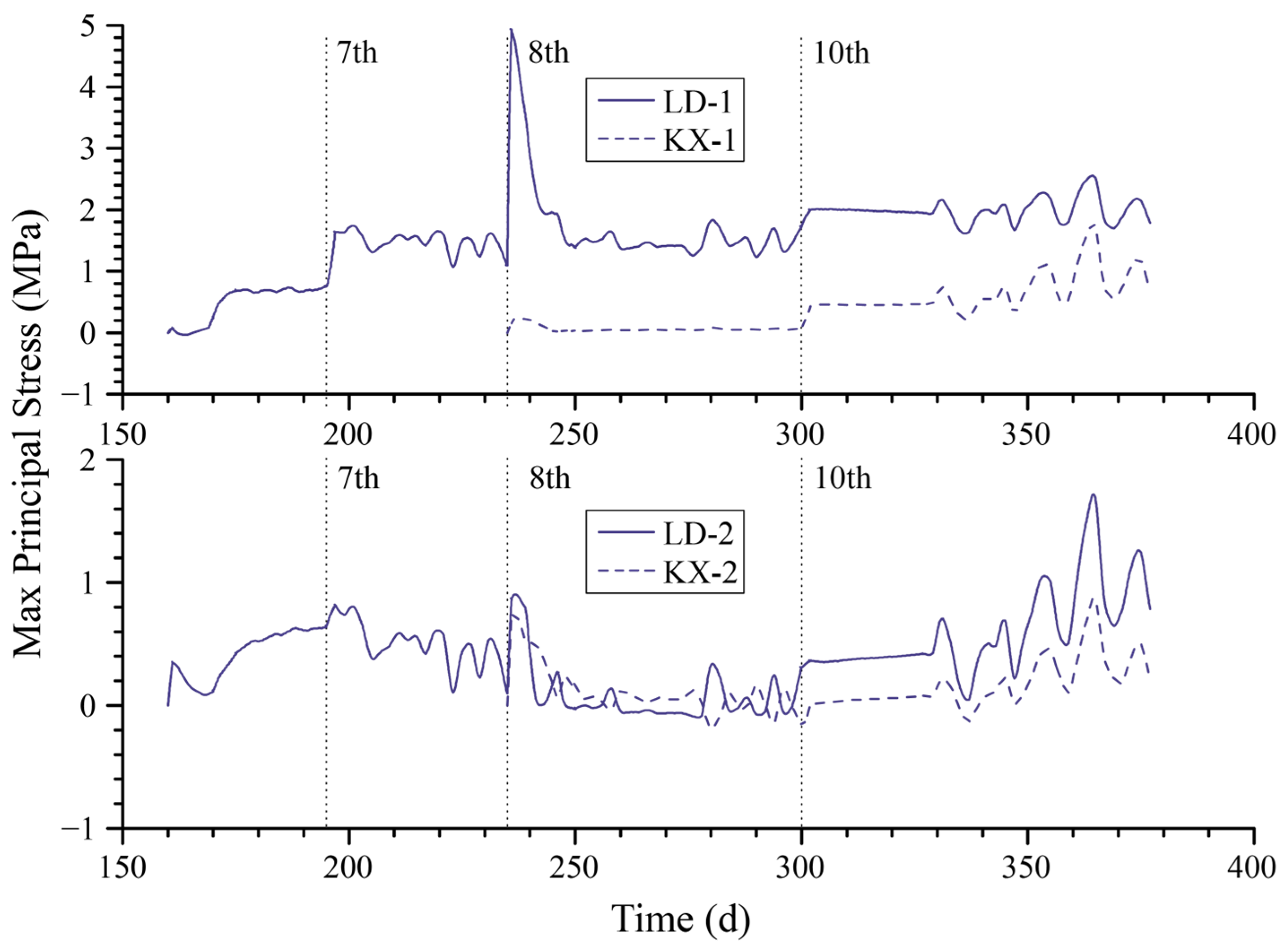
Variations in maximum principal stress at characteristic points on the sidewalls of the water corridor and hollow box sections are depicted in Figure 11. Points LD-1 and KX-1 correspond to locations on the sidewall along the river, while LD-2 and KX-2 represent points on the upstream sidewall across the river. Generally, the stress in the hollow box section is lower than that in the water corridor. Additionally, the stress difference between LD-1 and KX-1 points is greater than that between LD-2 and KX-2 points. Furthermore, it is observed that, in the water corridor and hollow box sections, the stress variations are significantly more affected by the concrete casting process than the backfilling process. Particularly, it is worth noting that there is a significant stress variation at point LD-1 during the construction of the hollow box (as indicated near the 8th step line), reaching nearly 4 MPa. This sudden change in stress requires attention during phases of design and construction.
The finite element analysis of the lock head project on a soft foundation notably demonstrates the time-dependent results of foundation settlement and the consequent stress variations in the superstructure. During the entire construction process, the applied external load generated from the concrete and backfills induces sharp variations in displacements and soil pore pressure, leading to significant settlements at the foundation surface and stress changes in the superstructure. The magnitude and impact of these changes should be paid attention to and investigated in practical engineering. It is crucial to evaluate these variations to determine necessary engineering measures for mitigating potential adverse effects in the actual construction project.

4.2. Global Sensitivity Analysis of Mechanical Parameters

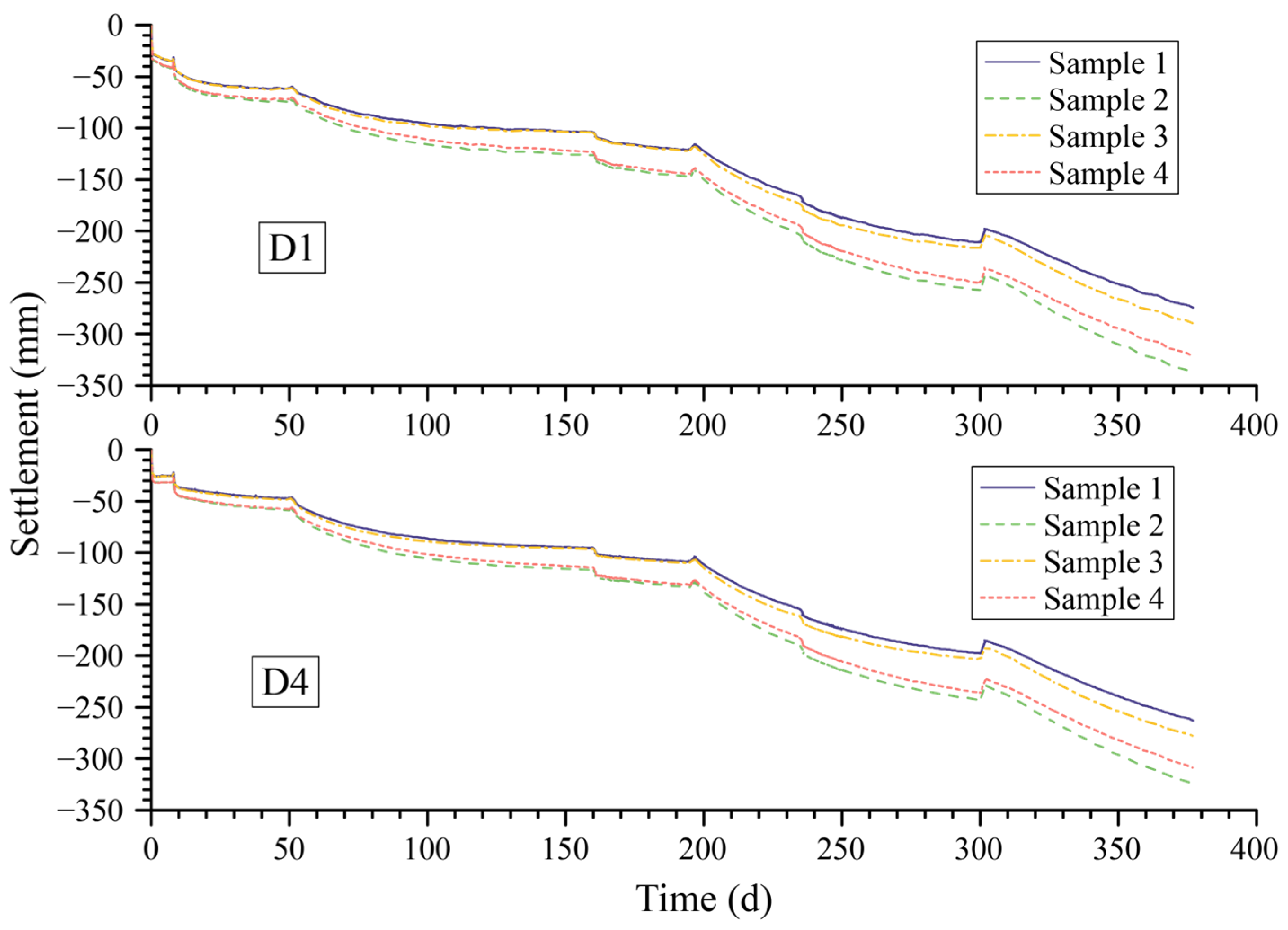
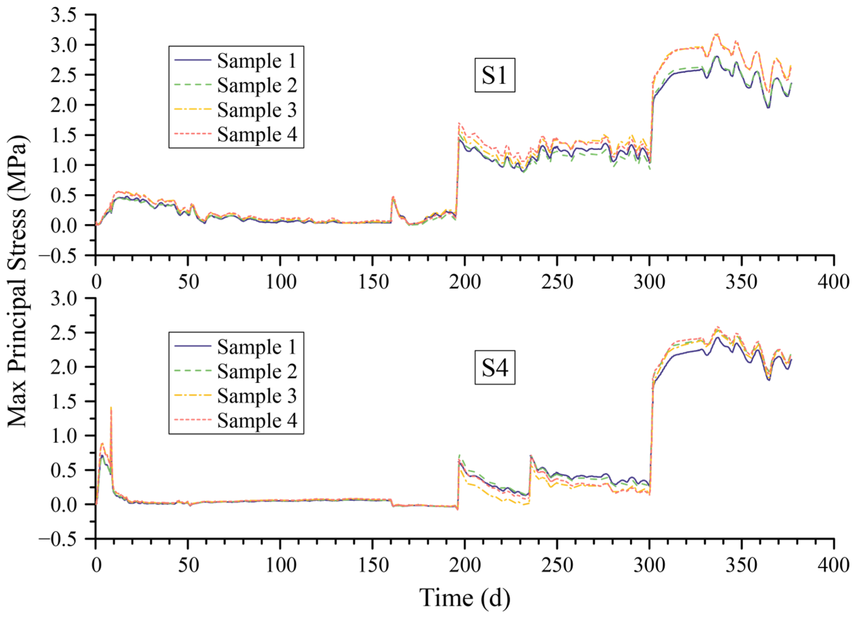
The settlement and maximum principal stress results obtained for the four designed samples in Section 3.3 at points D1, D4, S1, and S4 are shown in Figure 12 and Figure 13. It is evident that there are clear differences in the calculated results for the four samples. Therefore, this section conducts an in-depth analysis of the impact of multiple parameters to determine the importance of mechanical parameters on the results.
The maximum settlement values at the central point (D1) and boundary point (D4) on the foundation–soil interface, as well as the maximum principal stress values at the top center point (S1) and boundary point (S4) of the floor, have been extracted from the calculation results and are listed in Table 6. Sensitivity analyses of parameter groups were conducted using Garson’s method and the partial derivative method based on the BP neural network. The results of the sensitivity analysis are listed in Table 7 and Table 8.
The results from Table 7 and Table 8 indicate that the rankings of relative importance, based on sensitivity analyses from the two algorithms, are generally consistent. However, there are some differences in the maximum principal stress at point S1, although the determination of the most significant parameter remains consistent. The analysis results from both algorithms suggest that the soil model parameters (λ and κ) have the greatest impact on settlement calculations, with parameter λ having the most significant influence. On the other hand, the concrete model parameters (E and C) have the most significant impact on stress calculations of the superstructure. However, the relative importance rankings of parameters E and C on results at central and boundary points are slightly different. The parameter that has the greatest impact on results at central points is E, while at boundary points, the parameter with the greatest impact is C.
Moreover, the direction of the parameter’s influence on the results can be determined based on the sign of the results obtained from the partial derivative algorithm. According to the results, parameter C is negatively correlated with all the outcomes. This indicates that, as C increases, all the calculated results decrease. In contrast, the parameters κ and  k s  are positively correlated with the results. Furthermore, different parameters have varying effects on the calculation results. The parameter λ is generally positively correlated with all calculation results. On the other hand, the parameter E of concrete consistently shows a negative correlation with settlement and a positive correlation with stress in all scenarios.

5. Conclusions

This study investigates a lock head project to model and analyze the integrated superstructure–foundation–backfills system. The objective is to examine the time-dependent deformation and stress response of hydraulic structures constructed on soft foundations, taking into account multiphysics and complex interactions. The analysis begins with a transient temperature analysis of the system, followed by a mechanical analysis using time-dependent models. The concrete is modeled using a creep model, and the soft soil foundation undergoes elasto-plastic consolidation analysis using the modified Cam-clay model. Additionally, sensitivity analyses of important mechanical parameters are performed using Garson’s and partial derivative algorithms, which are based on the BP neural network. The main achievements of this study can be summarized concisely based on the conducted analyses, as follows:
  • The settlement and stress of the superstructure–foundation–backfills system on soft ground exhibit significant time-dependent characteristics. The settlement difference between the center line and the boundary line of the floor bottom surface primarily fluctuates within a range of 8 mm to 16 mm. The maximum principal stress at the center point on the upper surface of the floor would exceed 3.0 MPa after the final backfilling. Therefore, it is essential to conduct thorough checks and implement appropriate measurements to prevent cracks. The stress variation in the superstructure during the entire computation period is influenced by two factors: transient temperature stress and the continuous settlement of the foundation due to the consolidation of soft soil. Consequently, these factors affect the redistribution of stress in the superstructure. Therefore, when conducting an internal force analysis of hydraulic structures on soft foundations, it is essential to consider the time-dependent interactions.
  • The addition of backfilled soil increases the gravitational load on the foundation pit, causing immediate settlement and an increase in pore water pressure within the subsoil. This increase in pore water pressure prolongs the consolidation process. These immediate and time-dependent processes significantly affect the displacement of the foundation surface, resulting in a sudden change that can reach nearly 4 MPa in the water corridor section and subsequent redistribution of stress in the superstructure. Moreover, when analyzing the structure, it is crucial to carefully consider the stress growth resulting from this sudden change in order to ensure a more accurate assessment of structural safety.
  • Garson’s method and the partial derivative algorithm, both based on the BP neural network, can provide a global sensitivity analysis for parameters and their respective rankings of relative importance. The outcomes of these two methods exhibit general consistency, with minor differences that do not have a significant impact on the main findings. This highlights the practicality of using both algorithms to conduct global sensitivity analyses in hydraulic structures on soft foundations. Moreover, the partial derivative algorithm provides insights into the specific direction of each parameter’s impact on the results.
  • The settlement of the superstructure–foundation–backfills system is primarily influenced by the soil mechanical parameters, with the parameter λ having the greatest impact. Conversely, stress is mainly affected by the mechanical properties of concrete. However, the relative importance of parameters E and C on stress at different locations in the structure varies slightly. Therefore, specific analyses are necessary for different projects. Additionally, it is important to prioritize the accuracy of values for the more significant parameters in structural and geotechnical analyses.
  • In the context of time-dependent analyses for the proposed system, viscoelasticity is a crucial characteristic of soft soil. Nevertheless, further research is needed to determine the suitable viscoelastic model and apply reasonable parameters for accurate soil displacement analysis in hydraulic structures on soft foundations. Furthermore, the introduction of contact considerations between concrete and soil is necessary to improve the precision of the integrated analysis.

Author Contributions

Conceptualization, C.X. and W.L.; methodology, C.X. and L.Y.; software, L.Y.; investigation, C.X., L.Y., S.P. and W.L.; funding acquisition, S.P.; writing—original draft, C.X.; writing—review and editing, L.Y., S.P. and W.L. All authors have read and agreed to the published version of the manuscript.

Funding

This research was funded by the Zhejiang Provincial Natural Science Foundation, grant number LY22E090010.

Data Availability Statement

Data are available from the corresponding author upon reasonable request.

Conflicts of Interest

The authors declare no conflicts of interest.

References

  1. Zhao, C.; Zhao, D. Application of Construction Waste in the Reinforcement of Soft Soil Foundation in Coastal Cities. Environ. Technol. Innov. 2021, 21, 101195. [Google Scholar] [CrossRef]
  2. Vesterberg, B.; Andersson, M. Settlement and Pore Pressure Behaviour and Predictions of Test Embankments on an Organic Clay. Int. J. Geotech. Eng. 2022, 16, 1049–1067. [Google Scholar] [CrossRef]
  3. Huang, J. Analysis of the Influence of Differential Consolidation Settlement of Foundation on Redistribution of Internal Forces in Superstructure of Buildings. IOP Conf. Ser. Earth Environ. Sci. 2021, 632, 022007. [Google Scholar] [CrossRef]
  4. Bordón, J.D.R.; Aznárez, J.J.; Maeso, O.; Bhattacharya, S. Simple Approach for Including Foundation–Soil–Foundation Interaction in the Static Stiffnesses of Multi-Element Shallow Foundations. Géotechnique 2021, 71, 686–699. [Google Scholar] [CrossRef]
  5. Lamprea-Pineda, A.C.; Connolly, D.P.; Hussein, M.F.M. Beams on Elastic Foundations—A Review of Railway Applications and Solutions. Transp. Geotech. 2022, 33, 100696. [Google Scholar] [CrossRef]
  6. Elhuni, H.; Basu, D. Dynamic Soil Structure Interaction Model for Beams on Viscoelastic Foundations Subjected to Oscillatory and Moving Loads. Comput. Geotech. 2019, 115, 103157. [Google Scholar] [CrossRef]
  7. Elhuni, H.; Basu, D. Interaction of Beams with Consolidating Nonlinear Poroelastic Layered Soil. J. Eng. Mech. 2022, 148, 04021167. [Google Scholar] [CrossRef]
  8. Lanes, R.M.; Greco, M.; Almeida, V.d.S. Viscoelastic Soil–Structure Interaction Procedure for Building on Footing Foundations Considering Consolidation Settlements. Buildings 2023, 13, 813. [Google Scholar] [CrossRef]
  9. Ai, Z.Y.; Chu, Z.H.; Cheng, Y.C. Time-Dependent Interaction between Superstructure, Raft and Layered Cross-Anisotropic Viscoelastic Saturated Soils. Appl. Math. Model. 2021, 89, 333–347. [Google Scholar] [CrossRef]
  10. Gorini, D.N.; Callisto, L. A Coupled Study of Soil-Abutment-Superstructure Interaction. In Geotechnical Research for Land Protection and Development; Calvetti, F., Cotecchia, F., Galli, A., Jommi, C., Eds.; Lecture Notes in Civil Engineering; Springer International Publishing: Cham, Switzerland, 2020; pp. 565–574. [Google Scholar] [CrossRef]
  11. Ai, Z.Y.; Jiang, Y.H.; Zhao, Y.Z.; Mu, J.J. Time-Dependent Performance of Ribbed Plates on Multi-Layered Fractional Viscoelastic Cross-Anisotropic Saturated Soils. Eng. Anal. Bound. Elem. 2022, 137, 1–15. [Google Scholar] [CrossRef]
  12. Shamsi, M.; Shabani, M.J.; Vakili, A.H. Three-Dimensional Seismic Nonlinear Analysis of Topography-Structure-Soil-Structure Interaction for Buildings near Slopes. Int. J. Geomech. 2022, 22, 04021295. [Google Scholar] [CrossRef]
  13. Duncan, J.M.; Clough, G.W. Finite Element Analyses of Port Allen Lock. J. Soil Mech. Found. Div. 1971, 97, 1053–1068. [Google Scholar] [CrossRef]
  14. Rui, R.; Ye, Y.; Han, J.; Zhang, L.; Zhai, Y. Experimental and Theoretical Investigations on Active Earth Pressure Distributions behind Rigid Retaining Walls with Narrow Backfill under a Translational Mode. Int. J. Geomech. 2020, 20, 04020178. [Google Scholar] [CrossRef]
  15. Sigdel, L.D.; Al-Qarawi, A.; Leo, C.J.; Liyanapathirana, S.; Hu, P. Geotechnical Design Practices and Soil–Structure Interaction Effects of an Integral Bridge System: A Review. Appl. Sci. 2021, 11, 7131. [Google Scholar] [CrossRef]
  16. Naji, M.; Firoozi, A.A.; Firoozi, A.A. A Review: Study of Integral Abutment Bridge with Consideration of Soil-Structure Interaction. Lat. Am. J. Solids Struct. 2020, 17, e252. [Google Scholar] [CrossRef]
  17. Saltelli, A.; Aleksankina, K.; Becker, W.; Fennell, P.; Ferretti, F.; Holst, N.; Li, S.; Wu, Q. Why so Many Published Sensitivity Analyses Are False: A Systematic Review of Sensitivity Analysis Practices. Environ. Model. Softw. 2019, 114, 29–39. [Google Scholar] [CrossRef]
  18. Xu, J.; Zhao, X.; Yu, Y.; Xie, T.; Yang, G.; Xue, J. Parametric Sensitivity Analysis and Modelling of Mechanical Properties of Normal- and High-Strength Recycled Aggregate Concrete Using Grey Theory, Multiple Nonlinear Regression and Artificial Neural Networks. Constr. Build. Mater. 2019, 211, 479–491. [Google Scholar] [CrossRef]
  19. Dong, X.; Wang, Y.; Wang, Z. Intelligent Meta-Model Construction and Global Stochastic Sensitivity Analysis Based on PSO-CNN. Structures 2022, 43, 1516–1529. [Google Scholar] [CrossRef]
  20. Xia, Z.; Quek, S.T.; Li, A.; Li, J.; Duan, M.; Zhou, G.; Shi, H. Sensitivity Analysis in Seismic Reliability of an Urban Self-Anchored Suspension Bridge. Mech. Syst. Signal Process. 2022, 164, 108231. [Google Scholar] [CrossRef]
  21. Tasri, A.; Susilawati, A. Effect of Cooling Water Temperature and Space between Cooling Pipes of Post-Cooling System on Temperature and Thermal Stress in Mass Concrete. J. Build. Eng. 2019, 24, 100731. [Google Scholar] [CrossRef]
  22. Liu, X.; Chen, Z. A Virtual Element Method for Overcoming Locking Phenomena in Biot’s Consolidation Model. ESAIM Math. Model. Numer. Anal. 2023, 57, 3007–3027. [Google Scholar] [CrossRef]
  23. Roscoe, K.H. Mechanical Behaviour of an Idealised “Wet Clay”. Proc. 2nd European Conf. Soil Mech. 1963, 47–54. [Google Scholar]
  24. Roscoe, K.H.; Schofield, A.N.; Wroth, C.P. On The Yielding of Soils. Géotechnique 1958, 8, 22–53. [Google Scholar] [CrossRef]
  25. Kadlíček, T.; Janda, T.; Šejnoha, M.; Mašín, D.; Najser, J.; Beneš, Š. Automated Calibration of Advanced Soil Constitutive Models. Part II: Hypoplastic Clay and Modified Cam-Clay. Acta Geotech. 2022, 17, 3439–3462. [Google Scholar] [CrossRef]
  26. Zhou, X.; Lu, D.; Zhang, Y.; Du, X.; Rabczuk, T. An Open-Source Unconstrained Stress Updating Algorithm for the Modified Cam-Clay Model. Comput. Methods Appl. Mech. Eng. 2022, 390, 114356. [Google Scholar] [CrossRef]
  27. Miranda, P.A.M.N.; Vargas, E.A.; Moraes, A. Evaluation of the Modified Cam Clay Model in Basin and Petroleum System Modeling (BPSM) Loading Conditions. Mar. Pet. Geol. 2020, 112, 104112. [Google Scholar] [CrossRef]
  28. Cui, K.; Jing, X. Research on Prediction Model of Geotechnical Parameters Based on BP Neural Network. Neural Comput. Appl. 2019, 31, 8205–8215. [Google Scholar] [CrossRef]
  29. Paluzo-Hidalgo, E.; Gonzalez-Diaz, R.; Gutiérrez-Naranjo, M.A. Two-Hidden-Layer Feed-Forward Networks Are Universal Approximators: A Constructive Approach. Neural Netw. 2020, 131, 29–36. [Google Scholar] [CrossRef]
  30. Razavi, S.; Jakeman, A.; Saltelli, A.; Prieur, C.; Iooss, B.; Borgonovo, E.; Plischke, E.; Lo Piano, S.; Iwanaga, T.; Becker, W.; et al. The Future of Sensitivity Analysis: An Essential Discipline for Systems Modeling and Policy Support. Environ. Model. Softw. 2021, 137, 104954. [Google Scholar] [CrossRef]
  31. Duong, N.T.; Tran, K.Q. Estimation of Seepage Velocity and Piping Resistance of Fiber-Reinforced Soil by Using Artificial Neural Network-Based Approach. Neural Comput. Appl. 2023, 35, 2443–2455. [Google Scholar] [CrossRef]
  32. Zhou, B.; Vogt, R.D.; Lu, X.; Xu, C.; Zhu, L.; Shao, X.; Liu, H.; Xing, M. Relative Importance Analysis of a Refined Multi-Parameter Phosphorus Index Employed in a Strongly Agriculturally Influenced Watershed. Water Air Soil Pollut. 2015, 226, 25. [Google Scholar] [CrossRef]
  33. Goh, A.T.C. Back-Propagation Neural Networks for Modeling Complex Systems. Artif. Intell. Eng. 1995, 9, 143–151. [Google Scholar] [CrossRef]
  34. Olden, J.D.; Joy, M.K.; Death, R.G. An Accurate Comparison of Methods for Quantifying Variable Importance in Artificial Neural Networks Using Simulated Data. Ecol. Model. 2004, 178, 389–397. [Google Scholar] [CrossRef]
  35. Chen, J.; Sun, H.; Shi, Z.; Shen, M. Estimation of Parameters of Modified Cam-clay Model Coupling Biot Theory. J. Tongji Univ. 2003, 31, 544–548. [Google Scholar]
  36. Nakase, A.; Kamei, T.; Kusakabe, O. Constitutive Parameters Estimated by Plasticity Index. J. Geotech. Eng. 1988, 114, 844–858. [Google Scholar] [CrossRef]
  37. Zhou, B.; Wang, J.; Yang, X. Research on Parameters of Modified Cam Clay for Wuhan Clay. J. Wuhan Univ. Technol. 2007, 29, 103–107. [Google Scholar]
  38. Chang, M.-F.; Teh, C.I.; Cao, L. Critical State Strength Parameters of Saturated Clays from the Modified Cam Clay Model. Can. Geotech. J. 1999, 36, 876–890. [Google Scholar] [CrossRef]
  39. Doherty, J.; Alguire, H.; Muir Wood, D. Evaluating Modified Cam Clay Parameters from Undrained Triaxial Compression Data Using Targeted Optimization. Can. Geotech. J. 2012, 49, 1285–1292. [Google Scholar] [CrossRef]
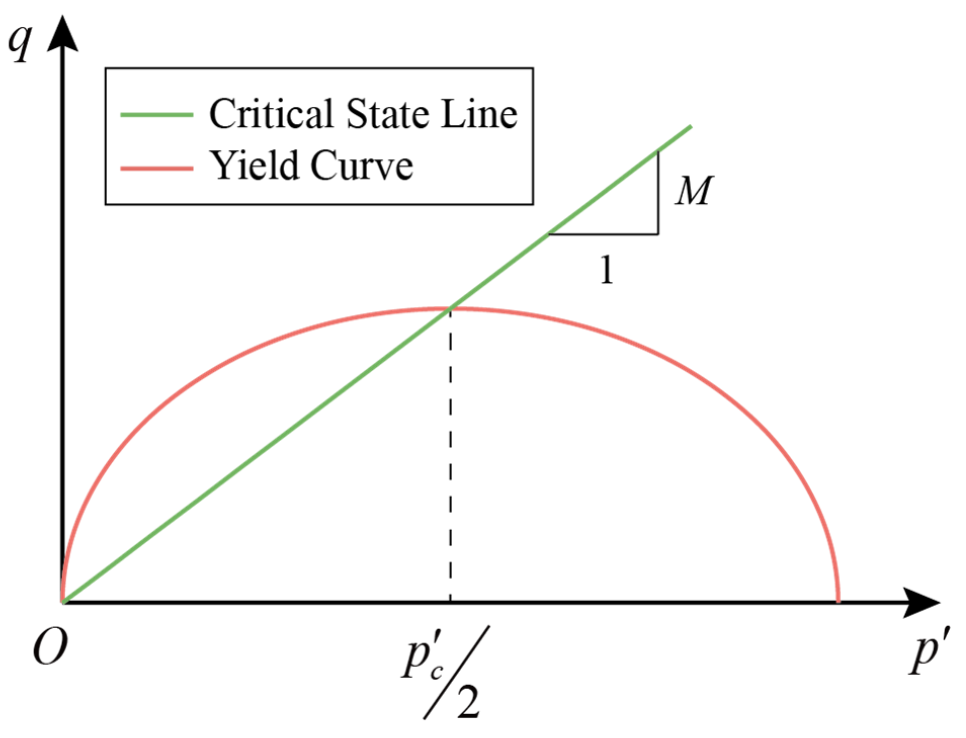
Figure 1. Yield surface of the modified Cam-clay model in the p′–q plane.
Water 16 01375 g001
Figure 2. The diagram of the BP neural network model with one hidden layer.
Water 16 01375 g002
Figure 3. The comprehensive flowchart of the entire research process.
Water 16 01375 g003
Figure 4. The diagram of the foundation pit excavation.
Water 16 01375 g004
Figure 5. The finite element mesh of the system for numerical calculations.
Water 16 01375 g005
Figure 6. The temperature variation during the calculation period.
Water 16 01375 g006
Figure 7. Characteristic points on the floor and main structure of the lock head.
Water 16 01375 g007
Figure 8. Settlement variations at characteristic points on the center and boundary of the foundation surface (2nd–10th are step numbers listed in Table 1).
Water 16 01375 g008
Figure 9. Differences of settlements between center points and boundary points of the floor’s bottom surface.
Water 16 01375 g009
Figure 10. Variations in maximum principal stress at characteristic points on the top surface of the floor.
Water 16 01375 g010
Figure 11. Variations in maximum principal stress at characteristic points in water corridor and hollow box sections.
Water 16 01375 g011
Figure 12. Varying foundation settlement of all samples.
Water 16 01375 g012
Figure 13. Varying max principal stresses of all samples.
Water 16 01375 g013
Table 1. Construction processes of the ship lock head project.
No.Step NameDuration (Days)
1stCasting central floors8
2ndCasting side floors8
3rdDismantling formworks of the floor34
4thBackfilling the first soil layer110
5thCasting water corridor section10
6thDismantling formworks of water corridor section25
7thBackfilling the second soil layer40
8thCasting hollow box section10
9thDismantling formworks of hollow box section55
10thBackfilling the third soil layer77
Table 2. Thermal parameters of concrete and soil.
Materialk
kJ/(m∙d∙°C)
c
kJ/(kg∙°C)
β
kJ/(m2∙d∙°C)
Concrete200.1450.984413 with formworks
1360 without formworks
Subsoil and backfilled soil100.631.005500
Table 3. MCC model parameters of each subsoil layer.
No. λ κ M
10.08360.007061.351
20.08200.006971.052
30.03410.004541.063
40.16610.011260.993
50.13810.009830.852
60.06710.006221.102
70.09190.007481.067
80.11170.008480.864
90.08530.007140.933
Table 4. Other calculation parameters of each subsoil layer.
No. K 0 p c 0 OCR c u
kPa
k s
m/d
ρ
kg/m3
11.312217.6677.065.9250.51880
20.962191.3614.047.4360.0031900
30.594158.6892.040.8150.0861870
40.664183.4661.545.9180.7761900
50.587247.8821.353.0090.0032010
60.452243.2341.167.7860.0031880
70.459287.4981.077.9750.7761900
80.483409.2401.089.0430.0031980
90.450450.5871.0105.7680.0031890
Table 5. Four orthogonally designed samples with different parameter levels.
No.E and Cλ and κ k s
Sample 10.90.90.9
Sample 20.91.11.1
Sample 31.10.91.1
Sample 41.11.10.9
Table 6. Maximum results at characteristic points.
No.D1 (mm)D4 (mm)S1 (MPa)S4 (MPa)
Sample 1274.456262.8782.803152.42602
Sample 2338.13325.0972.826192.54617
Sample 3289.682278.1443.192822.55406
Sample 4321.78309.1593.177072.58789
Table 7. Results of the sensitivity analysis based on Garson’s algorithm.
ParameterS-D1S-D4 σ m a x -S1 σ m a x -S4
E0.24000.24710.27700.2121
C0.17270.19130.24130.2594
λ0.21110.19840.15370.1669
κ0.20030.19500.17070.1956
k s 0.17590.16280.15740.1661
Note: The full names of S-D1, S-D4, σmax-S1, and σmax-S4 are settlement at D1 point, settlement at D4 point, maximum principal stress at S1 point, and maximum principal stress at S4 point, respectively. The meanings of these abbreviations in Table 8 align with this table.
Table 8. Results of the sensitivity analysis based on the partial derivative algorithm.
ParameterS-D1S-D4 σ m a x -S1 σ m a x -S4
E−0.4030−0.43121.05860.7369
C−0.0432−0.0495−0.9146−0.9591
λ1.27971.2568−0.15000.7506
κ1.12431.11750.06640.8368
k s 0.91640.90360.01330.4991
Disclaimer/Publisher’s Note: The statements, opinions and data contained in all publications are solely those of the individual author(s) and contributor(s) and not of MDPI and/or the editor(s). MDPI and/or the editor(s) disclaim responsibility for any injury to people or property resulting from any ideas, methods, instructions or products referred to in the content.