Article

Study on the Seepage Mechanism of Gaskets at the Joints of Shield Segments Based on Coupled Euler-Lagrangian Method

1
College of Geosciences and Engineering, North China University of Water Resources and Electric Power, Zhengzhou 450046, China
2
Disaster Prevention and Mitigation for Urban Underground Transportation Engineering, Henan Provincial Transportation Industry Technology Innovation Center, Zhengzhou 450046, China
3
China Academy of Transportation Sciences, Beijing 100029, China
*
Author to whom correspondence should be addressed.
Water 2024, 16(12), 1661; https://doi.org/10.3390/w16121661
Submission received: 22 March 2024 / Revised: 28 April 2024 / Accepted: 29 April 2024 / Published: 11 June 2024

Abstract

:
In the construction and operation stage of urban shield tunnels, joint leakage of shield is always an urgent problem to be solved. In order to further explore the waterproof performance of elastic rubber gaskets at segment joints, the finite element software ABAQUS (2022) was used to establish a fluid-solid coupling calculation model. The dynamic simulation of the leakage process at the segment joints under water pressure revealed the whole process of leakage at the segment joints and the instant water pressure value when the waterproof system failed. The results show that during the whole process from segment assembly to joint leakage, the elastic rubber gasket has experienced four key stages: gasket compression, confined water pushing, water wedge and final leakage. When the opening amount of the gasket is 6 mm and 10 mm, the contact stress between the gasket shows a “W” symmetrical distribution of high at both ends and low in the middle, and the peak of the contact stress at both ends of the interface is about twice as much as that in the middle. The waterproof threshold of the gasket is closely related to the opening amount of the gasket, and the waterproof threshold has the same trend with the initial contact stress between the gaskets.

1. Introduction

With the acceleration of urbanization and the advancement of mechanized construction, shield tunneling has been widely applied in the construction of urban transportation networks due to its advantages of efficiency, safety, and suitability for various geological conditions [1]. In China, most urban subways are built in strata below the groundwater level. During the construction and operation stages of shield tunnels, leakage of water remains a persistent issue. Currently, the method to prevent leakage at the joints of shield tunnel segments involves filling the segment grooves with elastic rubber seal gaskets, such as Ethylene Propylene Diene Monomer (EPDM) [2]. EPDM, known for its excellent oxidation resistance, corrosion resistance, low cost, and stable performance, has been widely utilized in engineering applications [3].
Research on the waterproof mechanism of seal gaskets at the joints of shield tunnel segments has mainly focused on the critical issue of seal gasket waterproof failure. These studies typically involve finite element software simulations of static waterproof failure of gaskets or reverse analysis of results using gasket waterproof test devices. Research on waterproof tests of sealing gaskets at shield tunnel segment joints can be traced back to Professor Girnau of Germany in the 1970s [4]. Subsequently, Paul [5] discovered through waterproof tests that leakage was more likely to occur between elastic sealing gaskets and metal molds. With the deepening of research, Liu et al. [6] have proposed an innovative seepage model test system for undersea tunnels. The system not only effectively simulates uneven settlement and segment joint deformation in the model but also accurately displays gasket stress relaxation, deterioration of seawater erosion, and leakage phenomena. Based on the newly developed test device, Zhang et al. [7] found that there is a close correlation between the mechanical properties of the gasket and the waterproof performance, and the deterioration of the waterproof performance of the gasket is usually due to the offset of the joint. Zhao et al. [8] conducted waterproof performance tests on one-shaped and T-shaped seams of segment joints and proposed a design method for elastic rubber sealing gaskets at large-diameter shield tunnel segment joints based on the research results. Shalabi et al. [9] studied the variation in waterproof performance of shield tunnel segment joints under dynamic and static loads through watertightness tests at segment joints. Ding et al. [10] analyzed the waterproof performance of the double-channel elastic rubber gasket through the waterproof test device of the gasket and found that the waterproof ability of the double-channel gasket decreased with the increase of the opening amount of the joint, and the failure mode depended on the layout of the double-channel gasket.
Although experiments allow for the direct observation of the maximum water pressure of elastic rubber sealing gaskets under different displacements and openings, understanding their deformation characteristics and the distribution of contact stresses under water pressure is challenging. In contrast, numerical methods can effectively compensate for this limitation, providing us with a more comprehensive analysis. Many scholars are dedicated to establishing ontological relationships or models for research. For example, the numerical simulation sequence method provided by Karpenko et al. [11] helps engineers effectively determine the dynamic characteristics and behavior of vehicle tires during the design phase. As the research progresses, a consensus is gradually forming that the Mooney-Rivlin and Yeoh models can effectively simulate the mechanical behavior of shield tunnel segment joint sealing gaskets [12,13,14,15,16]. Zhang et al. [17] revealed the dynamic process of waterproof failure of sealing gaskets and analyzed the interaction between the sealing gaskets and water after waterproof failure. Sun [18] combined with Hangzhou Metro Line 1 analyzed the waterproof performance, contact stress distribution, and waterproof failure modes of elastic rubber sealing gaskets under different displacements using a numerical model and proposed a method for evaluating waterproof performance. Zhang et al. [19] completed the optimization of rubber hardness parameters in the waterproof design of the gasket by studying the contact pressure of the joint gasket. Xie et al. [20] proposed a novel analytical model based on multiscale contact and percolation theories, in which the obtained percolation pressure and interfacial separation can be utilized to derive the critical water leakage pressure and leakage rate.
So far, most traditional numerical simulation methods for dealing with joint leakage problems are based on static loading conditions, simply replacing the water acting on the sealing gasket with static loads. However, this method cannot accurately reflect the dynamic evolutionary characteristics of hydraulic processes. Based on theoretical and experimental studies of hydrodynamic processes, Karpenko et al. [21] analyzed the influence of hydrodynamic processes on the turbulent development of fluid passing through a pipe-fitting system. In fact, the seepage of water through the joints of tunnel segments constitutes a fluid-structure coupling process, where the interaction between the fluid and the elastic rubber sealing gasket dynamically evolves with the progress of seepage. In order to explore and reveal the dynamic seepage process of pipe joints and to understand in more detail the factors affecting the waterproofing ability of pipe joints, a comprehensive simulation model of the seepage process of pipe joints based on the Euler-Lagrange coupling (CEL) model was established using ABAQUS software.

2. Project Overview

The Zhengzhou Metro Line 5 is a subway line that runs through Zhengzhou City in Henan Province, connecting Zhengdong New District, Jinshui District, Zhongyuan District, Erqi District, and Guancheng District. It forms an underground loop line that covers most of the planned routes in the Zhengzhou Metro system. The line is 40.4 km long and has 32 stations, making it the fourth operational subway line in Zhengzhou. It began operating on 20 May 2019. The tunnel location map is shown in Figure 1. This study focuses on the Yuansha section of Zhengzhou Metro Line 5. According to regional hydrogeological data, the groundwater in this tunnel section is primarily composed of pore water in the loose layers of the Quaternary System. The aquifer lithology mainly consists of cohesive silt, powdery clay, and fine sand. The initial depth of the groundwater table ranges from 19.70 to 25.80 m, while the stable depth ranges from 19.20 to 25.30 m, with a fluctuation of 1.0 to 2.0 m. Groundwater recharge mainly comes from atmospheric precipitation and underground runoff. Surface water runoff is minimal due to surface hardening, so underground runoff replenishment is dominant. According to regional geological data, the direction of underground runoff is from west to east, southwest to northeast. Based on meteorological data for Zhengzhou, the recharge period, or high-water season, occurs from July to September each year, while the low-water period, or dry season, extends from December to March of the following year.
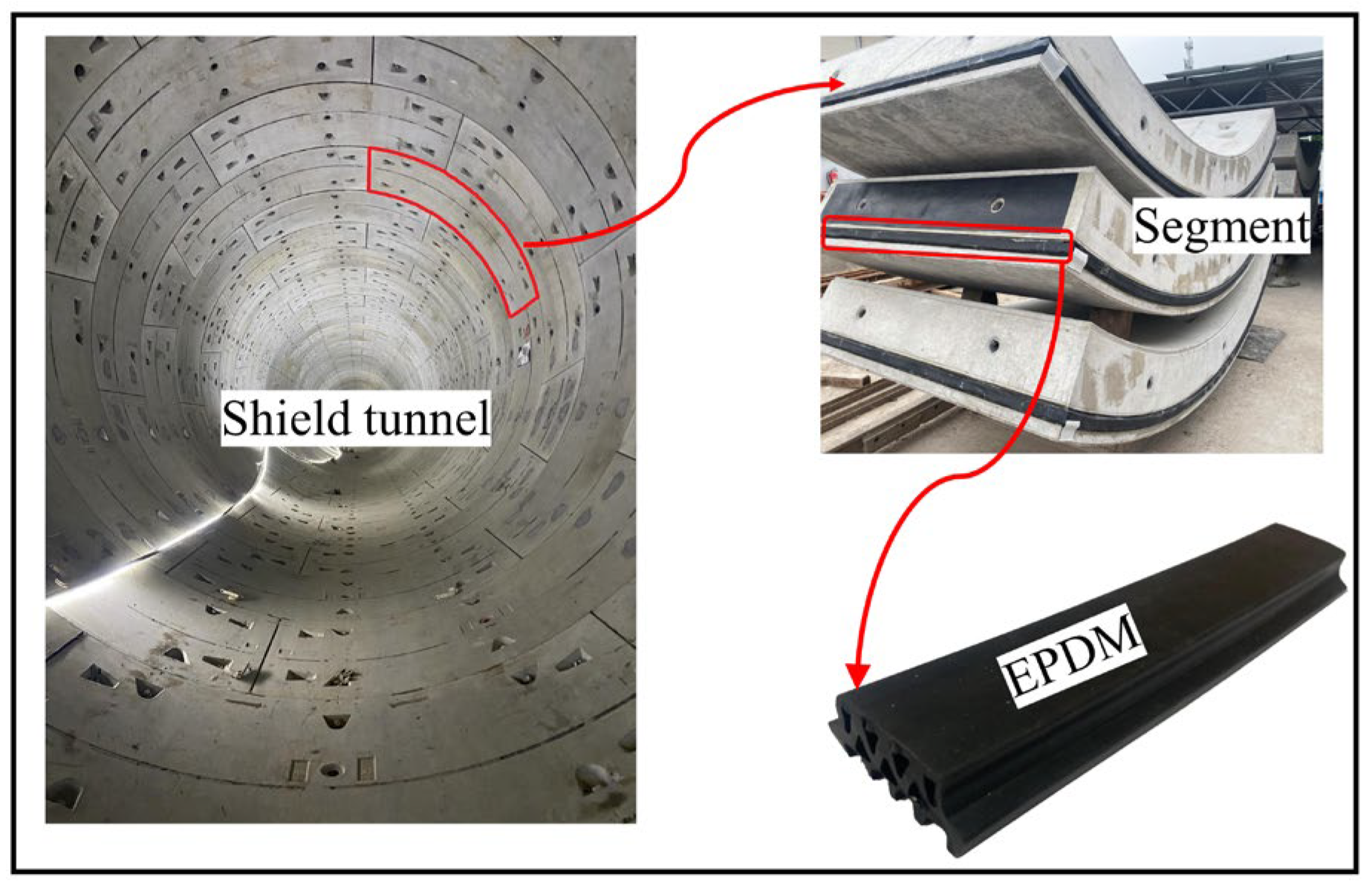
The shield tunnel lining for Zhengzhou Metro Line 5 has a cross-section with specific measurements. The inner diameter of the lining is 5500 mm, the outer diameter is 6200 mm, and the thickness is 350 mm. To ensure a tight seal between the tunnel segments, ethylene propylene diene monomer (EPDM) elastic rubber seals are used, as illustrated in Figure 2. Figure 3a provides a visual representation of the cross-section diagram of the shield tunnel, while Figure 3b displays the precise dimensions of the sealing gasket.
According to the waterproof design of the tunnel section, in order to ensure the width of the sealing gasket on both sides of the joint, it is required that the elastic sealing gasket can withstand a water pressure of 0.7 MPa under the most unfavorable conditions (and greater than 3 times the burial depth). Therefore, a water pressure of 0.7 MPa is chosen for the design in this document.
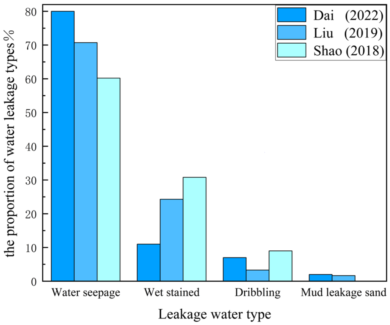
Based on the differences in the seepage flow rate of water leakage diseases in shield tunnels, leakage water types are typically categorized as dampness, seepage, dripping, and slurry leakage [22]. The types and definitions of leakage water in shield tunnels are presented in Table 1 below. In-depth research into the process of shield tunnel leakage water diseases, through systematic collection of the relevant literature data [23,24,25], and detailed statistical analysis, reveals the main types of leakage water diseases, as illustrated in Figure 4.
Based on the analysis of the investigation results on the types of leakage water in shield tunnels, it can be observed that among the four types of leakage water diseases, seepage is the most common, accounting for as much as 60% to 80%. Following seepage are dampness, dripping, and slurry leakage diseases. Although slurry leakage occurs less frequently, it poses significant hazards to tunnel safety. When the leakage volume is considerable, it can easily entrain soil particles and sediments behind the tunnel lining, leading to severe soil erosion in the surrounding environment. In severe cases, this can result in voids behind the tunnel lining, causing stress concentration in the lining structure and thus posing a threat to the overall safety of the tunnel.
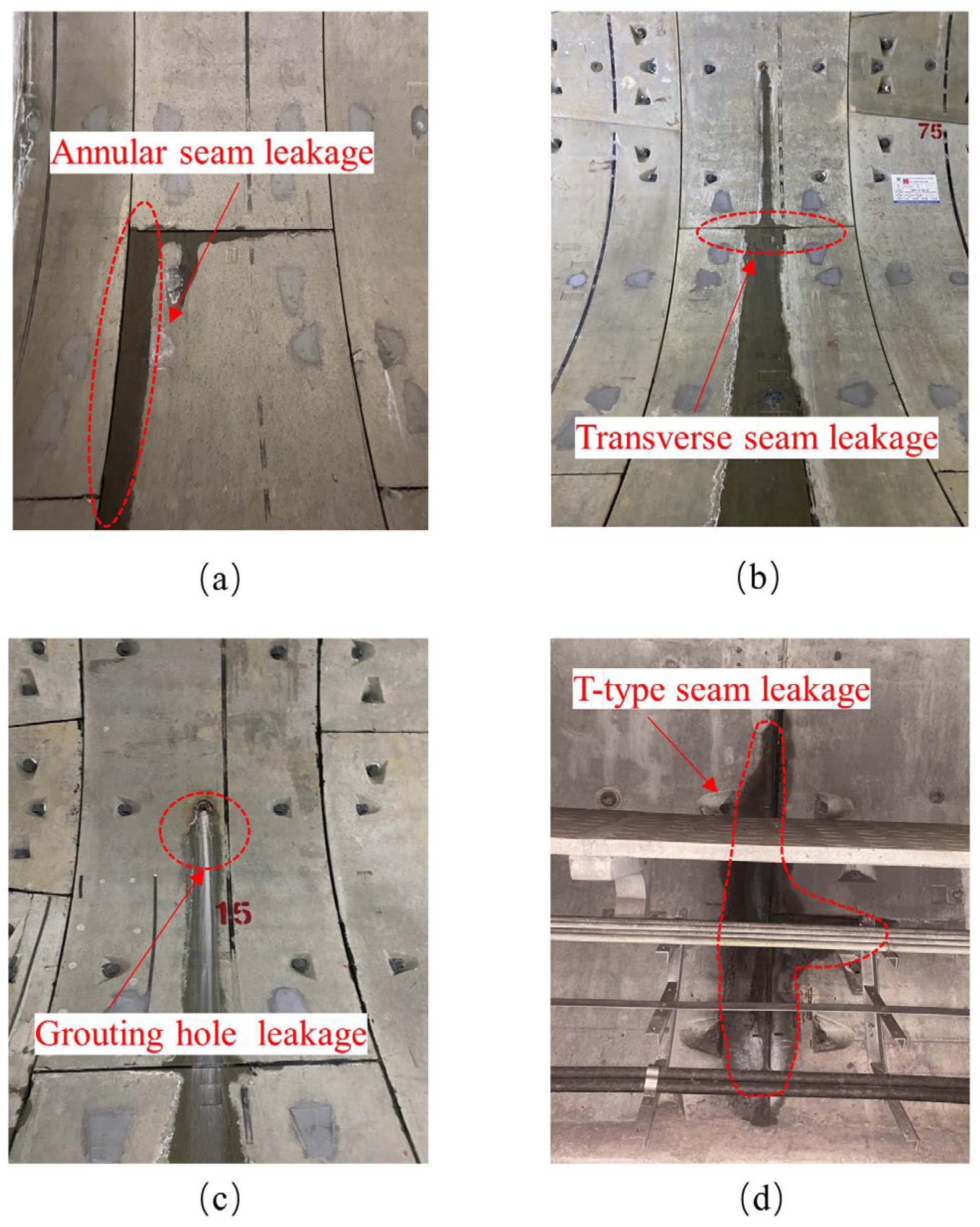
The common leakage positions in shield tunnels mainly include annular seam leakage, transverse seam leakage, grouting hole leakage, T-type leakage, and so on, as shown in Figure 5. Through visual inspection, the leakage situation in the shield tunnel section is surveyed on-site, as presented in Table 2.
The statistical results show that the most common location for water leakage is at the T-joint, accounting for 50%. The combined percentage of ring joint and transverse joint leakage is 35%, followed by bolt holes and pre-grouting holes. It is noteworthy that the comprehensive percentage of leakage at joints is 85%, indicating that the main location of water leakage in shield tunnels occurs at the joints.

3. CEL Fluid-Solid Coupling and Numerical Modeling

3.1. CEL Fluid-Sructure Coupling

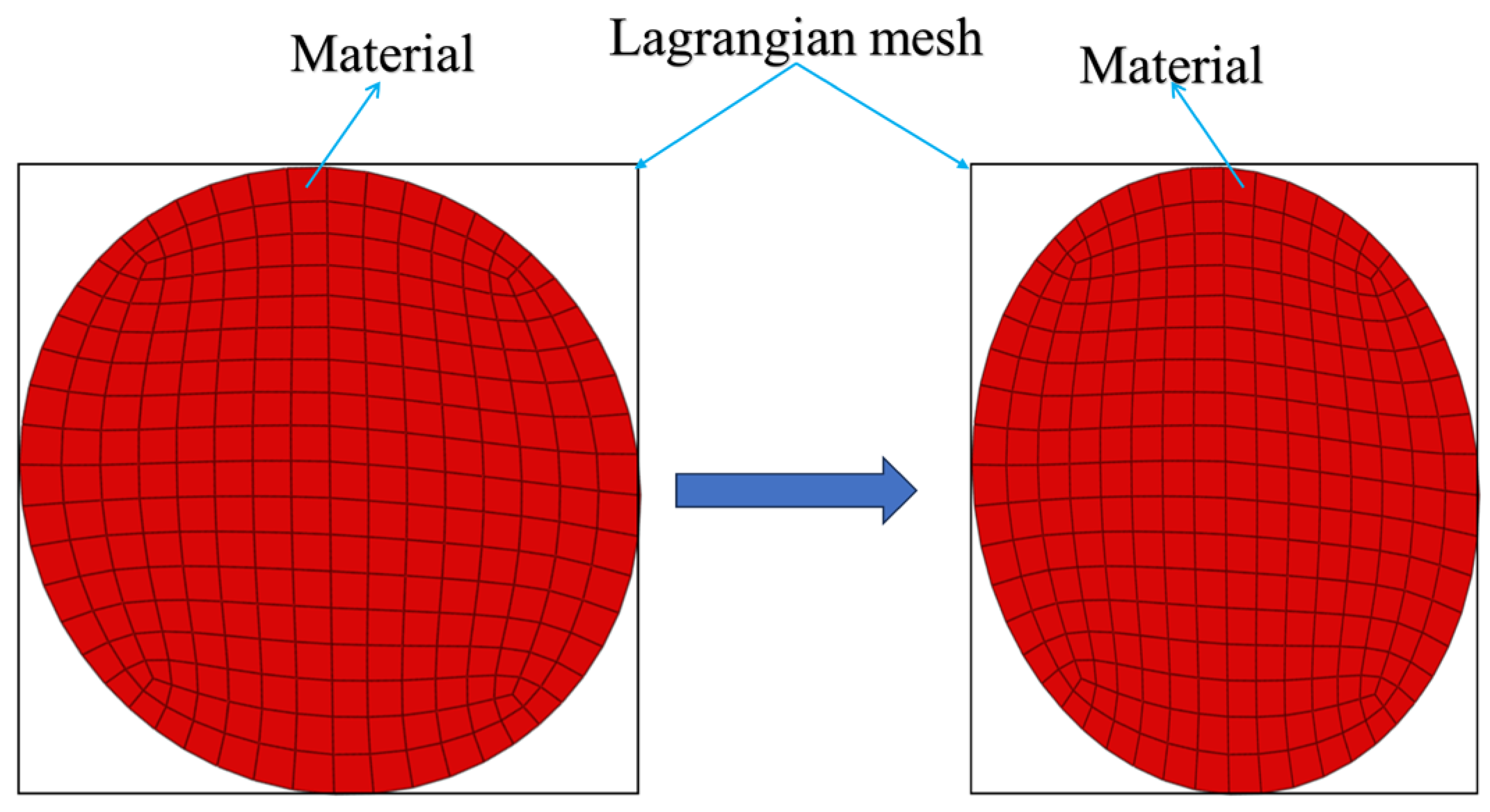
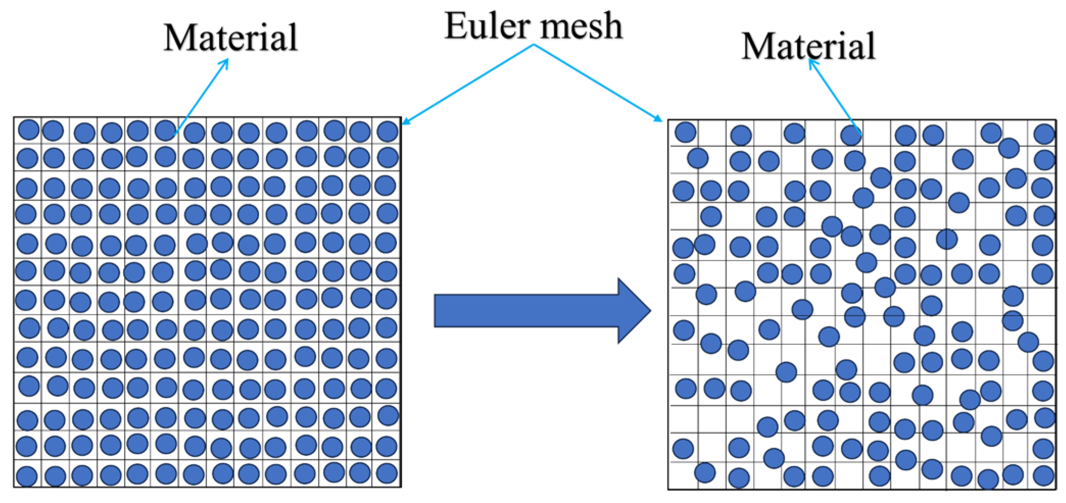
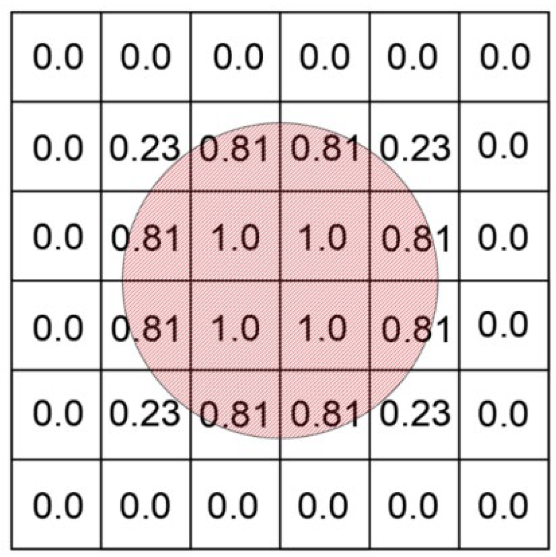
In ABAQUS, Eulerian materials interact with Lagrangian elements through Euler-Lagrangian contact, and this type of contact analysis is commonly referred to as Coupled Eulerian-Lagrangian analysis [26]. This method has significant advantages in handling large deformations of solid materials and supporting adaptive mesh refinement. Generally, in the Lagrangian mesh, the displacement of deformable bodies is a function of material coordinates and time, where nodes are closely connected to the material and elements deform correspondingly with the material. A notable feature of the Lagrangian mesh is that it is always filled 100% with a single material, ensuring consistency between the material boundary and the element boundary, as shown in Figure 6. In contrast, in the Eulerian mesh, the displacement of deformable bodies is a function of spatial coordinates and time. The finite element nodes are spatial nodes, fixed in space, and the material flows through these undeformed elements [27]. Since Eulerian elements may not be completely filled with material, many elements can be partially or completely empty, thus the material boundary is redefined at each time increment step, as illustrated in Figure 7.
In the CEL method, Eulerian materials can penetrate the mesh with complete separation between material and mesh. The fundamental continuity equations governing the motion of rigid bodies and deformable bodies are [28].
D p D t + p × v = p t + v × p + p × v
The equations of motion:
p × D v D t = × σ + p b
where:
D v D t = v t + v × v  
The energy equation is:
p × D E D t = σ × ε ˙ + p Q ˙  
ε ˙ = 1 2 v + v T  
In the formula: D / D t   is the time derivative of material; / t is the space-time derivative; p is the material density; is a gradient operator; v is the material velocity; σ is the Cauchy stress tensor; b is physical strength; E is the unit volume internal energy; ε ˙ is the strain tensor rate; Q ˙ is the energy consumption rate per unit volume. v is the velocity gradient tensor; v T is the transpose of the velocity gradient tensor.
In the CEL method, the deformation of Eulerian materials is achieved through a fluid volume approach [29]. This method determines the material flow trajectory in the mesh by computing the Eulerian volume fraction (EVF) in each element. When an element is completely filled with material, its EVF = 1; conversely, when an element contains no material, its EVF = 0. It is worth noting that when the EVF of all materials in an element is less than 1, the remaining portion of the element is automatically occupied by “empty” material, which has neither mass nor strength.
In ABAQUS, the initial geometry containing Eulerian materials can be defined as the initial material pre-defined field. Subsequently, Eulerian materials can be allocated to the initial Eulerian geometry portions based on the Eulerian volume fraction. For cases with more complex geometric shapes, direct use of discrete fields for definition is possible, as shown in Figure 8, whereas for simpler geometric shapes, uniform fields can be used for definition.
In ABAQUS, the CEL method requires explicit dynamic analysis to be implemented. To ensure the numerical stability of the explicit algorithm, it is necessary that the time increment used in the computational settings be smaller than the stable calculation of the central difference operator, namely:
t < t m i n = L e c d  
where L e represents the characteristic element size; c d denotes the speed of the expansion wave [28].

3.2. Model Construction

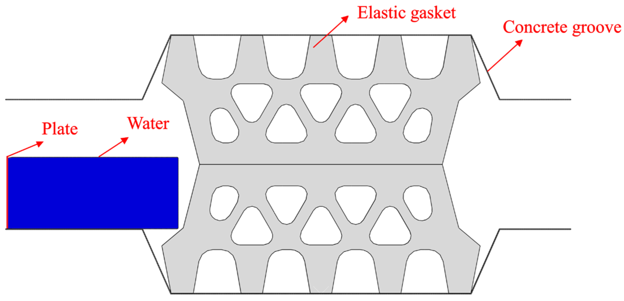
The fluid–solid coupling model at the joints of shield tunnel segments constructed through Eulerian-Lagrangian analysis method mainly includes elastic rubber sealing gaskets, concrete grooves, water, and the plates driving the flow of water, as shown in Figure 9.

3.2.1. Constitutive Relationship of Materials and Parameter Settings

Considering that the stiffness of the elastic rubber sealing gasket is much smaller than that of concrete, to simplify the calculation, the concrete grooves are treated as rigid bodies. Reference points are set on the concrete grooves to apply displacement loads [30]. Rubber materials are typically treated as isotropic, incompressible hyperelastic materials. For this calculation, the simulation adopts the Mooney-Rivlin model for incompressible rubber material [31]. The constitutive model needs to determine two parameters C 10 and C 01 , and the strain energy function is as follows:
U = C 10 I 1 3 + C 01 I 2 3  
In the formula, C 10 and C 01 are Rivlin coefficients, which are positive constants.
Typically, the Mooney–Rivlin constants C 10 and C 01 are obtained by uniaxial tensile or compressive tests. The relationship between rubber hardness (HA) and Mooney–Rivlin constant is shown in Table 3.
According to the “ABAQUS Analysis User’s Manual”, simulating pressurized water using a fluid mechanics material model typically involves fitting Hugoniot data with the following equation:
P H = ρ 0 c 0 2 η 1 s η 2  
where P H is Hugoniot pressure, kPa; c 0 and s define the linear relationship between the linear impact velocity U s and the particle velocity U p , as follows:
U s = c 0 + s U p  
Using the above assumptions, the linear U s U p Hugoniot form is written as:
p = ρ 0 c 0 2 η 1 s η 2 1 Γ 0 η 2 + Γ 0 ρ 0 E m
In the formula, Γ 0 is the material constant; E m is the internal energy per unit mass, kN·m; ρ 0 is fluid density, kg/mm3; η is the nominal volume compressive strain, and ρ 0 c 0 2 η is equivalent to the elastic modulus when the nominal strain is small.
The initial state parameters of the fluid material are shown in Table 4.

3.2.2. Setting of Eulerian Domain and Initial Material Assignment

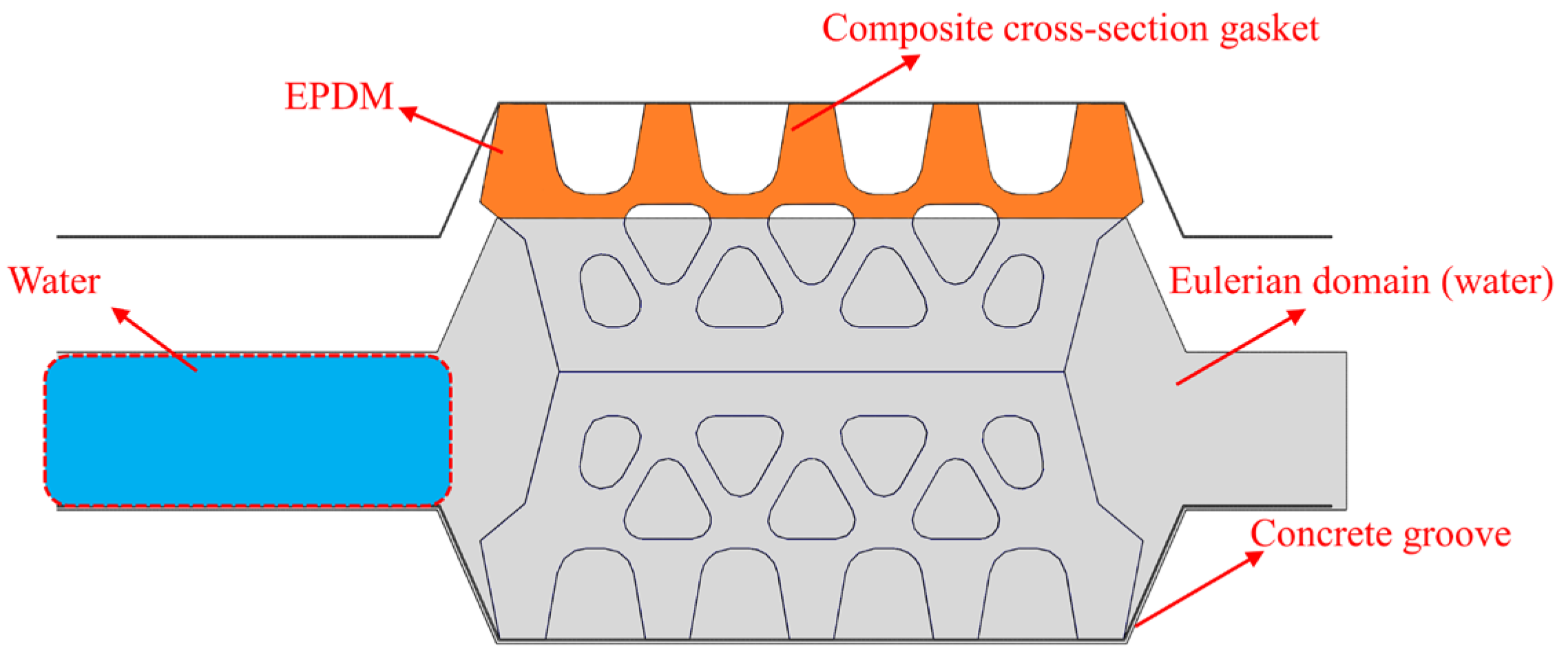
When simulating fluid materials, Eulerian mesh is commonly used, which primarily consists of Eulerian and reference bodies. The Eulerian body provides space for fluid flow, and it is essential to determine the flow range of the fluid during modeling. Once the Eulerian body is established, volume fraction tools are utilized to assign regions and materials to the reference body. The regions of the Eulerian and reference bodies are illustrated in Figure 10.

3.2.3. Contact Relations and Boundary Conditions

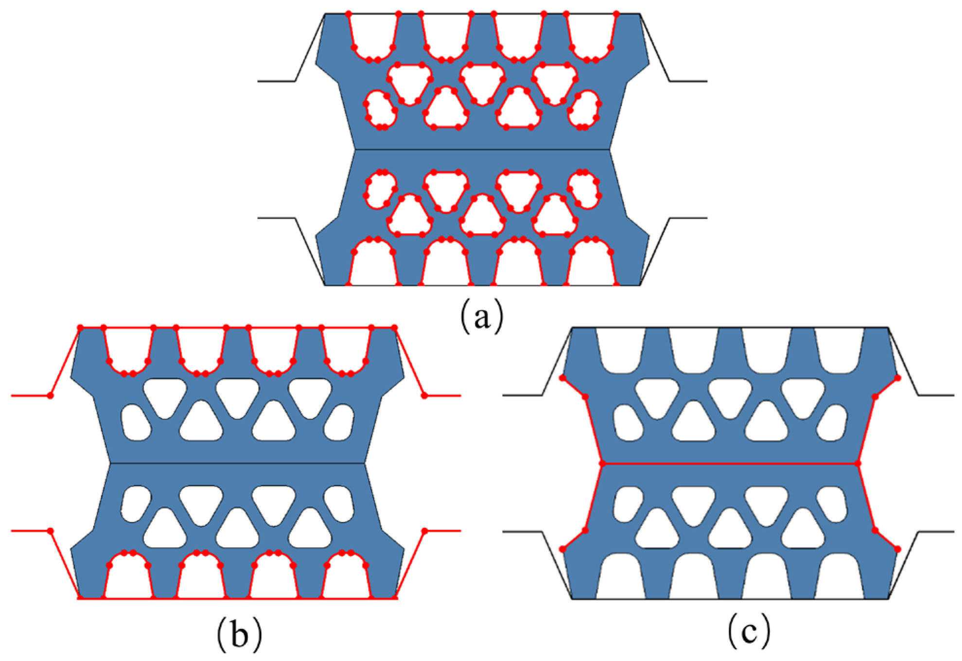
After assembling the model, it is necessary to set the contact types between the Eulerian and Lagrangian bodies. In order to achieve the coupling between solids and fluids, the contact type between the Eulerian and Lagrangian bodies is set to a general contact based on the “penalty” contact method [32]. Considering that the elastic sealing gasket has multiple holes and various cross-sectional shapes, it is crucial to reasonably set the contact relationship between the gasket itself and between the gasket and the concrete grooves. During the simulation, self-contact is applied to the outer surface of the gasket and between internal holes, as shown in Figure 11a. The contact attributes for the normal direction are set to hard contact, while the tangential direction is set to penalty mode, with a contact friction coefficient of 0.3. Surface contact is employed between the gasket and between the gasket and the concrete grooves, as shown in Figure 11b,c, with a contact friction coefficient set to 0.5.
The ABAQUS/Explicit calculation model is adopted, and the model calculation mainly consists of two analysis steps: first, the compression process of the elastic rubber sealing gasket, and second, the water pressure loading process. During the compression process of the elastic rubber sealing gasket, a quasi-static approach is followed to simulate the compression process of the elastic rubber sealing gasket with a very small loading velocity. In this process, the degrees of freedom of the lower groove are fully constrained, while the upper groove is subjected to loading, compressing the sealing gasket to a predetermined gap. It is important to note that during the compression process of the elastic rubber sealing gasket, the longitudinal motion of the sealing gasket needs to be constrained. Upon completion of the compression process, the model enters the water pressure loading phase, where displacement loads are applied to the pressure plate to push the Eulerian fluid, squeezing the elastic rubber sealing gasket, thus simulating the leakage process of shield tunnel segments. It is essential to note that in this phase, boundary conditions need to be set for the Eulerian domain to prevent Eulerian material from flowing out of the Eulerian domain.

3.3. Model Verification

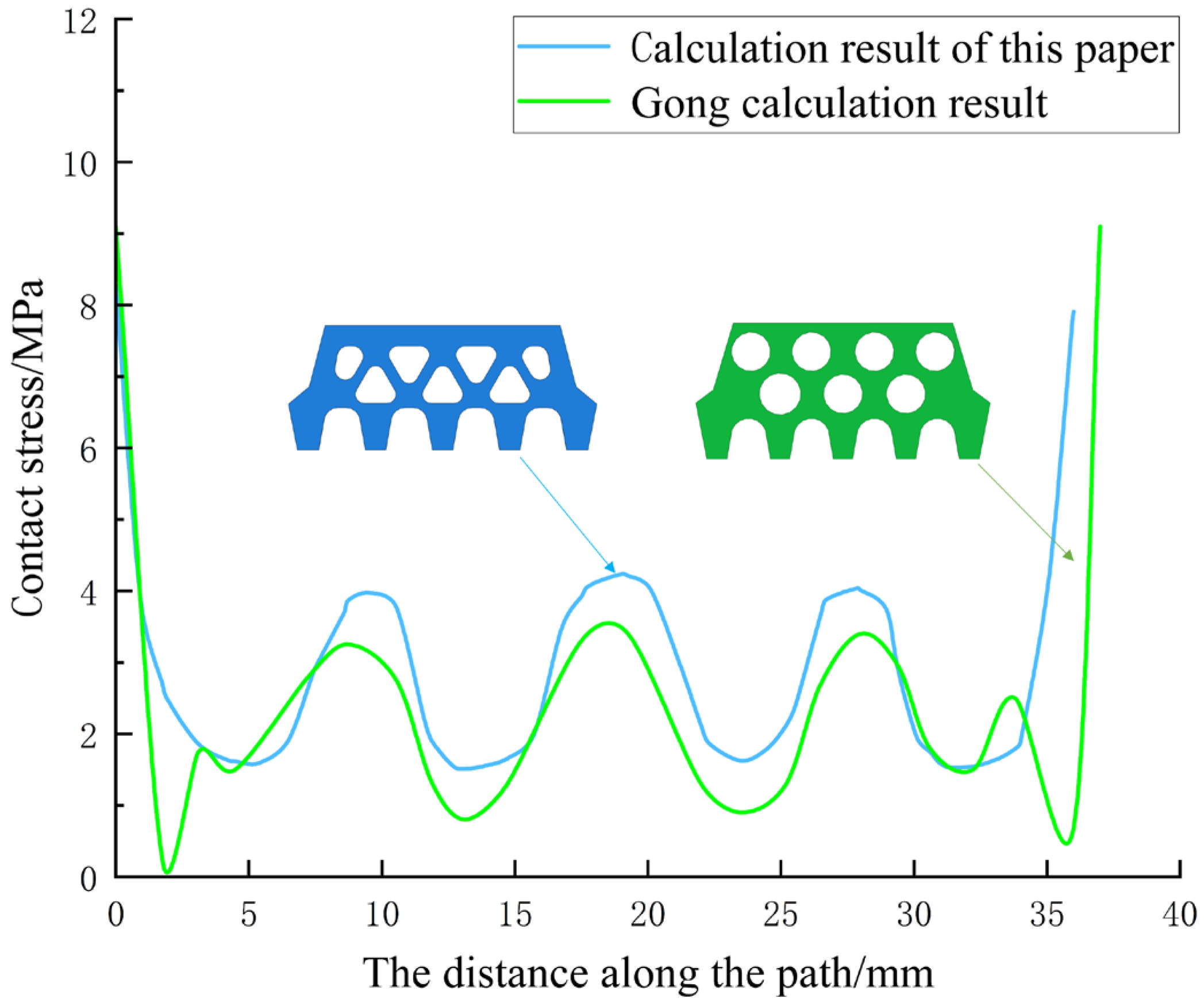
To ensure the accuracy of the subsequent computational analysis, it is necessary to verify the effectiveness of the gasket model constructed in this paper. Previously, Gong et al. [33] used the ABAQUS software to analyze the contact stress of an elastic rubber gasket under compression and obtained the contact stress when the gasket opening is 0 mm. In order to verify the correctness and reliability of the model presented in this paper, the contact stress of this model under the same conditions (i.e., when the opening amount was 0 mm) was compared with the research results of GONG et al. See Figure 12 for the comparison results.
From the comparison of the graphical data, the model established in this paper is in good agreement with the calculated results of GONG et al. in the overall trend. However, there are differences in the specific values, which are mainly due to the difference in the section of the two gaskets and the difference in the design of the holes in the structure, resulting in the numerical difference in the simulation results. Nevertheless, this comparison still validates the rationality and accuracy of the model in this paper to a certain extent, and lays a foundation for further analysis of the elastic gasket under the action of water pressure.

4. Leakage Mechanism of Sealing Gasket at Shield Segment Joint

4.1. Leakage Process

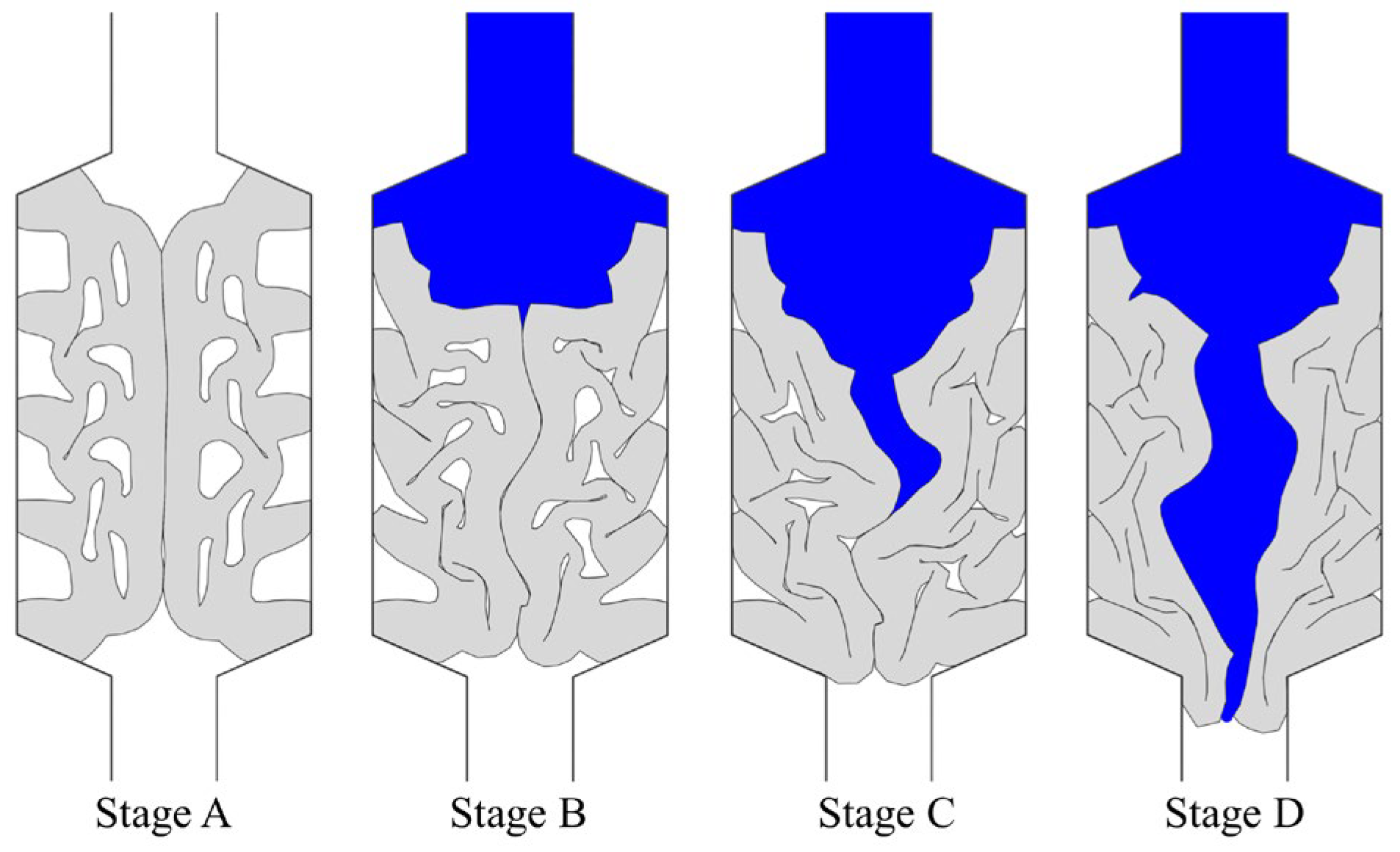
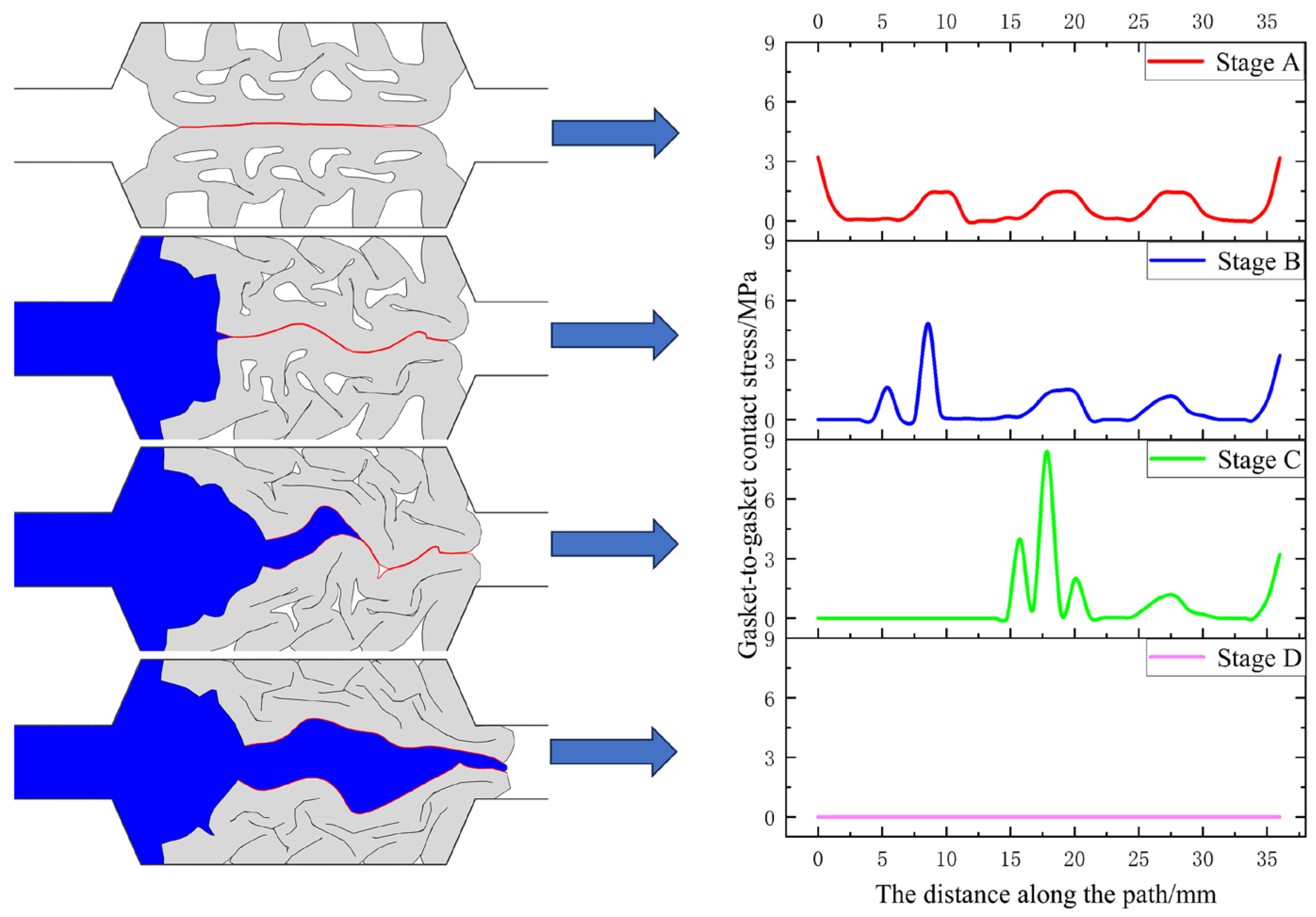
Throughout the entire process, starting from assembling the pipe segments to experiencing leakage at the joints, the elastic rubber sealing gasket undergoes four key stages: gasket compression, pressurized water extrusion, water wedge insertion, and eventual leakage. Under the pressure of the water, the interface between the sealing gaskets is initially separated, creating a gap. As pressurized water is extruded, the gap between the sealing gasket-sealing gasket interface gradually widens until it is breached by the pressurized water, resulting in joint leakage. The leakage at the shield tunnel segment joint can be further divided into the following four stages, as depicted in Figure 13.
Stage A: The compression stage of the sealing gasket. As the concrete segments exert pressure, the elastic rubber sealing gasket gradually deforms to fill the entire cavity of the concrete groove, creating surface contact stresses to resist external water pressure.
Stage B: Pressurized water extrusion stage. The pressure plate squeezes water into the joint between the segments, coming into contact with the outer sealing gasket. At this point, the outer side of the elastic sealing gasket is deformed due to the extrusion, reducing the gaps in the sealing gasket and generating additional contact stresses. The sealing gasket’s resistance to water pressure is further increased. Under the action of water pressure, initial gaps appear between the elastic rubber sealing gasket and the sealing gasket. Water is squeezed into these gaps, marking the beginning of leakage at the joint between the elastic rubber sealing gasket and the sealing gasket.
Stage C: Water wedge insertion stage. Under the external water pressure, water wedges into the sealing gasket, and the flow path between the sealing gaskets gradually develops. At this point, half of the interface between the sealing gaskets separates, and the pressurized water continues to squeeze the remaining gaps in the sealing gasket. The squeezed elastic sealing gasket moves to both sides and tends to deform downward.
Stage D: Final breakthrough stage. As the water pressure increases further, water continues to press against the elastic rubber sealing gasket. At this point, the elastic rubber sealing gasket completely separates, resulting in leakage at the shield tunnel segment joint, leading to failure of the waterproofing system.
The mechanical and deformation behavior of the elastic rubber sealing gasket changes with the magnitude of the gap opening. Generally, as the gap opening decreases, the contact stress of the elastic rubber sealing gasket increases. Under the pressure of the water, the sealing gasket is continuously squeezed, thus forming a flow path along the contact interface of the sealing gasket.
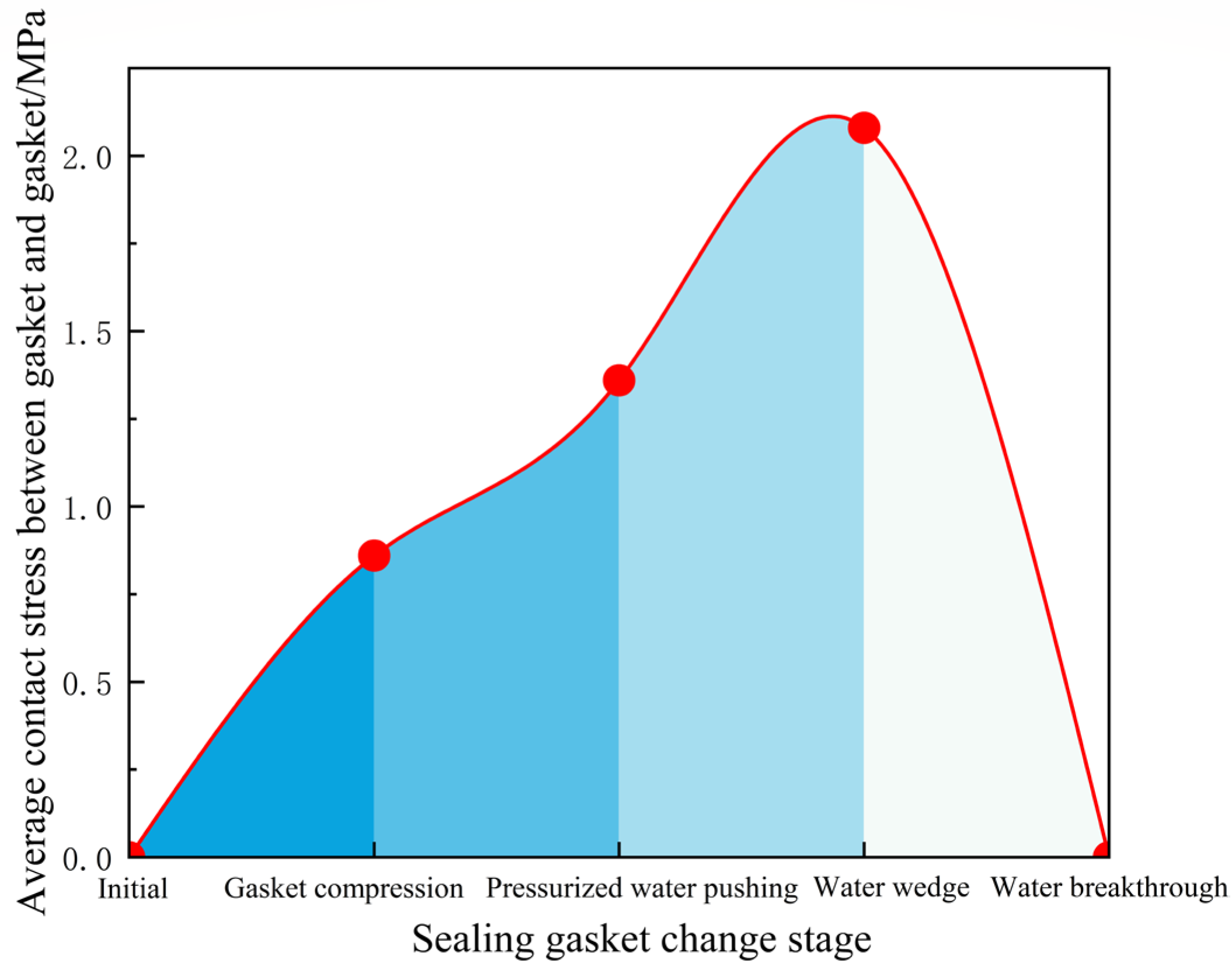
As shown in Figure 14, the average contact stress of the sealing gasket can be observed at different stages. When the gap opening reaches 6 mm after completing the compression, due to the pressurized water extrusion and water wedge insertion, the average contact stress between the sealing gaskets shows a continuous increasing trend. During the pressurized water extrusion stage, the average contact stress between the sealing gaskets increases by approximately 58.1%. When the water starts to wedge in, the average contact stress between the sealing gaskets begins to decline until it reaches 0 after the water breakthrough.

4.2. Seepage Stress Barrier

The permeation stress barrier, which is formed by the initial contact stress, defines the envelope [34]. In the simulation process, pressurized water must overcome this barrier along its flow path in order to permeate. Therefore, the permeation stress barrier plays a crucial role in determining the waterproof performance of the gasket at the joint of the pipe segments. As shown in Figure 15, the distribution of initial contact stress between the sealing gaskets exhibits a “W” symmetrical distribution when the gap opening is 6 mm and 10 mm. This means that the contact stress is higher at the ends and lower in the middle. This phenomenon occurs because there is stress concentration at the ends of the sealing gasket. Furthermore, as the gap opening decreases, the peak contact stress in the middle of the contact surface of the elastic rubber sealing gasket gradually increases. The magnitude of this contact stress is crucial for the waterproof performance of the sealing gasket. Therefore, decreasing the gap opening effectively enhances the waterproof performance of the sealing gasket.

4.3. Dynamic Variation of Interface Stress

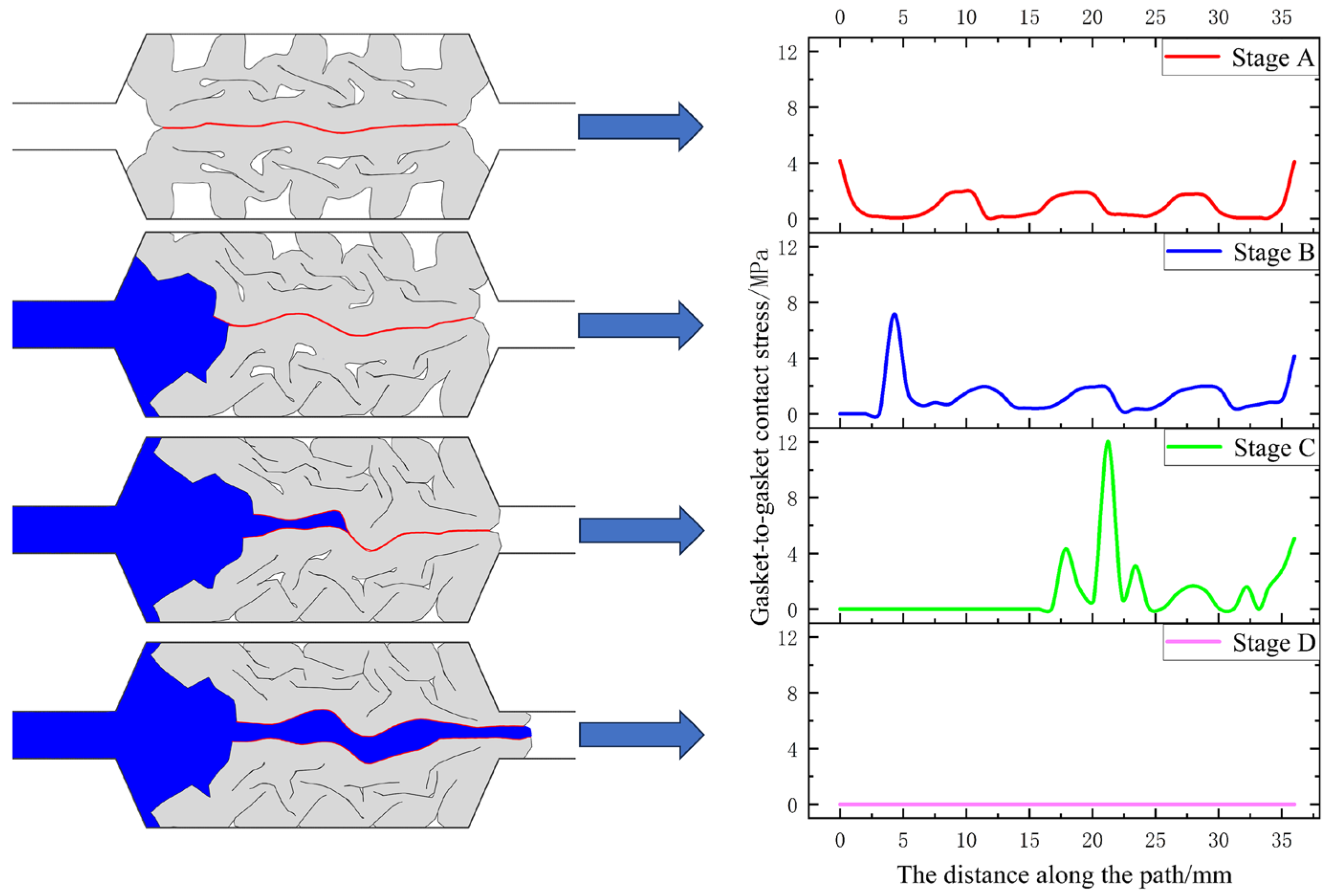
The contact stress between the sealing gaskets at different stages of leakage is demonstrated in Figure 16 and Figure 17. Stage A corresponds to the completion of gasket compression, while Stages B, C, and D represent the pressurized water extrusion, water wedge insertion, and final leakage stages, respectively. To determine the failure of the waterproof system in the shield tunnel segment gasket under water pressure, the criterion is the absence of contact stress between the sealing gaskets. If the contact stress exceeds zero, the waterproof system is deemed effective. Conversely, if the contact stress equals zero, the waterproof system is considered to have failed.
From Figure 16 and Figure 17, it is evident that as the water pressure increases, the region at the interface of the sealing gasket where the contact stress is lower than the water pressure will gradually expand. Consequently, the contact stress at different points on the contact surface will also change accordingly. With a further increase in water pressure, groundwater will infiltrate beyond the point of maximum contact stress, causing the sealing gasket at the highest contact stress point to progressively open up. This results in a gradual loss of waterproofing capability. When the gap opening measures between 6 mm and 10 mm, the trend of contact stress between the sealing gaskets is the same. However, the variation in contact stress between the sealing gaskets is greater when the gap opening is 6 mm compared to 10 mm. Contact stress propagates forward along the flow path in a wave-like manner. Stress breakthrough points between the sealing gaskets occur in areas where the pressurized water is compressed. In areas where the pressurized water has not penetrated the sealing gasket, the overall trend of the contact stress between the sealing gaskets remains consistent. However, when the pressurized water infiltrates the sealing gasket, the contact stress between the sealing gaskets reaches zero, indicating complete separation between them.
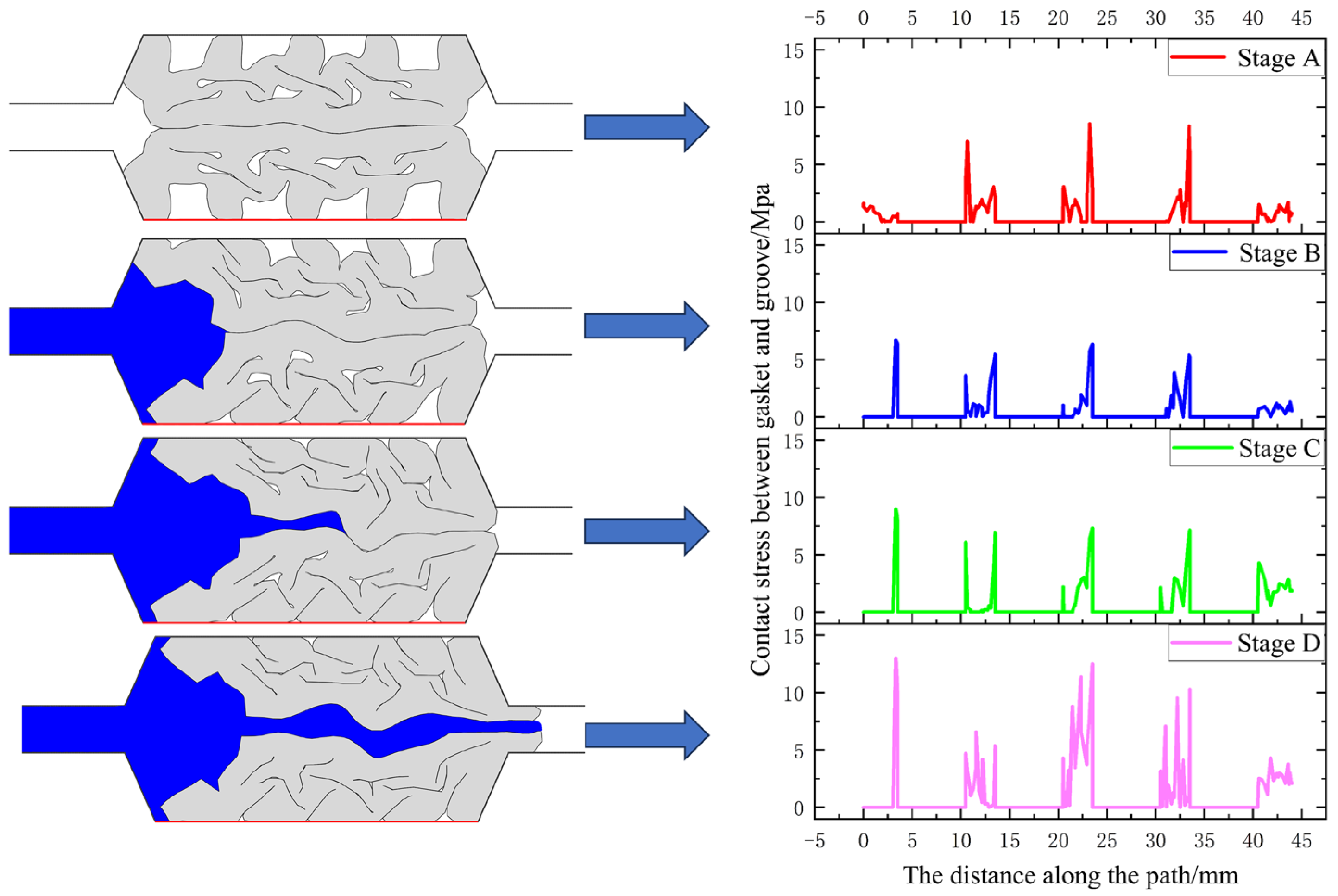
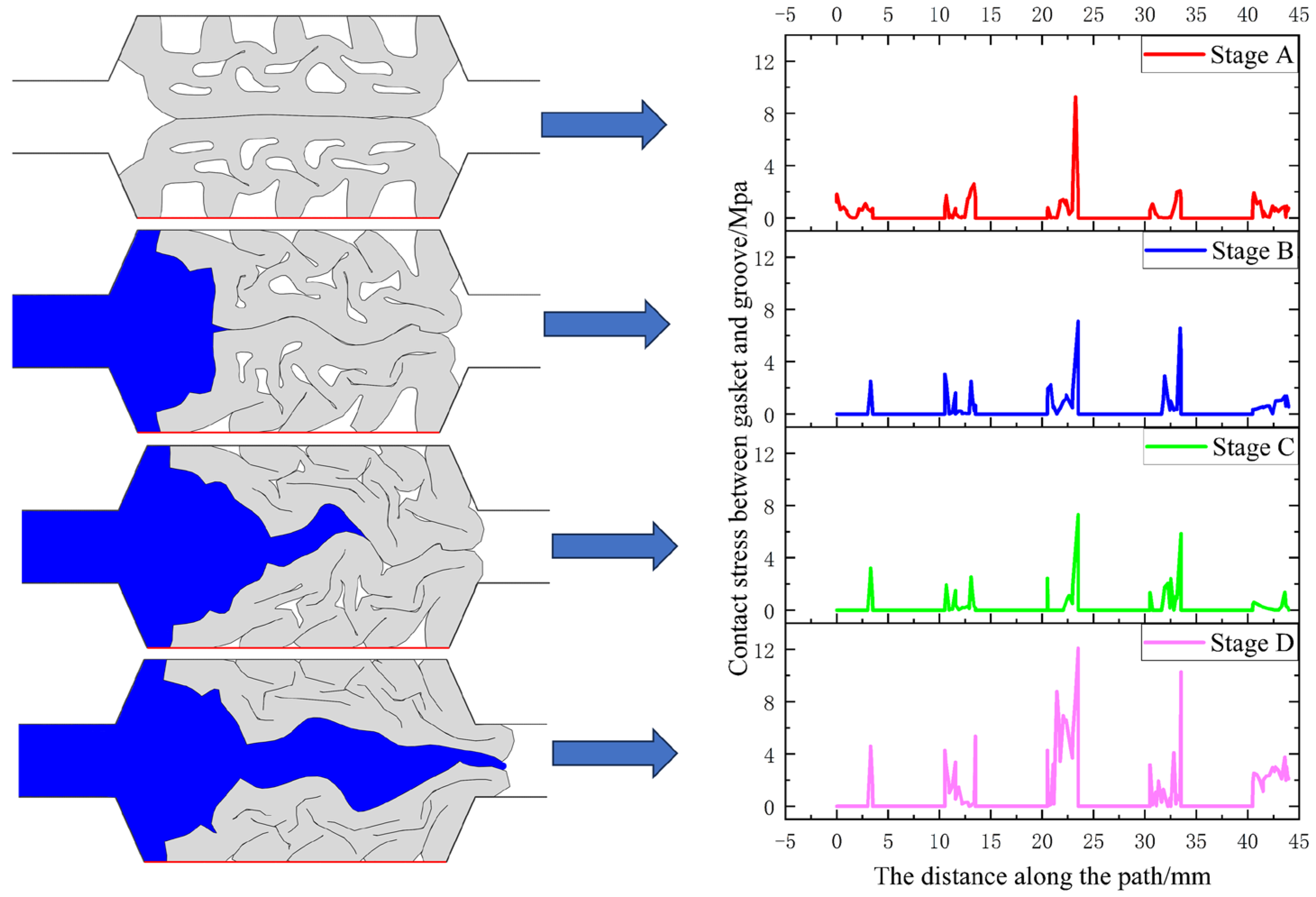
The contact stress between the sealing gasket and the concrete groove during different stages of leakage is shown in Figure 18 and Figure 19. Stage A represents when the gasket compression is completed, while Stages B, C, and D represent the pressurized water extrusion, water wedge insertion, and final leakage stages, respectively. From the figures, it is evident that the contact stress between the sealing gasket and the concrete groove fluctuates intermittently throughout the entire water seepage process. This fluctuation is primarily caused by the irregular compression of unclosed holes on the interface between the sealing gasket and the concrete groove. As the pressurized water enters, influenced by the external water pressure, the peak contact stress gradually increases between the sealing gasket and the concrete groove. When the pressurized water eventually penetrates the sealing gasket, the contact stress between the sealing gasket and the concrete groove reaches its maximum value. Analyzing the distribution of contact stress between the sealing gasket and the concrete groove within the range of 0–5 mm, it is noticeable that the contact stress shifts from gasket compression to external water squeezing and leakage periods. Some contact stresses become zero, indicating that certain parts of the sealing gasket lose contact with the concrete groove.

5. Waterproof Performance Analysis of Gasket under Water Pressure

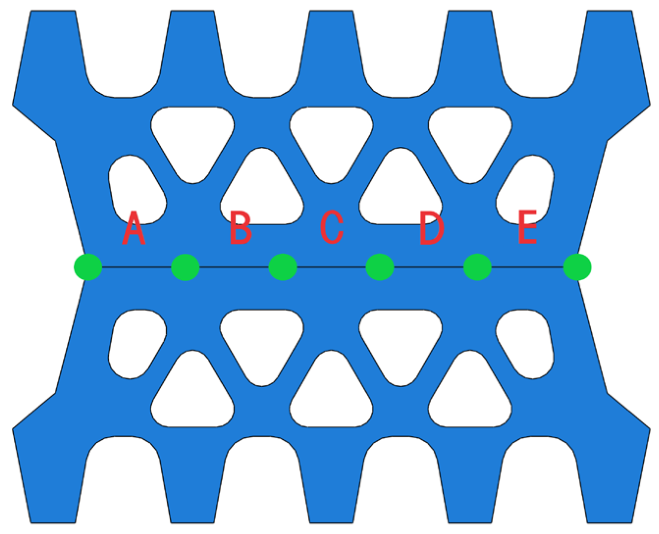
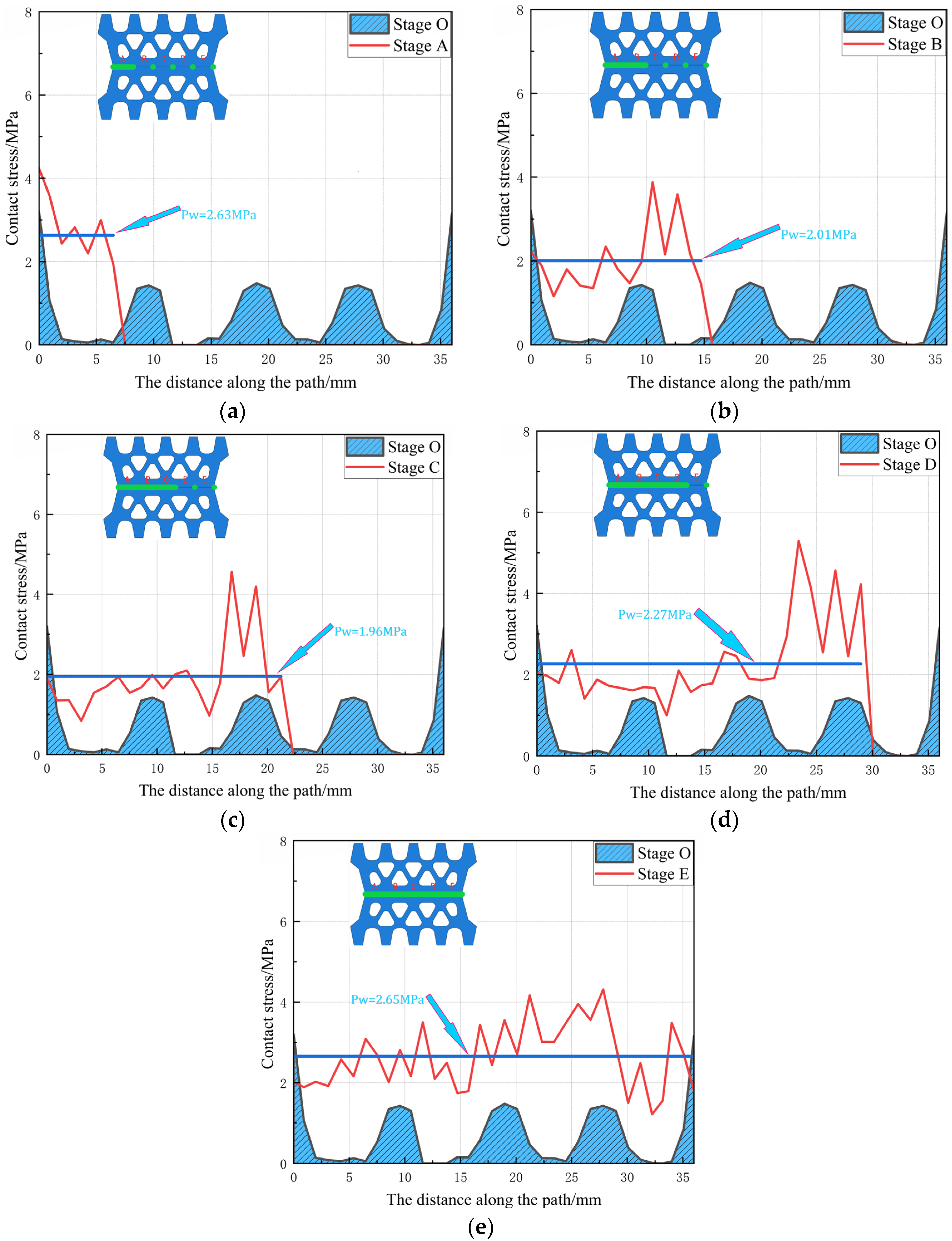
From Figure 15, it is clear that the uneven distribution of the permeation stress barrier, which is formed by the initial contact stress, significantly affects the waterproof performance of the sealing gasket at the junction of shield tunnel segments. To further explore the relationship between the permeation stress barrier and the waterproof performance of the gasket, the interface between the sealing gaskets is divided into five stages, as shown in Figure 20. In each stage, when the water surpasses the flow resistance caused by the contact stress of the sealing gasket, seepage occurs between the sealing gaskets. By using the pressure-weighted average value of water when the gasket is breached as a threshold to represent the waterproof performance, we can provide a quantitative reference for the waterproof performance of the elastic rubber sealing gasket under specific conditions.
In order to investigate the entire waterproof failure process of the elastic sealing gasket, a comprehensive simulation was conducted under the influence of water pressure, revealing the evolution of water pressure throughout the seepage process, as shown in Figure 21. Stage 0 represents the initial contact stress formed after the compression of the elastic sealing gasket, indicating the absence of seepage at this stage. Upon exposure to water pressure, the water pressure initially acts on the left side of the elastic sealing gasket. As the water pressure increases, the water breaches the first part of the interface between the sealing gaskets, leading to the separation of the first part of the sealing gasket, with the waterproof threshold of Part A being 2.63 MPa. Subsequently, sections B, C, D, and E are gradually breached by water, with corresponding waterproof thresholds of 2.01 MPa, 1.96 MPa, 2.27 MPa, and 2.65 MPa, respectively. When the waterproof threshold reaches 2.65 MPa, the contact surface of the elastic sealing gasket is completely penetrated, allowing pressurized water to enter the interior cavity of the shield tunnel segment, thus resulting in the failure of the waterproof system. By analyzing the waterproof thresholds of different sections, a better understanding of the impact of the permeation stress barrier on the waterproof performance of the sealing gasket can be obtained.
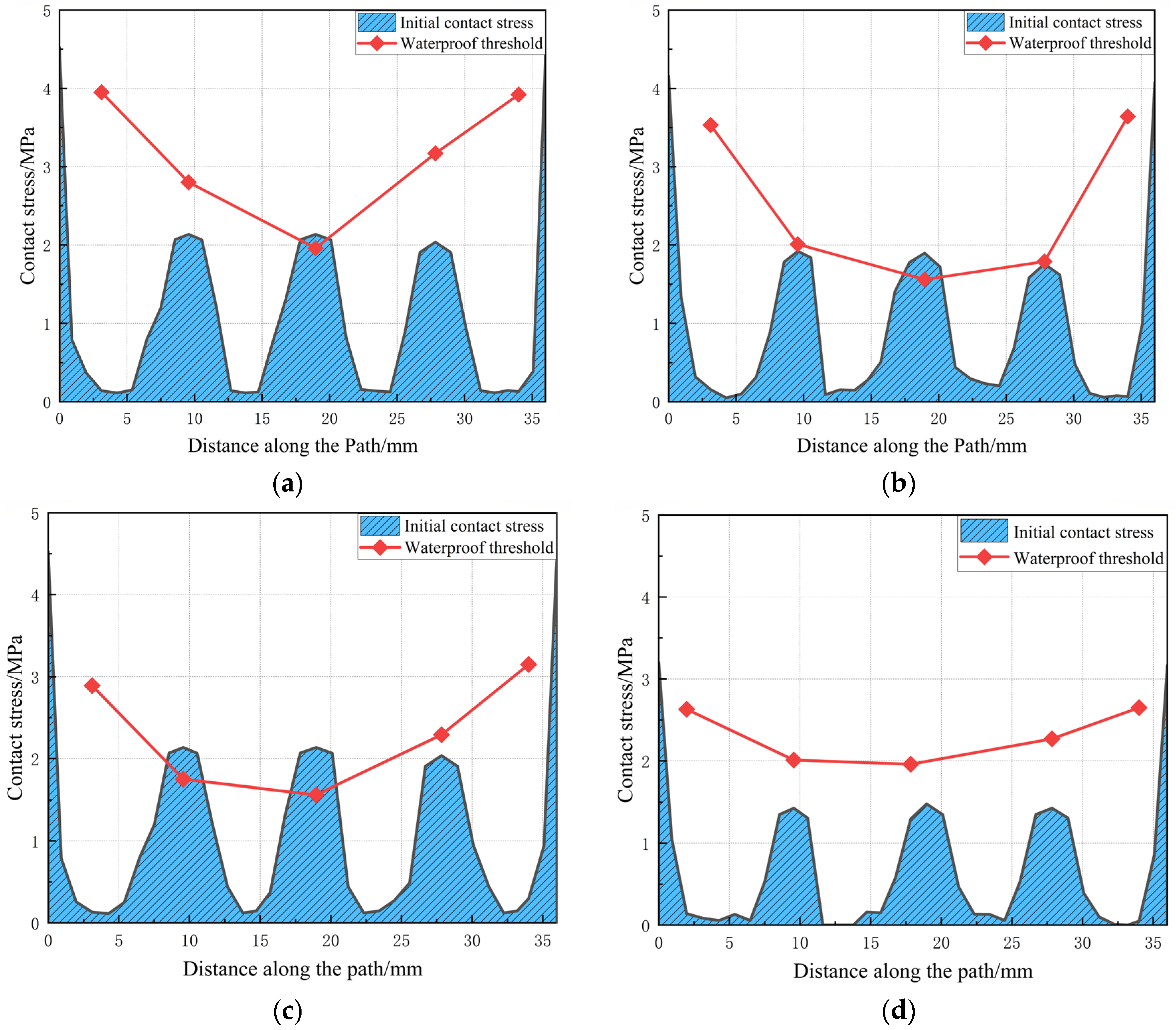
The waterproof capacity of the joint refers to the maximum ability of the joint to prevent water from entering when it is subjected to pressurized water. The value of the waterproof capacity is determined by the waterproof thresholds at different stages. Figure 22 displays the waterproof thresholds for opening distances of 4 mm, 6 mm, 8 mm, and 10 mm. From the figure, it is evident that as the opening distance increases, the waterproof thresholds gradually decrease at each stage. The trend of the waterproof thresholds is similar to that of the initial contact stress between the sealing gaskets, with high values at both ends and low values in the middle.

6. Discussion and Conclusions

6.1. Discussion

Although the Coupled Eulerian-Lagrangian (CEL) method employed in this paper can simulate the dynamic seepage process of water and the interaction between water and the sealing pad, there are still some issues that need further investigation.
1.
Currently, this paper primarily focuses on the waterproof failure mechanism caused by water pressure acting on elastic rubber sealing pads in the open state. However, the waterproof failure mechanism of sealing pads in staggering situations has not been addressed. Future research could delve deeper into this aspect, conducting more extensive exploration and analysis to comprehensively understand the waterproof performance of sealing pads under different conditions.
2.
When analyzing the waterproof failure mechanism of elastic rubber sealing pads, this paper has not yet considered the influence of long-term effects such as fatigue and stress relaxation that may occur during prolonged use. These long-term effects could significantly impact the waterproof performance of the sealing pads. Therefore, the next step in research could involve a deeper investigation into the waterproof failure mechanism of elastic rubber sealing pads under prolonged water pressure. This would further refine the theoretical framework of waterproof design and propose more accurate definitions and criteria for safety factors, providing more reliable guidance for waterproof design.

6.2. Conclusions

To explore the waterproofing performance of the gasket at the joints of tunnel segments, the assembly compression process of the gasket at the joints of subway shield tunnel segments was simulated using the finite element software ABAQUS. Additionally, a coupled Eulerian-Lagrangian (CEL) method was employed to numerically simulate the leakage failure process of the gasket waterproofing system. By conducting dynamic seepage simulations of the waterproofing systems with different opening distances of the gasket, the following conclusions can be drawn:
1.
Throughout the entire process, from segment assembly to leakage at the joint, the elastic rubber sealing gasket undergoes four key stages: gasket compression, pressure water extrusion, water wedging, and final leakage. Under the action of pressure water, the interface between the sealing gaskets is initially separated, creating gaps. With increasing water pressure, the interface between the gaskets gradually opens until the pressure water finally breaches, resulting in leakage at the joint.
2.
Analysis reveals that the permeation stress barrier formed by the initial contact stress exhibits a “W” symmetric distribution, with the contact stress peak at both ends of the interface approximately twice that of the middle. The contact stress at the gasket-groove interface undergoes intermittent changes throughout the entire water seepage process.
3.
By using the weighted average of water pressure to determine the waterproof threshold at each stage of the gasket, it is observed that the waterproof threshold of the elastic rubber gasket is dependent on the seam opening size. The waterproof threshold of the elastic gasket decreases with increasing seam opening size; when the opening size of the elastic gasket is small, its waterproof threshold is larger, indicating stronger waterproofing capability.

Author Contributions

Conceptualization, X.W. and S.L.; methodology, D.H.; software, D.H.; validation, X.W., D.H. and S.L.; formal analysis, X.W.; investigation, S.L.; resources, X.W.; data curation, D.H.; writing—original draft preparation, D.H.; writing—review and editing, X.W.; visualization, D.H.; supervision, S.L.; project administration, X.W.; funding acquisition, S.L. All authors have read and agreed to the published version of the manuscript.

Funding

This research was funded by the National Natural Science Foundation of China (No. 51309100), Science and Technology Project of Henan Province (No. 222102320135), (No. 222102320231).

Data Availability Statement

Data are contained within the article.

Conflicts of Interest

The authors declare no conflict of interest.

References

  1. Xue, Y.D.; Zhang, S.; Zhou, M.L.; Zhu, H.H. Novel SfM-DLT method for metro tunnel 3D reconstruction and Visualization. Undergr. Space 2021, 6, 134–141. [Google Scholar] [CrossRef]
  2. Zhang, Y.; Jia, Y. Joint Waterproofing Design for River-crossing Shield Tunnel of Nanjing Subway, Line 10. China Build. Waterproofing 2013, 18–25. [Google Scholar] [CrossRef]
  3. Yang, J.S.; Fu, Q.; Yu, L.J.; Wang, T.; Wei, Q.; Li, W.; Wang, S.W. Research Progress of Rubber Modified Acrylate Pressure Sensitive Adhesive. J. Petrochem. Univ. 2023, 36, 8. [Google Scholar]
  4. Girnau, G. Lining and waterproofing techniques in Germany. Tunn. Tunn. Int. 1978, 10, 36–45. [Google Scholar]
  5. Paul, S.L. Hydraulic Pressure and Stiffness Tests of Gaskets for Precast Concrete Tunnel Liner Segments; Unpublished Report; Department of Civil Engineering, University of Illinois at Urbana-Champaign: Urbana, IL, USA, 1984. [Google Scholar]
  6. Liu, Y.K.; Wu, Y.; Li, W.H.; Zhang, Q.S.; Liu, R.T.; Bai, J.W.; Li, W. Development of a water leakage model test system and investigation of the water leakage behavior in subsea shield tunnels during operation. Measurement 2024, 233, 114691. [Google Scholar] [CrossRef]
  7. Zhang, G.L.; Zhang, W.J.; Cao, W.Z.; Wang, B.D.; Lai, T.T.; Guo, W.S.; Gao, P. A novel test setup for determining waterproof performance of rubber gaskets used in tunnel segmental joints: Development and application. Tunn. Undergr. Space Technol. 2021, 115, 104079. [Google Scholar] [CrossRef]
  8. Zhao, M.; Ding, W.Q.; Peng, Y.C.; Shen, B.W.; Guo, X.H.; Yang, L.S. Experimental Study on the Reliability of Shield Tunnel Segment Joints to Remain Watertight Under High Water Pressure. Mod. Tunn. Technol. 2013, 50, 87–93. [Google Scholar]
  9. Shalabi, F.I.; Cording, E.J.; Paul, S.L. Concrete segment tunnel lining sealant performance under earthquake loading. Tunn. Undergr. Space Technol. 2012, 31, 51–60. [Google Scholar] [CrossRef]
  10. Ding, W.Q.; Wang, Q.S.; Qiao, Y.F.; Jin, Y.L. Experimental investigation on waterproofing performance of segmental joint with double gaskets for shield tunnel. Undergr. Space 2022, 7, 898–910. [Google Scholar] [CrossRef]
  11. Karpenko, M.; Skačkauskas, P.; Prentkovskis, O. Methodology for the composite tire numerical simulation based on the frequency response analysis. Eksploat. Niezawodn. 2023, 25, 1–11. [Google Scholar] [CrossRef]
  12. Yan, Q.X.; Zhong, H.J.; Zhang, C.; Zhao, Z.C.; Wen, Y.X.; Wang, P. Novel numerical model to simulate water seepage through segmental gasketed joints of underwater shield tunnels considering the superimposed seepage squeezing effect. Undergr. Space 2023, 13, 104–120. [Google Scholar] [CrossRef]
  13. Xu, L.; Wu, G.Z. Some Forms of Strain Energy Function for Rubber with Finite Element Analysis. China Rubber Ind. 1999, 46, 707–711. [Google Scholar]
  14. Zhang, T.; Huo, Y.P.; Wu, Y.; Yin, Z.N.; Wen, Y.X.; Yan, Q.X. Test and Numerical Simulation of Mechanical Performance of Waterproof Gasket in Shiel Tunnel Under River. Railw. Eng. 2022, 62, 128–133. [Google Scholar]
  15. Ouyang, W.B. Mechanical Test and Numerical Analysis of Elastic Gaskets of Shield Tunnels. Tunn. Constr. 2013, 33, 933–936. [Google Scholar]
  16. Gong, C.J.; Ding, W.Q.; Soga, K.; Mosalam, K.M. Failure mechanism of joint waterproofing in precast segmental tunnel linings. Tunn. Undergr. Space Technol. 2019, 84, 334–352. [Google Scholar] [CrossRef]
  17. Zhang, Y.Z.; Feng, S.M.; You, G.G.; Wen, Z.J. Study on Waterproof Mechanism of Shield Tunnel Joints Considering Water Pressure Process. Tunn. Constr. 2020, 40, 1594–1601. [Google Scholar]
  18. Sun, L.W. Numerical Analysis of Waterproof Mechanism of Shield Tunnel Joint Based on Applied Water Pressure. Tunn. Constr. 2018, 38, 603–610. [Google Scholar]
  19. Zhang, J.W.; Chen, Y.Y.; Feng, Q.K. Characteristic parameters’ optimization based on contact pressure of sealing gasket for segmental joints. Adv. Mech. Eng. 2020, 12, 1687814020943360. [Google Scholar]
  20. Xie, J.C.; Huang, X.H.; Jin, G.L. Analytical model for the sealant performance of tunnel gasketed joints based on multi-scale contact and percolation theories. Undergr. Space 2024, 14, 319–337. [Google Scholar] [CrossRef]
  21. Karpenko, M.; Bogdevičius, M. Investigation of hydrodynamic processes in the system—“pipeline-fittings”. In Proceedings of the TRANSBALTICA XI: Transportation Science and Technology: Proceedings of the International Conference TRANSBALTICA, Vilnius, Lithuania, 2–3 May 2019; Springer International Publishing: Berlin/Heidelberg, Germany, 2020; pp. 331–340. [Google Scholar]
  22. Zhang, J.H.; Li, Y.; Liu, X.W.; Sun, Z.B.; Cao, G.Q. Statistical analysis of shield tunnel disease based on horizontal convergence in soft clay. China Civ. Eng. J. 2020, 53, 124–130. [Google Scholar]
  23. Dai, X.Q.; Wang, J.; Li, Z.X.; Han, J.Y.; Wang, W.W.; Li, K.J. Research on current situation of causes and prevention measures of water leakage diseases in shield tunnels. Yangtze River 2022, 53, 186–192. [Google Scholar]
  24. Liu, Y.J. Study on Structural Safety of Shield Tunnel and Vehicle Dynamic Behavior under Disease Condition in Beijing Subway; Beijing Jiaotong University: Beijing, China, 2019. [Google Scholar]
  25. Shao, H.; Wang, R. Analysis of the Influence Factors and Its Characteristics of Metro Shield Tunnel Defects in Shanghai. Mod. Tunn. Technol. 2018, 55, 922–929. [Google Scholar]
  26. Li, P. Study on Waterproofing Mechanism and Design Method of the Double Sealing Gaskets for Shield Tunnel under High Water Pressure; Southwest Jiaotong University: Chengdu, China, 2021. [Google Scholar]
  27. Yao, X.H.; Huang, Y.T.; Ou, Z.C.; Liu, X.M.; Hu, B.R. CEL Algorithm-Based Analysis of Dynamic Characteristics of Amphibious Aircraft Landing on Water. J. South China Univ. Technol. (Nat. Sci. Ed.) 2015, 43, 110–115. [Google Scholar]
  28. Wang, W.C. Research on Ice-Soil-Pipeline Coupling Model Based on CEL Method; China University of Petroleum: Beijing, China, 2021. [Google Scholar]
  29. Yan, S.W.; Lin, S.; Huo, Z.L.; Chu, J.; Guo, W. Coupled Eulerian-Lagrangian finite element analysis of suction caisson penetration processes under hydraulic pressure. Rock Soil Mech. 2017, 38, 247–252. [Google Scholar]
  30. Zhang, Z.X.; Gu, G.S.; Huang, X.; Zhang, J.Q.; Zhang, C. Experimental Study on Waterproof Performance of Embedded Sealing Gasket of Segment Joint for a Shield Tunnel. Tunn. Constr. 2019, 39, 1402–1411. [Google Scholar]
  31. Zhang, Q.; Shi, J.W.; Suo, S.F.; Meng, G.Y. Finite element analysis of rubber materials based on Mooney-Rivlin models and Yeoh models. China Synth. Rubber Ind. 2020, 43, 468–471. [Google Scholar]
  32. Wang, H.K.; Yu, Y.; Sun, Z.Z.; Xu, W.S. Numerical study on the implosion of hollow slender cylindrical shells and the induced chain failure. J. Ship Mech. 2023, 27, 1208–1220. [Google Scholar]
  33. Gong, C.J.; Ding, W.Q.; Soga, K.; Mosalam, K.M. Sealant behavior of EPDM gaskets in TBM tunnel segmental joints. In Proceedings of the ARMA US Rock Mechanics/Geomechanics Symposium, San Francisco, CA, USA, 25–28 June 2017; p. ARMA-2017-0563. [Google Scholar]
  34. Zhou, W.F.; Liao, S.M.; Men, Y.Q. A fluid-solid coupled modeling on water seepage through gasketed joint of segmented tunnels. Tunn. Undergr. Space Technol. 2021, 114, 104008. [Google Scholar] [CrossRef]
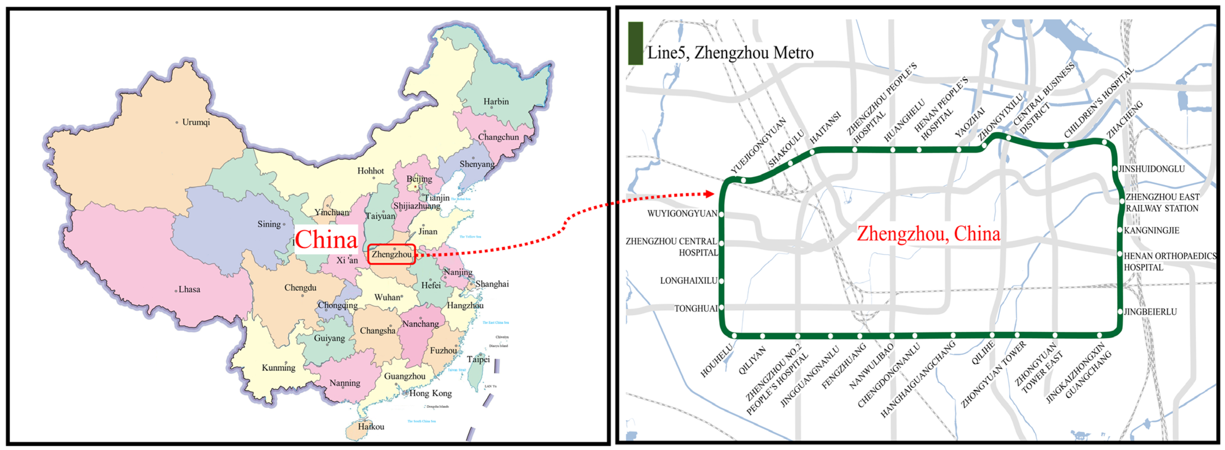
Figure 1. Tunnel location map.
Water 16 01661 g001
Figure 2. Elastic rubber gasket diagram.
Water 16 01661 g002
Figure 3. Model schematic: (a) Cross section diagram of shield tunnel; (b) Sealing gasket cross-sectional view.
Water 16 01661 g003
Figure 4. Survey results figure of leakage water types in shield tunneling [23,24,25].
Water 16 01661 g004
Figure 5. Map of leakage water locations: (a) Annular seam leakage; (b) Transverse seam leakage; (c) Grouting hole leakage; (d) T-type seam leakage.
Water 16 01661 g005
Figure 6. Lagrangian mesh schematic diagram.
Water 16 01661 g006
Figure 7. Euler mesh schematic diagram.
Water 16 01661 g007
Figure 8. Schematic diagram of assigning materials to Eulerian regions via discrete fields.
Water 16 01661 g008
Figure 9. Fluid–solid coupling analysis model diagram.
Water 16 01661 g009
Figure 10. Euler body and reference body area setting diagram.
Water 16 01661 g010
Figure 11. Sealing gasket contact definition diagram: (a) Contact between Seal Gasket and its own structure and Holes; (b) Contact between the seal gasket and grooves; (c) Contact between seal gaskets.
Water 16 01661 g011
Figure 12. Model validation diagram.
Water 16 01661 g012
Figure 13. Seepage form diagram of different stages.
Water 16 01661 g013
Figure 14. Variation curve of average contact stress between sealing gaskets.
Water 16 01661 g014
Figure 15. Initial contact stress diagram for seal gasket-seal gasket interface.
Water 16 01661 g015
Figure 16. Contact stress diagram between gasket and gasket under 6 mm opening.
Water 16 01661 g016
Figure 17. Contact stress diagram between gasket and gasket under 10 mm opening.
Water 16 01661 g017
Figure 18. Six-millimeter opening gasket-groove contact stress diagram.
Water 16 01661 g018
Figure 19. Ten-millimeter opening gasket-groove contact stress diagram.
Water 16 01661 g019
Figure 20. Sealing gasket interface diagram.
Water 16 01661 g020
Figure 21. Waterproof threshold diagram for various stages of the seal gasket-seal gasket interface: (a) Stage A; (b) Stage B; (c) Stage C; (d) Stage D; (e) Stage E.
Water 16 01661 g021
Figure 22. Waterproof threshold diagram of gasket under different opening amount: (a) Open 4 mm; (b) Open 6 mm; (c) Open 8 mm; (d) Open 10 mm.
Water 16 01661 g022
Table 1. Types and definitions of leakage water in shield tunneling.
TypeDefinition
Wet stainedMoist spots with noticeable color changes on the inner surface of tunnel segments.
Water seepageInfiltration of water into segments, resulting in moisture on the inner surface of segments.
DribblingWhen the amount of water reaches a certain level, it drops from above.
Mud leakage sandWater mixed with soil particles, sediment, and other materials from behind the segments flows out from the leakage area.
Table 2. Leakage location statistical table.
Leak LocationLeakage Quantity/PieceLeakage Ratio/%
T-type seam1050
Circumferential seam315
Transverse joint420
Bolt hole210
Reserved grouting hole15
Table 3. Mapping relationship between H A parameters.
Rubber   Hardness   ( H A ) C 10 C 01
650.600.15
660.620.16
670.650.16
680.680.17
690.710.18
700.740.19
Table 4. Initial state parameters.
c 0 m m / s s η ρ 0 t / m m 3 U P m m / s
1.483 × 106001.00 × 10−91.00 × 10⁻⁹
Disclaimer/Publisher’s Note: The statements, opinions and data contained in all publications are solely those of the individual author(s) and contributor(s) and not of MDPI and/or the editor(s). MDPI and/or the editor(s) disclaim responsibility for any injury to people or property resulting from any ideas, methods, instructions or products referred to in the content.