Article

Guidelines for the Energetic Characterization of a Portable Drip-Type Rainfall Simulator for Soil Erosion Research

by
Maria Angela Serio
1,
Francesco Giuseppe Carollo
1,
Roberto Caruso
1 and
Vito Ferro
1,2,*
1
Department of Agricultural, Food and Forest Sciences, University of Palermo, 90128 Palermo, Italy
2
National Biodiversity Future Center, 90133 Palermo, Italy
*
Author to whom correspondence should be addressed.
Water 2024, 16(15), 2100; https://doi.org/10.3390/w16152100
Submission received: 14 June 2024 / Revised: 19 July 2024 / Accepted: 24 July 2024 / Published: 25 July 2024

Abstract

:
The results of the energetic characterization of two drip-type rainfall simulators, differing in the length of their capillary tubes, are presented. The rainfall kinetic power and momentum were measured using a single capillary tube and applying weighing and photographic techniques to determine the raindrop mean equivalent diameter and fall velocity, respectively. The measurements highlighted that the simulated rainfall intensity is the only variable affecting raindrop diameter, and the increase in the capillary tube length produces a reduction in rainfall intensity and raindrop diameter. Finally, an empirical relationship relating fall velocity with raindrop falling height and diameter found in the literature was developed and positively tested using both the experimental data of the velocity measurements from the present research and the literature. Relationships to estimate the rainfall kinetic power and momentum based on the knowledge of mass and raindrop falling height were proposed and positively tested for the two simulators in the present investigation. In conclusion, operative guidelines for a drip-type simulator characterization are proposed in this paper, considering that the knowledge of the geometric characteristics of the capillary tube, pressure head, and falling height values are fundamental to having a complete energetic characterization of the rainfall simulator.

1. Introduction

Rainfall is the most important climatic variable influencing erosive processes, and its erosivity, i.e., the capability of rainfall to cause erosion, reflects the erosion phenomena due to the impact of raindrops and surface runoff, both affecting the detachment and transport of soil particles [1,2].
Rainfall erosivity, often referred as the R-factor in Universal Soil Loss Equation (USLE)-based models, can be represented both as its kinetic energy per unit time and surface area, called kinetic power, Pn (J m−2 s−1), and its momentum per unit time and surface area, M (N m−2) [3]. Since rain erosivity is assessed by summing the contributions attributable to each raindrop constituting the precipitation, its determination requires information on both the terminal velocity of raindrops, vt (m s−1), and their drop size distribution (DSD).
Rainfall simulation holds significant interest in water erosion research, as it allows for direct control of the erosive agent, which is not feasible with natural precipitation. The use of simulated rainfall with known energetic characteristics enables a deeper understanding of the dynamics of several sub-processes involved in erosion phenomena, such as rain detachment or establishing the relationship between interrill erosion and precipitation intensity. Moreover, the ability to simulate rainfall events with predetermined characteristics at specified times substantially reduces experimentation time. Rainfall simulation also ensures repeatability and comparability of experiments under controlled conditions and over relatively short time periods, which is generally not achievable with natural rainfall. Thus, rainfall simulators are useful devices for investigating several hydrological and erosive processes.
Small portable rainfall simulators have been used worldwide by different research groups for many years and, since 1938, more than 100 rainfall simulators with plot dimensions of <5 m2 (most of them <1 m2) have been developed [4,5,6,7,8,9,10,11,12,13,14,15,16,17,18,19,20,21]. Moreover, the absence of standardization of rainfall simulation and test conditions makes it difficult to compare the results available in the literature [17,22,23,24].
The rainfall simulator (model type 09.06) proposed by Kamphorst [7,25] is one of the most used. This small device, easily transportable and widely applied for soil conservation surveys, developed at Wageningen Agricultural University and first described by Kamphorst [7], was recently characterized from an energetic point of view [21]. This simulator has a sprinkler with 49 capillary tubes (10 mm long and an inner diameter of 0.6 mm) in fixed positions (Figure 1). This represents a limitation because drops flowing from a single tube always impact the same point during an experimental run. The pressure head on the capillaries can be increased or decreased by moving an aeration tube upward or downward, and a built-in pressure regulator, based on Mariotte’s bottle principle, allows for maintaining a constant rainfall intensity value during the rainfall simulation. According to Kamphorst [7], the pressure head regulation is oriented to correct for the influence of the viscosity, which depends on the water temperature. In fact, the device was not designed to be used to produce showers of different intensities but to obtain a standard rain shower. However, Bagarello et al. [26] proved that rainfall intensity can be significantly changed by moving the aeration tube in this simulator and developed an empirical relationship between rainfall intensity, the position of the aeration tube, and the water temperature.
It is known that the main properties of simulated rainfall are its spatial distribution, drop size distribution (DSD), the falling velocity of the drops, and kinetic power. Over the years, these variables have been widely investigated for natural precipitation and rarely for simulated precipitation. A summary of major requirements for small portable rainfall simulators is reported by Iserloh et al. [21]. These authors studied and compared the performance of 13 different rainfall simulators located in several European research institutions, from the perspectives of dimension, intensity, and energetic distribution.
In soil erosion processes, one of the dynamic rainfall characteristics is raindrop impact velocity, which depends on the height of fall of each raindrop, h (m), and its diameter, D (m). Numerous studies [27,28,29,30,31,32,33] demonstrate that for a drop having a diameter equal to D, the falling velocity v (m s−1) grows with h and, for h > 20 m, the fall velocity assumes its terminal value, vt, (m s−1), corresponding to an equilibrium condition between the gravitational power and the aerodynamic resistance. Few terminal velocity measurements of natural raindrops are available in the literature [28,29], and the empirical relationships between vt and D are based on measurements of single simulated raindrops that fall in stagnant air [28,29,30,31,32,33].
Characterizing the rainfall produced by a rainfall simulator fed at a pressure of about 2 bar, at a height of 2 m, and a rainfall intensity value of 40 mm h−1, Ries et al. [34] stated that most of the inaccuracy is due to the drop fall velocity measurements [35,36]. In particular, they indicated that small drops moved with “an unrealistic high velocity” and that an available height of 2 m is not sufficient for accelerating and reaching terminal velocity. Moreover, the high fall velocity of very small drops prevented the laser disdrometer from recognizing all the raindrops.
Abudi et al. [20] applied a digital camera capable of recording video at 8000 FPS (frames per second) to monitor simulated falling drops (in the range of 1–5.2 mm), falling from a height of 4.5 m, and calculate their size and velocity. They found that this height allowed only small drops (1–3 mm) to arrive almost at the terminal velocity, while bigger drops (3–5 mm) were more affected by the drag force due to the viscosity of air, requiring a longer freefall path to reach their terminal velocity.
Iserloh et al. [21] energetically characterized the Kamphorst simulator using raindrop size distribution and falling velocity measurements carried out by the Thies Laser Precipitation Monitor. These authors did not provide information on the applied operating conditions (pressure head, water temperature) and used the device in its standard operation setting (rainfall intensity equal to 360 mm h−1, falling height set at 40 cm). They found that, for this rainfall simulator, the kinetic power values are greater than those calculated for natural rainfall, because the Kamphorst simulation is characterized by a very short test duration, and it also produces large and high-energy drops.
Carollo et al. [37] energetically characterized the Kamphorst simulator by using a weighing method for drop mass determination and a photographic technique for drop fall velocity measurements. At first, the rainfall uniformity distribution of the simulator was positively verified considering several pressure heads (ranging from 1.9 cm to 11.9 cm) and water temperatures (from 24 °C to 27 °C), achieving a uniformity coefficient ranging from 96 to 99%. Then, using a single capillary tube, the simulator was characterized in terms of kinetic power and momentum. They observed that, for the experimental set-up considered in their investigation (pressure head varying from 1.9 to 6.9 cm, water temperature ranging from 16 °C to 26 °C, and falling height less than 1.3 m), this simulator produces large drops (0.5–0.61 mm) with fall velocities comparable to that of a body falling free in a vacuum, which is the maximum achievable velocity value. The authors also proposed two empirical equations for the rainfall kinetic power and momentum estimations, allowing the characterization of the rainfall simulator by knowing the falling height and the simulated rainfall intensity.
Using a photographic technique, Laws [30] measured the velocity of raindrops having diameters ranging from 1 to 6 mm and falling in still air from a height, h, varying from 0.5 to 20 m. Laws’ [30] measurements suggested a clear dependence of v by fall height and raindrop diameter. In particular, the analysis highlighted that for h < 6 m, the growth rate of the falling velocity increases with the raindrop diameter, while for h > 6 m, an increase in h does not produce an increase in the falling velocity, because it is only dependent on the raindrop diameter.
Above all for meteorological aims, many authors propose relationships to estimate raindrop falling velocity as a function of the diameter of the drop and the atmosphere density and viscosity, depending on the fall heights [3,31,38,39,40,41,42,43,44,45,46,47]. For describing the variation in the terminal velocity with the diameter of the drop, which in nature might be expected to deform from the spherical shape as it falls through the air, Best [40] used measurements of vt carried out by Spilhaus [39] to propose three empirical relationships to estimate v.
Assouline et al. [48] evaluated the raindrop velocity at the soil surface as a function of the falling height, considering fall velocity measurements carried out by Laws [30] and Wolfs [49]. For simulated rainfalls, they suggested that drop velocity at the soil surface is comparable to the terminal velocity of equivalent diameters for falling heights greater than 5.5 m.
Leone and Pica [3], using raindrop falling velocity measurements carried out in laboratory conditions by Laws [30] and Gunn and Kinzer [31], proposed a relationship to estimate v by the raindrop diameter, which assumes the maximum value for D equal to 0.5 cm. Moreover, in this analysis, the authors considered only raindrop diameters varying in the range of 0.10–0.55 cm since for D < 0.10 cm, the drop has both a low terminal velocity and a small mass, producing negligible kinetic power. Instead, for D > 0.55 cm the raindrops are unstable and tend to break up before reaching their terminal velocity [50].
Considering that for natural rainfall the terminal velocity increases for D < 0.56 cm, until which it seems to be constant, and using the measurement carried out by many researchers [28,29,30,31,32,33], Ferro [47] deduced the following relationship:
v = V S 1 e a S D
where VS and aS are parameters depending on h. For h greater than or equal to 20 m or for natural rainfalls, the raindrop reaches its terminal velocity, and thus in Equation (1), VS and aS are equal to 9.5 m s−1 and 6 cm−1, respectively. For falling height, h, less than 20 m, Equation (1) can be also used for quantifying the raindrop impact velocity, which is less than the terminal one [51]. Equation (1) has been widely used to estimate terminal velocity for natural precipitation in the Mediterranean area [27,51,52,53,54] and to deduce many theoretical relationships to estimate rainfall kinetic power, Pn (J m−2 s−1), and rainfall momentum, M (N m−2), by knowing the raindrop size distribution.
Since the height of the commonly used rainfall simulators does not allow the achievement of the terminal velocity values of natural rainfall, the application of Equation (1) requires a choice of VS and aS values that correspond to the falling height of the investigated simulator.
The aim of this investigation is to give instructions for the characterization of two drip rainfall simulators, regarding fall velocity, mass, and thus the kinetic power and momentum of simulated raindrops hitting the soil. New empirical relationships to estimate the fall velocity, kinetic power, and momentum for simulated rainfall are also proposed.

2. Materials and Methods

2.1. Experimental Set-Up

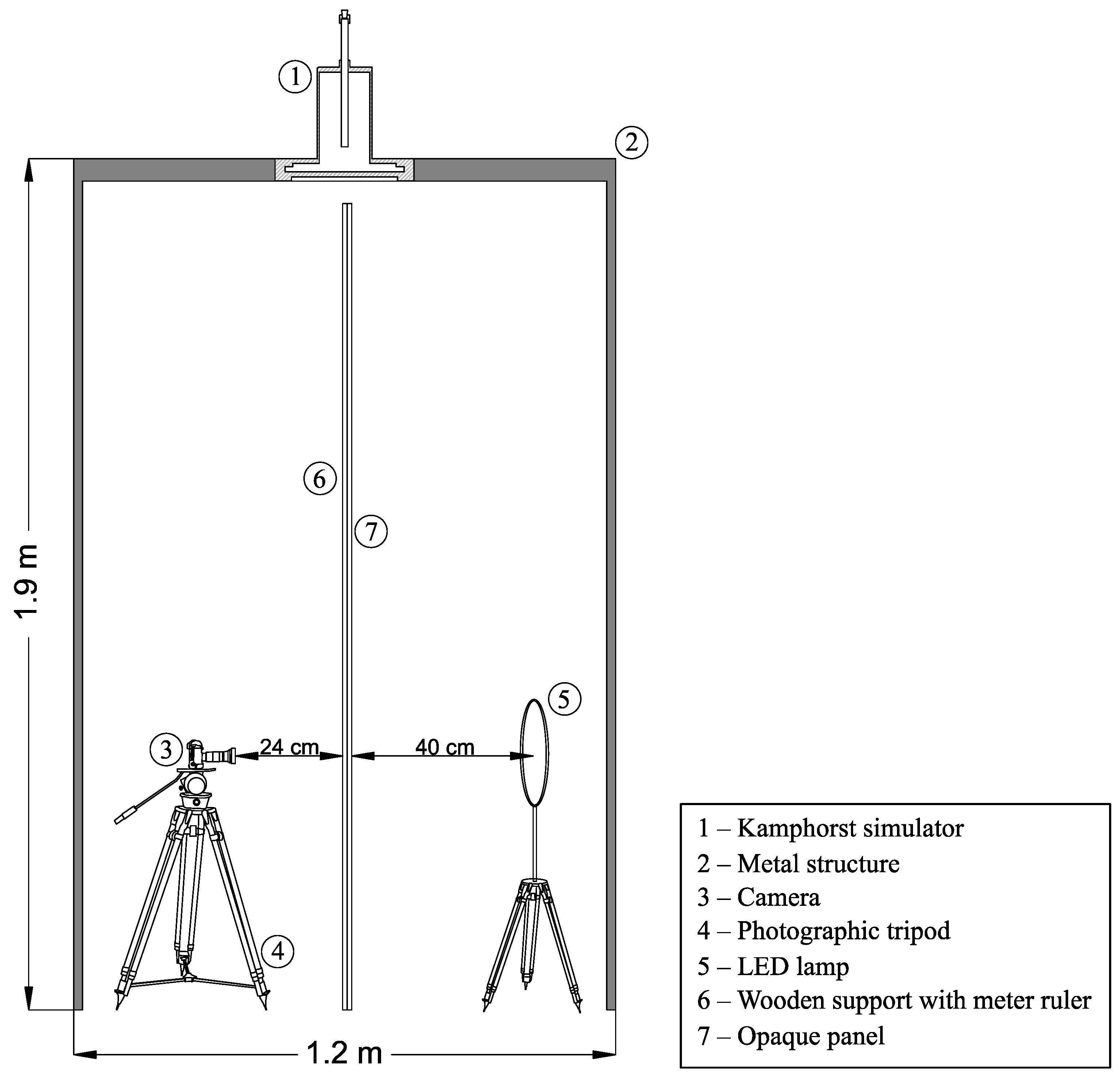
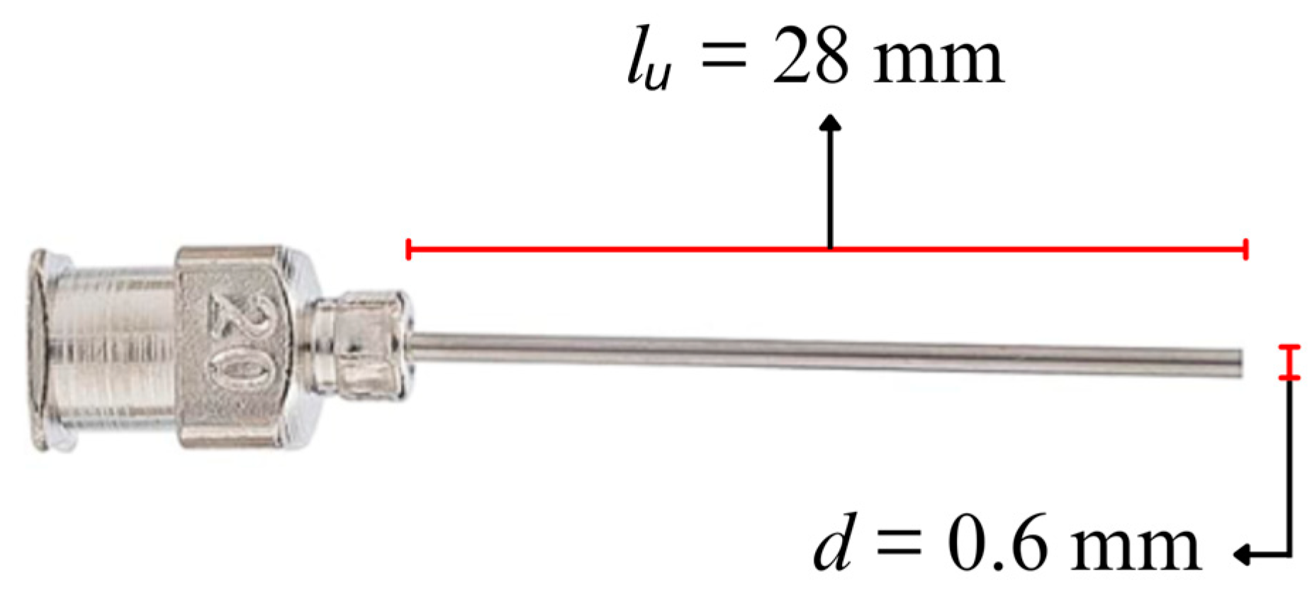
The experimental setup (Figure 2), located in the laboratory of the Department of Agricultural, Food, and Forest Sciences of the University of Palermo (Italy), consists of a Kamphorst rainfall simulator (KS) (model type 09.06) [25] (Figure 1), placed inside a wooden support positioned above a metal structure (1.9 m high and 1.2 m wide). To explore different rainfall characteristics from those supplied by the original Kamphorst simulator (KS), a new capillary tube was also considered—a metal capillary tube (Figure 3) with a length of 28 mm and an inner diameter of 0.6 mm, made by Benecreat, which was placed inside the dripping plate and fixed with hot glue.
The installation is also equipped with a stopwatch, a scale (model MP-3000G, made by Chyo), a foldable metal ladder, a tank for water storage, a mobile phone camera, and an opaque color background panel. The frame rate of the camera, which records slow motion video at 720p resolution, is 480 FPS (frames per second). The mobile phone is supported and leveled by a vertically extendable photographic tripod, allowing the positioning of the camera lenses in parallel with the falling direction of the simulated rain. Since the minimum height at which the camera can be positioned above the photographic tripod is 60 cm, the maximum explorable falling height for the considered experimental setup is equal to 1.3 m. A meter ruler was also placed in parallel with the falling direction of the drops to calculate the distance traveled by a raindrop during its fall. During the recordings, the distance between the camera lenses and the ruler was 24 cm. An LED lamp, opposite the camera and 40 cm behind the background panel, was also used to guarantee raindrop recognition in the frames.

2.2. Test Procedure to Determine Rainfall Characteristics and Calculate Rainfall Kinetic Power and Momentum

To characterize the rainfall simulators of the present investigation from an energy point of view, a standardized test procedure was performed using different values of water temperatures, T (°C), and pressure heads, H (m). For each HT pair, which was repeated three times, the water volume corresponding to 100 water drops flowing out by the selected capillary tube was collected and weighed, also recording the sampling time. For the modified Kamphorst simulator (MKS), which has a capillary tube 28 mm long with an inner diameter of 0.6 mm, and for the highest-pressure head values (H ≥ 7 cm), the count of the number of drops was conducted with the support of slow-motion video, since the drop formation rate was very fast and did not allow naked-eye measurements.
The knowledge of the weight of the water volume, m (kg), referred to as the considered number of drops, nD, allows for determining the mean mass of a single water drop, mSD (kg), as follows:
m S D = m n D
Therefore, its volume, VSD (m3) can be obtained:
V S D = m S D ρ
in which ρ is the water density (kg m−3), which depends on the water temperature. Considering that the water drop generated by the nozzle is spherical, its diameter, D, expressed in cm, is calculated as:
D = 2 3   V S D 4   π 3
The photographic method was not considered for the calculation of the raindrop diameter because of the characteristics (frame rate and resolution) of the mobile phone used in this investigation, which didn’t allow for capturing the raindrop size due to the motion blur effect. Conversely, the knowledge of the VSD by the weighing technique allowed us to consider the three dimensionality of the raindrop for the calculation of its diameter (Equation (4)).
Considering H values equal to 2 cm, 5 cm, and 7 cm for KS and equal to 2 cm, 4 cm, 6 cm, 8 cm, 10 cm, and 12 cm for MKS, and water temperature ranging from 16 °C to 26.1 °C for KS and from 17.7 °C to 19.1 °C for MKS, the fall velocity of a droplet v (m s−1) was measured by a photographic method. For each H value, four falling height intervals (h = 0.33–0.42 m; h = 0.52–0.61 m; h = 0.85–0.96 m; and h = 1.21–1.30 m) were also considered. Measuring the displacement of a single raindrop between two following frames, looking at its upper tip, and knowing the frame rate, the raindrop fall velocity, v (m s−1), was calculated. For the Kamphorst rainfall simulator (KS), a maximum value of H equal to 7 cm was used in this investigation, as, beyond this value, several raindrops were detected in each frame, and this circumstance made it difficult to identify the path of the considered falling raindrop.
The reliability of the photographic method in estimating the fall velocity of individual raindrops was verified by comparing the measured v values with the maximum velocity, vmax (m s−1), achievable by drops falling freely in a vacuum from a height, h (m), starting from rest, and in the absence of air resistance:
v m a x = 2 g h
where g is the gravity acceleration (m s−2).
For each test condition, the knowledge of the mass, m, and fall velocity of the droplets, v, which was assumed the same for all the drops, yielded to calculate both the kinetic power, Pn (J m−2 s−1), and momentum, M (N m−2):
P n = 0.5   m   v 2 σ   t
M = m   v σ   t
in which t (s) is the sampling time, and σ is the area assigned to the considered capillary tube, which is equal to 0.001276 m2.

3. Results

Figure 4 shows the relationship between D and IS measured for different H values using the Kamphorst simulator (KS) and the modified Kamphorst simulator (MKS). The measurements highlight that IS ranges from 187.8 to 633.7 mm h−1 for KS and from 90.4 to 358 mm h−1 for MKS, while D varies from 0.50 to 0.61 cm and from 0.28 to 0.33 cm for KS and MKS, respectively. Moreover, in both cases, the D values present a decreasing trend with IS, and this trend is independent of the considered pressure head values (Figure 4). This figure also shows that, for both simulators, the highest values of H produced the highest IS and the smallest D values.
For both simulators and for each considered pressure head and water temperature, raindrop fall velocity, v (m s−1), was measured at different falling heights, h (m), by the photographic method described in Section 2.2.
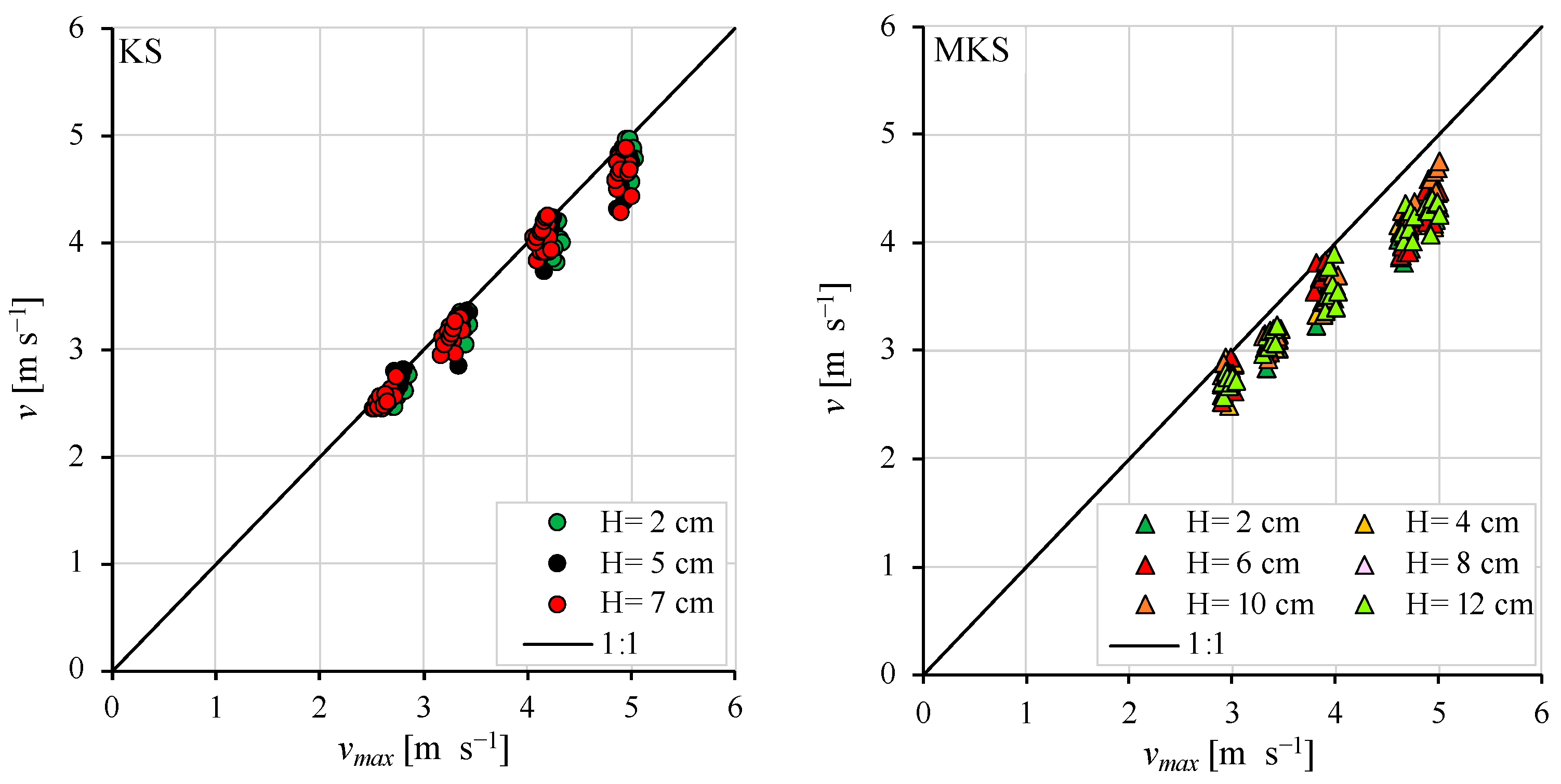
The reliability of the photographic method was checked by comparing the values of the measured v (m s−1) and the theoretical velocity, vmax (m s−1), obtained by Equation (5). Figure 5 shows, for both rainfall simulators, the relationship between v and vmax for different h values. The experimental pairs (vmax, v) are below the 1:1 line, suggesting the reliability of the raindrop velocity measurements obtained by the photographic method for both simulators.
To improve the capability of Equation (1) in estimating rainfall fall velocity for any h value, at first, the VS and aS values were determined using the v and h measurements carried out by Laws [30]. In particular, for a fixed h, the VS and aS values were calculated by minimizing the sum of the squared differences between the v values measured by Laws [30] and those calculated using Equation (1). Figure 6 highlights the dependence of aS VS (Figure 6a) and VS (Figure 6b) with the falling height, h, described by the following equations:
a S = α   h β
V S = γ 1 + δ h ε
where α (cm−1 m−β), β (-), γ (m s−1), δ (mε), and ε (-) are parameters that, considering Laws’ [30] data, assume constant values equal to 11.43 cm−1 m−β, −0.24, 11.50 m s−1, 1.65 mε, and 0.80, respectively.
The accuracy of Equation (8) (R2 = 0.9094) and (9) (R2 = 0.9863) to describe the relationship between aS and VS with the falling height, h, suggest introducing Equations (8) and (9) for estimating VS and aS in Equation (1), and thus the latter can be rewritten as:
v C a l c = 11.50 1 + 1.65 h 0.80 1 e 11.43 h 0.24 D
According to Equation (10), the fall velocity, v, of the simulated raindrop can be calculated by the knowledge of the falling height, h (m), and the raindrop diameter, D (cm).
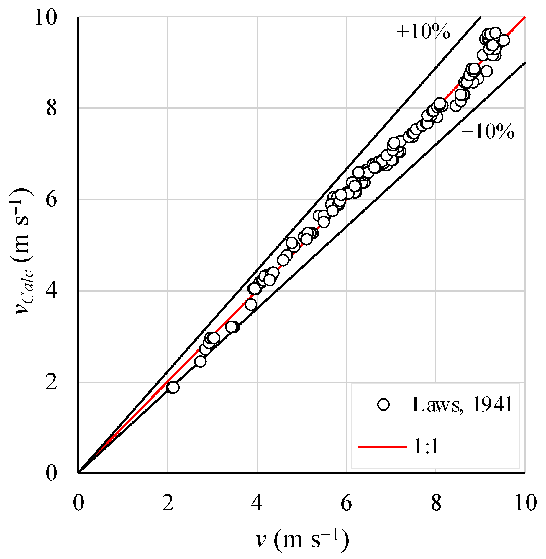
To test the accuracy of Equation (10) in estimating fall velocity, at first the measurements by Laws [30] were considered. Figure 7 shows the comparison between the measured values of v and those calculated by Equation (10). The points corresponding to these pairs are located around the line of perfect agreement (R2 = 0.9994), registering a mean absolute error (MAE) equal to 2.10%, and 98.04% of the measurements are affected by MAE ≤ 10% (Table 1).
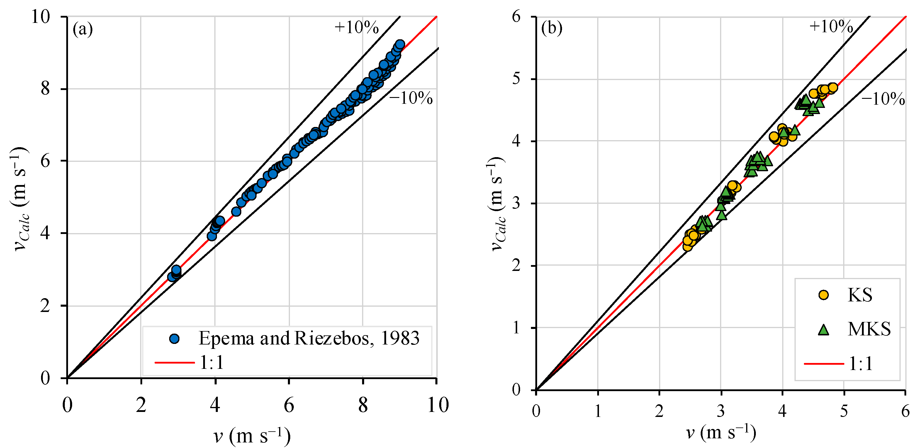
The reliability of Equation (10) was also tested considering the fall velocity measurements carried out by Epema and Riezebos [33] (Figure 8a) and those measured by the investigated simulators, KS and MKS (Figure 8b). The nearness of the points of the pairs (v, vCalc) to the 1:1 line, and the R2 values almost equal to 1 (Table 1), confirm the applicability of Equation (10) to fall velocity estimates, independently of the rainfall simulator considered in the present investigation (Figure 8). Indeed, even if the use of Equation (10) produces slight underestimations of the fall velocity (Table 1), all the measurements are affected by a mean absolute error less than or equal to 10% (Table 1).
The developed tests of Equation (10) support its applicability for calculating the kinetic power and momentum of the simulated rainfall for KS and MKS. Therefore, substituting Equation (10) in Equations (6) and (7), the following relationships were obtained:
P n C a l c = 0.5 m σ t 11.50 1 + 1.65 h 0.80 1 e 11.43 h 0.24 D 2
M C a l c = m σ t 11.50 1 + 1.65 h 0.80 1 e 11.43 h 0.24 D
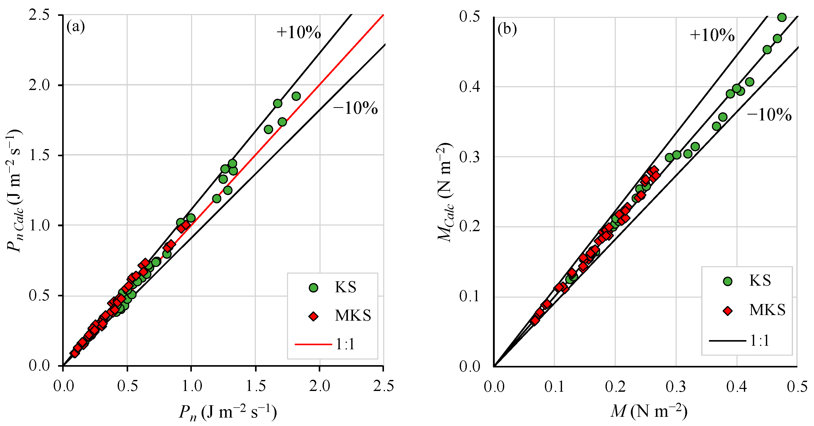
According to Equations (11) and (12), Pn and M per unit area, σ, and time, t, are functions of h, m, and thus of D. Figure 9 shows the comparison between the measured values of Pn and M and those calculated, PnCalc and MCalc, using Equations (11) and (12), both for the Kamphorst simulator and the modified Kamphorst simulator. The closeness of the pairs (Pn, PnCalc) (Figure 9a) and (M, MCalc) to the line of perfect agreement (Figure 9b) confirms the reliability of the proposed relationships to estimate Pn and M. Moreover, as reported in Table 2, better results are obtained for both simulators in the estimation of the rainfall momentum. Indeed, for both simulators, all the rainfall momentum measurements have a mean absolute error less than or equal to 10%. Concerning rainfall kinetic power, the measurements affected by mean absolute errors less than or equal to 10% are less than 82.5% (Table 2).

4. Discussion

For a fixed pressure head and capillary tube diameter, the comparison between the pairs (IS and D) of the KS and those obtained by MKS showed that the increase in the length of the capillary tube results in a significant decrease in the simulated rainfall intensity and, consequently, of the raindrop diameter values (Figure 4). Moreover, concerning the MKS, the use of a longer capillary tube, having the same inner diameter as the KS, allowed the exploration of higher pressure heads, which correspond to lower values of rainfall intensities and as a consequence of the simulated raindrop diameter (Figure 4). In particular, the use of the MKS enabled the simulation of rainfall constituted of small raindrop diameters. Moreover, for both simulators, the increase in IS, due to growth in H, determined a decrease in D because, in a given sampling time, the raindrop formation rate at the outlet of the nozzle increases, and this circumstance produces many drops characterized by low D values.
To characterize the simulators energetically for each considered pressure head, the fall velocity measurements, v (m s−1), were carried out using the photographic technique for h lower than 1.3 m, which was the maximum explorable value for the experimental setup considered in this investigation. Notwithstanding the limits of the mobile phone used in the present investigation, which is why the photographic technique was not considered for the determination of the droplet diameter, the proposed method allowed for accurate measurements of the raindrop fall velocity (Figure 5).
Despite the low values of h considered in the present investigation, the measured v values, which resulted as lower than the theoretical ones obtained by Equation (5), highlighted the influence of air resistance during the drop fall motion. Therefore, in agreement with many authors [3,31,37,38,39,40,41,42,43,44,45,46,47], the measured values of the raindrop falling velocity highlighted the importance of the drop falling height in the v estimate, since h synthesizes the effects of air density and viscosity during the raindrop falling process.
Thus, for simulated precipitation, in which the falling heights are very low (h < 20 m), h is a variable that has to be considered, in addition to D, for computing the raindrop fall velocity. The new proposed empirical relationship (Equation (10)), calibrated using Laws’ [30] measurements, allowed a reliable estimation of the fall velocity, for simulated raindrops having a D ranging from 1 to 6 mm, and h varying from 0.5 to 20 m. The analysis conducted in the present investigation suggested that this result is independent of the considered rainfall simulator (Figure 7 and Figure 8). In other words, for any drip-type rainfall simulator, the use of Equation (10) yields accurate v estimates when both the raindrop diameter and its falling height are known. The information relative to the raindrop diameter and velocity for different falling height values allowed for characterizing KS and MKS both in terms of kinetic power, Pn, and momentum, M.
The comparison between the measured values of Pn and M and those estimated by Equations (11) and (12), respectively, suggest that for h < 1.3 m, the knowledge of both the mass, and thus the raindrop diameter, and the raindrop falling height yielded accurate estimations of the kinetic power and momentum of the rainfall produced by the two simulators in the present investigation. In other words, awareness of the geometric characteristics of the capillary tube, the pressure head, and the falling height values are fundamental for having a complete characterization of the rainfall simulator, because these variables allow the determination of IS, Pn, and M.
In addition to these results, the use of a capillary tube longer than the KS one allowed for exploring values of rainfall intensity, raindrop diameter (Figure 4), and thus of Pn and M (Figure 9) that are lower than those obtained using the Kamphorst simulator in its original form. These findings could be interesting for the realization of a new rainfall simulator with different capillary tubes that can be changed to simulate a specific rainfall.

Operative Instructions

From an operative point of view, the analyses conducted in this investigation using the KS and the MKS simulators gave useful information on the characterization of a drip-type rainfall simulator.
In general, for each test condition and geometric characteristic of the capillary tube, the rainfall intensity is easily measured knowing the water volume that flows out in each sampling time. The weighing of the water volume corresponding to a fixed number of drops flowing out by the selected capillary tube allows for determining the mass and thus the mean raindrop diameter value.
The use of Equation (10), proposed and verified in this investigation using differing fall velocity measurements available in the literature, allows reliable estimations of v by the knowledge of h, set by the operator, and D, obtained by the previously described procedure. Therefore, the measurement of these variables enables the operator to calculate the kinetic power and momentum of simulated precipitations produced by drip-type rainfall simulators.
In other words, to completely characterize a drip-type rainfall simulator, it is enough to fix the operating conditions (pressure head, water temperature) and know the capillary tube features (diameter, length).

5. Conclusions

Rainfall simulators, providing controlled conditions for investigating hydrological and erosive processes, are valuable tools for scientific research into soil erosion processes.
The aim of this investigation was to give instructions for the characterization of two drip rainfall simulators, named KS (Kamphorst simulator) and MKS (modified Kamphorst simulator), by coupling the weighing and photographic techniques for the measurement of the raindrop mass, diameter, and fall velocity.
In particular, the present study revealed that the simulated rainfall intensity is the only factor affecting the diameter of raindrops, which has a decreasing trend with IS, due to an increase in the outflow velocity. Moreover, by fixing the capillary tube’s inner diameter, the increase in its length (MKS) allows for reproducing rainfall having lower intensity and thus smaller raindrops than those produced by KS.
Concerning raindrop fall velocity, using Laws [30] measurements, a new empirical relationship to estimate raindrop fall velocity is proposed, according to which v is a function of the falling height and the raindrop diameter. The reliability of the proposed empirical equation was positively tested using fall velocity measurements of the present investigation and those available in the literature. Moreover, the measured Pn and M values of the present investigation allowed for suggesting that, for h < 1.3 m, knowing both the mass, and thus the raindrop diameter, and the raindrop falling height, enables accurate estimates of both the rainfall kinetic power and momentum produced by the drip-type rainfall simulators. In other words, the results of the present investigation find an operative field in the study of hydrological and soil erosion processes, because the knowledge of both the operating conditions (pressure head, water temperature) and the diameter and length of the capillary tubes allows for completely characterizing a drip-type rainfall simulator.
The advantage of having a rainfall simulator with known characteristics and thus in controlled conditions, which are generally not achievable with natural rainfall, enables a deeper understanding of the dynamics of several sub-processes involved in erosion phenomena, such as rain detachment or, for example, the relationship between interrill erosion and the energy characteristics of the precipitation at the plot scale. Future investigations could be aimed at verifying the reliability of the proposed empirical relationships considering a wider range of falling heights and other rainfall simulators. Moreover, the use of a disdrometer or the application of photographic techniques with the use of a high-speed camera will enable comparison with the raindrop size and the raindrop fall velocity values obtained in this investigation.

Author Contributions

Conceptualization, M.A.S., F.G.C., R.C., and V.F.; methodology, M.A.S., F.G.C., R.C., and V.F.; validation, M.A.S., F.G.C., R.C., and V.F.; formal analysis, M.A.S., F.G.C., R.C., and V.F.; writing—original draft preparation, M.A.S., F.G.C., R.C., and V.F.; writing—review and editing, M.A.S., F.G.C., and V.F.; supervision, F.G.C. and V.F.; funding acquisition, F.G.C. All authors have read and agreed to the published version of the manuscript.

Funding

This research was funded by the “SiciliAn MicronanOTecH Research and Innovation CEnter “SAMOTHRACE” (MUR, PNRR-M4C2, ECS_00000022), spoke 3—Università degli Studi di Palermo “S2-COMMs—Micro and Nanotechnologies for Smart & Sustainable Communities”.

Data Availability Statement

The data presented in this study are available on request from the corresponding author.

Conflicts of Interest

The authors declare no conflicts of interest.

Abbreviations

AbbreviationDescriptionUnits
aSParameter of Equation (1) depending on raindrop falling heightcm−1
dCapillary tube inner diameter m
DRaindrop equivalent diameter m
gGravity acceleration m s−2
hRaindrop falling height m
HPressure head m
ISRainfall intensity mm h−1
luCapillary tube length m
mWeight of the water volumekg
mSDMean mass of a single raindropkg
MRainfall momentum per unit time and area N m−2
MCalcRainfall momentum per unit time and area calculated by Equation (12) N m−2
nDNumber of drops -
PnRainfall kinetic power per unit time and areaJ m−2 s−1
PnCalcRainfall kinetic power per unit time and area calculated by Equation (11) J m−2 s−1
R2Coefficient of determination -
tSampling times
TWater temperature°C
vRaindrop fall velocity m s−1
vCalcRaindrop fall velocity calculated by Equation (10)m s−1
vmaxMaximum velocity of a raindrop falling freely in a vacuum, starting from restm s−1
vtRaindrop terminal velocity m s−1
VSParameter of Equation (1) depending on raindrop falling heightm s−1
VSDMean volume of a single raindrop m3
αParameter of Equation (8)cm−1 m−β
βParameter of Equation (8)-
γParameter of Equation (9)m s−1
δParameter of Equation (9)mε
εParameter of Equation (9)-
ρWater density kg m−3
σSurface area assigned to a single capillary tube m2

Acronyms

AcronymMeaning
DSDDrop size distribution
FPSFrames per second
KSKamphorst rainfall simulator
LEDLight-emitting diode
MAEMean absolute error
MKSModified Kamphorst rainfall simulator
USLEUniversal Soil Loss Equation

References

  1. Arunrat, N.; Sereenonchai, S.; Kongsurakan, P.; Hatano, R. Assessing soil organic carbon, soil nutrients and soil erodibility under terraced paddy fields and upland rice in Northern Thailand. Agronomy 2022, 12, 537. [Google Scholar] [CrossRef]
  2. Zhao, L.; Zhang, Z.; Dong, F.; Fu, Y.; Hou, L.; Liu, J.; Wang, Y. Research on the Features of Rainfall Regime and Its Influence on Surface Runoff and Soil Erosion in the Small Watershed, the Lower Yellow River. Water 2023, 15, 2651. [Google Scholar] [CrossRef]
  3. Leone, A.; Pica, M. Caratteristiche dinamiche e simulazione delle piogge. Parte prima: Fondamenti teorici. Riv. Ing. Agrar. 1993, 3, 167–175. [Google Scholar]
  4. Imeson, A.C. A simple field-portable rainfall simulator for difficult terrain. Earth Surf. Process. 1977, 2, 431–436. [Google Scholar] [CrossRef]
  5. Luk, S.H. Effect of antecedent soil moisture content on rainwash erosion. Catena 1985, 12, 129–139. [Google Scholar] [CrossRef]
  6. Roth, C.H.; Meyer, B.; Frede, H.G. A portable rainfall simulator for studying factors affecting runoff, infiltration and soil loss. Catena 1985, 12, 79–85. [Google Scholar] [CrossRef]
  7. Kamphorst, A. A small rainfall simulator for the determination of soil erodibility. Neth. J. Agric. Sci. 1987, 35, 407–415. [Google Scholar] [CrossRef]
  8. Poesen, J.; Ingelmo-Sanchez, F.; Mucher, H. The hydrological response of soil surfaces to rainfall as affected by cover and position of rock fragments in the top layer. Earth Surf. Process. Landf. 1990, 15, 653–671. [Google Scholar] [CrossRef]
  9. Cerdà, A.; Ibáñez, S.; Calvo, A. Design and operation of a small and portable rainfall simulator for rugged terrain. Soil Technol. 1997, 11, 163–170. [Google Scholar] [CrossRef]
  10. Torri, D.; Regüés, D.; Pellegrini, S.; Bazzoffi, P. Within-storm soil surface dynamics and erosive effects of rainstorms. Catena 1999, 38, 131–150. [Google Scholar] [CrossRef]
  11. Battany, M.C.; Grismer, M.E. Development of a portable field rainfall simulator for use in hillside vineyard runoff and erosion studies. Hydrol. Process. 2000, 14, 1119–1129. [Google Scholar] [CrossRef]
  12. Regmi, T.P.; Thompson, A.L. Rainfall simulator for laboratory studies. Appl. Eng. Agric. 2000, 16, 641–647. [Google Scholar] [CrossRef]
  13. Loch, R.J.; Robotham, B.G.; Zeller, L.; Masterman, N.; Orange, D.N.; Bridge, B.J.; Sheridan, G.J.; Bourke, J.J. A multi-purpose rainfall simulator for field infiltration and erosion studies. Soil Res. 2001, 39, 599–610. [Google Scholar] [CrossRef]
  14. Humphry, J.B.; Daniel, T.C.; Edwards, D.R.; Sharpley, A.N. A portable rainfall simulator for plot–scale runoff studies. Appl. Eng. Agric. 2002, 18, 199. [Google Scholar] [CrossRef]
  15. Regüés, D.; Gallart, F. Seasonal patterns of runoff and erosion responses to simulated rainfall in a badland area in Mediterranean mountain conditions (Vallcebre, southeastern Pyrenees). Earth Surf. Process. Landf. 2004, 29, 755–767. [Google Scholar] [CrossRef]
  16. Birt, L.N.; Persyn, R.A.; Smith, P.K. Evaluation of an indoor nozzle-type rainfall simulator. Appl. Eng. Agric. 2007, 23, 283–287. [Google Scholar] [CrossRef]
  17. Clarke, M.A.; Walsh, R.P. A portable rainfall simulator for field assessment of splash and slopewash in remote locations. Earth Surf. Process. Landf. 2007, 32, 2052–2069. [Google Scholar] [CrossRef]
  18. Alves Sobrinho, T.; Gómez-Macpherson, H.; Gómez, J.A. A portable integrated rainfall and overland flow simulator. Soil Use Manag. 2008, 24, 163–170. [Google Scholar] [CrossRef]
  19. Nadal-Romero, E.; Regüés, D. Detachment and infiltration variations as consequence of regolith development in a Pyrenean badland system. Earth Surf. Process. Landf. 2009, 34, 824–838. [Google Scholar] [CrossRef]
  20. Abudi, I.; Carmi, G.; Berliner, P. Rainfall simulator for field runoff studies. J. Hydrol. 2012, 454, 76–81. [Google Scholar] [CrossRef]
  21. Iserloh, T.; Ries, J.B.; Arnáez, J.; Boix-Fayos, C.; Butzen, V.; Cerdà, A.; Echeverría, M.T.; Fernández-Gálvez, J.; Fister, W.; Geißler, C.; et al. European small portable rainfall simulators: A comparison of rainfall characteristics. Catena 2013, 110, 100–112. [Google Scholar] [CrossRef]
  22. Lascelles, B.; Favis-Mortlock, D.T.; Parsons, A.J.; Guerra, A.J.T. Spatial and temporal variation in two rainfall simulators: Implications for spatially explicit rainfall simulation experiments. Earth Surf. Process. Landf. 2000, 25, 709–721. [Google Scholar] [CrossRef]
  23. Boulal, H.; Gómez-Macpherson, H.; Gómez, J.A.; Mateos, L. Effect of soil management and traffic on soil erosion in irrigated annual crops. Soil Tillage Res. 2011, 115, 62–70. [Google Scholar] [CrossRef]
  24. Ries, J.B.; Iserloh, T.; Seeger, M.; Gabriels, D. Rainfall simulations-constraints, needs and challenges for a future use in soil erosion research. Z. Für Geomorphol. 2013, 57 (Suppl. S1), 1–10. [Google Scholar] [CrossRef]
  25. Eijkelkamp. Rainfall Simulator—Operating Instructions, M-0906E. 2022. Available online: https://www.royaleijkelkamp.com/media/1awdmlno/m-0906e-rainfall-simulator.pdf (accessed on 13 June 2024).
  26. Bagarello, V.; Baiamonte, G.; Ferro, V.; Giordano, G. Contributo alla valutazione dei fattori elementari dell’erosione negli studi a scala di bacino. Quad. Idronomia Mont. 1996, 15, 47–82. [Google Scholar]
  27. Serio, M.A.; Carollo, F.G.; Ferro, V. Raindrop size distribution and terminal velocity for rainfall erosivity studies. A review. J. Hydrol. 2019, 576, 210–228. [Google Scholar] [CrossRef]
  28. Beard, K.V. Terminal velocity and shape of cloud and precipitation drops aloft. J. Atmos. Sci. 1976, 33, 851–864. [Google Scholar] [CrossRef]
  29. Jayawardena, A.W.; Rezaur, R.B. Drop size distribution and kinetic energy load of rainstorms in Hong Kong. Hydrol. Process. 2000, 14, 1069–1082. [Google Scholar] [CrossRef]
  30. Laws, J.O. Measurements of the fall-velocity of water-drops and raindrops. Eos Trans. Am. Geophys. Union 1941, 22, 709–721. [Google Scholar] [CrossRef]
  31. Gunn, R.; Kinzer, G.D. The terminal velocity of fall for water droplets in stagnant air. J. Atmos. Sci. 1949, 6, 243–248. [Google Scholar] [CrossRef]
  32. Blanchard, D.C. The behavior of water drops at terminal velocity in air. Eos Trans. Am. Geophys. Union 1950, 31, 836–842. [Google Scholar] [CrossRef]
  33. Epema, G.F.; Riezebos, H.T. Fall velocity of waterdrops at different heights as a factor influencing erosivity of simulated rain. Catena Supp. 1983, 4, 1–17. [Google Scholar]
  34. Ries, J.B.; Seeger, M.; Iserloh, T.; Wistorf, S.; Fister, W. Calibration of simulated rainfall characteristics for the study of soil erosion on agricultural land. Soil Tillage Res. 2009, 106, 109–116. [Google Scholar] [CrossRef]
  35. Ries, J.B.; Langer, M. Runoff generation on abandoned fields in the Central Ebro Basin. Results from rainfall simulation experiments. Cuad. Investig. Geográf. Geogr. Res. Lett. 2001, 27, 61–78. [Google Scholar] [CrossRef]
  36. Seeger, M. Uncertainty of factors determining runoff and erosion processes as quantified by rainfall simulations. Catena 2007, 71, 56–67. [Google Scholar] [CrossRef]
  37. Carollo, F.G.; Caruso, R.; Palmeri, V.; Serio, M.A. Rainfall energy characteristics of a Kamphorst’s simulator. Quad. Idronomia Mont. 2024, 37, 367–374. [Google Scholar]
  38. Davies, C.N. Unpublished Ministry of Supply Reports Quoted by Sutton in Air Ministry Report, M.R.P. No. 40. 1942.
  39. Spilhaus, A.F. Raindrop size, shape and falling speed. J. Atmos. Sci. 1948, 5, 108–110. [Google Scholar] [CrossRef]
  40. Best, A.C. Empirical formulae for the terminal velocity of water drops falling through the atmosphere. Q. J. R. Meteorol. Soc. 1950, 76, 302–311. [Google Scholar] [CrossRef]
  41. Kessler, E.; Wilk, K.E. Radar Measurement of Precipitation for Hydrological Purposes; World Meteorological Organization: Geneva, Switzerland, 1968. [Google Scholar]
  42. Liu, J.Y.; Orville, H.D. Numerical modeling of precipitation and cloud shadow effects on mountain-induced cumuli. J. Atmos. Sci. 1969, 26, 1283–1298. [Google Scholar] [CrossRef]
  43. Sekhon, R.S.; Srivastava, R.C. Doppler radar observations of drop-size distributions in a thunderstorm. J. Atmos. Sci. 1971, 28, 983–994. [Google Scholar] [CrossRef]
  44. Atlas, D.; Ulbrich, C.W. Path-and area-integrated rainfall measurement by microwave attenuation in the 1–3 cm band. J. Appl. Meteorol. Climatol. 1977, 16, 1322–1331. [Google Scholar] [CrossRef]
  45. Uplinger, W.G. A new formula for raindrop terminal velocity. In Proceedings of the 20th Conference on Radar Meteorology, Boston, MA, USA, 30 November–3 December 1981; pp. 389–391. [Google Scholar]
  46. Grosh, R.C. Weighted fall speed parameters. In Proceedings of the 26th International Conference on Radar Meteorology, Boston, MA, USA, 24–28 May 1993; pp. 607–610. [Google Scholar]
  47. Ferro, V. Tecniche di misura e monitoraggio dei processi erosivi. Quad. Idronomia Mont. 2001, 21, 63–128. [Google Scholar]
  48. Assouline, S.; El Idrissi, A.; Persoons, E. Modelling the physical characteristics of simulated rainfall: A comparison with natural rainfall. J. Hydrol. 1997, 196, 336–347. [Google Scholar] [CrossRef]
  49. Wolfs, J.L. Contribution à L’étude de L’erosion par Simulation de Pluie. MSc Thesis, University Catholique de Louvain-La-Nueve, Louvain-la-Neuve, Belgium, 1981. [Google Scholar]
  50. Pruppacher, H.R.; Pitter, R.L. A semi-empirical determination of the shape of cloud and rain drops. J. Atmos. Sci. 1971, 28, 86–94. [Google Scholar] [CrossRef]
  51. Serio, M.A.; Carollo, F.G.; Ferro, V. A method for evaluating rainfall kinetic power by a characteristic drop diameter. J. Hydrol. 2019, 577, 123996. [Google Scholar] [CrossRef]
  52. Carollo, F.G.; Ferro, V.; Serio, M.A. Reliability of rainfall kinetic power–intensity relationships. Hydrol. Process. 2017, 31, 1293–1300. [Google Scholar] [CrossRef]
  53. Carollo, F.G.; Ferro, V.; Serio, M.A. Predicting rainfall erosivity by momentum and kinetic energy in Mediterranean environment. J. Hydrol. 2018, 560, 173–183. [Google Scholar] [CrossRef]
  54. Carollo, F.G.; Serio, M.A.; Ferro, V.; Cerdà, A. Characterizing rainfall erosivity by kinetic power-Median volume diameter relationship. Catena 2018, 165, 12–21. [Google Scholar] [CrossRef]
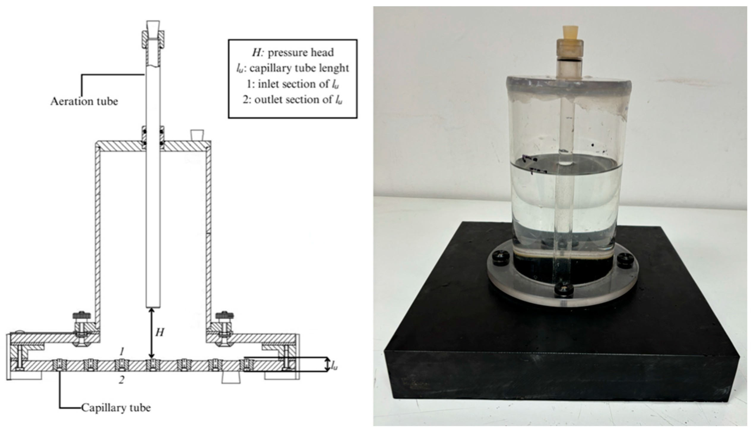
Figure 1. Vertical cross-section and view of Kamphorst rainfall simulator.
Water 16 02100 g001
Figure 2. Scheme of the experimental layout.
Water 16 02100 g002
Figure 3. View of the metal capillary tube with a length (lu) of 28 mm and inner diameter (d) of 0.6 mm made by Benecreat.
Water 16 02100 g003
Figure 4. Relationship between D and IS for different H values for the KS and MKS.
Water 16 02100 g004
Figure 5. Comparison between the values of fall velocity calculated by Equation (5), vmax, and those measured, v, for different H values using KS and MKS.
Water 16 02100 g005
Figure 6. Relationship between h and aS (a) and VS (b) obtained by Laws’ [30] data.
Water 16 02100 g006
Figure 7. Comparison between the values of fall velocity calculated by Equation (10), vcalc, and those measured, v, by Laws [30].
Water 16 02100 g007
Figure 8. Comparison between the values of fall velocity calculated by Equation (10), vcalc, those measured, v, by Epema and Riezebos [33] (a), and of the present investigation (KS and MKS) (b).
Water 16 02100 g008
Figure 9. Comparison between the measured values of Pn and M of the present investigation and those estimated by Equations (10) and (11), respectively.
Water 16 02100 g009
Table 1. Reliability of Equation (10) for estimating fall velocity.
Laws [30]Epema and Riezebos [33]KSMKS
Mean relative error [%]0.21−0.32−0.58−1.73
Mean absolute error [%]2.101.782.433.02
Measurements with absolute error ≤ 10% [%]98.04100.00100.00100.00
Coefficient of determination [R2]0.99940.99970.99930.9990
Table 2. Reliability of Equations (10) and (11) for estimating Pn and M.
KSMKS
Pn
[J m−2 s−1]
M
[N m−2]
Pn
[J m−2 s−1]
M
[N m−2]
Mean relative error [%]1.210.563.591.73
Mean absolute error [%]4.952.476.133.02
Measurements with absolute errors ≤ 10% [%]82.50100.0080.00100.00
Disclaimer/Publisher’s Note: The statements, opinions and data contained in all publications are solely those of the individual author(s) and contributor(s) and not of MDPI and/or the editor(s). MDPI and/or the editor(s) disclaim responsibility for any injury to people or property resulting from any ideas, methods, instructions or products referred to in the content.