
Effect of Flow Interference between Cylinders Subjected to a Cross Flow over a Cluster of Three Equally Spaced Cylinders

Abstract
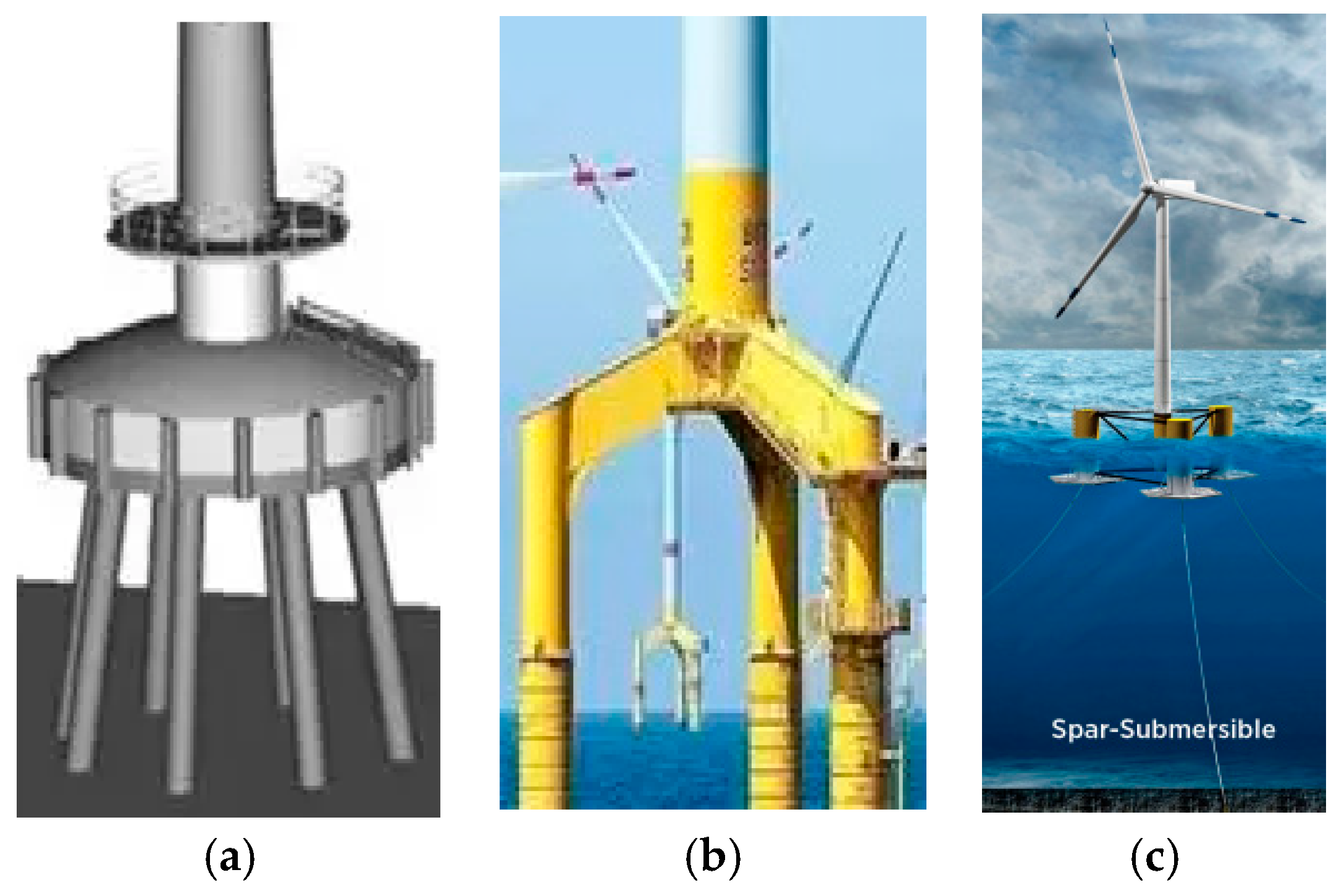
:1. Introduction
2. Numerical Simulation Method and Validity Checking
2.1. Governing Equation
2.2. Turbulence Model and Its Selection for Numerical Simulation
2.2.1. Three Turbulence Models Selected
- (1)
- Realizablek-ε two-equation model:
- (2)
- Two-equation model SSTk-ω considering shear rating [18]:
- (3)
- Three-equation model k-kl-ω [19]:
2.2.2. Comparison between Simulation Results of Different Turbulence Models
- (1)
- Mesh Generation and Time Step
- (2)
- Comparison of simulation results among different turbulence models
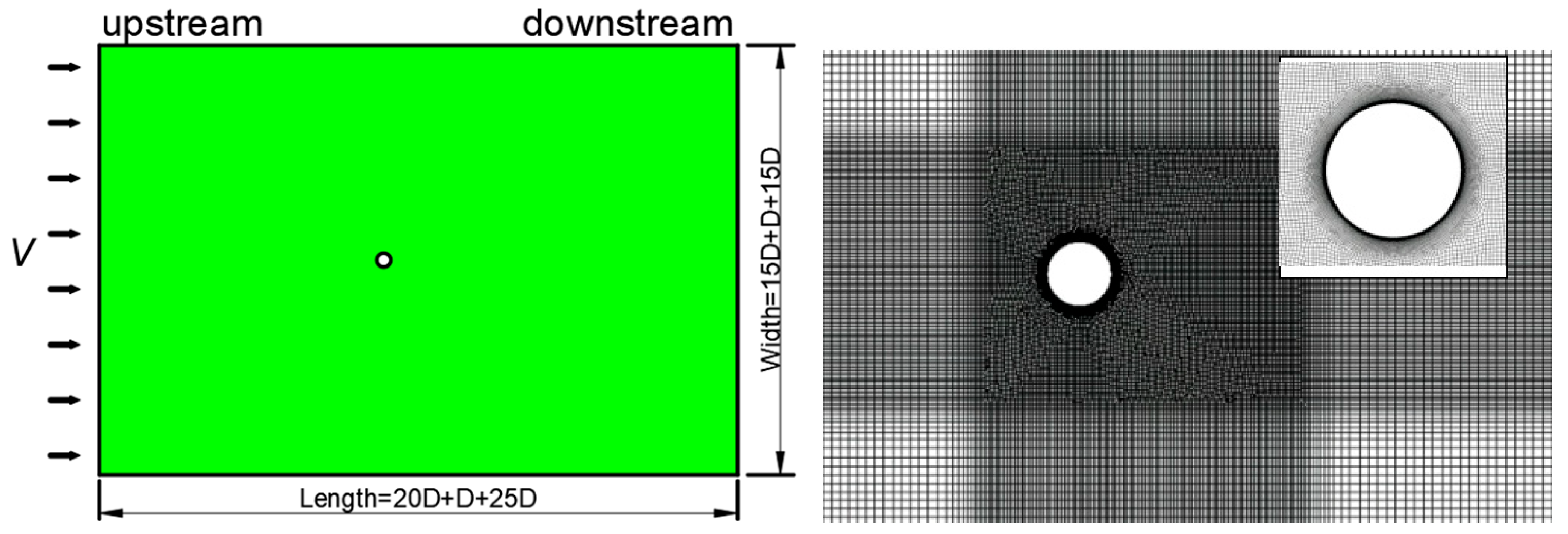
2.3. The Grid and Its Validity Checking
3. Simulation Results
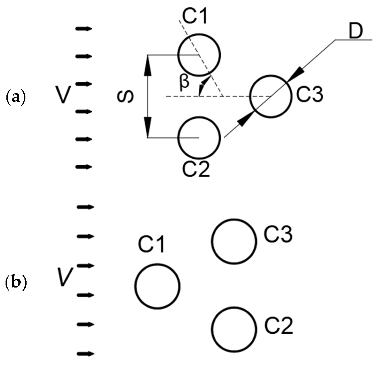
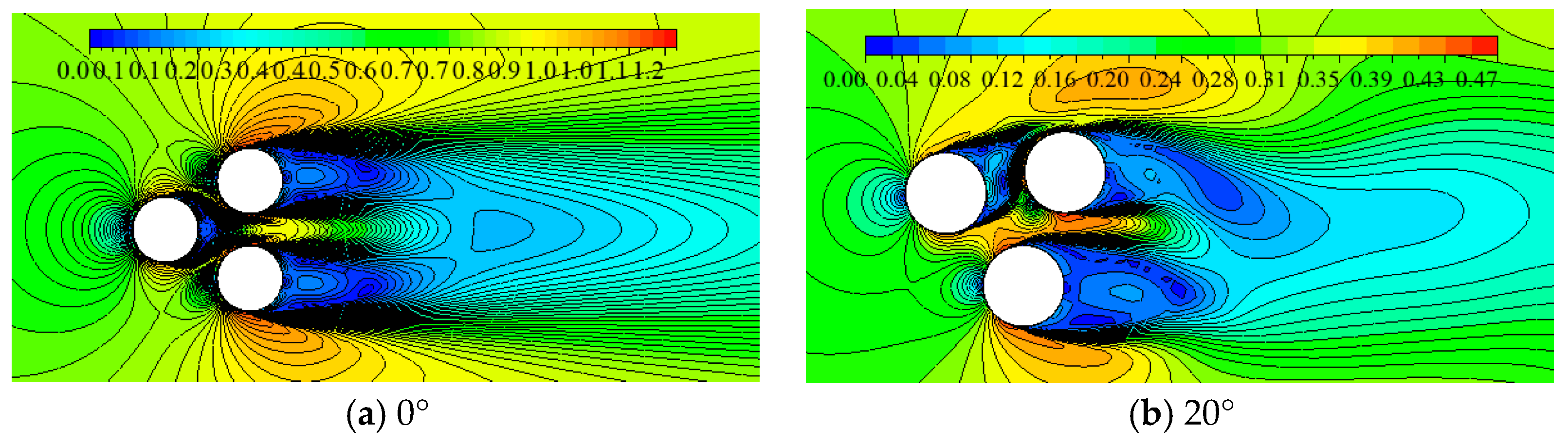
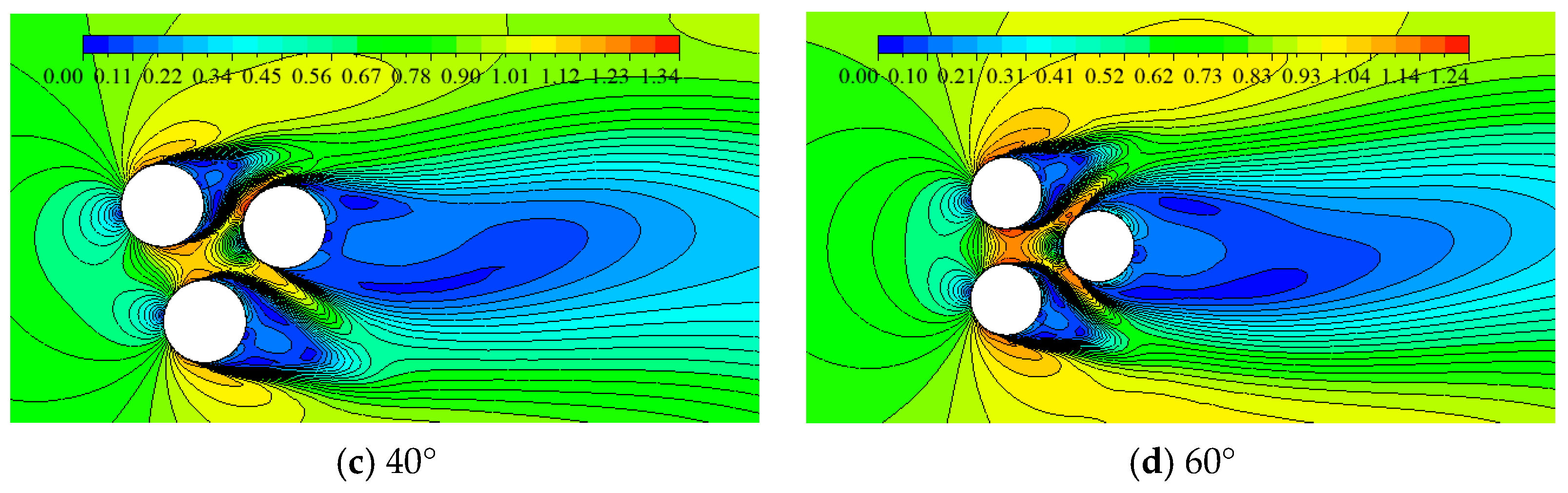
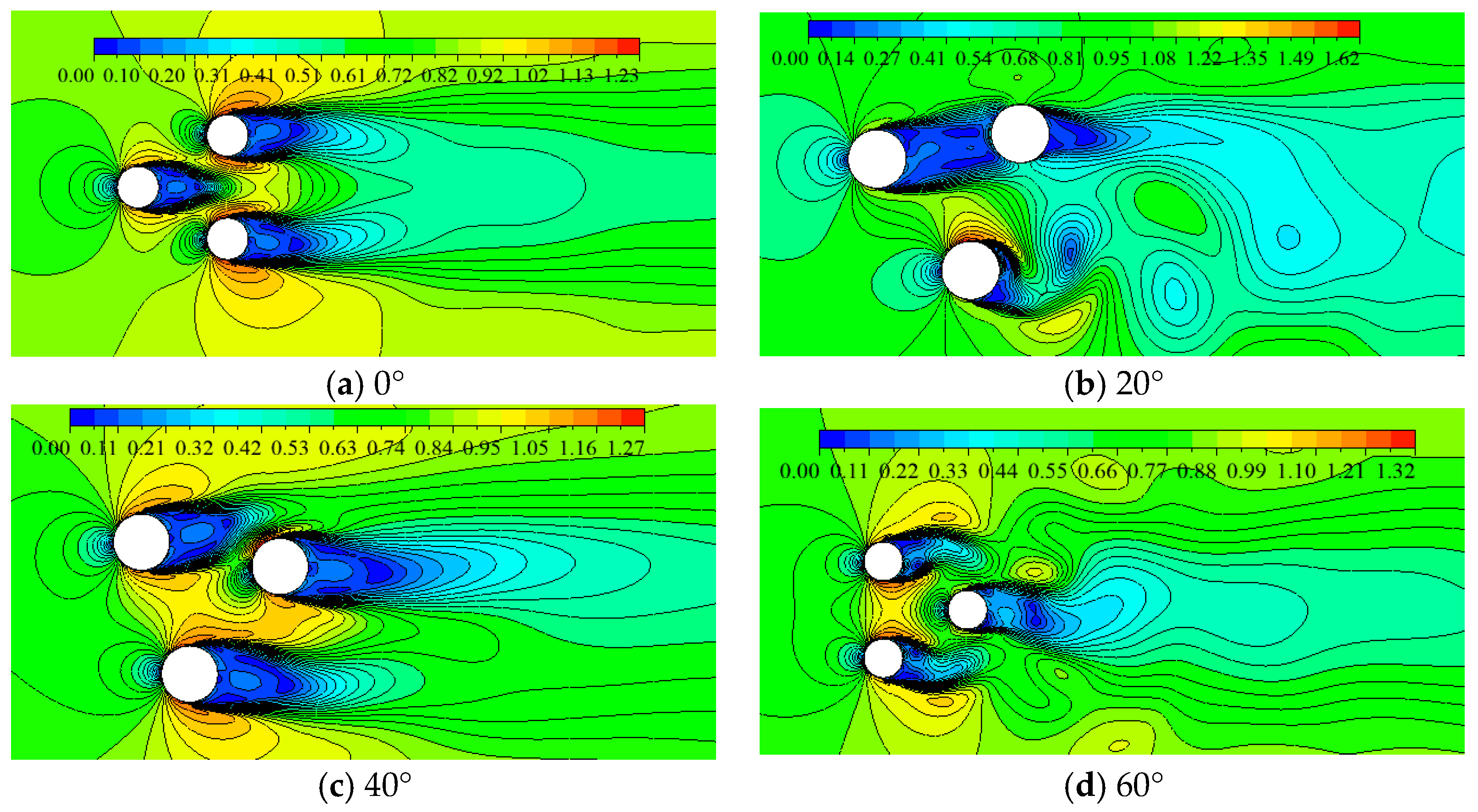
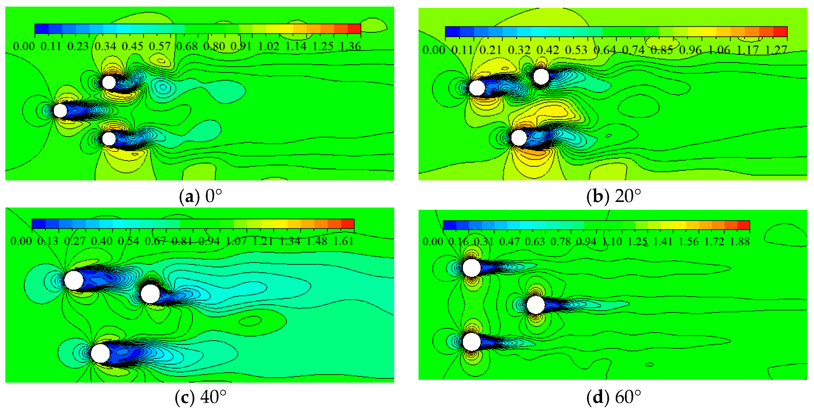
3.1. Flow Interference Pattern Characteristics among Cylinders
3.1.1. Effect of Spacing Ratio S/D on the Flow Pattern
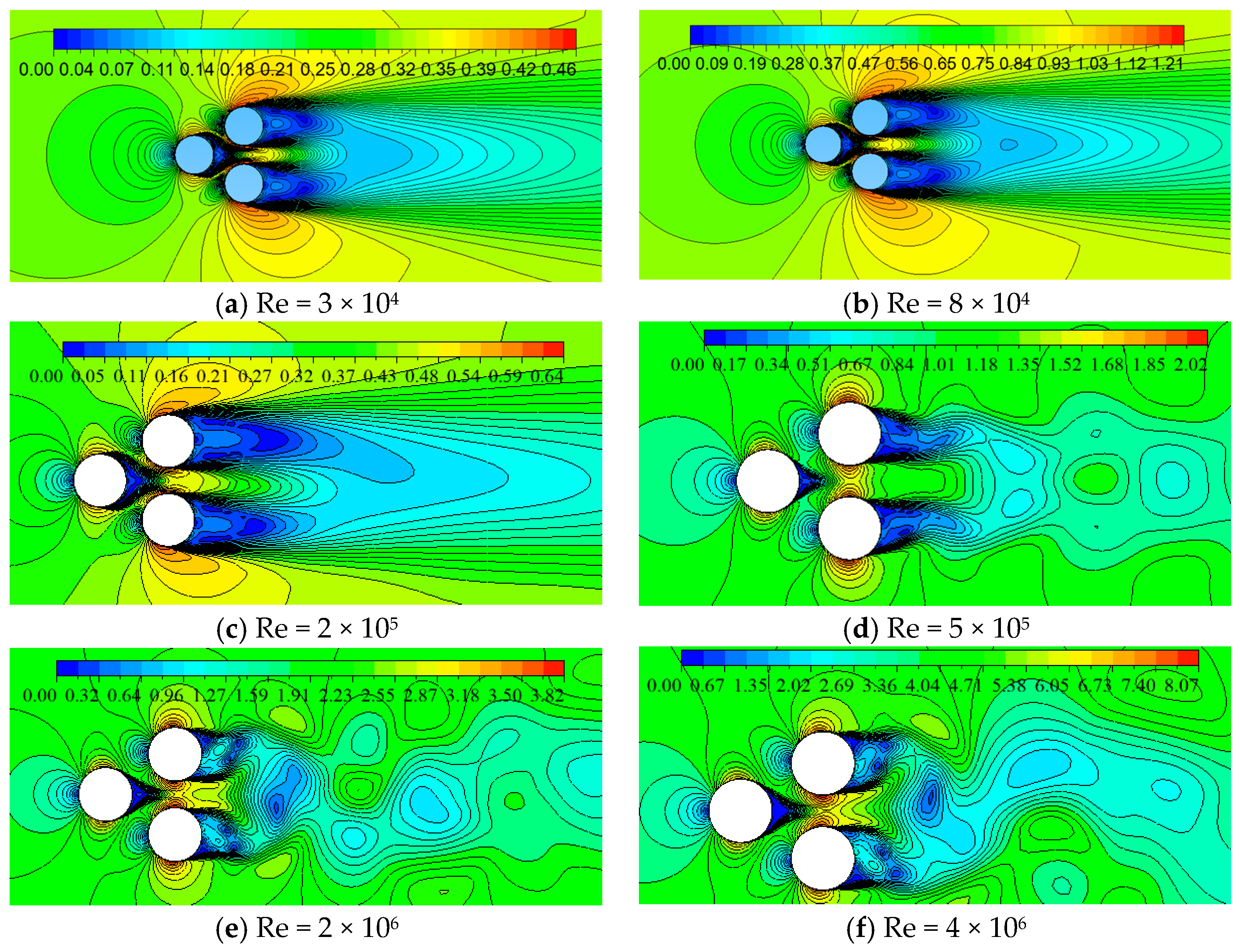
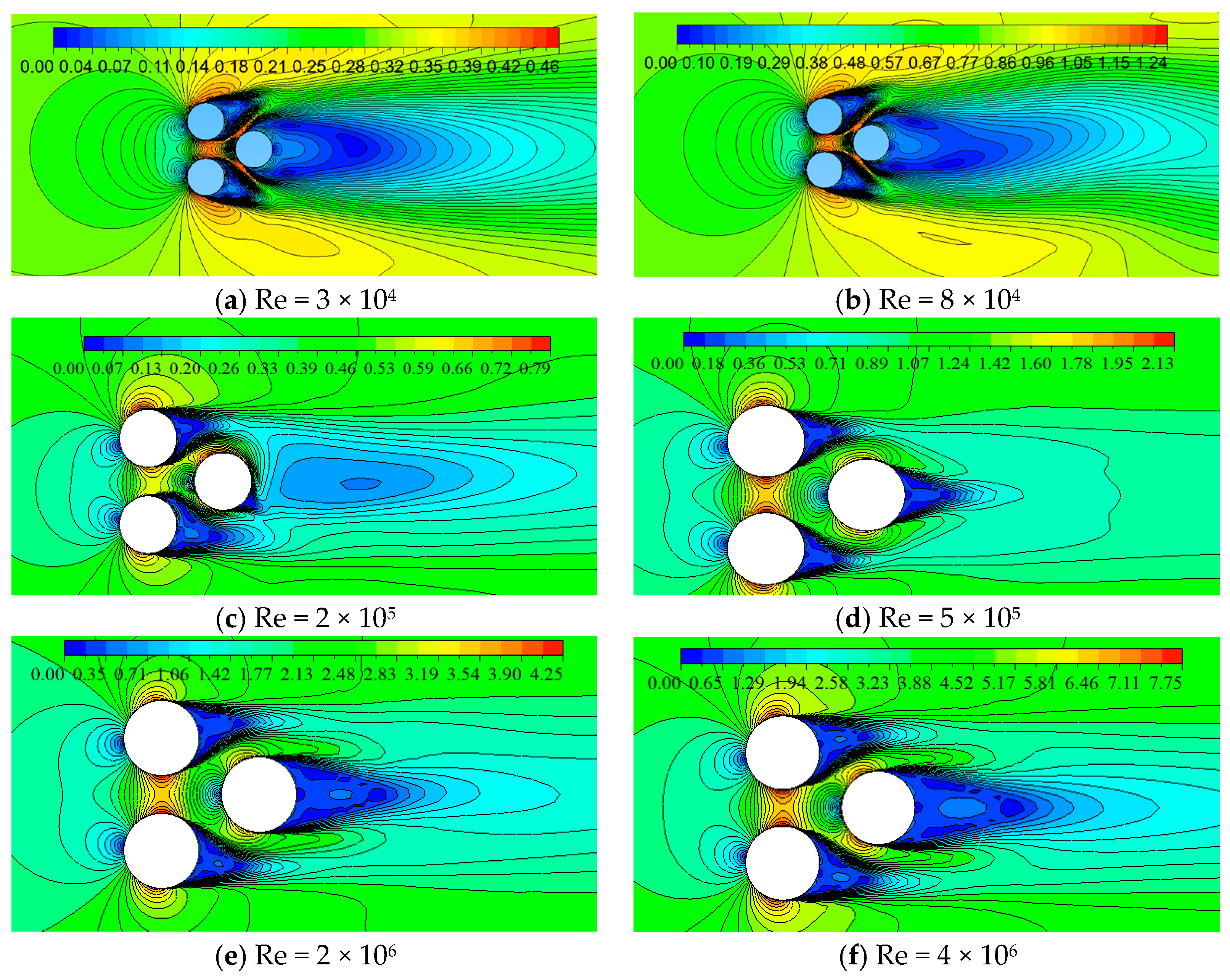
3.1.2. Effect of Reynolds Number
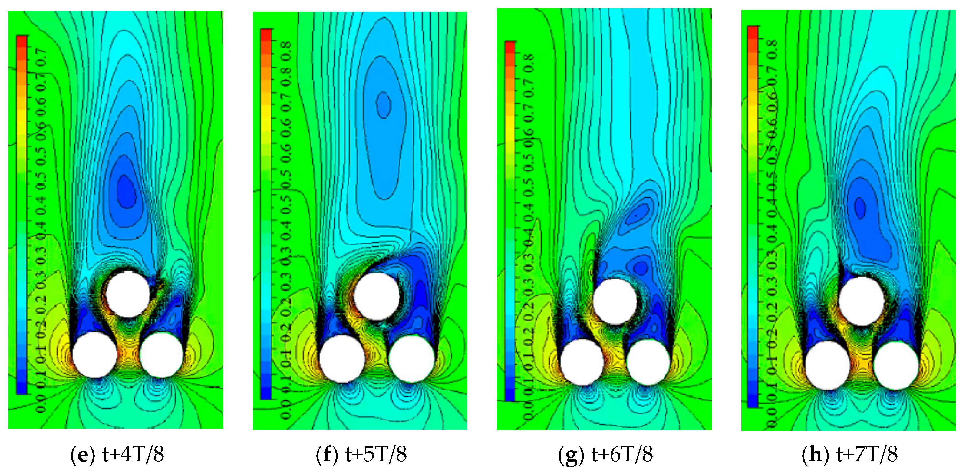
3.1.3. Characteristics of Periodic Flow Regime of the Wake Region Past Three Cylinders—Verification of Three-Dimensional Flow Field
Evolution Process of the Periodic Flow Regime of the Wake Region
3.2. Characteristics of Force Parameters
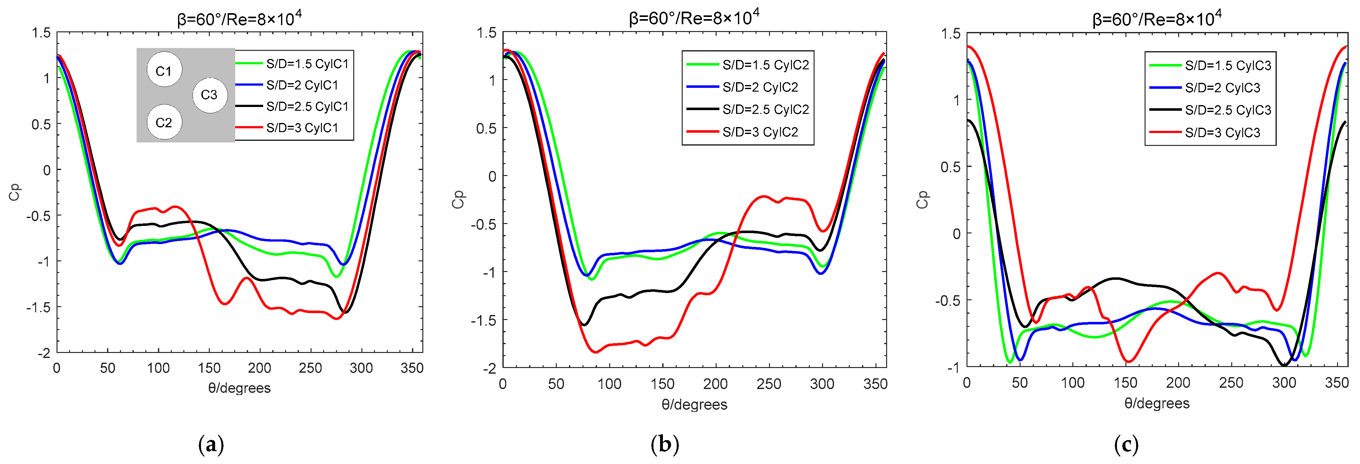
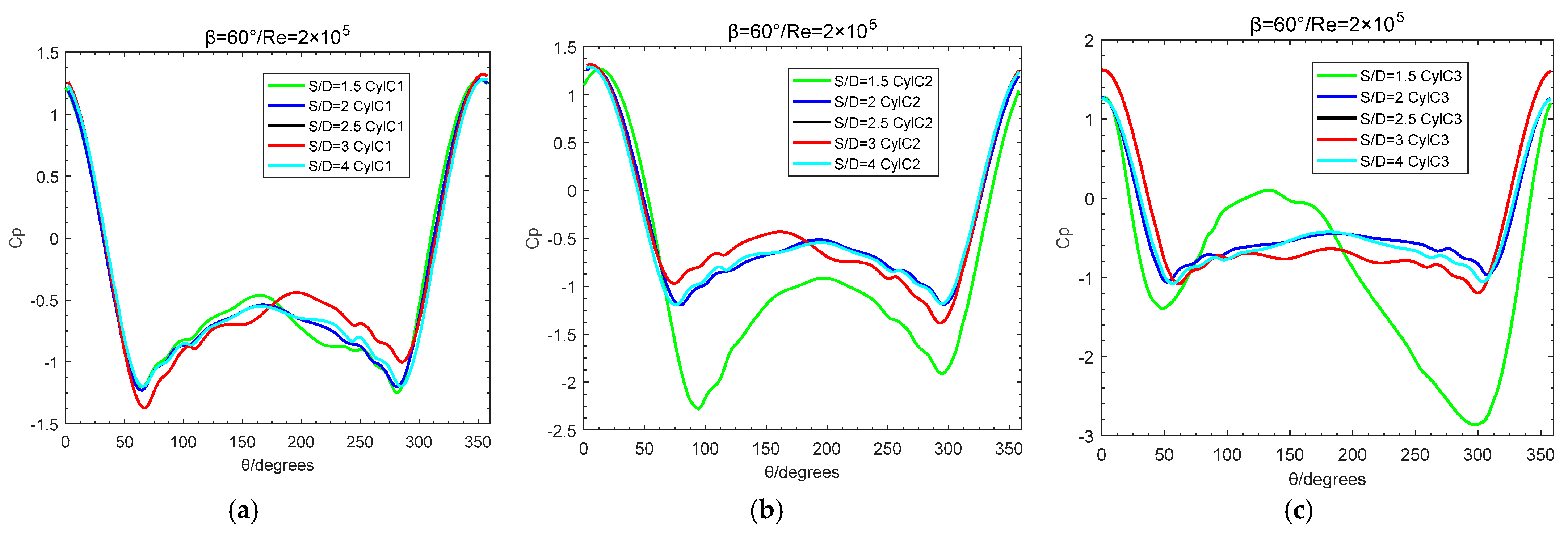
3.2.1. Pressure Coefficient Distributions around Cylinders
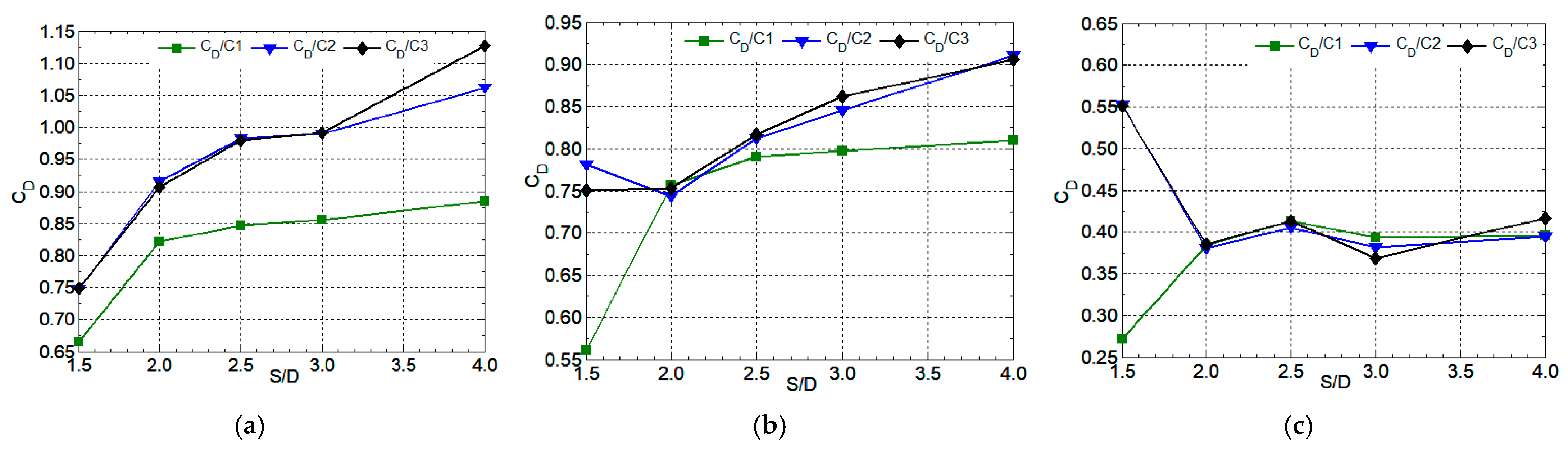
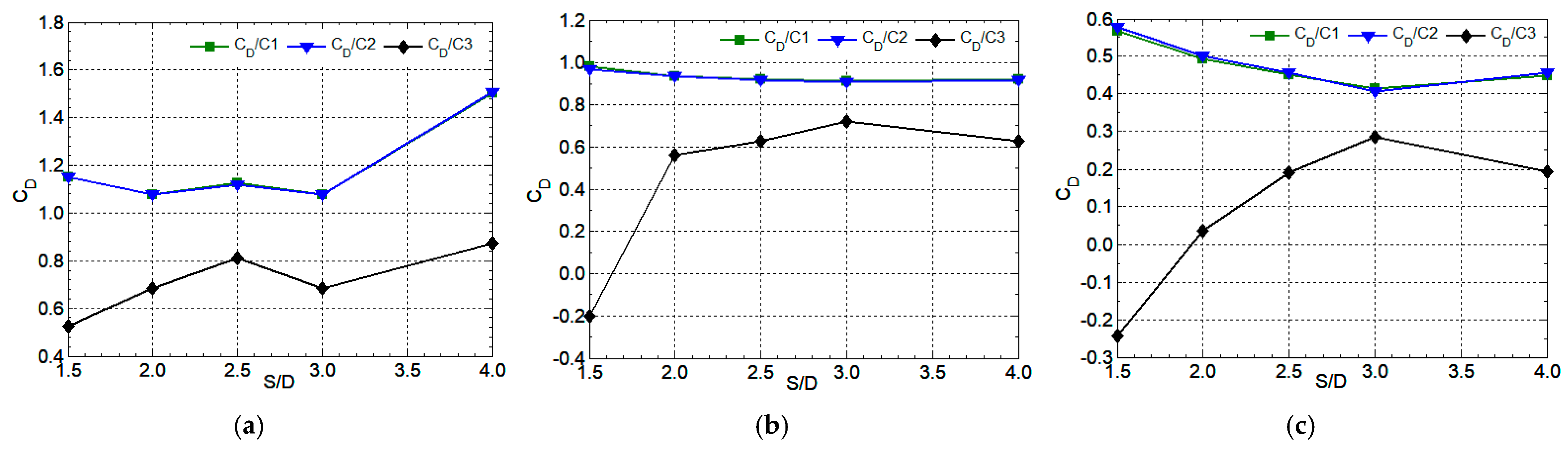
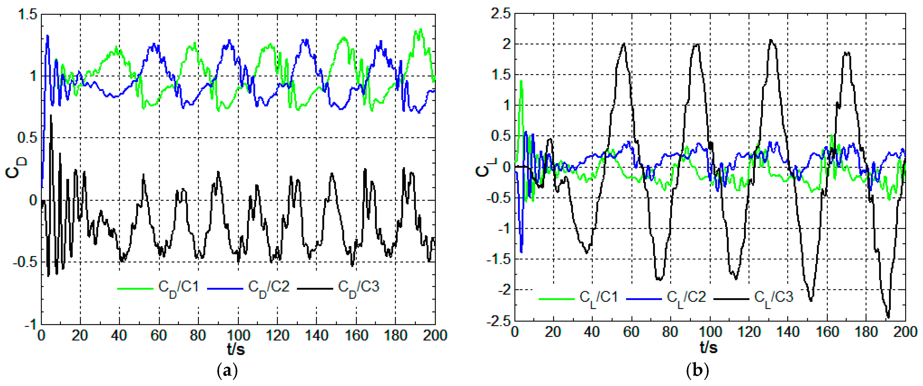
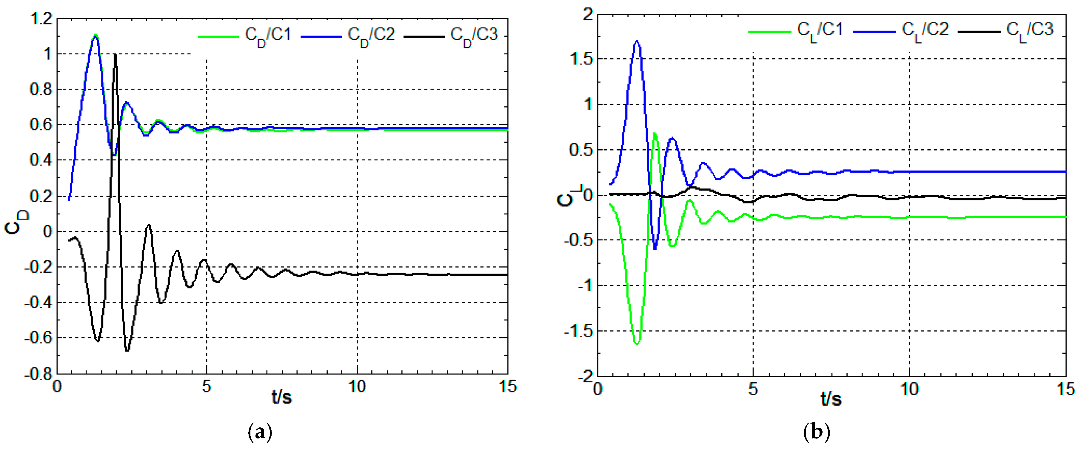
3.2.2. Characteristics of Drag and Lift Coefficients
3.3. Characteristics of Strouhal Number
4. Conclusions
Author Contributions
Funding
Data Availability Statement
Acknowledgments
Conflicts of Interest
Nomenclature
| Re | Reynolds number = ρVD/µ |
| S | distance between centers of two cylinders |
| D | the diameter of a cylinder |
| S/D | spacing ratio |
| β | incidence angle |
| St | Strouhal number f × D/V |
| f | vortex shedding frequency |
| V | flow velocity |
| CD | drag coefficient |
| CL | lift coefficient |
| Cpb | basal pressure coefficient |
| Cp | pressure coefficient |
| Θs | separation angle |
| C’L | lift coefficient pulsation |
References
- Wieselsberger, C. New Data on the Laws of Fluid Resistance; Technical report NACA-TN-84; NASA: Washington, DC, USA, 1921.
- Roshko, A. Experiments on the flow past a circular cylinder at very high Reynolds number. J. Fluid Mech. 1960, 10, 345–356. [Google Scholar] [CrossRef]
- Achenbach, E. Distribution of local pressure and skin friction around a circular cylinder in cross-flow up to Re = 5 × 10⁶. J. Fluid Mech. 1968, 34, 625–639. [Google Scholar] [CrossRef]
- Norberg, C. Fluctuating lift on a circular cylinder: Review and new measurements. J. Fluids Struct. 2003, 17, 57–96. [Google Scholar] [CrossRef]
- Schewe, G. On the force fluctuations acting on a circular cylinder in cross flow from subcritical up to transcritical Reynolds numbers. J. Fluid Mech. 1983, 133, 265–285. [Google Scholar] [CrossRef]
- Rodriguez, I.; Lehmkuhl, O.; Piomelli, U.; Chiva, J.; Borrell, R.; Oliva, A. LES-based study of the roughness effects on the wake of a circular cylinder from subcritical to transcritical Reynolds numbers. Flow Turbul. Combust. 2017, 99, 729–763. [Google Scholar] [CrossRef]
- Ünal, U.O.; Atlar, M. An experimental investigation into the effect of vortex generators on the near-wake flow of a circular cylinder. Exp. Fluids 2010, 48, 1059–1079. [Google Scholar] [CrossRef]
- Capone, A.; Klein, C.; Di Felice, F.; Miozzi, M. Phenomenology of a flow around a circular cylinder at sub-critical and critical Reynolds numbers. Phys. Fluids 2016, 28, 074101. [Google Scholar] [CrossRef]
- Pereira, F.S.; Eça, L.; Vaz, G.; Girimaji, S.S. On the simulation of the flow around a circular cylinder at Re = 140000. Int. J. Heat Fluid Flow 2019, 76, 40–56. [Google Scholar] [CrossRef]
- Sayers, A.T. Flow interference between three equispaced cylinders flow interference between three equispaced cylinders when subjected to a cross flow. J. Wind Eng. Ind. Aerodyn. 1987, 26, 1–19. [Google Scholar] [CrossRef]
- Zdravkovich, M.M. The effects of interference between circular cylinders in cross flow. J. Fluids Struct. 1987, 1, 235–2261. [Google Scholar] [CrossRef]
- Pouryoussefi, S.G.; Mirzaei, M.; Pouryoussefi, S.M.H. Force coefficients and Strouhal numbers of three circular cylinders subjected to a cross-flow. Arch. Appl. Mech. 2011, 81, 1725–1741. [Google Scholar] [CrossRef]
- Zheng, S.; Zhang, W.; Lv, X. Numerical simulation of cross-flow around three equal diameter cylinders in an equilateral-triangular configuration at low Reynolds numbers. Comput. Fluids 2016, 130, 94–108. [Google Scholar] [CrossRef]
- Bansal, M.; Yarusevych, S. Experimental study of flow through a cluster of three equally spaced Cylinders. Exp. Therm. Fluid Sci. 2017, 80, 203–217. [Google Scholar] [CrossRef]
- Bao, Y.; Zhou, D.; Huang, C. Numerical simulation of flow over three circular cylinders in equilateral arrangements at low Reynolds number by a second order characteristic-based split finite element method. Comput. Fluids 2010, 39, 882–899. [Google Scholar] [CrossRef]
- Lam, K.; Cheung, W.C. Phenomena of vortex shedding and low interference of three cylinders in different equilateral arrangements. J. Fluid Mach 1988, 196, 1–26. [Google Scholar] [CrossRef]
- Tatsuno, M.; Amamoto, H.; Ishi-I, K. Effects of interference among three equidistantly arranged cylinders in a uniform flow. Fluid Dyn. Res. 1998, 22, 297–315. [Google Scholar] [CrossRef]
- Meter, F.R. Two-equation eddy-viscosity turbulence models for engineering applications. AIAA J. 1994, 32, 1598–1605. [Google Scholar] [CrossRef]
- DWalters, D.K.; Cokljat, D. A three-equation eddy-viscosity model for Reynolds-averaged Navier–Stokes simulations of transitional flow. J. Fluids Eng. 2008, 130, 121401. [Google Scholar] [CrossRef]
- Mulvany, N.; Tu, J.Y.; Chen, L.; Anderson, B. Assessment of two-equation turbulence modelling for high Reynolds number hydrofoil flows. Int. J. Numer. Methods Fluids 2004, 45, 275–299. [Google Scholar] [CrossRef]
- Meter, F.R. Performance of Popular Turbulence Models for Attached and Separated Adverse Pressure Gradient Flows. AIAA J. 2012, 30, 2066–2072. [Google Scholar] [CrossRef]


| Researcher | Re/104 | CD | C′L | St | Cpb | Cpmin | θs |
|---|---|---|---|---|---|---|---|
| Ivette Rodriguez [6]/LES | 4.2 | 0.994 | 0.316 | 0.214 | −1.024 | −1.548 | 87.5 |
| N. Mulvany [20]/test | 4.2 | −1.18 | −1.241 | ||||
| U. Unal [7] | 4.1 | 1.14 | 0.186 | ||||
| E. Achenbach [3] | 6 | 1.23 | 81.5 | ||||
| C. Wieselsberger [1] | 3~4.2 | 1.18 | |||||
| Anatol Roshko [2] | 10 | −1.18 | |||||
| C. Norberg [4] | 4 | 0.495 | 0.189 | ||||
| Gonter Schewe [5] | 4 | 1.1 | 0.352 | 0.2 | |||
| Alessandro Capone [8] | 6.9 | 95~104 | |||||
| Current work | |||||||
| Realizablek-ε model | 4 | 0.722 | 0.17 | 0.275 | −0.8 | −1.85 | 102~105 |
| SSTk-ω model | 4 | 1.21 | 0.598 | 0.239 | −1.48 | −1.92 | 80~95 |
| k-kl-ω model | 4 | 1.12 | 0.353 | 0.172 | −1.12 | −1.394 | 82 |
| Mesh | Re/104 | S/D | Incidence Angle/° | Number of Cells | CD (C1, C2, C3) |
|---|---|---|---|---|---|
| Mesh 1 | 8.0 | 1.5 | 0 | 80,000 | 0.68/0.747/0.749 |
| Mesh 2 | 8.0 | 1.5 | 0 | 210,000 | 0.727/0.812/0.811 |
| Mesh 3 | 8.0 | 1.5 | 0 | 430,000 | 0.735/0.811/0.807 |
| Researcher | Re/104 | S/D | Incidence Angle/° | CD (C1, C2, C3) | StA | StB | StC |
|---|---|---|---|---|---|---|---|
| S. G. Pouryoussefi et al. [12] | 6.08 | 2.5 | 0 | 0.82/1.08/1.05 | 0.336 | 0.181 | 0.181 |
| A.T.Sayers [10] | 3.0 | 1.5 | 0 | 0.75/0.769 | 0.274 | 0.175 | 0.175 |
| Current work | 3.0 | 1.5 | 0 | 0.735/0.811/0.807 | 0.263 | 0.183 | 0.183 |
| Current work | 6.08 | 2.5 | 0 | 0.846/0.982/0.98 |
| Reynolds Number | 8 × 10⁴ | 2 × 10⁵ | 2 × 10⁶ | 4 × 10⁶ |
|---|---|---|---|---|
| Strouhal number | 0.185 [4] | 0.188 [4] | 0.32 | 0.2 [16] |
| Incidence Angle | Spacing Ratio | Cylinder | Reynolds Number | ||
|---|---|---|---|---|---|
| 8 × 10⁴ | 2 × 10⁵ | 2 × 10⁶ | |||
| 0° | 1.5 | C1 | 0.138 | ||
| C2 | 0.181 | ||||
| C3 | 0.181 | ||||
| 2 | C1 | 0.150 | 0.225 | 0.167 | |
| C2 | 0.175 | 0.200 | 0.300 | ||
| C3 | 0.175 | 0.200 | 0.300 | ||
| 2.5 | C1 | 0.190 | 0.225 | 0.213 | |
| C2 | 0.190 | 0.200 | 0.293 | ||
| C3 | 0.190 | 0.200 | 0.293 | ||
| 60° | 1.5 | C1 | 0.263 | ||
| C2 | 0.263 | ||||
| C3 | 0.075 | 0.033 | |||
| 2 | C1 | 0.230 | 0.250 | 0.300 | |
| C2 | 0.230 | 0.250 | 0.275 | ||
| C3 | 0.092 | 0.100 | 0.075 | ||
| 2.5 | C1 | 0.212 | 0.225 | 0.273 | |
| C2 | 0.212 | 0.225 | 0.273 | ||
| C3 | 0.100 | 0.12 | 0.102 | ||
Disclaimer/Publisher’s Note: The statements, opinions and data contained in all publications are solely those of the individual author(s) and contributor(s) and not of MDPI and/or the editor(s). MDPI and/or the editor(s) disclaim responsibility for any injury to people or property resulting from any ideas, methods, instructions or products referred to in the content. |
© 2024 by the authors. Licensee MDPI, Basel, Switzerland. This article is an open access article distributed under the terms and conditions of the Creative Commons Attribution (CC BY) license (https://creativecommons.org/licenses/by/4.0/).
Share and Cite
Dong, J.; Shi, X.; Yan, G. Effect of Flow Interference between Cylinders Subjected to a Cross Flow over a Cluster of Three Equally Spaced Cylinders. Water 2024, 16, 2165. https://doi.org/10.3390/w16152165
Dong J, Shi X, Yan G. Effect of Flow Interference between Cylinders Subjected to a Cross Flow over a Cluster of Three Equally Spaced Cylinders. Water. 2024; 16(15):2165. https://doi.org/10.3390/w16152165
Chicago/Turabian StyleDong, Jia, Xianrui Shi, and Genhua Yan. 2024. "Effect of Flow Interference between Cylinders Subjected to a Cross Flow over a Cluster of Three Equally Spaced Cylinders" Water 16, no. 15: 2165. https://doi.org/10.3390/w16152165