Article

Experimental Study on the Performance and Internal Flow Characteristics of Liquid–Gas Jet Pump with Square Nozzle

1
College of Metrology Measurement and Instrument, China Jiliang University, Hangzhou 310018, China
2
Shimge Pump Industry (Zhejiang) Co., Ltd., Wenling 317525, China
*
Author to whom correspondence should be addressed.
Water 2024, 16(17), 2358; https://doi.org/10.3390/w16172358
Submission received: 4 July 2024 / Revised: 12 August 2024 / Accepted: 20 August 2024 / Published: 23 August 2024
(This article belongs to the Special Issue Hydraulics and Hydrodynamics in Fluid Machinery)

Abstract

:
In order to ascertain the impact of working water flow rate and inlet pressure on the performance of the liquid–gas jet pump with square nozzle, the pumping volume ratio and efficiency of the liquid–gas jet pump with square nozzle were experimentally investigated at different inlet pressures and working water flow rates. Furthermore, the internal flow characteristics of the liquid–gas jet pump with square nozzle were explored through the utilization of visualization technology in the self-designed square-nozzle liquid–gas jet pump experimental setup. The findings indicate that the pumping ratio of the liquid–gas jet pump increases in conjunction with an elevation in the inlet pressure. Liquid–gas jet pump efficiency is higher at lower inlet pressures, up to 42.48%, and drops rapidly as inlet pressure increases. The pumping volume ratio of the liquid–gas jet pump increases significantly as the working water flow rate increases, and the working water flow rate exerts a minimal effect on the working efficiency of the liquid–gas jet pump. In the context of extreme vacuum conditions, a considerable number of droplets undergo substantial reflux in the posterior section of the throat, with a notable absence of bubbles in the diffusion tube. The size and number of bubbles diminish gradually along the axial direction. The objective of this paper is to provide a reference point for determining the optimal operational parameters for a square-nozzle liquid–gas jet pump in a practical context.

1. Introduction

In practice, vacuum environments are employed in a diverse range of applications, including those pertaining to the aerospace, materials processing, and medical devices sectors [1,2]. The LGJP is a pump that operates on the jet principle. The pump employs a high-speed jet of liquid to drive and accelerate the gas entering the pump body, thereby creating a vacuum through momentum exchange. The LGJP is characterized by a simple structure, high safety standards and reliability, low maintenance costs, and a broad range of applications in the chemical and pharmaceutical industries, environmental engineering, and food manufacturing [3].
The nozzle represents a crucial internal organization of both the LGJP and the ejector. The structure and number of nozzles exert a remarkable influence on the performance of both pumps. A considerable body of research has been conducted on the nozzle. Huang F designed five distinct nozzle shapes for the purpose of conducting experiments on the effect of peculiarities of high-pressure water jets. The experimental findings indicated that the circular-nozzle water jets exhibited greater clustering, while the elliptical-nozzle water jets demonstrated the most dispersed patterns, with the smallest central impact [4]. Zebing Wu [5] conducted a numerical simulation of the cavitation performance of five distinct nozzle shapes: regular, flat, Y, cross, and star. It was determined that the flat-type nozzle exhibited a greater volume of the gas phase following the occurrence of cavitation, while the star-type nozzle demonstrated a comparatively reduced volume. Lin Hua [6] studied the influence of nozzle outlet shape and water dispersion structure on the characteristics of spray water droplets. The results showed that the auxiliary water dispersion structure, such as square nozzle and rocker arm, can strengthen the dispersion degree of the water jet and reduce the droplet striking kinetic energy at the end of the range. In a series of experiments, Yin Li [7] investigated the effect of nozzle structure on unsteady jet thrust. The effect of three different types of nozzle inner cavity structures, namely, conical, conical–straight, and Wyszynski type, and three different types of nozzle lip side structures on the jet thrust were also analyzed. The results demonstrated that the mean unsteady jet thrust was the greatest for conical nozzles. Maosen Xu [8] employed numerical simulations to investigate the influence of nozzle position on the performance of the novel annular jet pump. The results indicated that there exists an optimal value for the distance of the working nozzle from the wall, at which point the efficiency of the annular jet pump is at its maximum. Jiaming Zhang [9] examined the effect of a novel nozzle configuration on the functionality of compact jets. Their findings indicated that the conventional sharp right-angle contraction water jet approach is inapplicable when the nozzle aperture is substantial and the pressure is below 30 MPa. Wenjuan Chen [10] employed an experimental approach, selecting a range of nozzle configurations, including straight, convergent, convergent–divergent, and divergent nozzles, to gain insights into their effect on engine performance. The results indicated that the thrust increase in the straight nozzle was generally superior to that of the divergent nozzle. In her study, Weina Fu [11] employed numerical simulations to investigate the effect of main nozzle outlet diameter and diverging section length on the performance of jet pumps at varying entrainment pressures. The results indicated that there are optimal values for the main nozzle outlet diameter and dispersion cross-section length. Furthermore, the maximum injection coefficient corresponding to the dispersion cross-section length is not significantly different from the nonoptimal values. Qianglong Yun [12] conducted a series of experiments examining the hydraulic performance of the LGJP with fan nozzles. The findings revealed that the maximum gas–liquid ratio achieved by the shaped nozzles exceeded that of the circular nozzles at higher area ratios. Guijun Gao [13] conducted numerical simulations to investigate the influence of the contraction angle of the throat nozzle section on the flow field peculiarity of an LGJP. The results demonstrated that the contraction angle exerts a minor effect on the flow ratio, while it has a pronounced effect on the pressure ratio and efficiency. Isataev [14] experimentally studied the average flow characteristics of turbulent free gas emitted from a square nozzle, and adjusted the difference in the presence and absence of external sound effects. The results showed that the flow characteristics of turbulent free gas emitted in the absence of external sound effects were better than those in the presence of external sound. Busov [15] conducted an experimental study on the boiling characteristics of a superhot water jet with an outlet through a square nozzle, and found that when T = 540 k, the whole nozzle was unstable, and the relationship between the change of jet opening angle and the degree of overheating of the working medium was obtained under various boiling modes with dimensionless coordinates. Pullarao [16] conducted an experimental study on the effect of metal mesh at the nozzle outlet on the heat transfer of a square impact jet, and analyzed the jet heat transfer characteristics of three kinds of mesh with area gap value. It was found that the presence of mesh acts as a turbulent accelerator, making the Nussel number reach its maximum value when the distance from the smaller dimensionless jet to the plate is 2, rather than when the distance from the higher dimensionless jet to the plate is 4.5.
A significant number of scholars have conducted research on LGJPs through theoretical analyses, numerical simulations, and experiments. Witte [17] proposed the notion of the Euler number as an acausal constant that responds to the compression strength of the gas during the mixing process of water and gas in an LGJP. Based on this concept, the intricate two-phase flow dynamics within the liquid–gas mixing process have been elucidated, and the theoretical framework of the mixing excitation wave has been established. Dingjia Liao [18] derived the fundamental performance equations of the liquid–LGJP through theoretical derivation and analogized with the outcomes of analogous foreign research to obtain the expressions of each correction coefficient in the model. Zhang [19] undertook a comprehensive review of the development of LGJPs, encompassing theoretical derivation, experimental testing, simulation, and practical application. In a study conducted by Ge Q, the structural parameters of an LGJP were designed and analyzed. The findings revealed that the pump efficiency reached its maximum value when the throat–nozzle distance was 1.5 times the nozzle diameter and the nozzle–throat–area ratio was 5.86 [20,21]. Ri Xing [22] conducted a three-dimensional simulation study of a jet pump using fluent 19.0, concluding that the secondary flow vacuum of an LGJP increases with the increase in the primary flow rate. Furthermore, the study derived the optimum area ratio for higher vacuum and efficiency. Zhou [23] conducted an optimization study on the flow path of a liquid–air jet pump within a smart toilet spray bar. The study found that the optimized toilet cleaning spray model effectively reduces the number of spins, increases the air intake, and reduces the pressure loss. Wen Chen [24] conducted a more comprehensive simulation analysis of the structural parameters of the LGJP. The results indicated that the optimal throat nozzle distance is 1.5 times the diameter of the nozzle, resulting in the highest pump efficiency. Additionally, the area ratio of 4 to 7 was found to enhance the jet doping effect, while varying nozzle structures within the jet pump exhibited a significant effect on the internal flow peculiarities. In a series of experiments, Bonnington [25] investigated the effect of jet velocity and throat length on the efficiency of jet pumps. The findings revealed that as jet velocity increases, the coiling efficiency of jet pumps declines. However, within a specific range, the longer the throat, the higher the coiling efficiency. In an experimental study, Ondrej [26] investigated the potential for enhancing the gas entrainment rate of an LGJP. The findings revealed that the gas entrainment rate of a jet pump can be increased exponentially by utilizing a high-loss nozzle that generates an incoherent liquid jet, as compared to the performance of a coherent liquid jet. Cunningham [27] analyzed a significant number of experimental results and concluded that in optimal working conditions, when the throat length-to-diameter ratio, throat diameter, and other structural parameters of the liquid–air jet pump are appropriate, the air isothermal compression rate of the LGJP can exceed 40%. Furthermore, Witte [17] employed the 19-hole multinozzle structure in a variety of operational scenarios for experimental comparison, ultimately achieving an air isothermal compression rate of 40%. By comparing and analyzing the results with the experimental results, Chuanchang Gao [28] found that the efficiency of the pulsed liquid–air jet vacuum pump is 4% to 15% higher than that of the ordinary liquid–air jet vacuum pump due to the intermittent jet of the pulsed liquid–air jet pump which makes the water hammer effect exist in the operation. Qingjiang Xiang [29] conducted pressure measurements on the wall of a diffusion tube at varying gas–liquid volume flow ratios and observed that at a maximum pressure increment range of 250 kPa within the diffusion tube, the pressure initially decreases and then rises in the direction of the wall, while the velocity decreases by 20% along the central axis of the diffusion tube. Xu [30] conducted an experiment to investigate the effect of varying operational parameters on the performance of the LGJP. The study analyzed the change in pumping volume and pumping ratio of the LGJP as a function of inlet flow rate, temperature, and pressure. The findings indicated that the operational efficacy of the LGJP exhibits a slight decline with the enhancement of the working water flow rate. Conversely, the pumping volume ratio of the system demonstrates an increase with the elevation of the inlet pressure. However, the efficiency declines precipitously when the inlet pressure surpasses 70 kPa. The nozzle structure of the traditional LGJP is mostly circular or elliptical in structure. This study improved the structure of the traditional LGJP and redesigned the square-nozzle structure of the LGJP for experimental research. LGJPs with a square nozzle have better performance than jet pumps with other nozzle structures [30].
Most of the above experimental studies on LGJP only studied the external peculiarities, and the existing literature lacks consideration of the internal flow peculiarities of LGJPs. A comparison of the performance of square-nozzle and round-nozzle LGJPs under identical operational conditions revealed that the former exhibited superior performance to the latter [30]. Consequently, this study was focused on the internal flow peculiarities of a square-nozzle LGJP. This paper presents a redesigned and manufactured plexiglass-type LGJP test piece, along with an experimental bench, which was set up to study the internal flow peculiarities of the LGJP. The theoretical guidance provided in this paper was used to inform the design and manufacture of the test piece. It is of practical significance to explore the changes of gas–liquid mixed two-phase flow and their influences on each other under different working conditions to further improve the working efficiency of LGJPs.

2. Experimental Design

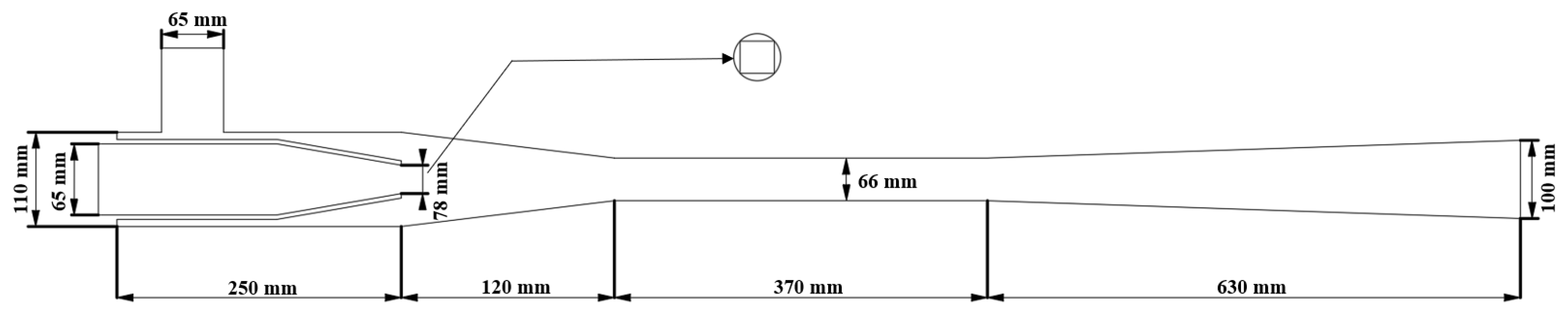
2.1. The Structure and Working Principle of the LGJP

The LGJP is a vacuum mechanical apparatus that employs a high-speed liquid jet to pump gas. Its structural components include a nozzle, throat, diffusion tube, suction chamber, mixing chamber, air inlet, and water inlet, as illustrated in Figure 1. In the context of the liquid–gas two-phase fluid movement process, the working fluid is observed to enter the jet pipe under conditions of pressure (Pg) and velocity (Vg). In the subsequent phase of nozzle compression and acceleration, the jet and the fluid pressure and velocity undergo a transformation, resulting in a reduction in pressure to P1 and an increase in velocity to V1. It is noted that the pressure within the suction chamber, designated as P1, is observed to be less than the suction fluid pressure Pa. This discrepancy is attributed to the influence of the suction gas, which is observed to be drawn into the suction chamber under the action of the pressure difference. The two-phase fluid within the pipe undergoes a process of mutual mixing and exchange, whereby momentum and energy are transferred between the phases. This exchange of momentum and energy commences at the pipe entrance and continues until the two-phase flow is fully mixed. As a result of this mixing, the pressure of the mixed fluid changes in accordance with the second pressure coefficient (P2), while the velocity changes in accordance with the second velocity coefficient (V2). Upon completion of the mixing process, the mixed fluid enters the diffusion tube. As the overflow area increases, the fluid’s motion velocity is reduced to V3, resulting in the conversion of kinetic energy into pressure potential energy. This leads to an increase in pressure to P3, which is greater than the outlet ambient pressure of the diffusion tube. Consequently, the mixed fluid is expelled from the tube through an LGJP, completing the work of the jet flow [31].
This paper introduces the volumetric flow rate ratio (q) and operating efficiency ( η ) of the LGJP as performance parameters [32].
q = Q a Q g
The area ratio (m) [33] is calculated as follows:
m = f b f a
In the aforementioned formula, fb represents the throat cross-sectional area, fa represents the nozzle cross-sectional area, Q a represents the pumped gas flow rate, and Q g represents the working liquid flow rate. The essence of the working efficiency of the LGJP can be regarded as the energy gained by the pumped gas and the ratio of the energy lost by the working liquid.
The energy gained by the pumped gas can be expressed by the following equation [30]:
W a = v a v c p d v = v a v c p a v a v x d ( v x ) = p a v a ln ( v c v a )
In the aforementioned formula, the value of v a represents the velocity of the gas at the point of its entry into the LGJP, the value of v x represents the velocity of the gas along the axis of the LGJP, and the value of v c represents the velocity of the gas at the point of its exit from the LGJP.
In accordance with the ideal gas equation, the following derivation can be made on the assumption that the gas is undergoing an isothermal compression process with a constant temperature and no change in the gas medium [34]:
W a = p a v a ln ( v c v a ) = p a v a ln ( p a p c )
The energy loss of the working fluid can be expressed as follows:
W g = Q g Δ p
In the aforementioned equation, the value of Δ p represents the total pressure difference between the working fluid as it enters the LGJP and as it exits the process of loss. Consequently, the working efficiency is expressed as follows:
η = W a W g

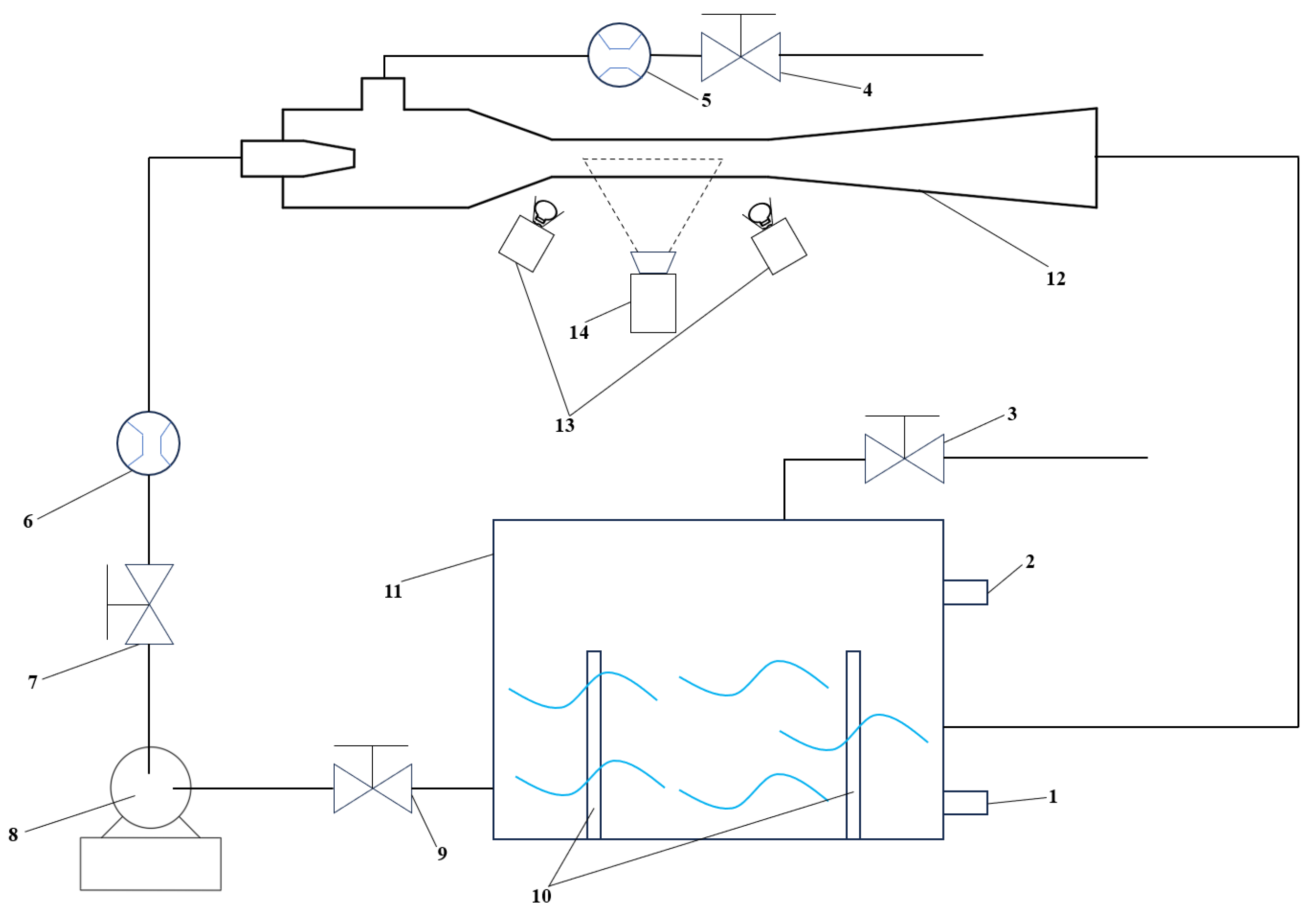
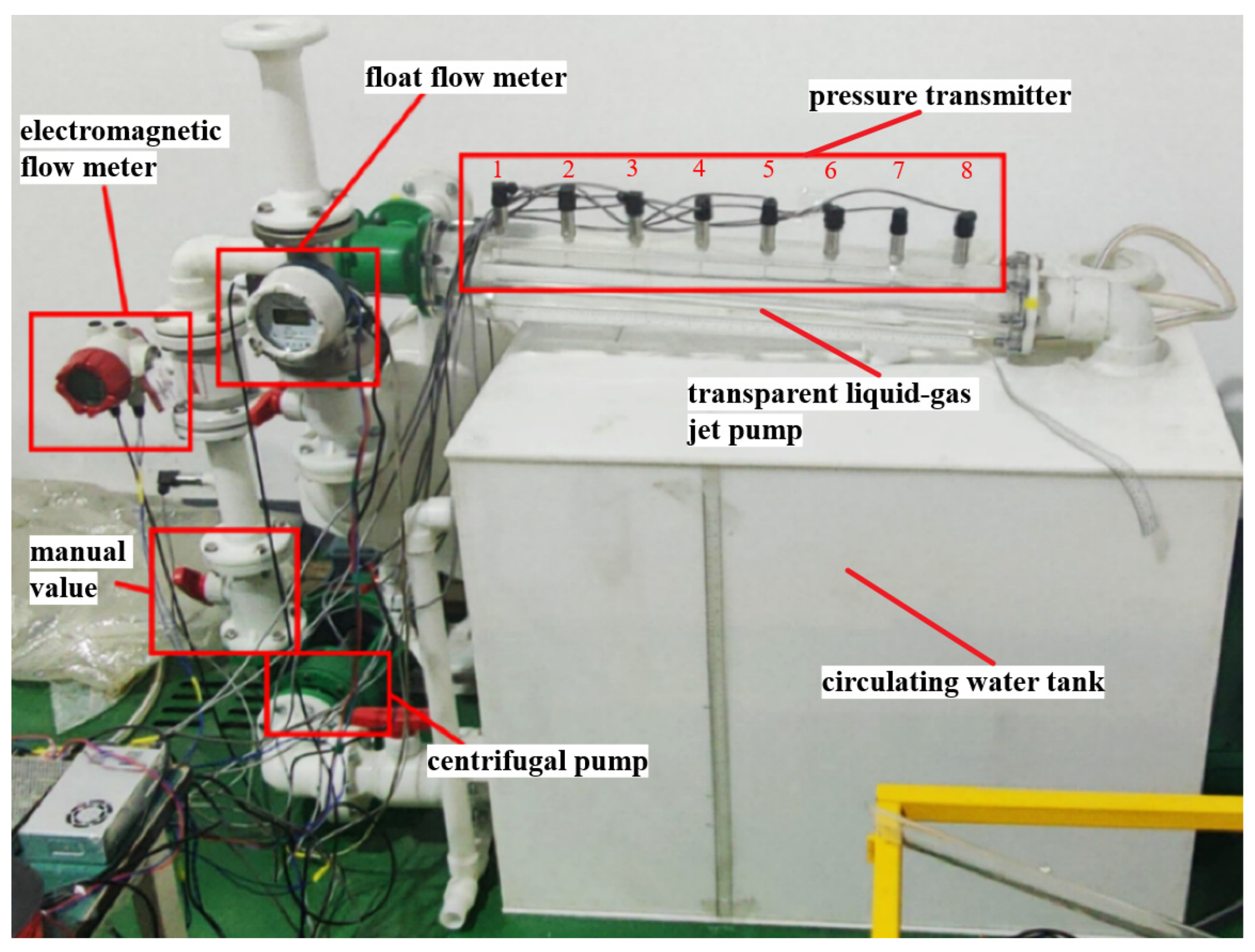
2.2. Experimental Setup

The theoretical design of the LGJP experimental bench, in accordance with the standard, was employed to test the instrumentation. The float flowmeter was used to measure the gas flow, while the electromagnetic flowmeter was employed to measure the flow of working water. The circulating water tank employed in the experiment is constructed from RPP material, which serves to provide the requisite circulating water. The experimental apparatus is equipped with a number of pressure-taking apertures for the purpose of pressure testing the experiment. The water tank is similarly equipped with an air outlet and a highwater level overflow port.
The configuration of the experimental bench and camera position is illustrated in Figure 2. As the LGJP generates a considerable number of bubbles during the mixing process with water when pumping gas, and a substantial number of bubbles are present in the throat and diffusion tube, visualization experiments are employed in order to capture the flow details as well as the changes in the bubbles. In order to meet the visual volume requirements of the visualization experiments, a Plexiglas-type LGJP test piece was redesigned and manufactured. The visualization experiment and each step operation were carried out in strict accordance with the relevant requirements. In order to avoid distortion of the observation phenomenon due to the refractive index of the plexiglass in the observation direction, the outer profile of the section of the plexiglass pipe was designed as a rectangle, and a pressure hole was set on the transparent plexiglass for pressure monitoring. A high-speed camera was positioned at right angles to the direction of the Plexiglas observation surface, with a large aperture and a long depth of field. The lens focus was adjusted until the bubbles of the mixed two-phase flow in the photographed throat and diffusion tube were clearly identifiable. In high-speed photography mode, the shutter speed is in the thousands, and robust light sources are positioned on either side of the shooting area to ensure that the subject is adequately illuminated. High-speed photography was conducted using a Thousand Eyes Wolf high-speed camera set at 5000 fps in shooting mode, encompassing the range from the inlet of the throat to the outlet of the diffusion tube. This enabled the capture of the bubble changes occurring during the process of bubble generation to bubble collapse or discharge in a mixed two-phase flow.
The physical diagram of the experimental setup of the LGJP is presented in Figure 3. In order to guarantee the stability of the fluid flow state when passing through the sensor, it is essential to install the flowmeter prior to the remaining 5–10D of the pipeline length. Additionally, the pipeline pressure holes must be positioned in front of the liquid flowmeter and at the rear of the pressure regulator tank. This configuration enables the measurement of pressure to be both stable and accurate. The LGJP and diffusion tube configuration comprise a total of eight pressure holes, enabling the monitoring of the LGJP’s operational status in a mixed two-phase flow environment. Figure 4 illustrates the dimensions of the square-nozzle LGJP.

3. Results and Discussions

3.1. External Characterization

We regulated the opening of the inlet valve to alter the pressure at the inlet, as illustrated in Figure 5a for a 20 °C water temperature environment, under varying conditions of the LGJP’s working water flow rate, LGJP pumping gas volume ratio, and inlet pressure change relationship. Figure 5a illustrates that the pumping volume ratio is essentially linearly correlated with the inlet pressure, as the inlet pressure rises at a consistent working fluid flow rate. When the inlet pressure is modified while the working water flow rate is maintained, the pumping volume ratio rises and attains a maximum value, designated as qmax. When the inlet pressure (Pa) is equal to 90 kPa and the working water flow rate (Qg) is equal to 58 m3/h, that is to say when the inlet valve and the inlet valve are in a fully open condition, the maximum volume ratio (qmax) is equal to 4.93. Figure 5b shows the variation curve of the efficiency of the LGJP with the inlet pressure. From the figure, it can be concluded that the inlet pressure has a significant effect on the efficiency of the LGJP; when Pa ≤ 70 kPa, the working efficiency is higher and smoother, and when Pa > 70 kPa, the working efficiency decreases rapidly. The highest efficiency point is obtained when Pa = 60 kPa, and the working efficiency reaches 42.48%.
Figure 6a illustrates the relationship between the pumping volume ratio and the working liquid water flow rate as the flow rate of the working liquid water is varied. From the figure, it can be observed that, under the condition of maintaining the same inlet pressure, the working water flow rate and the pumping volume ratio exhibit a linear relationship. Figure 6b illustrates the relationship between the working water flow rate and the working efficiency of the LGJP. It can be observed that the working efficiency of the working water flow rate exhibits a slight decline, yet this decline is limited. The maximum change in working efficiency is only 9.17%, which is considerably less than the effect of the inlet pressure on the working efficiency.
In order to investigate the performance of a square-nozzle LGJP for vacuum pumping, the gas valve was completely closed and the gas inside the sealed container was pumped through the air inlet. Upon extraction of the gas from the sealed container, a notable decline in pressure was observed initially, accompanied by the normal functioning of the LGJP. However, a subsequent reduction in pressure and gas density within the container was accompanied by the onset of audible noise and pronounced vibration from the LGJP. Eventually, the pressure and gas density within the container reached a state of equilibrium, accompanied by a notable reduction in noise and vibration from the LGJP. At this juncture, the experimental data collection commenced.
The maximum achievable vacuum pressure at the inlet of the LGJP is dependent on the working water flow rate, as illustrated in Figure 7. It can be observed that as the water flow rate decreases, the vacuum pressure increases. When the water valve is fully open and the gas valve is completely closed, the energy of the working water is converted into kinetic energy, resulting in a flow rate of 62 m3/h. At this juncture, the temperature of the experimental water is 20 degrees Celsius, and the ultimate vacuum pressure attained is 6.47 kilopascals. As the opening of the working water valve was gradually reduced, the ultimate vacuum pressure at the inlet was subsequently increased. This resulted in experimental results that were in good agreement with those previously measured by R.G. Cunningham [27].

3.2. Internal Mobility Analysis

In the event that the inlet pressure is less than 40 kPa, the liquid and gas jet pump will commence pumping gas, which will result in the generation of significant vibration. The float flowmeter is highly susceptible to vibration in such circumstances. In particular, in situations where the pumping gas flow is relatively low, the pressure differential between the front and rear of the float flowmeter is minimal. During the experimental procedure, the vibration caused by the movement of the float results in a significant discrepancy in the data obtained from the central of the float. Consequently, the data obtained from this range of conditions are deemed unreliable and cannot be utilized. Figure 8 illustrates the pressure change curves in the throat and diffusion tube under varying inlet pressure conditions. The pressure change curves in the throat and diffusion tube demonstrate a clear correlation between pressure size and inlet pressure. However, the pressure size at the outlet of the diffusion tube remains largely independent of the inlet pressure. The lowest pressure is observed at the throat inlet, with an increase in pressure at each subsequent measurement location. The pressure measured at the three pressure measurement points at the throat rises steadily, while the mixed two-phase flow at low inlet pressure undergoes a rapid pressure increase in the diffusion tube. This increase in pressure occurs at a much faster rate than that observed at high inlet pressure. In some instances, the pressure of the mixed two-phase flow at low inlet pressure may exceed that of the two-phase fluid at high inlet pressure at the same measurement point. Ultimately, the pressure of the mixed two-phase flow at low inlet pressure reaches atmospheric ambient pressure at the outlet of the diffusion tube.
The inlet pressure was gradually reduced at 10 kPa intervals, while maintaining the working water flow rate at 58 m3/h. The two-phase flow in the transparent pipe made of Plexiglas was photographed using a high-speed camera, as illustrated in Figure 9. As the pressure at the inlet decreases gradually, the phase of relative motion of the liquid–gas jet in the throat, in which the liquid and gas are in motion relative to one another, becomes relatively shorter. The length of the longest phase of relative motion of the liquid–gas jet is 144 mm, and the phase of droplet motion begins at a point that is 2.19 times the diameter of the throat, as illustrated in Figure 10. In comparison to the liquid–gas jet condition with high inlet pressure, the liquid–gas jet will enter the droplet motion section at an earlier point under the condition of low inlet pressure. This results in a notable increase in the number of droplets dispersed outside the main body of the jet in the droplet motion section. Furthermore, the bubble flow phenomenon around the jet occurs after mixing with the high-speed airflow.
Shown in Figure 11 is the change of flow pattern after the mixed flow enters the diffusion tube under different inlet pressure conditions. Compared with the flocculent flow at high inlet pressure, the foam flow at low inlet pressure is more uniformly distributed, and the gas–liquid mixing effect is better, but it can be seen from Figure 5a that the ability to pump gas at this time is not as good as that at high inlet pressure. In summary, Figure 8a illustrates how the pressure within the diffusion tube experiences a transient spike due to incomplete gas-liquid mixing and the presence of a flocculent flow pattern. The pressure spike, which is a temporary anomaly, is followed by a return to the original trend as the system stabilizes. The presence of droplets and the flocculent effect before the take-off holes contribute to this observed pressure fluctuation, indicating a complex interplay of fluid dynamics and flow patterns within the tube.
According to Figure 8, for the same pressure measurement position, the rate of pressure increase in the diffusion tube at low inlet pressure conditions is much greater than the rate of pressure change measured at high inlet pressure. As shown in Figure 11, under the condition of high inlet pressure (Pa = 90 kPa), the liquid–gas mixing effect is not ideal, and a large number of droplet clusters are unevenly distributed in the diffusion tube, which leads to the measured pressure in the diffusion tube being lower than the actual two-phase fluid pressure under this measurement point. In contrast, at low inlet pressure (Pa = 40 kPa), the foam flow in the diffusion tube is uniformly distributed inside the diffusion tube and is in full contact with the wall, so the measured pressure matches the actual pressure to a higher degree.
Combined with the results of external characterization experiments, it is concluded that the working efficiency is closely related to the degree of mixing of the gas and liquid phases. After a drop in inlet pressure, the gas–liquid two-phase mixing in the throat is better, and the diffusion tube moves in a fine foam flow type. Under a high inlet pressure environment, the liquid–gas two-phase mixture in the diffusion tube showed a flocculent flow pattern and was not fully distributed in the diffusion tube. In summary, the lower efficiency observed is due to the incomplete mixing of liquid and gas, the formation of large droplet masses, the effects of low inlet pressure causing expansion of the overflow tube, and the resulting non-uniform foam flow. High-speed photography serves as a valuable tool in visualizing these issues and understanding the detailed behavior of the foam flow. To improve efficiency, adjustments in mixing techniques, pressure conditions, and flow dynamics may be necessary.
In the working water flow rate in the smaller (Qg < 40 m3/h) conditions, the jet liquid struggles to sustain a stable volume of gas suction into the liquid–gas jet vacuum pump for mixing the jet, and the suction gas flow rate drops, so it can be assumed that the LGJP does not have the ability to suction gas in the range of the working water flow rate, and the range of working conditions of the test data is not used.
The pressure changes in the throat and diffusion tube are shown in Figure 12. As shown in Figure 12a, when the inlet pressure Pa = 90 kPa, the liquid–gas mixed two-phase flow undergoes a pressure surge at the front section of the diffusion tube, which is followed by a rapid decrease, and then it continues to rise. As shown in Figure 12c, when the inlet pressure Pa is 60 kPa, the pressure inside the diffusion tube starts to change significantly under different working water flow rate operating conditions, and the pressure change inside the diffusion tube rises significantly faster with the decrease in working water flow rate under low inlet pressure (Pa < 60 kPa).
By adjusting the inlet valve, the working water flow rate was gradually reduced at intervals of 5 m3/h. High-speed photography was used to photograph the transparent hose, as shown in Figure 13. As the working water flow rate is reduced, observe the changes in the liquid–gas jet flow pattern. The water jet, as it emerges from the nozzle, maintains a stable phase of liquid–gas relative motion in the initial section of the pipe. The distance over which this phase is maintained is dependent on the size of the working water flow rate. As the working water flow rate is reduced, the maintenance distance of the liquid–gas relative motion stage is shortened. The length of the liquid–gas relative motion stage in the longest throat is 144 mm, and the liquid droplet motion stage commences at 2.19 times the diameter of the throat, as illustrated in Figure 14.
In the context of maintaining a constant inlet pressure, the liquid jet entrained gas movement resulted in the formation of a gas flow band, which required a constant energy input to maintain its stability. Meanwhile, the speed of the working water’s movement altered the kinetic energy of the jet liquid, leading to a reduction in the working water flow rate. This, in turn, affected the speed and kinetic energy of the jet liquid, which subsequently resulted in a decline in the ability to maintain a more stable relative movement. At this juncture, the droplet movement stage commenced.
According to the external peculiarity test results, it can be seen that under the condition of constant inlet pressure, the working water flow rate is basically linear with the gas–liquid volume ratio. Under the working condition with the inlet valve fully open (Pa = 90 kPa), the liquid–gas two-phase mixed flow in the diffusion tube was not completely mixed, as shown in Figure 15. There is an obvious uneven distribution of the two-phase fluid in the diffusion tube, and part of the gas always remains in the state of a continuous medium, which is not completely mixed with the liquid, resulting in a low efficiency of pumping gas. Combined with the external peculiarities of the experimental results, it can be concluded that the liquid and gas phases are not mixed in the pipe when the working water flow rate is higher, so there is no obvious relationship between the working efficiency and the working water flow rate.
The pressure change curves of the throat and diffusion tube when the gas valve is completely closed are shown in Figure 16, from which it can be seen that the jet enters the throat and produces a significant pressure change, the pressure in the throat rises sharply, the pressure change tends to stabilize after the fluid moves to the diffusion tube, and there is a very small increase in the pressure as it flows towards the outlet of the diffusion tube.
The pressure in the pipe is significantly affected by the working water flow, and the pressure at measuring points 3 and 4 of the pipe does not change as the working water flow increases. The pressure at measurement points 1 and 2 was lower under high flow conditions, especially when the working water flow rate was 62 m3/h; when the inlet valve was fully open, the pressure in the pipe reached a minimum of 27.2 kPa.
As can be seen from the results of the external peculiarity experiment, the working water flow rate reaches 62 m3/h when this experimental setup extracts the maximum ultimate vacuum, which is taken under the stable operation of the liquid–gas jet vacuum pump, as shown in Figure 17.
When pumping ultimate vacuum, the inlet pressure is extremely low, and because the gas valve is closed without gas intake, the gas in the liquid–gas jet vacuum pump almost does not flow, so the jet in the throat maintains a very short distance in the phase of liquid–gas relative motion, only 26 mm. There is a great speed difference between the high-speed flowing liquid and the gas that almost does not produce axial flow, and in the phase of droplet motion, the jet liquid generates a violent surface wave, and a large number of droplets break away from the main body of the liquid.
A significant pressure differential exists between the front and rear sections of the throat, resulting in a pronounced reflux phenomenon at a depth of 250 mm, as illustrated in Figure 18. This phenomenon can be attributed to the two-phase flow of liquid and gas within the liquid droplet movement stage, which facilitates the exchange of speed and energy. However, the gas within the throat does not reach the speed of the liquid droplets, and there is insufficient gas for compression and mixing with the liquid droplets to form a foam flow. Consequently, there is no foam flow movement stage in the evacuation process.
The change in bubbles in the diffusion tube is shown in Figure 19. The gas–liquid mixture present in the diffusion tube compresses the discrete bubbles in the fluid as the pressure rises with axial movement. In summary, the decrease in bubble count and diameter as bubbles move towards the exit of the diffusion tube is primarily due to the increasing pressure causing bubble collapse and changes in bubble dynamics such as coalescence and diffusion. These factors collectively lead to fewer, smaller bubbles near the exit compared to those observed earlier in the tube.
After digital image processing of the tiny bubble images taken in the equal-area diffusion tube at different positions in the diffusion tube selected in Figure 19, the bubble group pictures in the upper area of the central axis of the diffusion tube were captured, and the results are shown in Figure 20. The figure shows that the bubbles are mostly distributed in the front section of the diffusion tube, there are very few bubbles near the outlet of the diffusion tube, and the number of bubbles decreases with the axial movement in the diffusion tube. The accuracy of the result can be further verified by the distribution of the wall pressure along the axial movement direction of the diffusion tube.

4. Conclusions

(1)
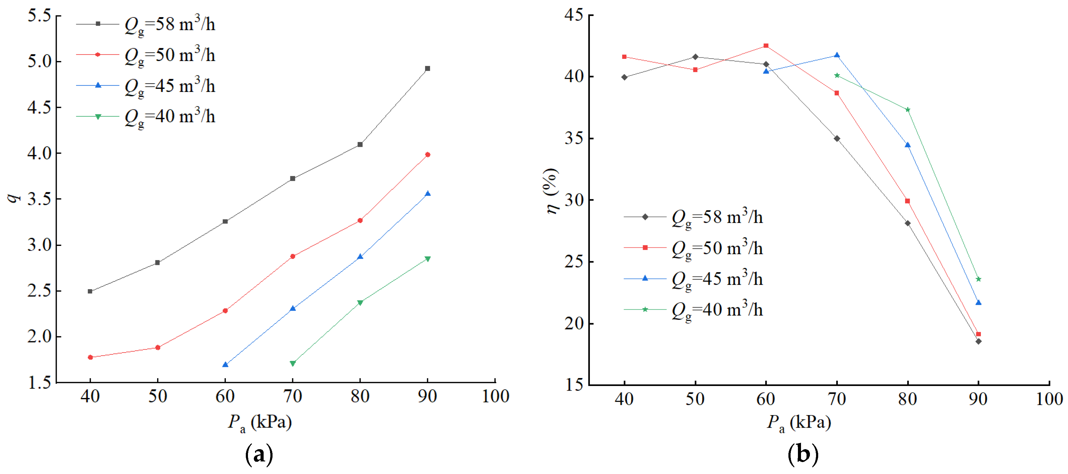
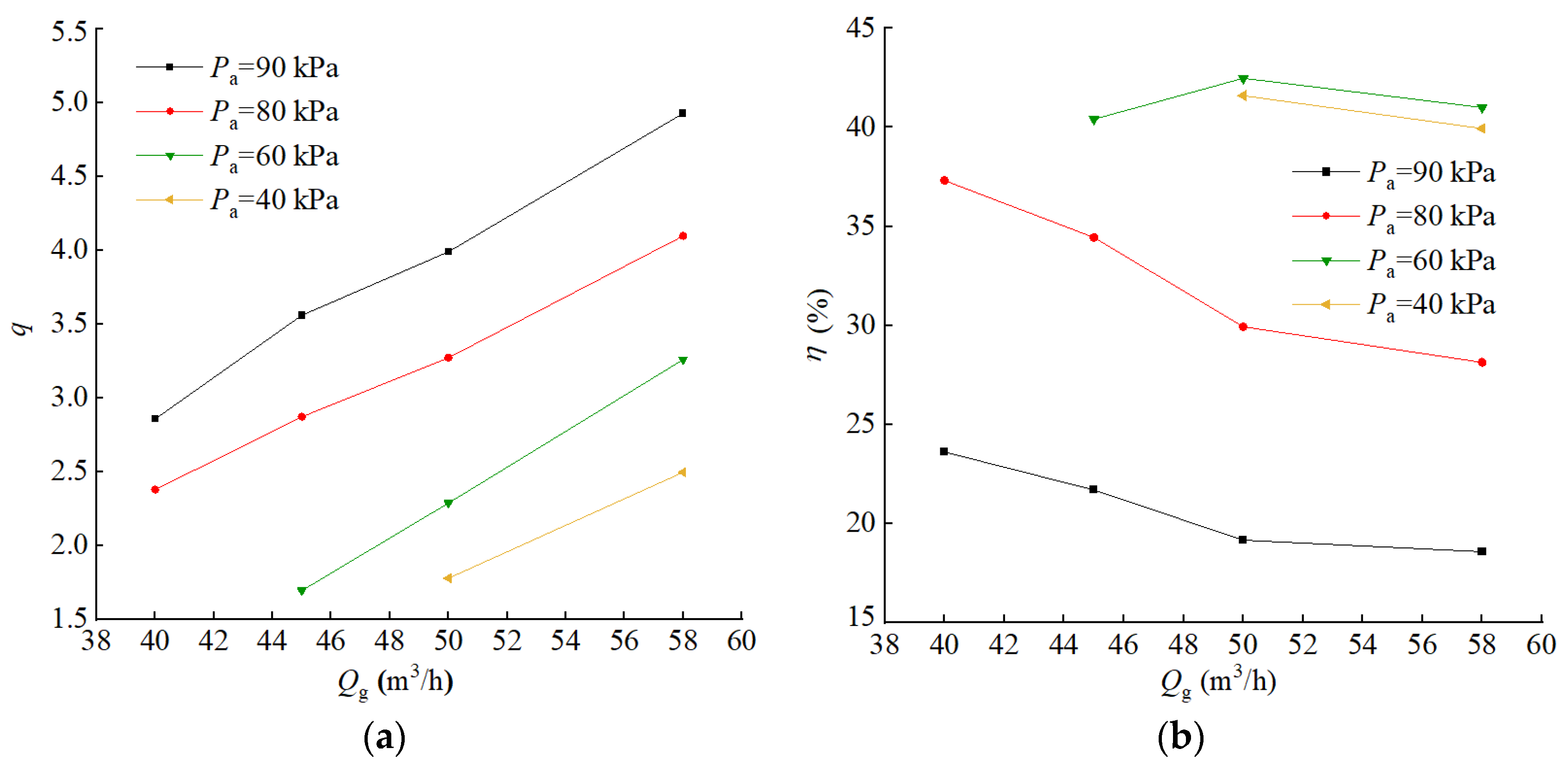
As the inlet pressure rises, the square-nozzle liquid–gas jet vacuum pump pumping volume ratio increases, the maximum volume ratio qmax is 4.93, and the efficiency is higher at low inlet pressures, up to 42.48 per cent, and decreases rapidly at high inlet pressures.
(2)
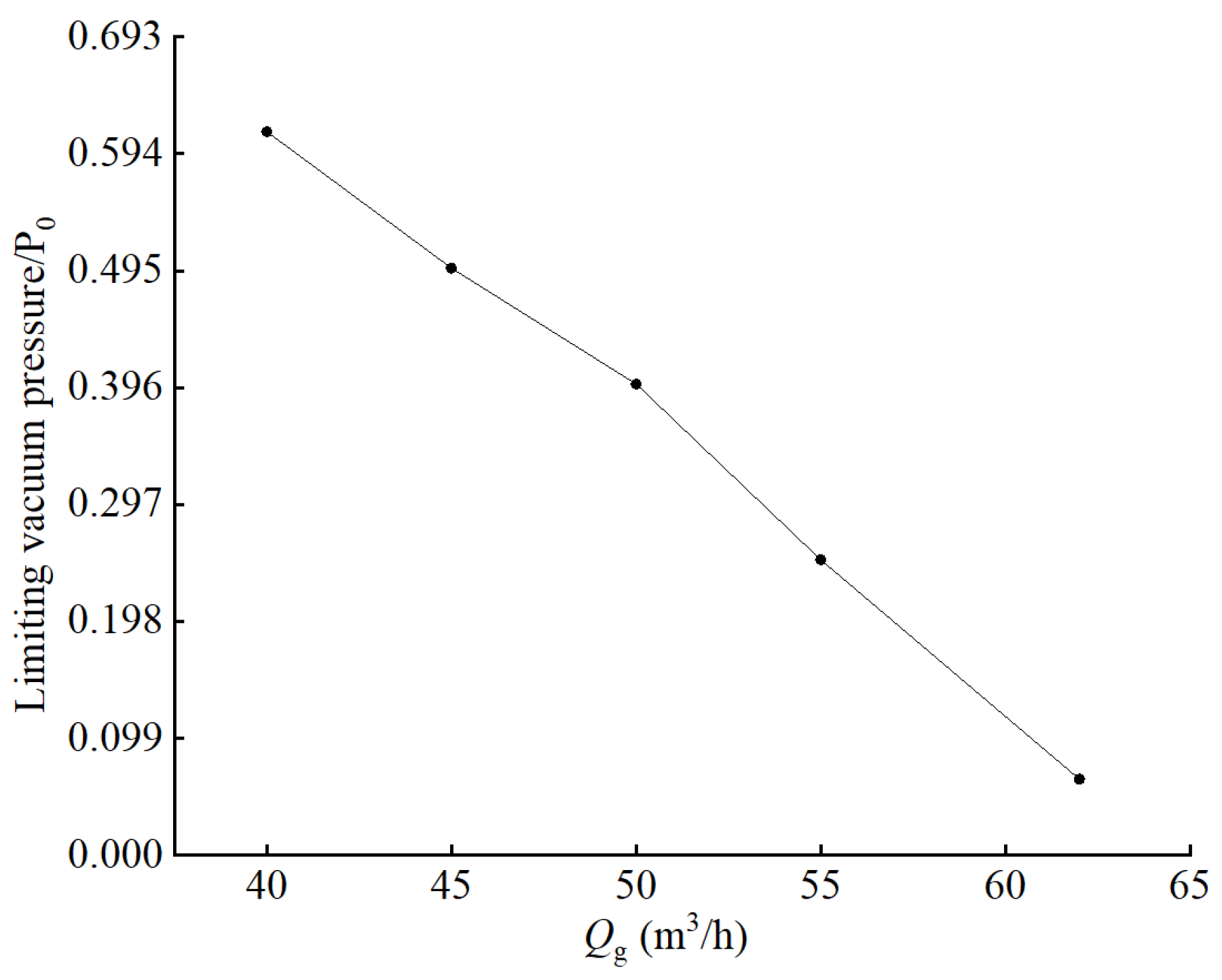
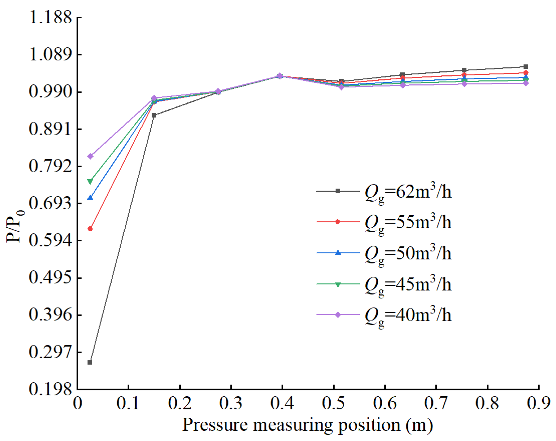
The pumping volume ratio of the square-nozzle LGJP will increase significantly with the increase in the working water flow rate. The working water flow rate has less influence on the working efficiency, the ultimate vacuum pressure decreases with the increase in the working water flow rate, and the lowest ultimate vacuum pressure is 6.47 kPa.
(3)
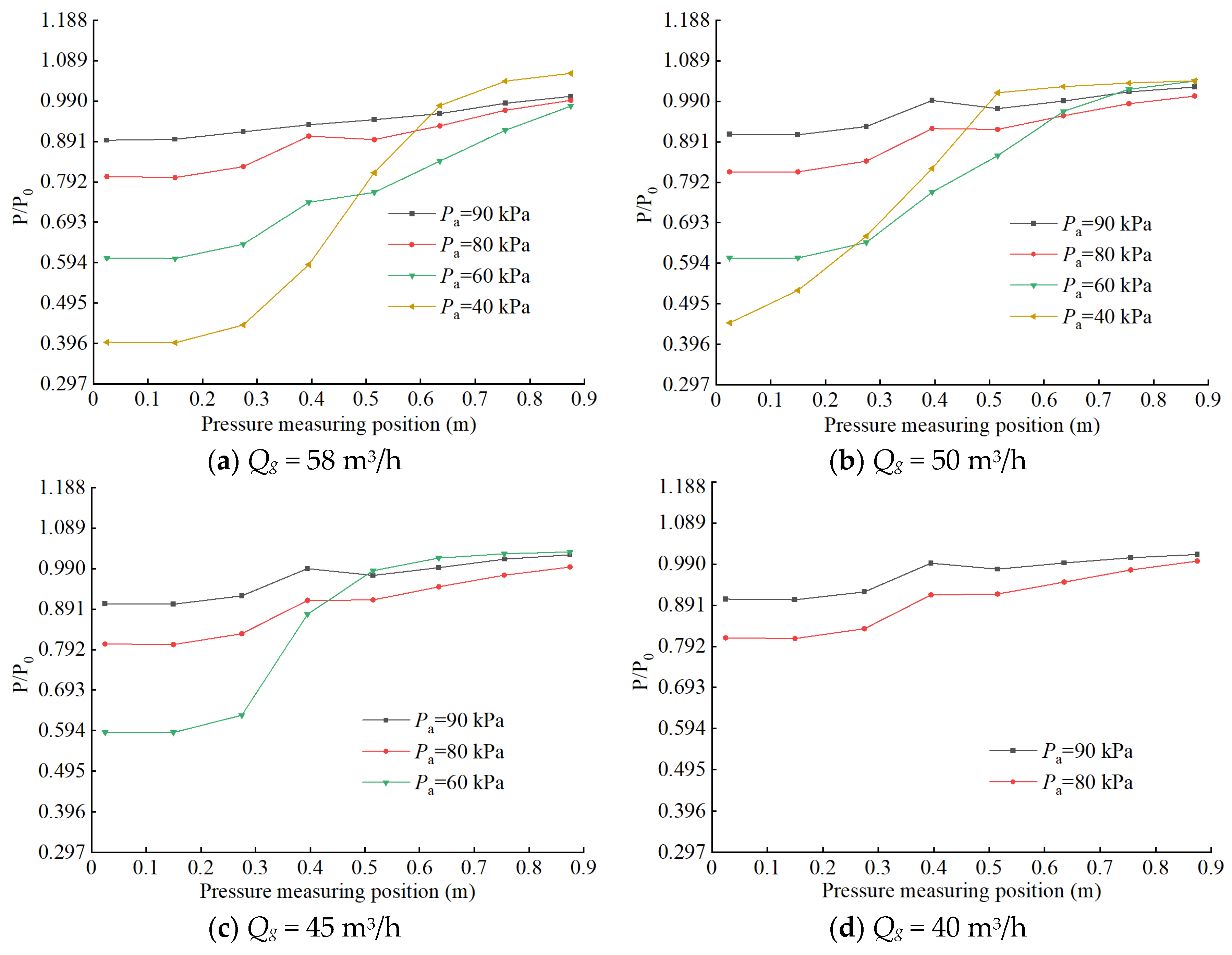
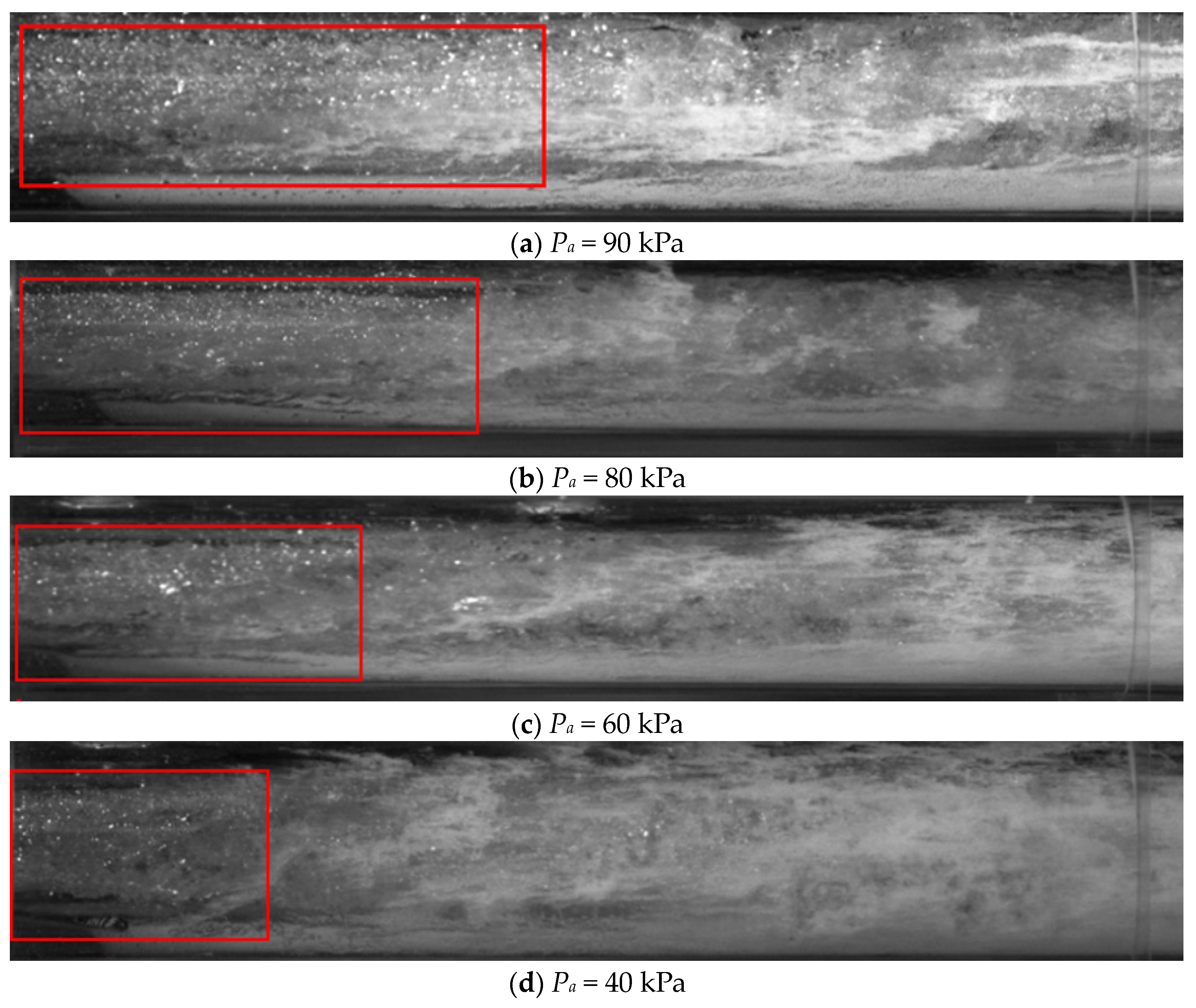
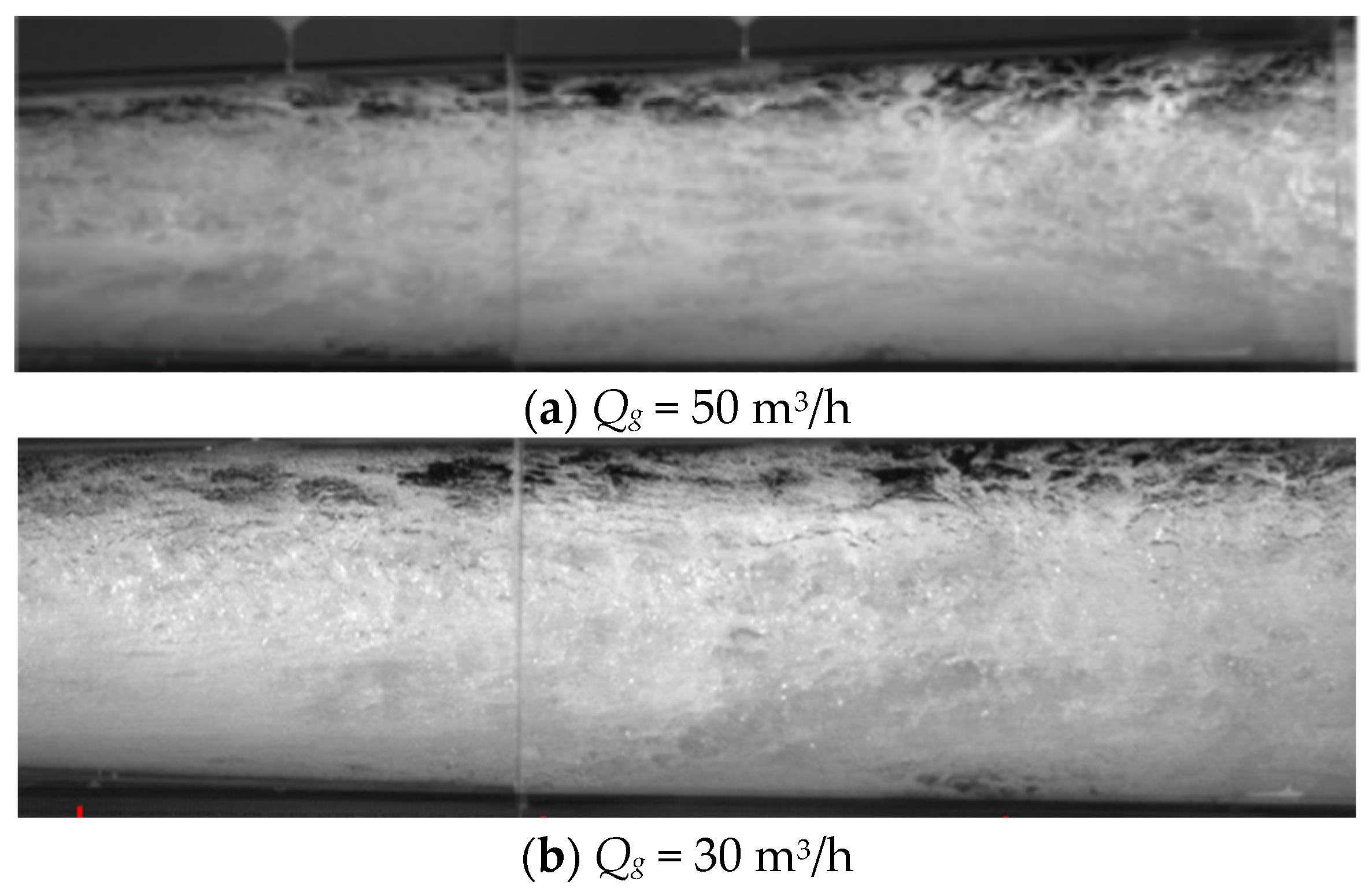
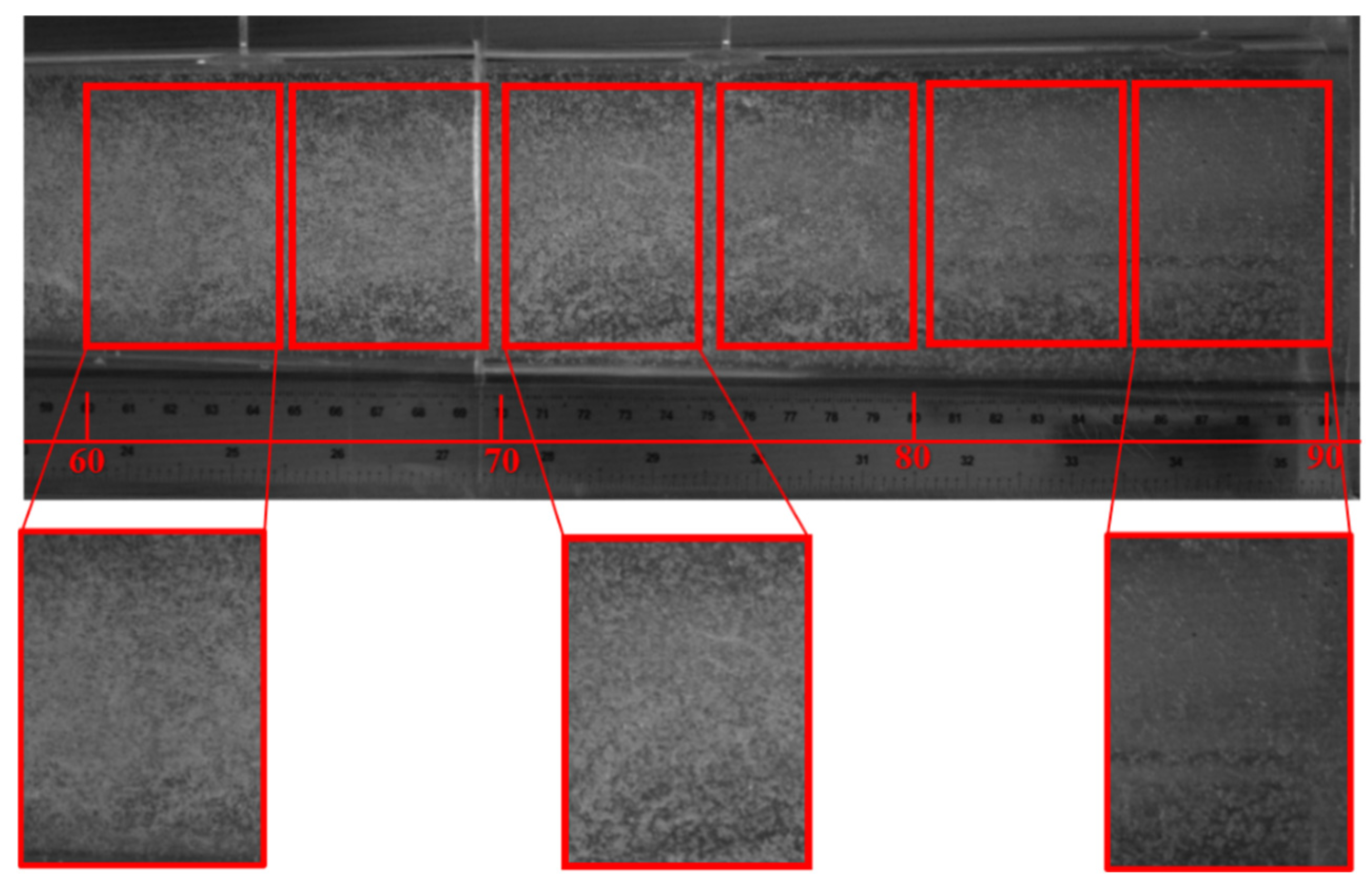
The length of the phase of liquid–gas relative movement in the throat is shortened with the decrease in working water flow rate and with the decrease in inlet pressure, which further leads to the decrease in pumped gas volume. The higher the degree of mixing of liquid and gas phases in the diffusion tube, the more uniform the distribution of foam flow, and the higher the working efficiency of the liquid–gas jet vacuum pump.
(4)
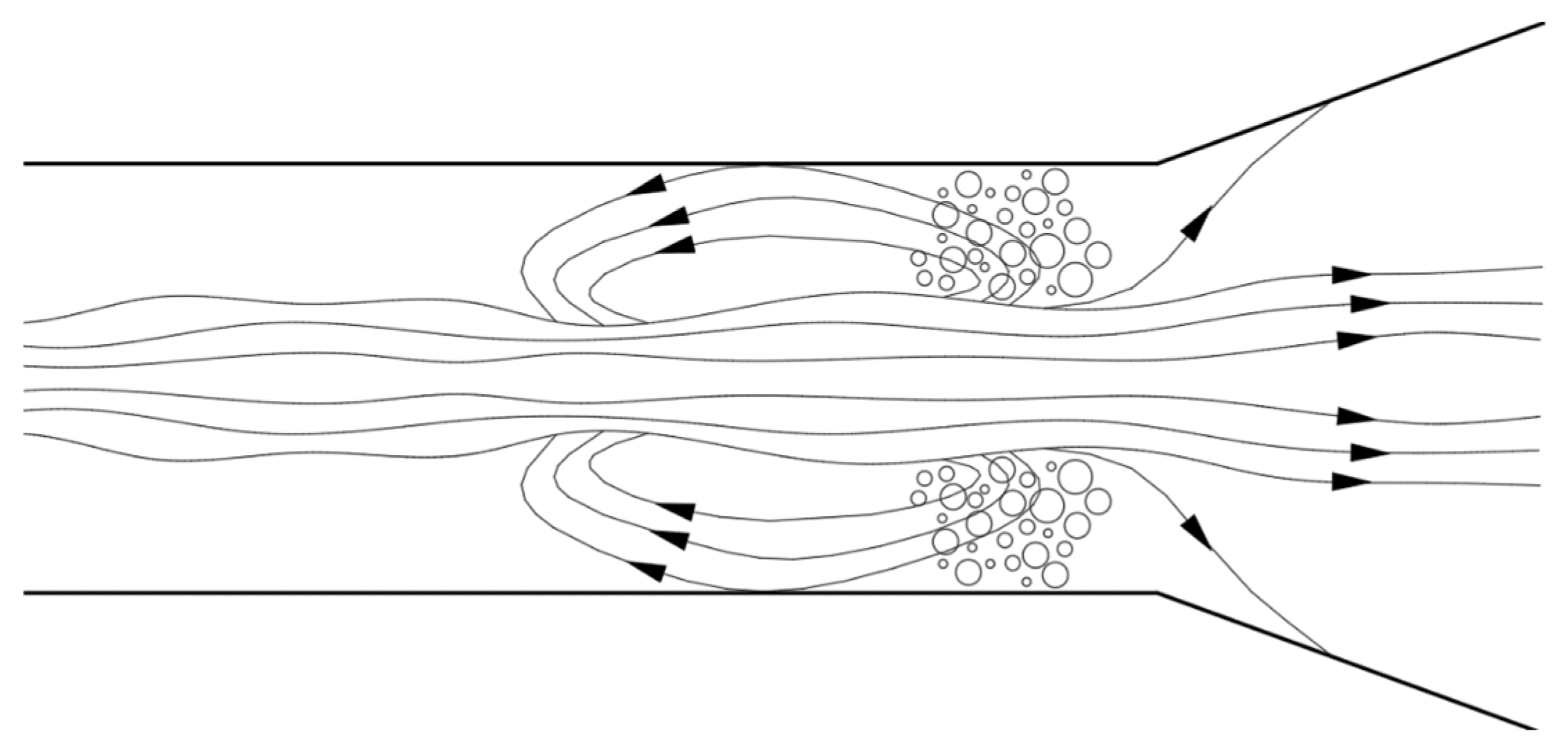
In the extreme vacuum working conditions, the LGJP throat liquid–gas relative movement stage length is extremely short, there is a large number of droplets in the throat after the section of violent reflux, and there is no bubble flow movement stage. There are very few bubbles in the diffusion tube, the bubble diameter along the axis of the movement is gradually reduced, and the number of bubbles is also reduced accordingly.

Author Contributions

Conceptualization, X.Y.; Methodology, X.Y., K.F., X.Z. and J.M.; Software, Q.Z., K.F. and X.Z.; Formal analysis, X.Y. and X.X.; Investigation, X.Y.; Data curation, Z.C. and D.Z.; Writing—original draft, Z.C., X.Y., C.Z., D.Z., Q.Z. and J.M.; Writing—review & editing, X.X.; Visualization, X.X. and C.Z. All authors have read and agreed to the published version of the manuscript.

Funding

This research was supported by Zhejiang Provincial Natural Science Foundation of China under Grant No. LQ24E090003.

Data Availability Statement

No data was used for the research described in the article.

Conflicts of Interest

Author Xu Xiao was employed by the company Shimge Pump Industry (Zhejiang) Co., Ltd. The remaining authors declare that the research was conducted in the absence of any commercial or financial relationships that could be construed as a potential conflict of interest.

References

  1. Li, C.; Zhao, G.; Zhao, Y.; Fu, W.; Zheng, Z. Research on hydraulic loss of liquid ring vacuum pump and optimization of shell profile for high efficiency and energy saving. Vacuum 2023, 207, 111633. [Google Scholar] [CrossRef]
  2. Zhang, D.; Liu, Y.; Kang, J.; Zhang, Y.; Meng, F. The effect of discharge areas on the operational performance of a liquid-ring vacuum pump: Numerical simulation and experimental verification. Vacuum 2022, 206, 111425. [Google Scholar] [CrossRef]
  3. Gao, C. Theory and Test of Pulsed Liquid Jet Pump Technology; China Water Conservancy and Hydropower Press: Beijing, China, 2009. [Google Scholar]
  4. Huang, F.; Hu, B.; Zuo, W.Q.; Li, S. Experiments on the impact force characteristics of high-pressure water jets with different nozzle shapes. J. Chongqing Univ. 2019, 42, 124–133. [Google Scholar]
  5. Wu, Z.; Wang, Y.; Zhang, S.; Lv, L.; Wang, W. Numerical simulation of cavitation performance of nozzles of different shapes. Fluid Mach. 2020, 48, 36–41. [Google Scholar]
  6. Hua, L.; Li, H.; Jiang, Y.; Qin, L. Experimental study on the performance of low and medium pressure spray droplets with square nozzles. J. Irrig. Drain. 2022, 41, 104–109. [Google Scholar]
  7. Li, Y.; He, X.; Yu, W. Experimental study of the effect of nozzle structure on unsteady jet thrusts. Fluid Mach. 2023, 51, 1–6. [Google Scholar]
  8. Xu, M.; Long, X.; Yang, X.; Wu, W.; Wang, X.; Wang, X. Effect of nozzle position on the performance of a new annular jet pump. J. Irrig. Drain. Mach. Eng. 2014, 32, 563–566. [Google Scholar]
  9. Zhang, J.M.; Gan, Z.Y. The effect of a novel nozzle structure on small-scale jets. Laser Technol. 2024, 2, 1–10. [Google Scholar]
  10. Chen, W.; Fan, W.; Zhang, Q.; Peng, C.; Yuan, C.; Yan, C. Experimental Investigation of Nozzle Effects on Thrust and Inlet Pressure of an Air-breathing Pulse Detonation Engine. Chin. J. Aeronaut. 2012, 3, 381–387. [Google Scholar] [CrossRef]
  11. Fu, W.; Li, Y.; Liu, Z.; Wu, H.; Wu, T. Numerical study for the influences of primary nozzle on steam ejector performance. Appl. Therm. Eng. 2016, 106, 1148–1156. [Google Scholar] [CrossRef]
  12. Yun, Q.; Xiang, Q.; Li, H. Experimental study on the performance of several liquid-gas jet pumps with shaped nozzle ejection. Fluid Mach. 2011, 39, 1–16. [Google Scholar]
  13. Gao, G.; Ling, Y.; Wang, Y. Numerical study of the effect of contraction half angle of throat nozzle section on the flow field characteristics of liquid-gas jet pumps. J. Vac. Sci. Technol. 2020, 40, 174–179. [Google Scholar]
  14. Isataev, M.S.; Toleuov, G.; Sultan, M. Experimental Investigation of a Free Turbulent Air Jet Outflowing from a Nozzle of Square Shape. J. Eng. Phys. Thermophys. 2020, 93, 172–177. [Google Scholar] [CrossRef]
  15. Busov, K.A.; Mazheiko, N.A. Boiling of a Jet of Superheated Water with Outlet through a Nozzle with a Square Section. High Temp. 2021, 59, 433–437. [Google Scholar] [CrossRef]
  16. Muvvala, P.; Balaji, C.; Venkateshan, S.P. Experimental investigation on the effect of wire mesh at the nozzle exit on heat transfer from impinging square jets. Exp. Therm. Fluid Sci. 2017, 84, 78–89. [Google Scholar] [CrossRef]
  17. Witte, J.H. Mixing Shocks and Their Influence on the Design of Liquid-Gas Ejectors. Ph.D. Thesis, TU Delft, Delft, The Netherlands, 1962. [Google Scholar]
  18. Liao, D.; Lu, H. Study on the basic performance of liquid-liquid-gas jet pump and each correction factor. Hydrodyn. Res. Prog. 1996, 11, 610–617. [Google Scholar]
  19. Zhang, H.; Zou, D.; Yang, X.; Mou, J.; Zhou, Q.; Xu, M. Liquid-Gas Jet Pump: A Review. Energies 2022, 15, 6978. [Google Scholar] [CrossRef]
  20. Ge, Q. Establishment of Mathematical Model of Liquid-Gas Jet Pump and Its Numerical Simulation Study. Master’s Thesis, Dalian Jiaotong University, Dalian, China, 2012. [Google Scholar]
  21. Ge, Y.J.; Ge, Q.; Yang, J. Numerical simulation of throat-to-nozzle distance and determination of its optimal range for liquid-gas jet pump. Fluid Mach. 2012, 40, 21–24. [Google Scholar]
  22. Xing, R. Liquid-Gas Two-Phase Jet Pump for Non-Condensable Gas Extraction 3D Simulation Study. Master’s Thesis, Shandong University, Jinan, China, 2020. [Google Scholar]
  23. Zhou, Q.; Zhu, C.; Yang, X.; Chen, J.; Mou, J. Flow Channel Optimization to Improve the Performance of a Liquid-gas Ejector for an Intelligent Toilet Spray Bar. Atmosphere 2024, 15, 58. [Google Scholar]
  24. Chen, W. Study and Design Optimisation of Suction Characteristics of Liquid-Gas Jet Pump Based on CFD Simulation. Master’s Thesis, Northeastern University, Shenyang, China, 2014. [Google Scholar]
  25. Bonnington, S.T.; King, A.L. Jet Pumps and Ejectors—A State of the Art Review and Bibliography; Fluid Engineering: London, UK, 1972. [Google Scholar]
  26. Gebouský, O.; Mařík, K.; Haidl, J.; Zednikova, M. Enhancement of gas entrainment rate in liquid-gas ejector pump. Chem. Eng. Res. Des. 2023, 189, 117–125. [Google Scholar] [CrossRef]
  27. Cunningham, R.G. Liquid jet pumps for two-phase flows. J. Fluids Eng. 1995, 117, 309–316. [Google Scholar] [CrossRef]
  28. Gao, C.; Wang, Y.; Chen, H.; Lei, T.; Chen, X.; Wang, X. Experiments on the basic performance of pulsed liquid-gas jet pumps. Nucl. Power Eng. 2010, 31, 133–137. [Google Scholar]
  29. Xiang, Q.; Wang, C.; Wu, Y.; Li, H. Experimental study on the flow inside the diffusion tube of a liquid-gas jet pump. J. Irrig. Drain. Mach. Eng. 2014, 32, 558–562. [Google Scholar]
  30. Xu, X.; Mou, J.; Zhang, H.; Zou, D.; Yang, X.; Liu, X.; Qiu, Z.; Dong, B. Experimental Study on Performance of Liquid-Gas Jet Pump with Square Nozzle. Energies 2023, 16, 7951. [Google Scholar] [CrossRef]
  31. Kumar, R.S.; Mani, A.; Kumaraswamy, S. Analysis of a jet-pump-assisted vacuum desalination system using power plant waste heat. Desalination 2005, 179, 345–354. [Google Scholar] [CrossRef]
  32. Wang, Y.L. Study on Characteristics of Liquid Gas Jet Pump. Master’s Thesis, Taiyuan University of Technology, Taiyuan, China, 2015. [Google Scholar]
  33. Xiang, Q.J.; Yun, Q.L.; Li, H. Experiment Study on Hydraulic Performance of Liquid Jet Gas Pump with Wide Range of Area Ratio. Fluid Mach. 2012, 40, 1–5. [Google Scholar]
  34. Wei, X.; Zhang, R. The axial tip clearance leakage analysis of the winglet and composite blade tip for the liquid-ring vacuum pump. Vacuum 2022, 200, 111027. [Google Scholar] [CrossRef]
Figure 1. Pressure and velocity change curve during the jetting process.
Water 16 02358 g001
Figure 2. Liquid–gas jet pump experimental bench and camera position erection. 1—drainage outlet, 2—high-level spillway, 3—make-up valve, 4—inlet valve, 5—float flowmeter, 6—electromagnetic flowmeter, 7—centrifugal pump top water control valve, 8—centrifugal pump, 9—centrifugal pump inlet valve, 10—baffle, 11—circulating water tank, 12—LGJP, 13—high-brightness searchlight, 14—high-speed camera.
Water 16 02358 g002
Figure 3. LGJP experimental device real view (1 to 8 are pressure transmitters).
Water 16 02358 g003
Figure 4. The geometry of the square-nozzle LGJP.
Water 16 02358 g004
Figure 5. Effect of inlet pressure on pumping volume ratio (a) and operating efficiency (b).
Water 16 02358 g005
Figure 6. Effect of working water flow rate on pumping volume ratio (a) and working efficiency (b).
Water 16 02358 g006
Figure 7. Effect of working water flow rate on ultimate vacuum pressure.
Water 16 02358 g007
Figure 8. Effect of inlet pressure on pressure in the throat and diffusion tube.
Water 16 02358 g008
Figure 9. Variation and effect of inlet pressure on liquid–gas two-phase flow pattern (Qg = 58 m3/h).
Water 16 02358 g009
Figure 10. Lengths of phases of relative liquid–gas motion in the throat at different inlet pressures.
Water 16 02358 g010
Figure 11. Changes of mixed flow regimes in diffusion tubes at different inlet pressures.
Water 16 02358 g011
Figure 12. Effect of working water flow on the pressure in the throat and diffusion tube.
Water 16 02358 g012
Figure 13. Changes and effects of working water flow rate on the liquid–gas two-phase flow pattern in the pipe.
Water 16 02358 g013
Figure 14. Lengths of phases of liquid–gas relative motion in the throat at different working water flow rates.
Water 16 02358 g014
Figure 15. Changes of flow pattern in diffusion tubes under different working water flow rates.
Water 16 02358 g015
Figure 16. Pressure variations in ultimate vacuum pipes and diffusion tubes at different working water flow rates.
Water 16 02358 g016
Figure 17. Changes in flow regime in the pipe during ultimate vacuum extraction.
Water 16 02358 g017
Figure 18. Schematic diagram of throat backflow during ultimate vacuum pumping.
Water 16 02358 g018
Figure 19. Bubble change in diffusion tube during evacuation.
Water 16 02358 g019
Figure 20. Volume distribution of bubbles in the diffusion tube during ultimate vacuum pumping.
Water 16 02358 g020
Disclaimer/Publisher’s Note: The statements, opinions and data contained in all publications are solely those of the individual author(s) and contributor(s) and not of MDPI and/or the editor(s). MDPI and/or the editor(s) disclaim responsibility for any injury to people or property resulting from any ideas, methods, instructions or products referred to in the content.

