Article

Optimizing Trapezoidal Labyrinth Weir Design for Enhanced Scour Mitigation in Straight Channels

1
Irrigation and Hydraulics Department, Faculty of Engineering, Cairo University, Giza 12316, Egypt
2
Civil Engineering Department, Faculty of Engineering Materia, Helwan University, Cairo 11795, Egypt
3
Pyramids Higher Institute for Engineering and Technology, Giza 12578, Egypt
4
Civil Engineering Department, Faculty of Engineering-Shoubra, Benha University, Cairo 11629, Egypt
*
Author to whom correspondence should be addressed.
Water 2024, 16(17), 2443; https://doi.org/10.3390/w16172443 (registering DOI)
Submission received: 1 August 2024 / Revised: 23 August 2024 / Accepted: 27 August 2024 / Published: 29 August 2024
(This article belongs to the Section Hydraulics and Hydrodynamics)

Abstract

:
Designing hydraulic structures requires careful consideration of local scouring downstream. This study investigated the performance of trapezoidal labyrinth weirs in controlling flow and mitigating scour in straight channels through physical model experiments. Sixty configurations were examined, using weir apex angles of 20°, 45°, 60°, and 80°, heights of 30 cm, 35 cm, and 40 cm, and flow rates of 50–200 L/s. A linear weir served as a reference. The results showed that the 60° apex angle consistently outperformed other configurations, reducing scour depth by up to 41% and scour length by up to 50% compared to the linear weir. It also decreased deposition depth by 40% and length by 50%. Lowering weir height from 40 cm to 30 cm led to reductions of 35% in scour depth and 40% in scour length at low discharges. These improvements remained significant even at higher flow rates, with a 29% reduction in scour depth and 25% in scour length at 200 L/s. This study provides evidence-based recommendations for optimizing labyrinth weir designs to define the relationship between hydraulic efficiency and erosion control. It offers valuable insights into weir geometry, flow conditions, and the resulting scour and deposition patterns. These findings contribute to the optimization of labyrinth weir designs to minimize downstream bed configurations. The tests were conducted under limited flow conditions.

1. Introduction

Water is an essential resource for both life and the advancement of civilization. Therefore, finding creative ways to manage, distribute, and conserve it is always necessary. The importance of innovative hydraulic infrastructures to safeguard and optimize these resources is increased by the escalating issues of population growth, urban development, and climate change [1]. Sustainable development requires the effective management of water resources, particularly in the current environment, with unpredictable climate fluctuations, deteriorating environmental conditions, and growing worldwide water demands [2]. Labyrinth weirs are an innovative approach, which has gained considerable attention in hydraulic engineering due to their unique design features and enhanced performance in controlling flow and mitigating scour in straight channels. These structures, characterized by a non-linear crest shape, offer several advantages over traditional linear weirs, particularly in terms of flow regulation and sediment management [3].
It was proven that the flow over a skew weir is strongly influenced by the angle the weir forms with the upstream flow direction [4]. One of the primary advantages of labyrinth weirs is their ability to optimize flow control by extending the crest length within the same width as a linear weir [5,6]. This extended crest length allows for increased discharge capacity and improved efficiency in regulating flow rates, thereby reducing the risk of flooding and enhancing water management in hydraulic systems [7,8]. Furthermore, experimental studies have found that adding an additional cycle along the lateral crest of trapezoidal labyrinth weirs, which are crucial hydraulic structures for water flow control and management, can further enhance these systems’ efficiency and overall performance [9]. In addition to flow control, labyrinth weirs play a crucial role in mitigating scouring downstream of hydraulic structures. Scour, the erosion of sediment from the bed and banks of water channels, presents a significant challenge due to its potential to weaken the stability of structures, which leads to costly maintenance and repair [10,11]. This local scouring downstream of hydraulic structures stands as a critical concern, significantly impacting their safety and stability.
As water flows over the labyrinth weir, it undergoes complex hydrodynamic processes, including contraction, acceleration, and turbulence, leading to significant energy dissipation downstream [12]. One critical aspect of labyrinth weir design is the assessment of scour parameters, which govern the potential for scouring and deposition of the downstream channel bed and apron. Excessive scouring can undermine the structural integrity of the weir, lead to downstream erosion, and potentially cause failure, posing risks to infrastructure and public safety [13]. Labyrinth weirs are specifically designed to minimize scour by promoting flow stabilization and reducing turbulence downstream of the weir crest [14]. Furthermore, the complex geometry of labyrinth weirs creates multiple flow paths and vortices, which help to dissipate energy and reduce the erosive effects of flowing water. This ability to dissipate energy makes labyrinth weirs particularly effective in controlling scour and maintaining channel stability in straight channels [15].
Numerous studies have investigated the influence of various geometric and hydraulic parameters on the hydraulic performance and scour potential of downstream labyrinth weirs. Researchers have studied several factors, such as weir height, crest length, cycle geometry, and flow conditions [16,17,18].
Elnikhely et al. [19] carried out experimental studies to investigate, at varying flow velocities, the local scouring downstream of a triangular labyrinth weir and demonstrated a decrease in several scour and deposition parameters at all weir apex angles using varying apex angles. When compared to a linear weir, an ideal weir apex angle of 60° can decrease scour parameters while increasing energy losses. Yasi et al. [20] investigated the progression of scour holes over time under three different free-flow scenarios until reaching a stable bed state. Initial findings suggested that the curved planform demonstrates superior efficiency in terms of flow capacity. The results showed that the depth and extent of scouring downstream of the standard weir and the trapezoidal labyrinth design are higher compared to the other two labyrinth configurations. The effectiveness of the triangular and curved designs differs depending on the hydraulic head conditions. Ikinciogullari et al. [21] compared local scour patterns downstream of triangular, trapezoidal, and labyrinth weirs under free overfall conditions. They found that labyrinth weirs significantly surpassed classical weir designs in terms of scour mitigation. Specifically, labyrinth weirs produced less severe local scour and exhibited a shorter horizontal distance to the point of maximum scour depth compared to their triangular and trapezoidal counterparts. These findings suggest that labyrinth weirs provide improved structural safety and reduced erosion risk in hydraulic applications, potentially influencing future weir design choices for enhanced downstream bed protection. Dehghani et al. [22] investigated the impact of upstream sedimentation levels and downstream bed levels on the discharge coefficients of trapezoidal labyrinth weirs with different geometries. The analysis of the results revealed that altering the tailwater level to two-thirds of weir height altered the flow pattern of the falling nappe and led to significant changes in the discharge coefficients of the weirs, particularly during high-flow discharges.
Obaida et al. [23] investigated the effects of solid aprons of varying lengths on scour reduction downstream of a sharp-crested weir in an open-channel flow. The research found that an optimal apron length significantly reduced scour depth and length, while shorter or longer aprons were less effective due to turbulence and vortex formation. Empirical equations were developed to predict scour dimensions, providing valuable insights for designing hydraulic structures with improved stability and scour mitigation.
Guan et al. [24] presented an experimental study investigating local scour at submerged weirs in sand-bed channels, considering the effects of sediment size and tailwater depth. New equations were proposed for predicting equilibrium scour depths upstream and downstream of the submerged weir, accounting for factors such as sediment size, tailwater depth, flow intensity, and weir height. The study found that decreasing sediment size reduces downstream scour depth, while decreasing tailwater depth increases downstream scour. They provided a new technique for estimating the maximum scour depths at the weir based on the experimental findings. Fathi et al. [25] proved that altering the design of piano key weirs, particularly by adding steps, effectively reduced scour depth compared to non-stepped weirs. They found that factors such as discharge rates, tailwater depth, and bed material size significantly influence scour dimensions. These findings emphasize the importance of careful weir design in controlling scouring and enhancing the stability of hydraulic structures.
Guan et al. [26] investigated the scour development downstream of submerged weirs, revealing that scour holes form rapidly in the initial stages and gradually slow down as they reach equilibrium. Increased flow intensity and overtopping ratios led to larger scour depths and volumes. They also developed empirical equations to predict the temporal evolution of scour dimensions, providing valuable tools for hydraulic engineers to estimate and mitigate scour in riverine and coastal environments. Abdi et al. [27] examined the evolution of scour parameters downstream of a trapezoidal piano key weir, showing that, as the Froude number and relative vertical distance increased, the scour rate, depth, area, and volume also increased, particularly in the early stages of testing. Most of the scouring occurred within the first 20% of the test duration, highlighting that initial conditions play a crucial role. The study also developed predictive equations for scour behavior, providing useful tools for future hydraulic design and analysis.
From the review above, it is noted that few studies were performed taking into account the hydraulic design of the trapezoidal labyrinth weir and its performance on the downstream bed configurations, expressed in terms of the geometry of local scour and deposition. Consequently, initiating the current study requires examining the focal parameters involved in trapezoidal labyrinth weir design under several hydraulic conditions. Similar tests are also carried out by implementing a sharp classical weir to explore the superiority of the labyrinth weir and the optimum design regarding weir height and apex angles under limited flow conditions.
This paper is organized as follows: Section 2 presents the experimental setup and methodology, including the description of the physical model used and the parameters measured, justifications for the assumptions, and finally, the dimensional analysis. Section 3 details the experimental results, analyzing the impact of different apex angles and weir heights on the developed bed’s morphological changes under various flow conditions. It also contains a discussion about the findings, comparing the performance of different weir geometries.

2. Materials and Methods
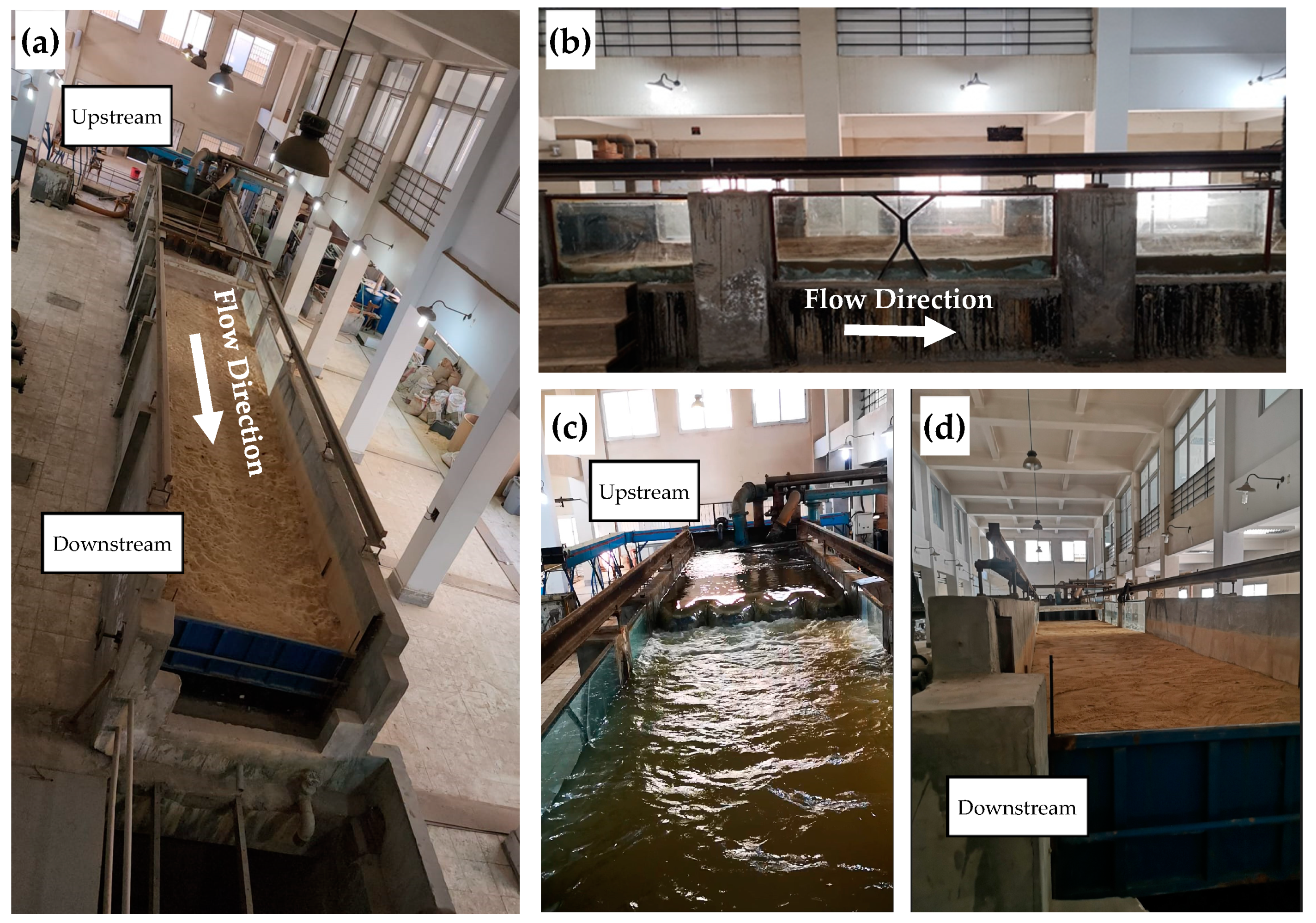
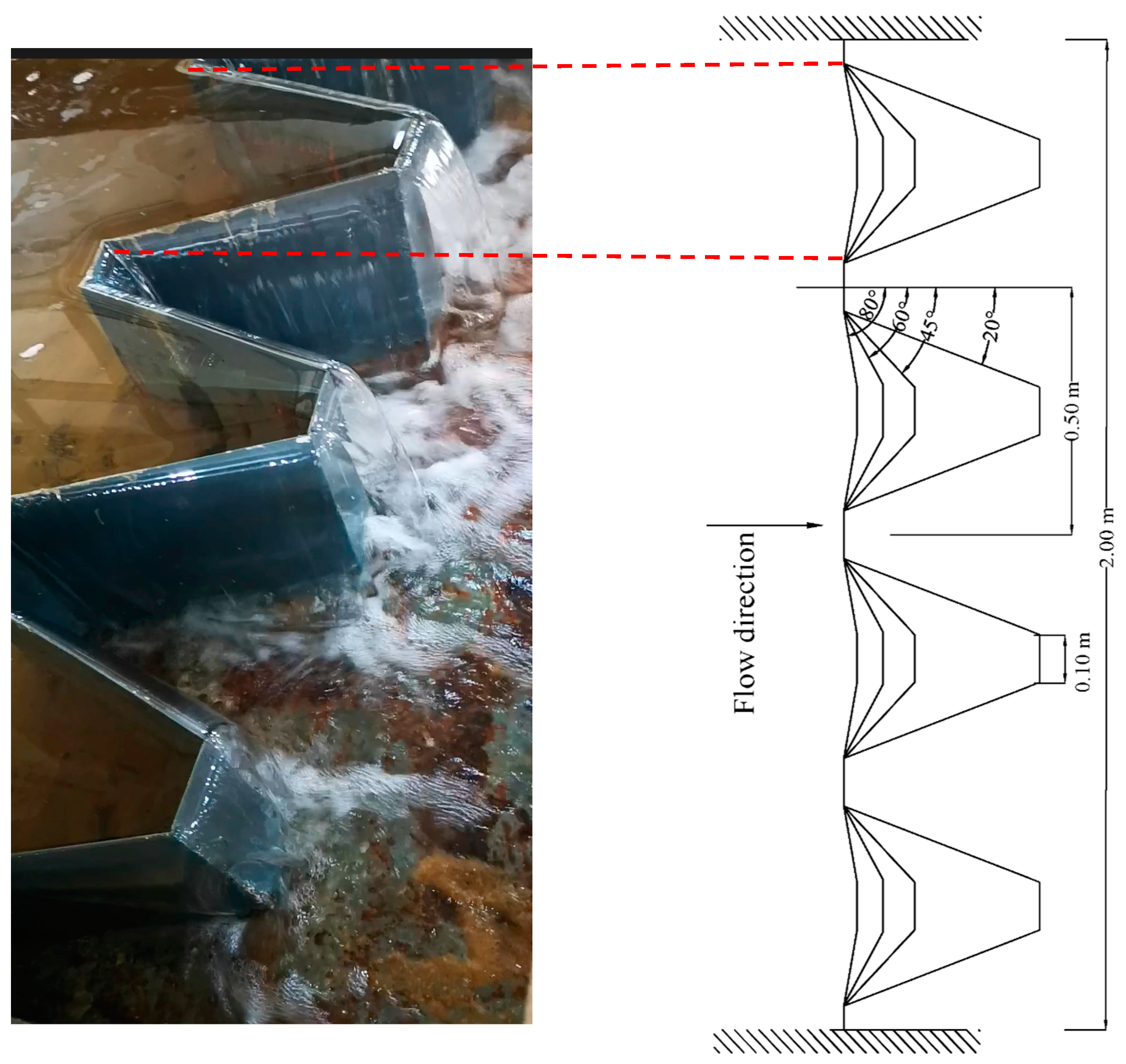
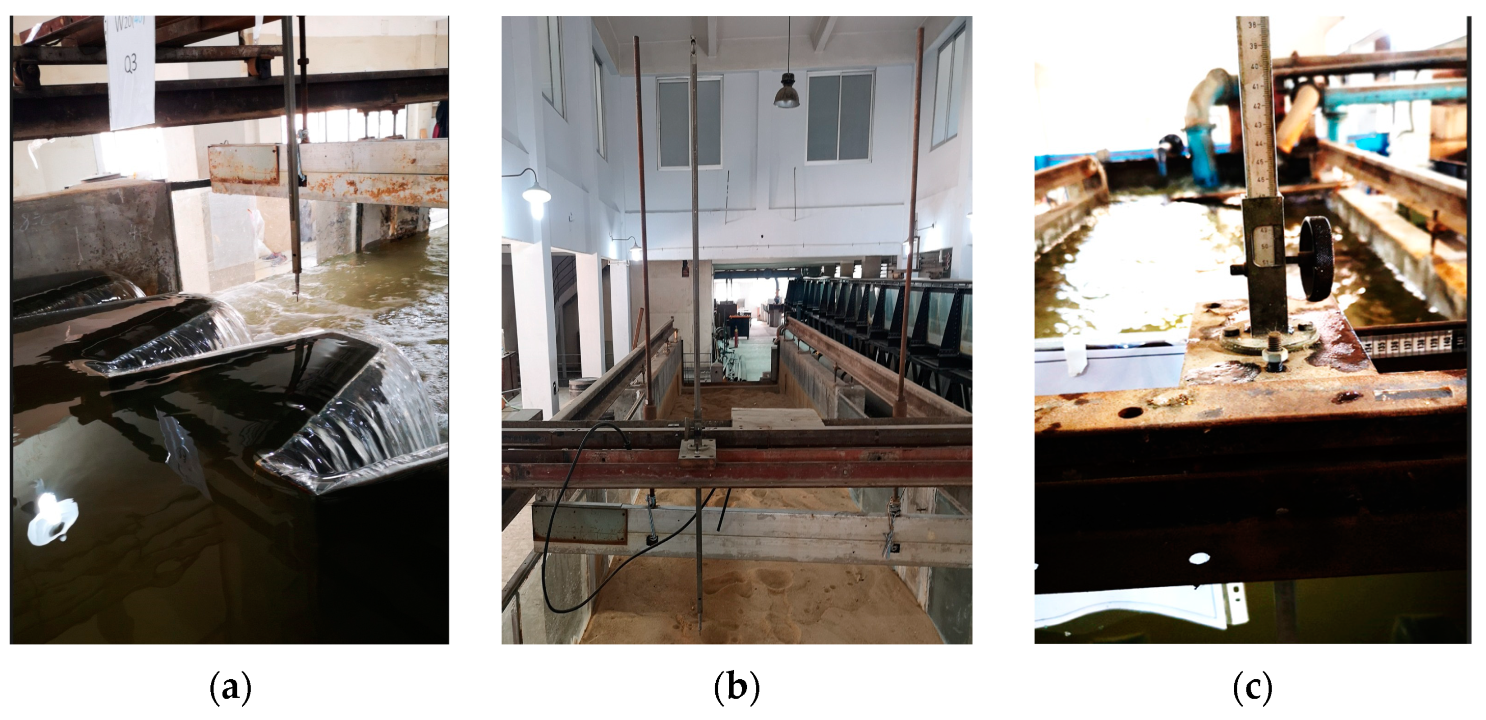
2.1. Model Setup

The present study was carried out using a physical model in the Irrigation and Hydraulics Laboratory at Cairo University. The flume was 20.5 m long, 2 m wide, and had a depth of 85 cm. The channel had a flat longitudinal slope, with a concrete bed. The sides were made of glass supported by steel frames, providing visualization for the flow patterns and their interaction with the sand bed. The bed was leveled to a depth of 20 cm on the channel’s bed, as shown in Figure 1 and Figure 2. Figure 1 also shows a plan view of the physical model, showing its entrance at the upstream and its outlet at the downstream. Figure 2 shows the schematic diagram for the model from its side view and its plan. The flume walls were constructed to be smooth to minimize boundary effects and ensure uniform flow conditions. Water was delivered from the ground sump to the head tank using a pump at the upstream of the model. The discharge in the flume was measured using an electronic flowmeter with high accuracy ±1%. The tail gate was employed downstream of the channel to adjust the water depth in the downstream.
A steel-made 0.5 mm thick trapezoidal labyrinth weir was implemented as a heading structure within the flume. The weir structure incorporated four of trapezoidal crests arranged in cycles (N = 4). The apex angles of the trapezoidal crests were varied to investigate their impact, with distinct angles of 20°, 45°, 60°, and 80°, as represented in Figure 3. The weir crest height (P) was adjustable, with three different heights (40, 35, and 30 cm), allowing for investigations at different upstream water levels and flow conditions.
The total length of the weir structure along the flume was 2.0 m, with the central portion spanning 0.50 m. The side trapezoidal crests were symmetrically implemented on either side. The weir crest height (P) was adjustable according to the given scenario, from 40 cm to 35 cm to 30 cm, allowing for investigations at different upstream water levels and flow conditions. This model setup aimed to study the flow characteristics and the potential for downstream scour and deposition associated with trapezoidal labyrinth weirs of varying geometries. Special emphasis was placed on the influence of the apex angle on these parameters. A concrete apron, 2.5 m in length, was installed downstream of the weir to prevent direct deformations caused by water action.
The experiments involved monitoring various scour parameters downstream of the trapezoidal labyrinth weir. A sieve analysis was conducted to define the grain size distribution of the mobile bed material (d50 = 0.3 mm), as illustrated in Figure 4. Before starting the experiment, the soil level was adjusted to match the level of the concrete apron surface. A linear crest weir was also incorporated to act as a reference case to assess the impact of using the trapezoidal labyrinth weir on scour parameters. All tests were conducted over fixed runtime duration of 4 h, which was determined from several trial tests during which the quasi-equilibrium state was reached under a maximum running discharge of 200 L/s. This duration allowed for the observation of the development of scour and deposition and ensured the cessation of their processing and the immobility of the sediment particles, with no significant change in scour hole dimensions noted beyond this time. Each experiment set applied four different flow discharges, Q = 50, 100, 150, and 200 L/s. In the test program, the tailwater depth was fixed at 20 cm to maintain a certain condition at the toe end of the hydraulic structure. A calibrated point gauge with an accuracy of ±0.1 mm was used for the level measurements of water levels or bed levels, as shown in Figure 5.

2.2. Justification of Experimental Parameters and Assumptions

The selection of experimental parameters in this study was based on preliminary trials and the careful consideration of practical and scientific factors. This section outlines the rationale behind the key parameter choices:
  • The weirs were constructed from 5 mm thick metal sheets. This thickness was chosen as an optimal balance between structural integrity and practicality. Thinner sheets (<5 mm) led to deformations, particularly for taller weirs (40 cm) under high discharge. On the other hand, thicker sheets increased costs and posed handling difficulties during installation.
  • The weir heights were selected between 30 and 40 cm. This range was determined after observing that taller weirs caused complete bed material removal under high discharge, while shorter weirs failed to produce noticeable bed configurations under low discharge.
  • The weir apex angles ranged between 20° and 80°. The angles below 20° showed poor energy dissipation performance, while angles exceeding 80° caused the trapezoidal labyrinth weir to behave similarly to a classical sharp-crested weir, negating the benefits of the labyrinth design.
  • Discharges between 50 and 200 L/s were tested. The flows below 50 L/s did not produce significant bed material development for shorter weirs, while discharges exceeding 200 L/s resulted in complete bed material movement, limiting the ability to study the scour patterns.
  • The run time duration was set to 4 h, during which the quasi-equilibrium state was reached, and no further appreciable bed movement was recorded. Consequently, extending the run time duration beyond this period was useless with respect to bed configurations.

2.3. Dimensional Analysis

Previous investigations of the scour process at the downstream of trapezoidal labyrinth weirs have demonstrated that the scour and deposition parameters considerably depend on the geometric properties of the weir, upstream flow conditions, and physical properties of the bed material [28,29]. To measure the developed scour/deposition downstream of the concrete apron under various discharge conditions, several key parameters were defined. These parameters included Ds, the maximum scour depth (cm); Ls, the scour length, which is defined as the distance from the end of the apron to the location of the maximum scour hole (cm); Dd, the maximum deposition depth (cm); Ld, the maximum deposition length, which is the distance from the end of the apron to the location of the maximum sand deposition (cm); Q, the flow discharge (L/s); P, the weir width; W, the flume width (m); Lb, the length of the concrete apron (m); Yt, the tailwater depth (cm); α, the weir apex angle; g, the gravity acceleration; ρ , the water density; ρ s , the soil particle density; So, the flume bed slope; d50, the median grain size; V, the mean flow velocity; μ, the dynamic water viscosity; σ, the surface tension; N, the total number of weir cycles. The parameters are depicted in Figure 2 and tabulated in Table 1. These measurements are significant for assessing the erosive effects of flowing discharge and understanding the potential risks downstream of the weir.
According to the parameters mentioned, the effective variables governing the morphological changes, presented in terms of maximum local scour depth developed downstream of the trapezoidal labyrinth weir, were as follows:
f P , D s , L s , D d ,   L d , Q ,   W ,   L b ,   y t , α , g ,   ρ , ρ s ,   S o ,   d 50 ,   V ,   μ ,   σ , N = 0
In this study, W, Lb, yt, g, ρ, ρs, So, d50, and N were kept constants throughout the experimental work. Therefore, they can be neglected from Equation (1). The equilibrium time for scour geometry was fixed for all experimental tests. Using the π-theorem and applying the properties of dimensional analysis, it yields,
f P W , D s y t , L s y t , D d y t , L d y t , α , V g y t , ρ Q W μ ,   ρ V 2 B σ ,   = 0
where V g y t is the Froude number, Fr; ρ Q W μ is the Reynolds number, Re; and ρ V 2 B σ is the Weber number, We. Substitute these into Equation (2):
f P W , α , N ,   F r ,   R e ,   W e ,   D s y t ,   L s y t , D d y t , L d y t = 0
D s y t , L s y t , D d y t , L d y t = f P W , α , N ,   F r ,
The key parameters from the laboratory tests, including weir height, apex angle, and flow rates, can be scaled to field conditions using the Froude similitude. This scaling approach maintains the ratio of inertial to gravitational forces, ensuring that the flow dynamics in the laboratory model are representative of those in the prototype.

3. Results and Discussion

Several cases for the trapezoidal labyrinth weir were applied for the experiments in the physical model, with different heights (P) of 30, 35, and 40 cm and with different apex angles of α = 20°, 45°, 60°, and 80°. A sharp-crested linear weir was also used as a reference for the other weir cases. In these tests, different discharges, Q = 50, 100, 150 and 200 L/s, were applied for each different weir case, with a total of 60 distinct investigated configurations. To provide a stable state at the hydraulic structure’s toe end, the tailwater depth was kept constant at 20 cm. After the discharge flow reached equilibrium in the channel, and no changes in bed material were predictable, different scour/deposition parameters were measured for each configuration. The relative scour and deposition parameters, encompassing both depth and length, were quantified, and their relationship with the discharge was graphically represented. The various impacts of changing the apex angle and weir height on the scour and deposition parameters are discussed separately. Additionally, techniques such as using calibrated two-point gauges, shown in Figure 6, are used to provide accurate data on scour/deposition depth and length over time. The water and bed levels across the channel were measured using the point gauge that was mounted on the carriage.

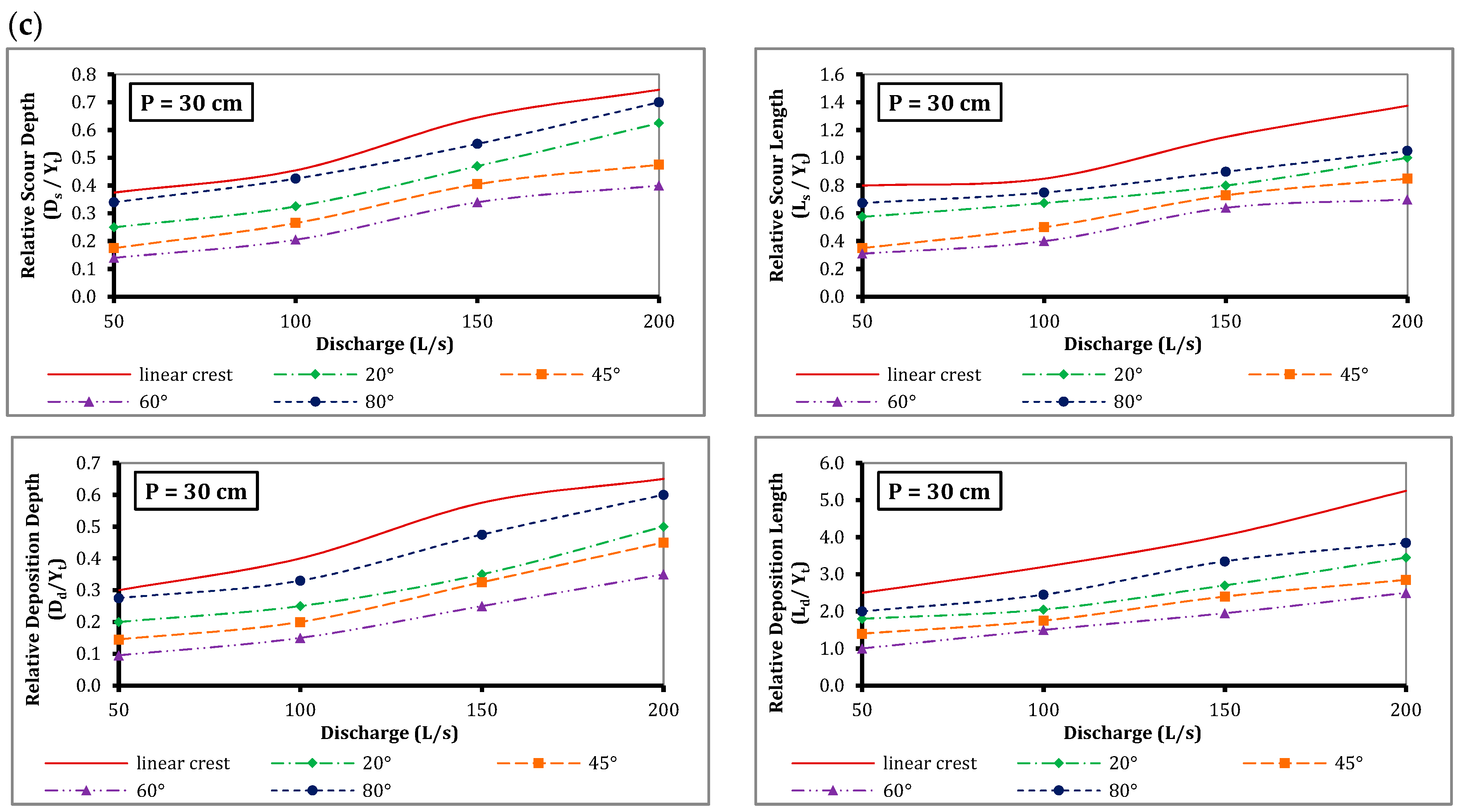
3.1. Effect of Labyrinth Weir Apex Angle on Scour and Deposition Parameters

Results related to the influence of the apex angle α = 20°, 45°, 60°, and 80° on the parameters downstream of the trapezoidal labyrinth weir are shown in this section. The analysis was based on the data and figures provided for a weir height of 40 cm, as well as a comparative analysis of the 35 cm and 30 cm weir heights. When estimating different bed configurations, non-dimensional parameters outperform dimensional ones in terms of performance [30]. Therefore, the relative scour and deposition parameters, Ds/yt, Ls/yt, Dd/yt, and Ld/yt were calculated. First, for the weir height of 40 cm, it was found that the relative scour and deposition parameters increased with increasing discharge for all weir configurations. Among all the apex angles investigated, it was observed that the apex angle α = 60° resulted in lower relative scour and deposition depths and lengths compared to the other apex angles. This trend is consistent across all the tested discharges, as shown in Figure 7a.
This analysis revealed that at α = 60°, lower scour and deposition magnitudes were recorded, indicating a noticeable reduction in the erosive forces and sediment transport capacities downstream of the weir. This behavior can be attributed to the more gradual change in flow direction and the more uniform distribution of flow velocities associated with larger apex angles. After completion of these experiment runs, the height of the trapezoidal labyrinth weir was lowered to 35 cm and the same different discharges were applied to the four different apex angles and the linear crest weir. Later, the weir height was reduced to 30 cm, and all the previous investigations were applied.
Figure 7b shows the relationship between the passing discharge and the scour and deposition parameters for a trapezoidal labyrinth weir of height (P) 35 cm. In addition, compared to the case with a weir height of 40 cm, the scour/deposition parameters are generally lower for the same discharge and apex angle. Figure 7c also illustrates the relationship between the passing discharge and the scour/deposition characteristics for a trapezoidal labyrinth weir with a height (P) of 30 cm.
When comparing the trapezoidal labyrinth weir with an apex angle of 60° to the sharp-crested linear weir, there are several potential improvements and advantages offered by the 60° apex angle configuration. Firstly, the 60° weir has a longer effective crest length compared to the linear weir, which results in higher a discharge capacity for the same upstream head conditions. In addition, the flow in the 60° labyrinth weir undergoes more significant changes in direction and contraction/expansion as it passes through the constricted passages formed by the sidewalls, resulting in increased energy dissipation downstream of the weir, potentially reducing the scouring potential and the need for extensive stilling basins or energy dissipators.
For P = 40 cm, the 60° angle labyrinth weir reduces the scour length by 50% and the scour depth by 41% compared to the linear weir. It also decreases deposition length by 50% and deposition depth by 40%. These substantial reductions are maintained across the 35 cm and 30 cm weir heights, with the 60° angle consistently showing its superiority compared to other labyrinth weir configurations. All labyrinth weir angles showed improvements compared to the linear weir. The 60° angle consistently demonstrated the most significant reductions. The 45° angle followed closely, while the 80° and 20° angles, although better than the linear weir, showed less pronounced improvements. For the 40 cm weir height, the 60° angle demonstrated superior performance in all parameters. It reduced scour depth (Ds/yt) by 33% compared to the 80° angle, 10% compared to the 45° angle, and 23% compared to the 20° angle. Scour length (Ls/yt) was reduced by 36%, 15%, and 27%, respectively. Deposition depth (Dd/yt) showed reductions of 39%, 14%, and 30%, while deposition length (Ld/yt) was reduced by 35%, 17%, and 28% compared to the 80°, 45°, and 20° angles, respectively.
Regarding the 35 cm weir height, the trend continues with the 60° angle being better than the others. The scour depth was reduced by 33%, 10%, and 23%, while the scour length showed reductions of 38%, 14%, and 26% compared to the 80°, 45°, and 20° angles, respectively. On the other hand, the deposition depth was reduced by 42%, 14%, and 30%, and the deposition length by 37%, 16%, and 29%, respectively. Finally, for the 30 cm weir height, the 60° angle’s performance was even more noticeable. The scour depth reductions are 46%, 18%, and 35%, while the scour length was reduced by 39%, 16%, and 33% compared to the 80°, 45°, and 20° angles. Deposition depth showed significant reductions of 50%, 25%, and 35%, and deposition length was reduced by 40%, 17%, and 31%, respectively.
For the tested weir heights, the 60° apex angle outperformed the other angles, with the most substantial improvements seen when compared to the 80° and 20° angles. The improvements are particularly notable in reducing deposition height and scour depth. The 45° angle generally showed the minimum difference from the 60° angle. Therefore, it is suggested as the next best option if a 60° angle is not feasible. These results emphasize the effectiveness and significant advantages of trapezoidal labyrinth weirs with a 60° apex angle in minimizing scour and deposition across various weir heights and flow conditions. This design is the best option for hydraulic structure design when downstream bed protection is a top concern because it performs better than conventional linear weirs in reducing downstream erosion and sediment transport. The 60° apex angle steadily established the best performance, offering significant benefits that make it a preferable option in scenarios requiring effective management of scour and deposition.

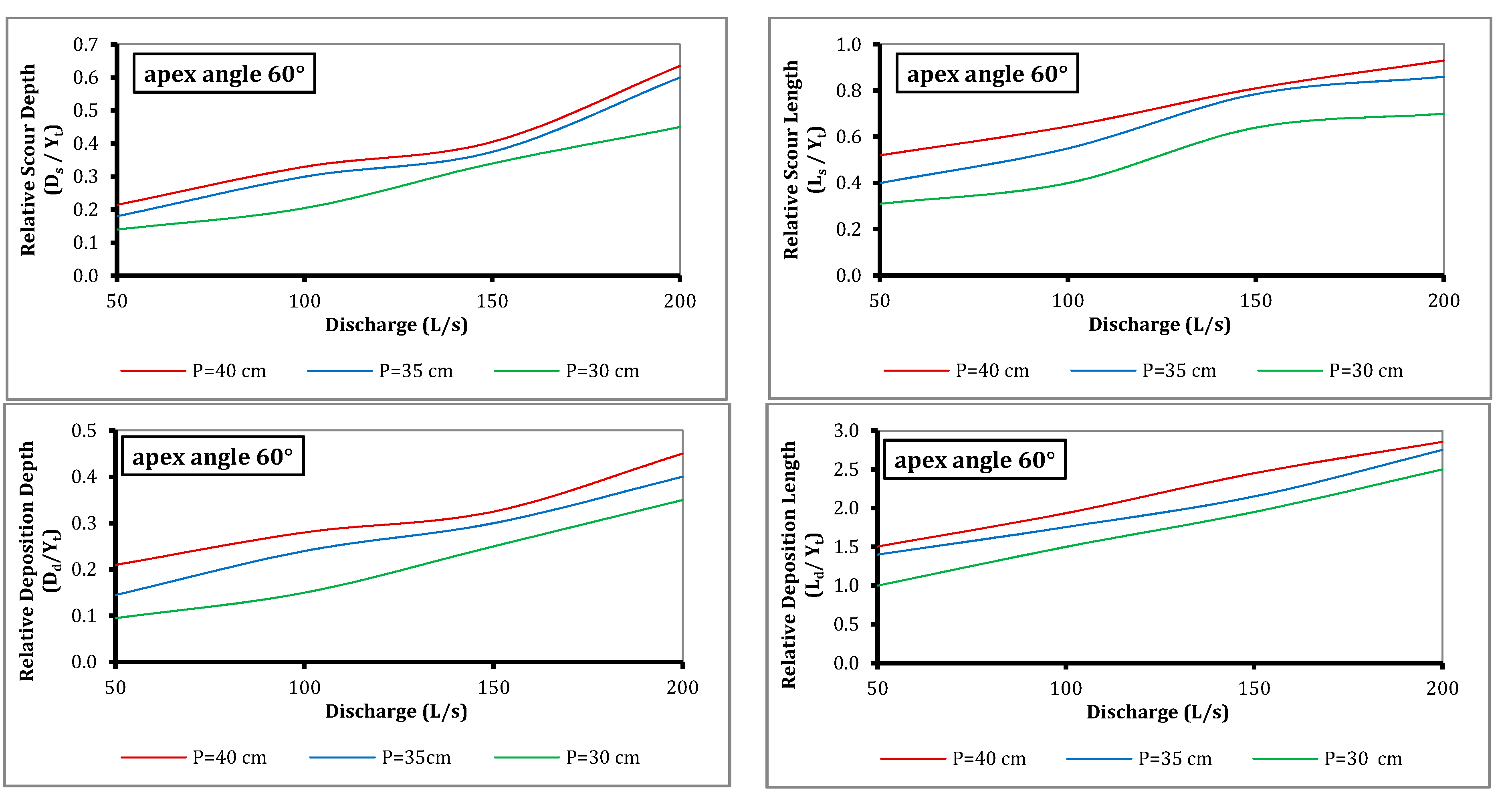
3.2. Effect of Labyrinth Weir Height on Scour and Deposition Parameters

From the previous analysis, it was found that the trapezoidal labyrinth weir with an apex angle of 60° had the lowest scour/deposition values for both scour depth and deposition length. Therefore, this apex angle of 60° was chosen for investigating the effects of changing the weir heights with different applied discharges. This study examined the impact of reducing weir height from 40 cm to 35 cm and 30 cm on relative scour and deposition parameters (Ls/yt, Ds/yt, Ld/yt, Dd/yt) across the tested ranges of discharges. Figure 8 shows the relationships between the conveyed discharge and scour/deposition parameters for different weir heights (40 cm, 35 cm, and 30 cm) at a constant apex angle of 60°. The scour/deposition parameters downstream of the 60° apex angle generally increase with increasing discharge for the tested weir heights. However, for a given discharge, reducing the weir height from 40 cm to 35 cm and then to 30 cm results in a decrease in all scour and deposition parameters, with the magnitude of improvement varying inversely with discharge.
The most considerable improvements were observed at the lowest discharge (50 L/s), where reducing the weir height to 30 cm resulted in reductions of 40%, 35%, 34%, and 55% for Ls/yt, Ds/yt, Ld/yt, and Dd/yt, respectively. As discharge increased, the efficacy of height reduction declined, though the improvements remained significant. At 200 L/s, the 30 cm weir height still yielded reductions of 25%, 29%, 12%, and 22% for the same parameters. The 35 cm weir height showed a similar trend but with more modest improvements, ranging from 23 to 31% at 50 L/s and from 4 to 11% at 200 L/s. Notably, deposition depth (Dd/yt) exhibited the most substantial response to height reduction, particularly at lower discharges. Conversely, deposition length (Ld/yt) showed the least improvement at higher discharges. To clearly present the comparative performance of different weir configurations, Table 2 summarizes the percentage reductions in scour and deposition parameters for the 60° angle weir, compared to other configurations across different weir heights. This tabular format allows for a comprehensive view of the results across various parameters and experimental conditions.
From these results, it is obvious that for a given discharge, reducing the weir height from 40 cm to 35 cm and to 30 cm results in a decrease in the scour/deposition parameters downstream of the trapezoidal labyrinth weir. This trend is observed for all apex angles (20°, 45°, 60°, and 80°), as well as for the linear crest. The reduction in these parameters can be attributed to the lower upstream water levels, decreased flow velocities, reduced turbulence, and lower sediment transport capacities, associated with lower weir heights.
These findings suggest that reducing the weir height can be an effective strategy for mitigating scour and deposition downstream of labyrinth weirs, particularly under low to moderate flow conditions. However, the deteriorating returns at higher discharges indicate that other factors may become more influential in determining scour and deposition characteristics as flow rates increase. This highlights the importance of considering a range of flow conditions when optimizing labyrinth weir designs for scour and deposition control. It is important to note that reducing the weir height can effectively mitigate downstream scour and deposition. Other considerations such as discharge capacity, energy dissipation requirements, and structural stability may also play a role in determining the optimal weir height for a specific application.

4. Conclusions

This study investigates the performance of trapezoidal labyrinth weirs in controlling flow and mitigating scour in straight channels. The research examines various weir configurations, focusing on different apex angles (20°, 45°, 60°, and 80°) and weir heights (40 cm, 35 cm, and 30 cm). The experiments were conducted using a physical model, applying different discharges (50, 100, 150, and 200 L/s) to each configuration, concluding a total of 60 different runs in the physical model. This study measures and analyzes key parameters, including the developed local bed configurations in terms of geometry of scour and deposition. Comparisons were made between the labyrinth weirs and traditional linear sharp-crested weirs to assess relative performance. The research aimed to identify optimal design characteristics for minimizing downstream erosion and sediment transport while considering factors such as weir height and flow conditions. Across all tested conditions, the 60° apex angle labyrinth weir showed the optimum performance in reducing the scour and deposition geometries downstream of the control structure. Compared to the classical sharp-crested linear weir, the 60° labyrinth weir reduced scour depth by up to 41% and scour length by up to 50%, deposition depth by up to 40%, and deposition length by up to 50%. These enhancements imply that the 60° angle represents the best compromise between expanding the effective crest length and preserving a flow pattern that reduces erosion downstream.
The research also reveals that weir height has a substantial impact on scour and deposition parameters. Generally, lower weir heights result in decreased scour and deposition. This effect is particularly obvious at lower discharges, though the improvements tend to reduce as the flow rates increase. It is worth noting that scour depth and length are found to be more sensitive to height changes than deposition length, especially under higher flow conditions. Across all configurations, this study finds that scour and deposition parameters generally increase with higher discharges. This highlights the importance of considering a range of flow conditions when designing labyrinth weirs for effective scour and deposition control. The findings contribute to understanding the interplay between weir geometry, flow conditions, and sediment transport dynamics, providing insights for optimizing labyrinth weir designs to minimize downstream scour and deposition, while considering other design criteria, such as discharge capacity and structural stability. Selecting the appropriate apex angle and weir height requires balancing energy dissipation with minimizing scour and deposition based on project-specific requirements.
Generally, this research has significant practical implications for creating more efficient, sustainable, and durable water management structures by showing how optimized labyrinth weir designs can balance hydraulic efficiency with erosion control. This study connects engineering solutions with environmental needs. These findings are especially important for sustainable water management and adapting to regular changing flow conditions.

Author Contributions

Conceptualization, I.M.M. and A.S.; data curation, A.H.S., H.A.H., I.M.M. and A.S.; formal analysis, I.M.M. and A.S.; investigation, H.A.H., I.M.M. and A.S.; methodology, A.H.S., T.F.Y., I.M.M. and A.S.; writing—original draft, A.S.; writing—review and editing, A.H.S., T.F.Y., I.M.M. and A.S. All authors have read and agreed to the published version of the manuscript.

Funding

This research received no external funding.

Data Availability Statement

Data is contained within the article.

Conflicts of Interest

The authors declare no conflicts of interest.

References

  1. Döll, P. Impact of Climate Change and Variability on Irrigation Requirements: A Global Perspective. Clim. Chang. 2002, 54, 269–293. [Google Scholar] [CrossRef]
  2. Oki, T.; Kanae, S. Global Hydrological Cycles and World Water Resources. Science 2006, 313, 1068–1072. [Google Scholar] [CrossRef] [PubMed]
  3. Ghaderi, A.; Daneshfaraz, R.; Dasineh, M.; Di Francesco, S. Energy Dissipation and Hydraulics of Flow over Trapezoidal–Triangular Labyrinth Weirs. Water 2020, 12, 1992. [Google Scholar] [CrossRef]
  4. Falvey, H.T. Hydraulic Design of Labyrinth Weirs; ASCE Press (American Society of Civil Engineers): Reston, VA, USA, 2003; ISBN 0784406316. [Google Scholar]
  5. Sah, S.; Kumar, M.; Singh, D.; Sah, S.; Kumar, M.; Singh, D. Study of Flow Characteristic of Trapezoidal Labyrinth Weir. River Hydraul. Hydraul. Water Resour. Coast. Eng. 2022, 2, 241–248. [Google Scholar] [CrossRef]
  6. Emin Emiroglu, M.; Cihan Aydin, M.; Kaya, N. Discharge Characteristics of a Trapezoidal Labyrinth Side Weir with One and Two Cycles in Subcritical Flow. J. Irrig. Drain. Eng. 2014, 140, 04014007. [Google Scholar] [CrossRef]
  7. Idrees, A.K.; Al-Ameri, R. Investigating a New Approach to Enhance the Discharge Capacity of Labyrinth Weirs. J. Hydroinform. 2023, 25, 300–317. [Google Scholar] [CrossRef]
  8. Hong, S.; Biering, C.; Sturm, T.; Yoon, K.; Gonzalez-Castro, J. Effect of Submergence and Apron Length on Spillway Scour: Case Study. Water 2015, 7, 5378–5395. [Google Scholar] [CrossRef]
  9. Derakhshanifard, M.; Heidarnejad, M.; Masjedi, A.; Bordbar, A.; Egdernezhad, A. Experimental Study of Effect of Creating an Additional Cycle along the Lateral Crest of the Labyrinth Weirs. Flow Meas. Instrum. 2023, 90, 102306. [Google Scholar] [CrossRef]
  10. Azmathullah, H.M.D.; Deo, M.C.; Deolalikar, P.B. Estimation of Scour below Spillways Using Neural Networks. J. Hydraul. Res. 2006, 44, 61–69. [Google Scholar] [CrossRef]
  11. Goel, A.; Pal, M. Application of Support Vector Machines in Scour Prediction on Grade-Control Structures. Eng. Appl. Artif. Intell. 2009, 22, 216–223. [Google Scholar] [CrossRef]
  12. Eslinger, K.R.; Crookston, B.M. Energy Dissipation of Type a Piano Key Weirs. Water 2020, 12, 1253. [Google Scholar] [CrossRef]
  13. Sharafati, A.; Haghbin, M.; Haji Seyed Asadollah, S.B.; Tiwari, N.K.; Al-Ansari, N.; Yaseen, Z.M. Scouring Depth Assessment Downstream of Weirs Using Hybrid Intelligence Models. Appl. Sci. 2020, 10, 3714. [Google Scholar] [CrossRef]
  14. Rajaei, A.; Esmaeili Varaki, M.; Shafei Sabet, B. Experimental Investigation on Local Scour at the Downstream of Grade Control Structures with Labyrinth Planform. ISH J. Hydraul. Eng. 2020, 26, 457–467. [Google Scholar] [CrossRef]
  15. Tullis, B.P.; Jorgensen, T.J.; Crookston, B.M. Effects of a Labyrinth Weir with Outlet Ramps on Downstream Steep-Stepped Chute Sidewall Height Requirements. J. Irrig. Drain. Eng. 2021, 147, 04021057. [Google Scholar] [CrossRef]
  16. Idrees, A.K.; Al-Ameri, R. A Review of Hydraulic Performance and Design Methods of Labyrinth Weirs. Water Supply 2022, 22, 8120–8138. [Google Scholar] [CrossRef]
  17. Kardan, N.; Hassanzadeh, Y.; Shakooei Bonab, B. Shape Optimization of Trapezoidal Labyrinth Weirs Using Genetic Algorithm. Arab. J. Sci. Eng. 2017, 42, 1219–1229. [Google Scholar] [CrossRef]
  18. Masoudi, M.H.; Yari, A.; Sadeghian, J.; Norouzi, H. Experimental Investigation of the Discharge Coefficient of the Rectangular and Trapezoidal Labyrinth Weirs Considering Variable Congress Lengths. Model. Earth Syst. Environ. 2024, 10, 2819–2832. [Google Scholar] [CrossRef]
  19. Elnikhely, E.A.; Fathy, I. Prediction of Scour Downstream of Triangular Labyrinth Weirs. Alex. Eng. J. 2020, 59, 1037–1047. [Google Scholar] [CrossRef]
  20. Yasi, M.; Azizpour, B. Comparative Experimental Study on Local-Scour Downstream of Labyrinth Weirs with Different Planforms. Iran. J. Sci. Technol. Trans. Civ. Eng. 2023, 48, 2663–2677. [Google Scholar] [CrossRef]
  21. Ikinciogullari, E.; Emiroglu, M.E.; Aydin, M.C. Comparison of Scour Properties of Classical and Trapezoidal Labyrinth Weirs. Arab. J. Sci. Eng. 2022, 47, 4023–4040. [Google Scholar] [CrossRef]
  22. Dehghani, H.S.; Varaki, M.E. Experimental Investigation of Upstream Sedimentation and Downstream Bed Levels’ Effects on Discharge Coefficients of Trapezoidal Labyrinth Weirs. Arab. J. Geosci. 2021, 14, 1999. [Google Scholar] [CrossRef]
  23. Obaida, A.A.M.; Khattab, N.I.; Mohammed, A.Y. Scour Depth Downstream Sharp-Crested Weir. J. Eng. Appl. Sci. 2023, 70, 23. [Google Scholar] [CrossRef]
  24. Guan, D.; Melville, B.; Friedrich, H. Local Scour at Submerged Weirs in Sand-Bed Channels. J. Hydraul. Res. 2016, 54, 172–184. [Google Scholar] [CrossRef]
  25. Fathi, A.; Abdi Chooplou, C.; Ghodsian, M. Local Scour Downstream of Type-A Trapezoidal Stepped Piano Key Weir in Sand and Gravel Sediments. ISH J. Hydraul. Eng. 2024, 30, 417–429. [Google Scholar] [CrossRef]
  26. Guan, D.; Liu, J.; Chiew, Y.-M.; Zhou, Y. Scour Evolution Downstream of Submerged Weirs in Clear Water Scour Conditions. Water 2019, 11, 1746. [Google Scholar] [CrossRef]
  27. Abdi Chooplou, C.; Bodaghi, E.; Ghodsian, M.; Vaghefi, M. Temporal Evolution of Scouring Downstream of a Trapezoidal Piano Key Weir. Int. J. River Basin Manag. 2024, 22, 351–364. [Google Scholar] [CrossRef]
  28. Pagliara, S.; Kurdistani, S.M. Scour Downstream of Cross-Vane Structures. J. Hydro-Environ. Res. 2013, 7, 236–242. [Google Scholar] [CrossRef]
  29. Najafzadeh, M.; Saberi-Movahed, F.; Sarkamaryan, S. NF-GMDH-Based Self-Organized Systems to Predict Bridge Pier Scour Depth under Debris Flow Effects. Mar. Georesour. Geotechnol. 2018, 36, 589–602. [Google Scholar] [CrossRef]
  30. Karbasi, M.; Md Azamathulla, H. Prediction of Scour Caused by 2D Horizontal Jets Using Soft Computing Techniques. Ain Shams Eng. J. 2017, 8, 559–570. [Google Scholar] [CrossRef]
Figure 1. General layout of the physical model (20.5 m long, 2 m width, and 0.85 m depth), (a) an upper view of the physical model, (b) a side view of the model showing its longitude, (c) a view of the upstream entrance, and (d) a view of the downstream outlet.
Water 16 02443 g001
Figure 2. Schematic diagram for the weir model, and experimental setup: (a) side view, (b) plan.
Water 16 02443 g002
Figure 3. The schematic diagram for the trapezoidal labyrinth weir with four different apex angles (20°, 45°, 60°, and 80°)—“the red line shows the borders of one cycle of the weir from the schematic diagram to the natural view in the flume”.
Water 16 02443 g003
Figure 4. Grain size distribution of the bed material downstream of the solid apron.
Water 16 02443 g004
Figure 5. The calibrated point gauges to measure (a) the upstream water level, (b) the developed bed configurations, and (c) the tailgate water level.
Water 16 02443 g005
Figure 6. Scour developed downstream of the apron: (a) before the test run, (b) after the test run, and (c) a side view of the resulting scour and deposition.
Water 16 02443 g006
Figure 7. The relation between flow discharge and relative scour/deposition parameters (Ds/Yt), (Ls/Yt), (Dd/Yt), and (Ld/Yt) for the linear case and the other apex angles at different weir heights: (a) P = 40 cm, (b) P = 35 cm, and (c) P = 30 cm.
Water 16 02443 g007aWater 16 02443 g007b
Figure 8. Relationship between passing discharge and scour/deposition parameters (Ds/yt), (Ls/yt), (Dd/yt), and (Ld/yt), for a weir apex angle of 60° and different weir heights (P = 40 cm, 35 cm, and 30 cm).
Water 16 02443 g008
Table 1. The important parameters affecting scour and deposition.
Pweir heightgthe gravity acceleration
Dsmaximum scour depth ρ water density
Ls ρ ρ soil particle density
Ddmaximum deposition depthSois the flume bed slope
Ldmaximum deposition lengthd50median grain size
Qpassing discharge (L/s)Vthe mean flow velocity
Wwidth of the channelμdynamic water viscosity
Lblength of the concrete apronσthe surface tension
yttailwater depthNtotal number of weir cycles
αthe labyrinth weir apex angle
Table 2. Comparative performance of the 60° apex angle labyrinth weir in reducing scour and deposition. The numbers are represented as %.
P = 40 cmP = 35 cmP = 30 cm
α = 80°α = 45°α = 20°Linearα = 80°α = 45°α = 20°Linearα = 80°α = 45°α = 20°Linear
Scour depth (Ds/yt)331023413310233546183529
Scour length (Ls/yt)361527503814264039163325
Deposition depth (Dd/yt)391430404214304050253529
Deposition length (Ld/yt)351728503716294040173125
Disclaimer/Publisher’s Note: The statements, opinions and data contained in all publications are solely those of the individual author(s) and contributor(s) and not of MDPI and/or the editor(s). MDPI and/or the editor(s) disclaim responsibility for any injury to people or property resulting from any ideas, methods, instructions or products referred to in the content.

