Article

Numerical Study on the Hydraulic and Mixing Performance of Fluid Flow within a Channel with Different Numbers of Sector Bodies

School of Mechanical Engineering, University of Shanghai for Science and Technology, Shanghai 200093, China
*
Author to whom correspondence should be addressed.
Water 2024, 16(17), 2451; https://doi.org/10.3390/w16172451
Submission received: 24 July 2024 / Revised: 16 August 2024 / Accepted: 27 August 2024 / Published: 29 August 2024
(This article belongs to the Section Hydraulics and Hydrodynamics)

Abstract

:
This study numerically analyzes and compares the outlet mixing efficiency (Mout), the pressure loss (ΔP), and the comprehensive performance parameter η, defined as the ratio between Mout and dimensionless pressure drop, of fluid flow in mixing channels with a single sector body (CSSB), dual sector bodies (CDSB), and triple sector bodies (CTSB). This analysis is conducted under a Reynolds number based on the dimension of the sector body Red = 100. The analysis reveals that both for the CDSB and CTSB, when the spacing distance between the sector bodies is small, the downstream sector body blocks the vortex shedding, resulting in a low mixing degree. Increasing the spacing distance between the sector bodies can significantly improve the mixing performance. When comparing the performance of three configurations, it is found that only when the spacing distances between the sector bodies in CDSB and CTSB are large enough, their outlet mixing efficiencies converge to a closed value, surpassing that of CSSB, but at the expense of a substantial pressure loss. Moreover, the CSSB consistently outperforms the CDSB and CTSB in terms of comprehensive performance. This study provides insights into the selection and spacing of bluff bodies in channels to achieve desirable hydraulic and mixing performance.

1. Introduction

Microfluidic technology has emerged as a powerful tool in various fields, including biomedical diagnostics and chemical synthesis [1,2,3,4]. A key component of microfluidic systems is the micro-mixer, which plays a crucial role in achieving efficient and rapid mixing of fluids within confined channels. Based on the working principles and structural characteristics, microfluidic mixers can be classified into two categories: active and passive mixers. Active micro-mixers utilize external forces or energy inputs, such as ultrasonic waves or electromagnetic fields, to achieve excellent forced mixing of fluids. However, they suffer from drawbacks such as high energy consumption and complex device configurations. In contrast, passive micro-mixers offer several advantages, such as their compact structure, low energy consumption, and ease of integration into microfluidic platforms [5]. Considerable efforts have been made towards optimizing the design of passive micro-mixers.
Various structural designs have been explored to improve the hydraulic and mixing performance of micro-mixers, such as splitting and recombining (SAR) structures [6,7], serpentine [8,9,10] or wavy structures [11,12], Tesla structures [13,14] and micro-mixers with baffles and obstacles [15,16,17]. For instance, Chen et al. [6] designed SAR micro-mixers with F-shaped mixing units, and their numerical and experimental results showed that the mixing efficiency of the SAR micro-mixer reached about 90% when the Reynolds number is increased from 15 to 50. Wang et al. [10] proposed a novel serpentine micro-mixer utilizing an elliptical curve design, and their numerical simulations revealed that the elliptical curve micro-mixer introduced Dean vortices, which led to improved mixing performance and lower pressure loss. Hossain et al. [14] examined the impact of various obstruction shapes (circular, diamond, and rectangular) on the mixing efficiency of a micro-mixer with Tesla structures. Their investigation revealed that the micro-mixer with circular obstructions within the Tesla structures demonstrated favorable results in terms of both mixing performance and energy conservation. Zhang et al. [17] studied the impact of a cylindrical pin at various positions on mixing performance of a micro-mixer. They found that a slightly offset position from the centerline provided the optimal mixing performance. However, when vortex shedding is present, a pin located on the channel centerline exhibited the best mixing performance.
Among these designs, the use of bluff bodies within the channels has wide-ranging applications due to their advantages, including simplicity, ease of fabrication, low manufacturing costs, and the ability to transition flow patterns from laminar flow to vortex flow. The simplest design for mixing enhancement with bluff bodies is a channel with a single bluff body [17,18,19,20,21,22,23]. However, this enhancement is primarily localized around the bluff body itself, because the vortex shedding behind the body has a limited effect on the fluid near the channel walls, resulting in non-uniform mixing efficiency throughout the entire channel. To increase the outlet mixing efficiency, it is often necessary to increase the size of the bluff body, which may suppress the generation and shedding of vortices [17].
To address the constraints of a single bluff body design, many investigators have investigated the effects of dual bluff bodies [24,25,26,27,28,29,30] and multiple bluff bodies [31,32,33,34,35,36,37] on mixing. For instance, Zhang et al. [24] experimentally studied the influence of dual cylindrical obstacles in series and staggered arrangements on the flow and mixing performance of a micro-mixer. Their findings indicated that vortex shedding in the series arrangement enhances mixing performance. Xiao and Jing [25] conducted a numerical investigation on the effects of the spacing distance between two bluff bodies with various shapes within a mixing channel on the pressure loss and outlet mixing efficiency. Their findings demonstrated that increasing the spacing distance over a large range can improve the comprehensive performance parameters and outlet mixing efficiency when the Red = 60 and 100. Among the various shapes of bluff bodies investigated, the sector bluff body exhibited the best mixing performance. Bhagat et al. [31] designed a 3D passive microfluidic mixer with multiple diamond-shaped bluff bodies to improve the mixing at low Reynolds numbers. Dundi et al. [32] achieved good mixing performance at the cost of a slight increase in pressure loss by incorporating cylindrical elements into a T-T mixer. Antognoli et al. [33] designed a micro-mixer with a sequence of 20 cylindrical obstacles in a channel and achieved good mixing.
Although researchers have extensively studied the performance of fluid flow within micro channels with different numbers of bluff bodies in terms of its hydraulic and mixing capabilities, there is a lack of comparative analysis regarding the performance differences among these configurations. Furthermore, the comprehensive hydraulic and mixing performance of mixing channels with different numbers of bluff bodies has also not been thoroughly evaluated. It is important to consider both the mixing performance and the pressure losses associated with increasing the number of bluff bodies within the channel, because mixing enhancement often comes at the cost of increased pressure loss. Therefore, this study designs mixing channels with different numbers of bluff bodies to analyze and compare their outlet mixing efficiency, pressure loss between the inlet and outlet of the channel, and comprehensive hydraulic and mixing performance, where the purpose is to enhance the performance in terms of hydraulic and mixing capabilities of the mixing channel to the maximum extent by controlling the number of bluff bodies and adjusting the spacing distance between the bluff bodies.

2. Numerical Setup

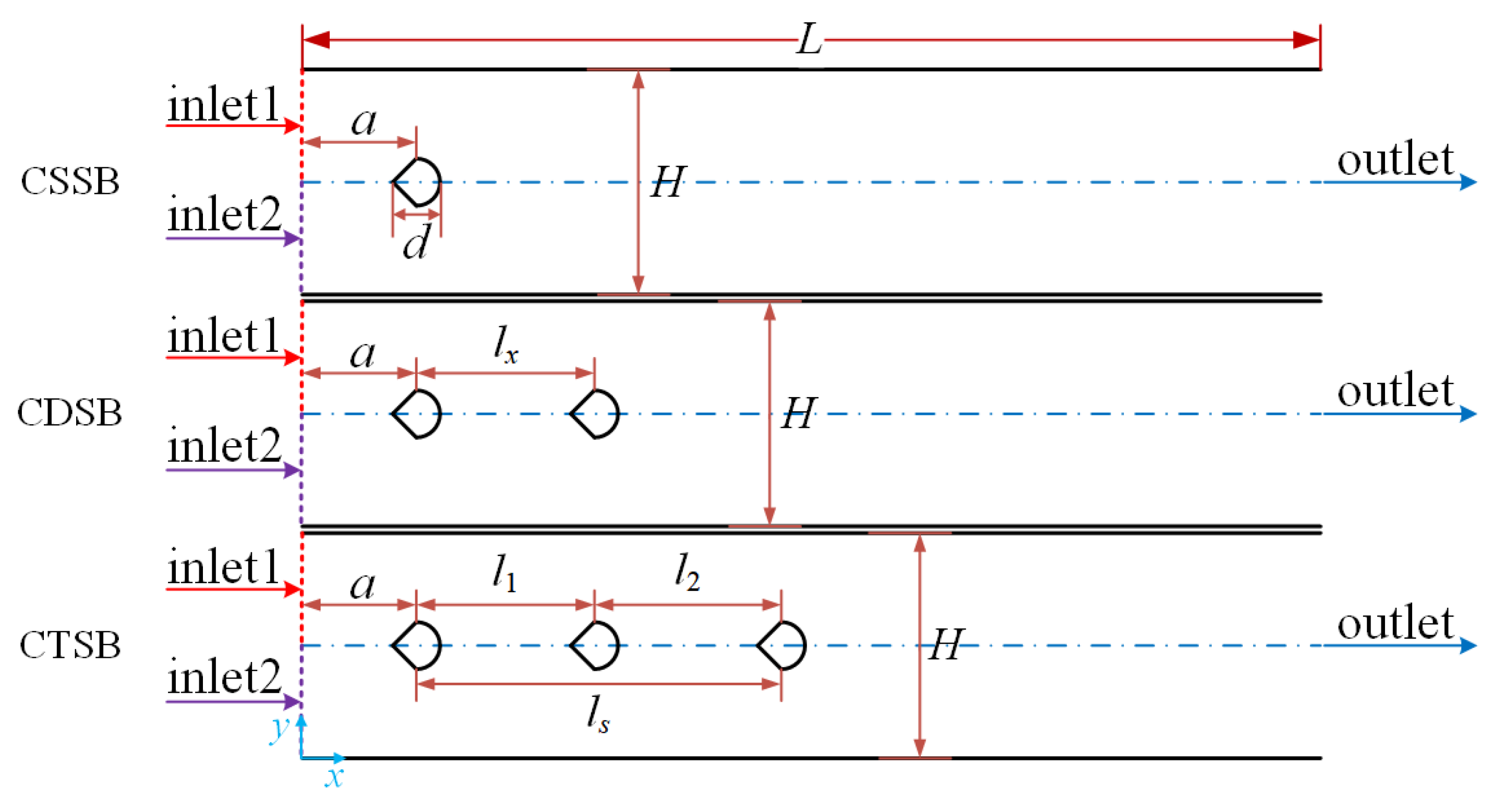
2.1. Simulation Model

To analyze and compare the hydraulic and mixing performance of fluid flow in a mixing channel with different numbers of bluff bodies, three 2D mixing channels with different numbers of sector bluff bodies, which consist of an isosceles right triangle and a semicircle, are employed. These include a channel with a single sector body (CSSB), a channel with dual sector bodies (CDSB), and a channel with triple sector bodies (CTSB), as depicted in Figure 1. Based on the previous research [25], channels with sector bluff bodies exhibit better mixing performance and lower pressure loss when compared to channels with circle and square bluff bodies. The computational domain corresponds to a rectangular region with dimensions of L × H. Within the channel, identical sector bodies with a characteristic dimension of d are arranged in series along the channel center line. The distance between the center of the first sector body and the inlet of the channel is a. For CDSB, the distance between the two sector bodies is denoted as lx. For CTSB, the distances between adjoining sector bodies are, respectively, labeled as l1 and l2, resulting in a total length between the first and the third sector bodies of ls = l1 + l2. The specific geometric parameters of the simulation models are presented in Table 1. In this study, the Reynolds number (Re) based on the dimension of the sector body Red = ρfu0d/μ (where ρf represents the density of fluid, u0 denotes the average inlet velocity, and μ signifies the dynamic viscosity of the fluid) is set to a constant value of Red = 100. Accordingly, the Reynolds number based on the channel height (ReH = ρfu02H/μ) is 800 to insure laminar flow states at the channel inlet.

2.2. Numerical Methods

For the purpose of simplification, the flow within the mixing channel is considered to be characterized by incompressible Newtonian laminar flow. The fluid flow within the channel is governed by the following equations.
Continuity equation:
u = 0
Momentum equation:
ρ f u t + ρ f u u + P μ 2 u = 0
where u, t, and P are the velocity of fluid, time, and the pressure of the fluid, respectively.
The mixing between the fluids within the mixing channel can be solved using a convection–diffusion equation, which is expressed as follows:
c t + u c = D c 2 c
where c represents the liquid concentration, and Dc = 1 × 10⁻⁹ m2/s denotes the coefficient of diffusion.
In order to conduct the simulation, a fully developed parabolic velocity profile is prescribed at the inlet of the channel, and it can be expressed as follows [38]:
u i n = 3 2 u 0 ( 4 y H 2 ) ( H y )
where uin represents the inlet flow velocity.
In this work, two liquids with identical density, expressed as ρf = 1 × 10³ kg/m3, and viscosity, expressed as μ = 0.001 Pa·s, but different ionic concentrations of 1 mol/m3 and 0 mol/m3, are introduced through inlet1 and inlet2, respectively, for the numerical investigation of the mixing process. The average inlet velocity is set to be 0.1 m/s to achieve the Reynolds number of Red = 100. At the channel outlet, the pressure is set to zero. A no-slip boundary condition is imposed on all channel walls and sector body surfaces.
The governing equations are solved using the COMSOL Multiphysics 5.4 to obtain velocity fields, concentration profiles, and pressure distributions within the mixing channel with different numbers of sector bodies.
In order to evaluate the performance of fluid flow in a mixing channel with different numbers of bluff bodies in terms of its hydraulic and mixing capabilities, the pressure loss ΔP of the mixing channel from the inlet to the outlet is utilized for quantification. At Red = 100, periodic vortex shedding takes place behind the sector bodies, causing variations in the pressure field over time and position. Consequently, the pressure loss is determined utilizing a method that involves averaging over both time and position. The calculation formula is as follows [39]:
Δ P = T H P i n y , t P o u t ( y , t ) d y d t T H
where Pin and Pout indicate the inlet and outlet pressures of the mixing channel, respectively, and T corresponds to a period of time after achieving periodic stability of the mixing occurring inside the channel.
In the same way, the mixing performance at the channel outlet is evaluated using the outlet mixing efficiency Mout. The time- and position-averaged value of Mout is computed by [39]
M o u t = T H | c i y , t c r e f ( y , t ) | d y d t T H c r e f
where ci represents the concentration profile of the liquid at the mixing channel outlet, while cref denotes the reference concentration, which is defined as 0.5 mol/m3 in accordance with the model established in this study.
In order to further investigate the comprehensive hydraulic and mixing performance of fluid flow in a mixing channel with different numbers of bluff bodies, a comprehensive performance parameter, denoted as η, is introduced. Its representation is as follows [40]:
η = M o u t P * = M o u t P / ρ f u 0 2
where ΔP* is the dimensionless pressure loss.

2.3. Mesh Convergence Test and Data Validation

To guarantee precision of numerical results and computational efficiency, a mesh convergence test was conducted as a preliminary step, using a CTSB simulation model with parameters set as l1 = 6d, l2 = 2d and Red = 100. Five sets of simulations were performed using tetrahedral grids with different numbers of elements. Table 2 summarizes the outlet mixing efficiency, its relative error, and the computational time for each mesh configuration. After evaluating both accuracy and efficiency, the mesh configuration with 43,832 elements was selected for subsequent simulations.
In addition to performing a mesh convergence test, two sets of data validation have been conducted to assess the accuracy of the present numerical method by comparing the results with those reported in the literature. The first data validation involves the comparison of the influence of blockage ratio on the drag coefficient of a square cylinder inside a channel at a different Re. The second data validation compared the influence of a rectangular cylinder with different aspect ratio on the mixing efficiency of fluid flow in a channel. Detailed information regarding the data validations can be found in our previous research [25], which demonstrates consistency between the outcomes obtained using our numerical method and the outcomes obtained in the literature.

3. Results and Discussion

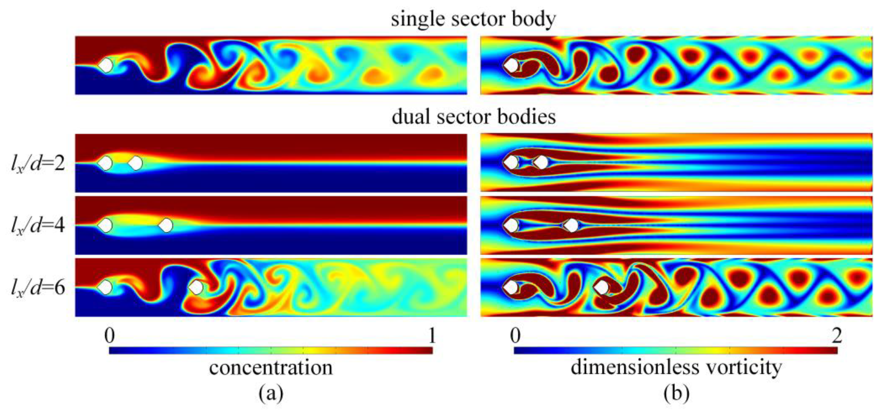
3.1. Performance of CDSB

To analyze the hydraulic and mixing performance of fluid flow within a CDSB, Figure 2a illustrates the outlet mixing efficiency and pressure loss of the fluid flow within the CDSB, with various spacing distances measured. The outlet mixing efficiency and pressure loss of fluid flow within a CSSB are also given for reference. The results demonstrate that the outlet mixing efficiency and the pressure loss of the CDSB remain relatively stable and low at first and then remarkably enhance to higher values as the spacing distance between the two sector bodies increases. This trend indicates that there exists a critical value of spacing distance for the dual sector bodies. When the spacing distance is smaller than the critical value, the outlet mixing efficiency and pressure loss of the CSSB surpass those of the CDSB. Nevertheless, when the spacing distance surpasses the critical value, the CDSB exhibits higher outlet mixing efficiency and pressure loss. Figure 2b compares the comprehensive performance of the CSSB and the CDSB. The findings demonstrate that the comprehensive performance of the CDSB exhibits a trend comparable to that of the outlet mixing efficiency and pressure loss, and that it is always lower than that of the CSSB.
To elucidate the reasons behind these phenomena, Figure 3 presents the example concentration and dimensionless vorticity contours (ω* = ωd/u0, where ω denotes vorticity) within CSSB and CDSB at various spacing distances. Within the CSSB, periodic shedding of vortices occurs behind the sector when Red = 100. These vortices enhanced fluid mixing by disturbing the fluids, leading to a relatively high degree of mixing. For the CDSB, when the spacing distance between the dual sector bodies is small, the shear layer originating from the first sector body undergoes reattachment to the second sector body. This reattachment causes the second sector body to act as a “flow stabilizer”, inhibiting vortex shedding behind the sector bodies [24], and resulting in a lower outlet mixing efficiency than that of the CSSB. In contrast, once the spacing distance between the dual sector bodies surpasses a certain value, a sufficient gap is created, facilitating the formation of periodic shedding vortices behind the first sector body. As a result, the inhibiting effect of the second sector body on vortex shedding diminishes. As the shedding vortices interact with the front profile of the second sector body, they intensify the disruption of the fluid interface and greatly enhance the outlet mixing efficiency. The inclusion of the second sector body introduces secondary disturbances, resulting in higher mixing efficiency for the CDSB in comparison to the CSSB at larger spacing distances.
Furthermore, at a small spacing distance, the fluid flow within the CDSB maintains a laminar state, resulting in lower pressure loss when compared to the vortex flow within the CSSB. With the increment of the spacing distance between the dual sector bodies, the length of these narrow passages confined by the channel walls and the sector bodies becomes longer, leading to a gradual rise in pressure loss. As the spacing distance between the dual sector bodies reaches a sufficient value, the pressure loss experiences a substantial increase due to the formation of vortices within the channel.

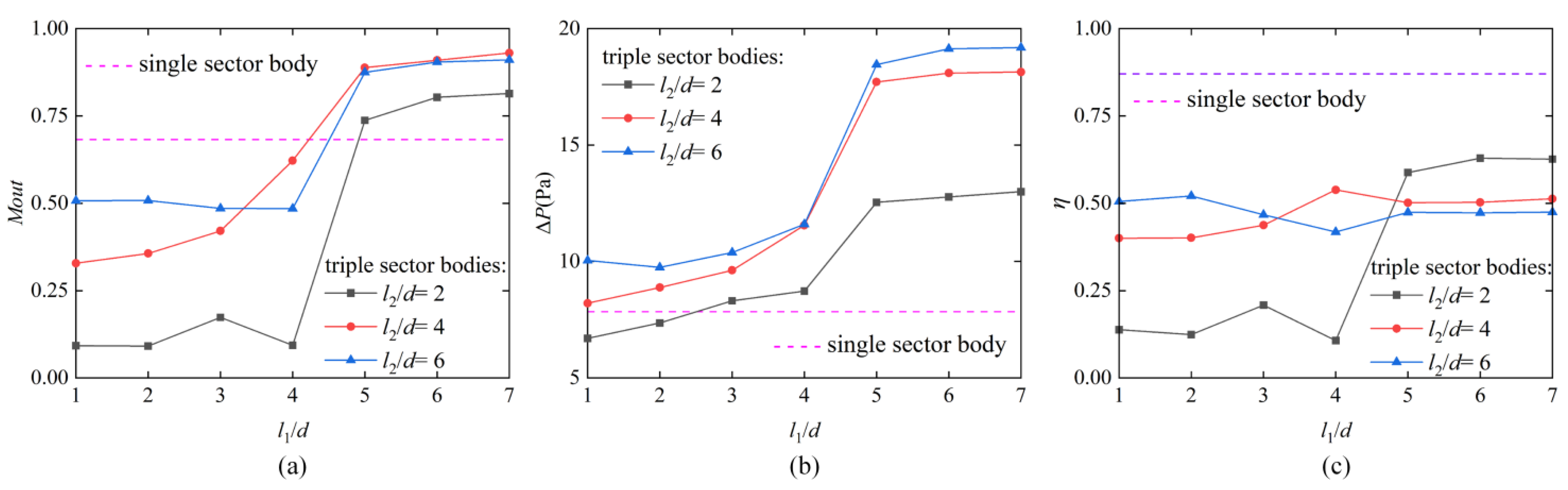
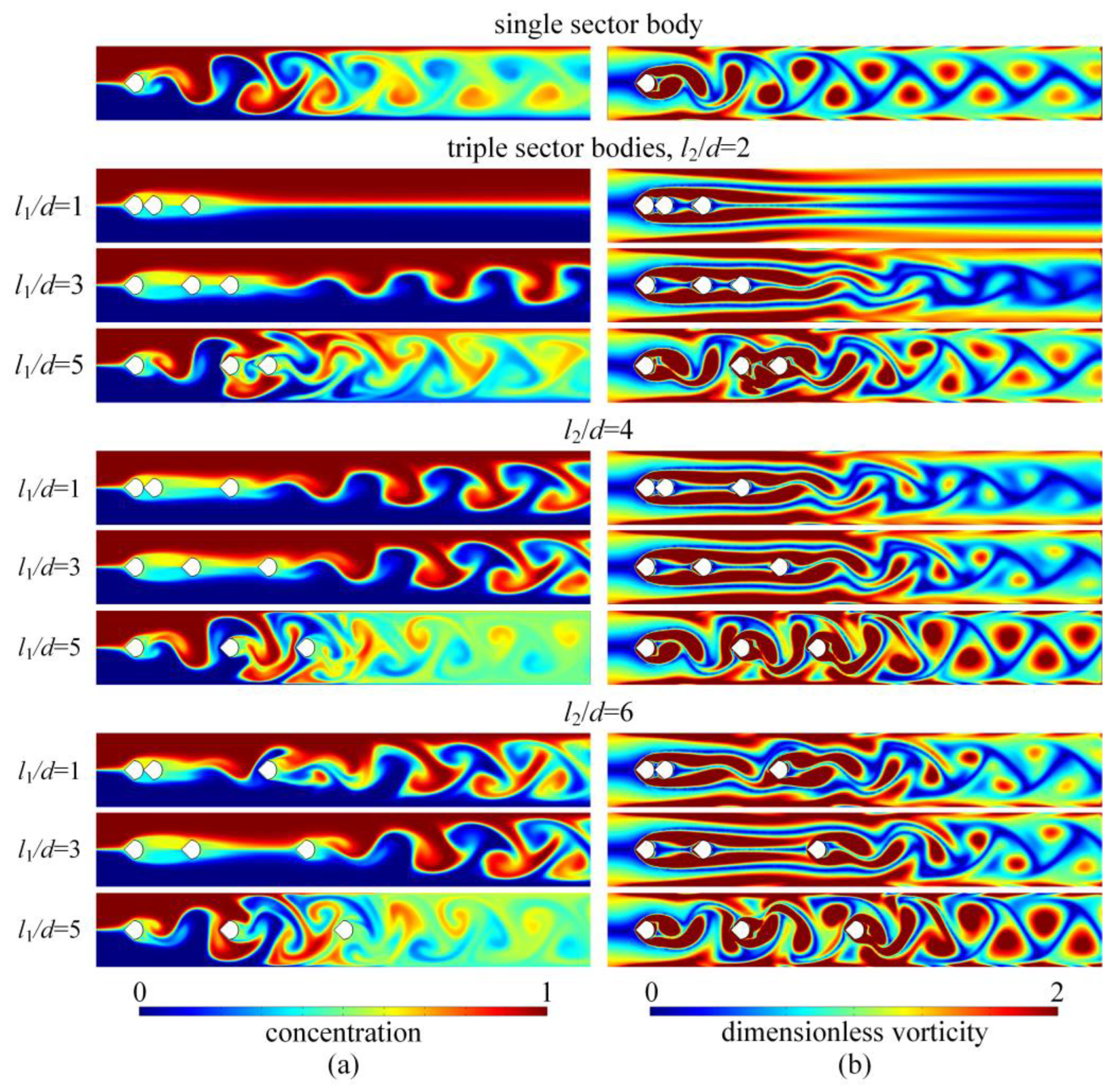
3.2. Performance of CTSB

To analyze the hydraulic and mixing performance of fluid flow within the CTSB, Figure 4a,b illustrate the outlet mixing efficiency and pressure loss of the fluid flow within the CTSB at various spacing distances. The outlet mixing efficiency and pressure loss of fluid flow within a CSSB are also given for comparison. The results shown in Figure 4a indicate that the outlet mixing efficiency of the CTSB initially exhibits relatively low values but increases significantly to high values with the increase in l1 when l2 is fixed, eventually surpassing the outlet mixing efficiency of the CSSB, as depicted. Similarly, the pressure loss of the CTSB follows a trend similar to that of the outlet mixing efficiency, as depicted in Figure 4b. It increases with the increasing l1. With the exception of the cases with small spacing distances l1 and l2 (when l1/d < 3, l2/d = 2), the pressure loss of CTSB is larger than that of the CSSB. Furthermore, Figure 4c compares the comprehensive performance of the CSSB and CTSB. The results indicate that when l2/d = 2, the trend of comprehensive performance follows that of the outlet mixing efficiency. For l2/d = 4 and 6, the comprehensive performance remains relatively stable as l1 increases. The comprehensive performance of CTSB is smaller than the comprehensive performance of the CSSD.
From the concentration and dimensionless vorticity contours w* in Figure 5, it is evident that the reasons for the aforementioned results in the CTSB are similar to those in the CDSB. In the CTSB, when the spacing distances between two adjoining sector bodies are below the critical value, the generation and shedding of vortices behind the sector bodies are suppressed, resulting in lower outlet mixing efficiency. As the spacing distances between two adjoining sector bodies gradually increase, vortex shedding behind the sector bodies begins to form in the channel, resulting in a pronounced enhancement of the outlet mixing efficiency. In addition, at smaller spacing distances, the fluid flow remains more laminar, resulting in lower pressure loss. As the spacing distances increase and vortex shedding occurs, the pressure loss rises due to the increased flow disturbances caused by the vortex shedding.

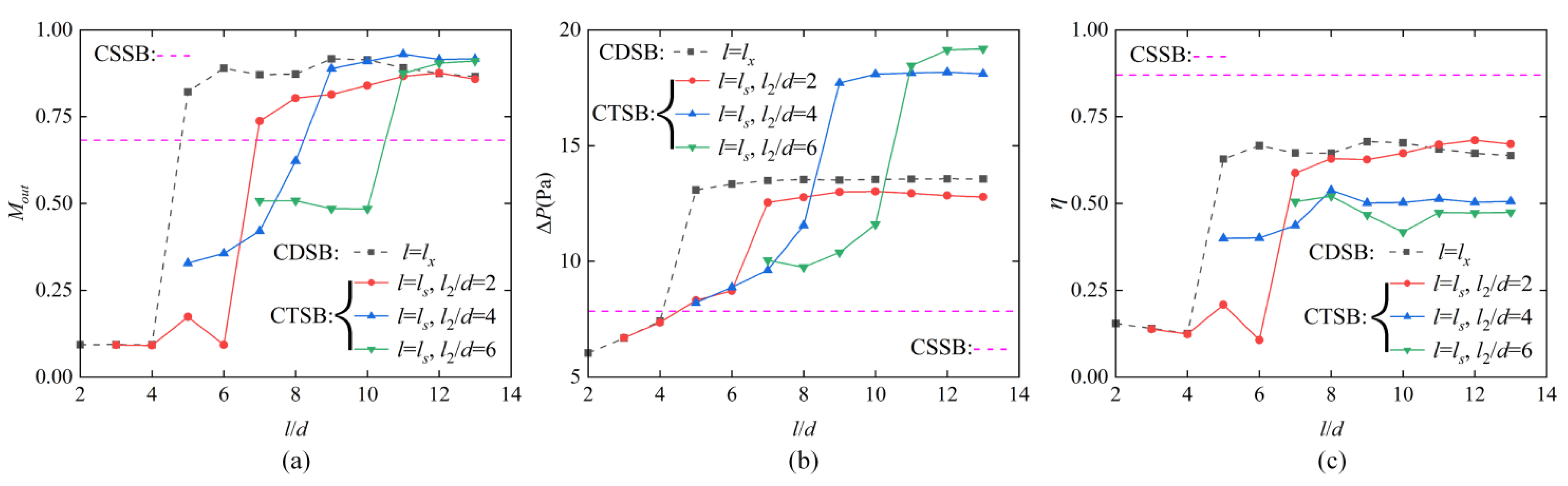
3.3. Performance Comparisons of CSSB, CDSB and CTSB

The hydraulic and mixing performance of fluid flow within CSSB, CDSB and CTSB have been compared, as the results of outlet mixing efficiency, pressure loss, and comprehensive performance of the fluid flow shown in Figure 6. To conduct the comparison, the spacing distance lx of the CDSB was set equal to the total spacing distance ls of the CTSB. The results in Figure 6a,b indicate that within CDSB and CTSB, the outlet mixing efficiency and pressure loss exhibit a similar trend, where both increase from a lower value to a higher value and then stabilize as the spacing distance l increases. This is because as the spacing distance between two adjoining sector bodies increases, the inhibitory effect of the downstream sector body on vortex shedding caused by the upstream sector body weakens, shown through the mixing and vorticity contours illustrated in Figure 7. Regarding the differences in outlet mixing efficiency of CDSB and CTSB, when the spacing distance between the bluff bodies is sufficiently large, the outlet mixing efficiencies of both configurations converge to a similar value. Introducing a third bluff body does not significantly enhance the mixing under these conditions. However, the pressure loss in CTSB is significantly greater than that in CDSB at a large spacing distance ls when l2/d = 4 and 6. This is because the introduction of the third bluff body in the middle enhances flow recirculation and vortex formation around it, increasing the pressure drop for the design of large l1 and l2.
When comparing with CSSB, it can be found that when the spacing distance between the sector bodies in CDSB and CTSB is small, the CDSB and CTSB have smaller outlet mixing efficiency and pressure loss, because the fluid flow within the CDSB and CTSB is transited to the laminar state due to the inhibitory effect of the downstream sector body on vortex shedding. Only when the spacing distances between the sector bodies in CDSB and CTSB are large enough to weaken the inhibitory effect of the downstream sector body are their outlet mixing efficiencies larger than that of CSSB but this will also result in a substantial pressure loss.
Regarding the comprehensive performance in Figure 6c, for both CDSB and CTSB with l2/d = 2, the comprehensive performance exhibits a comparable trend to that of the outlet mixing efficiency, changing from a lower value to a higher and stable value with the increase in spacing distance. However, for l2/d = 4 and 6, the comprehensive performance is relatively stable, but smaller than the optimal value of CDSB and CTSB with l2/d = 2. Furthermore, the CSSB has the best comprehensive performance among the three configurations.

4. Conclusions

This study investigates the performance of fluid flow in terms of its hydraulic and mixing capabilities in channels with three different numbers of sector bodies, including single (CSSB), dual (CDSB), and triple (CTSB) sector bodies. The analysis was conducted at a constant Reynolds number of Red = 100. The key performance parameters include outlet mixing efficiency, pressure loss, and comprehensive performance.
For the CDSB, the outlet mixing efficiency is low when the spacing distance between the two sector bodies is small. With this increment in spacing distance between the two sector bodies, the outlet mixing efficiency initially remains low and then increases significantly. However, this enhancement comes at the expense of a notable pressure loss. A critical spacing value is identified, below which the CSSB exhibits higher outlet mixing efficiency and pressure loss compared to the CDSB. However, beyond the critical value, the CDSB shows higher outlet mixing efficiency and pressure loss. Additionally, the comprehensive performance of the CDSB consistently falls below that of the CSSB. The CTSB exhibits similar trends to the CDSB. However, due to the inhibitory effect of the middle sector body within the CTSB on vortex shedding, except for a few cases, the CTSB consistently exhibits lower comprehensive performance than the CDSB.
When comparing the performance of the three different configurations, it is evident that simply adding the number of sector bodies cannot always enhance the mixing. On the contrary, this might reduce the comprehensive performance by inducing higher pressure loss. It is only when the spacing distance of sector bodies in the CDSB and CTSB is large enough that they exhibit better mixing performance than CSSB. However, the CSSB consistently shows better comprehensive performance compared to both the CDSB and CTSB across all spacing distances. These findings are valuable for the design of micro-mixers for various microfluidic applications, emphasizing the balance needed when increasing the number of bluff bodies to increase outlet mixing efficiency without compromising comprehensive performance due to increased pressure loss.

Author Contributions

J.X.: data curation (equal); formal analysis (equal); investigation (equal); software (equal); validation (equal); visualization (equal); writing—original draft (equal). D.J.: conceptualization (equal); formal analysis (equal); funding acquisition (equal); methodology (equal); project administration (equal); supervision (equal); validation (equal); visualization (equal); writing—review and editing (equal). All authors have read and agreed to the published version of the manuscript.

Funding

This research was funded by the National Natural Science Foundation of China with Grant No. 12272236.

Data Availability Statement

The data that support the findings of this study are available from the corresponding author upon reasonable request.

Acknowledgments

The simulation was supported by the High Performance Computing Center at University of Shanghai for Science and Technology.

Conflicts of Interest

The authors have no conflicts to disclose.

Nomenclature

athe distance between the center of the first sector body and the channel inlet (m)ΔP*dimensionless pressure loss
RedReynolds number based on the sector body dimension
cconcentration of liquid (mol/m3)
ciconcentration (mol/m3)ReHReynolds number based on channel height
crefreference concentration (mol/m3)
Dcdiffusion coefficient (m2/s)Ta period of time after achieving periodic stability of the mixing inside the channel (s)
dcharacteristic dimension of sector body (m)
Hchannel height (m)
Lchannel length (m)ttime (s)
lxthe spacing between the two sector bodies in the channel with dual sector bodies (m)ufluid velocity (m/s)
u0mean inlet velocity (m/s)
l1the spacing between the first two sector bodies in the channel with triple sector bodies (m)uininlet flow velocity (m/s)
ω*dimensionless vorticity
ωvorticity (1/s)
l2the spacing between the last two sector bodies in the channel with triple sector bodies (m)
Acronyms
CSSBchannel with single sector body
lsthe total length between the first and the third sector bodies in the channel with triple sector bodies (m)CDSBchannel with dual sector bodies
CTSBchannel with triple sector bodies
Moutoutlet mixing efficiency (mol2/m6)Greek letters
Ppressure (Pa)μfluid dynamic viscosity (Pa·s)
Pininlet pressure (Pa)ρffluid density (kg/m3)
Poutoutlet pressure (Pa)ηcomprehensive performance parameter
ΔPpressure loss (Pa)

References

  1. Hessel, V.; Löwe, H.; Schönfeld, F. Micromixers—A review on passive and active mixing principles. Chem. Eng. Sci. 2005, 60, 2479–2501. [Google Scholar] [CrossRef]
  2. Lee, C.Y.; Wang, W.T.; Liu, C.C.; Fu, L.M. Passive mixers in microfluidic systems: A review. Chem. Eng. J. 2016, 288, 146–160. [Google Scholar] [CrossRef]
  3. Wang, X.; Liu, Z.; Wang, B.; Cai, Y.; Song, Q. An overview on state-of-art of micromixer designs, characteristics and applications. Anal. Chim. Acta 2023, 1279, 341685. [Google Scholar] [CrossRef] [PubMed]
  4. Bazaz, S.R.; Sayyah, A.; Hazeri, A.H.; Salomon, R.; Mehrizi, A.A.; Warkiani, M.E. Micromixer research trend of active and passive designs. Chem. Eng. Sci. 2024, 293, 120028. [Google Scholar] [CrossRef]
  5. Niculescu, A.G.; Chircov, C.; Bîrcă, A.C.; Grumezescu, A.M. Fabrication and applications of microfluidic devices: A review. Int. J. Mol. Sci. 2021, 22, 2011. [Google Scholar] [CrossRef] [PubMed]
  6. Chen, X.; Shen, J. Simulation and experimental analysis of a SAR micromixer with F-shape mixing units. Anal. Methods 2017, 9, 1885–1890. [Google Scholar] [CrossRef]
  7. Viktorov, V.; Nimafar, M. A novel generation of 3D SAR-based passive micromixer: Efficient mixing and low pressure drop at a low Reynolds number. J. Micromech. Microeng. 2013, 23, 055023. [Google Scholar] [CrossRef]
  8. Javaid, M.U.; Cheema, T.A.; Park, C.W. Analysis of passive mixing in a serpentine microchannel with sinusoidal side walls. Micromachines 2017, 9, 8. [Google Scholar] [CrossRef]
  9. Rhoades, T.; Kothapalli, C.R.; Fodor, P.S. Mixing optimization in grooved serpentine microchannels. Micromachines 2020, 11, 61. [Google Scholar] [CrossRef]
  10. Wang, X.; Liu, Z.; Cai, Y.; Wang, B.; Luo, X. A cost-effective serpentine micromixer utilizing ellipse curve. Anal. Chim. Acta 2021, 1155, 338355. [Google Scholar] [CrossRef]
  11. Mondal, B.; Mehta, S.K.; Patowari, P.K.; Pati, S. Numerical study of mixing in wavy micromixers: Comparison between raccoon and serpentine mixer. Chem. Eng. Process.-Process Intensif. 2019, 136, 44–61. [Google Scholar] [CrossRef]
  12. Wang, X.; Liu, Z.; Yang, Y.; Cai, Y.; Song, Q.; Wang, B. Effects of sidewall roughness on mixing performance of zigzag microchannels. Chem. Eng. Process.-Process Intensif. 2022, 179, 109057. [Google Scholar] [CrossRef]
  13. Hong, C.C.; Choi, J.W.; Ahn, C.H. A novel in-plane passive microfluidic mixer with modified Tesla structures. Lab Chip 2004, 4, 109–113. [Google Scholar] [CrossRef] [PubMed]
  14. Hossain, S.; Fuwad, A.; Kim, K.Y.; Jeon, T.J.; Kim, S.M. Investigation of mixing performance of two-dimensional micromixer using Tesla structures with different shapes of obstacles. Ind. Eng. Chem. Res. 2020, 59, 3636–3643. [Google Scholar] [CrossRef]
  15. Fang, Y.; Ye, Y.; Shen, R.; Zhu, P.; Guo, R.; Hu, Y.; Wu, L. Mixing enhancement by simple periodic geometric features in microchannels. Chem. Eng. J. 2012, 187, 306–310. [Google Scholar] [CrossRef]
  16. Alam, A.; Afzal, A.; Kim, K.Y. Mixing performance of a planar micromixer with circular obstructions in a curved microchannel. Chem. Eng. Res. Des. 2014, 92, 423–434. [Google Scholar] [CrossRef]
  17. Zhang, S.; Cagney, N.; Lacassagne, T.; Balabani, S.; Naveira-Cotta, C.P.; Tiwari, M.K. Mixing in flows past confined microfluidic cylinders: Effects of pin and fluid interface offsetting. Chem. Eng. J. 2020, 397, 125358. [Google Scholar] [CrossRef]
  18. Cao, Y.; Tamura, T. Supercritical flows past a square cylinder with rounded corners. Phys. Fluids 2017, 29, 085110. [Google Scholar] [CrossRef]
  19. Ortega-Casanova, J. On the onset of vortex shedding from 2D confined rectangular cylinders having different aspect ratios: Application to promote mixing fluids. Chem. Eng. Process.-Process Intensif. 2017, 120, 81–92. [Google Scholar] [CrossRef]
  20. Sharma, B.; Barman, R.N. Steady laminar flow past a slotted circular cylinder. Phys. Fluids 2020, 32, 073605. [Google Scholar] [CrossRef]
  21. Hsu, L.C. Heat transfer of flow past a cylinder with a slit. Int. J. Therm. Sci. 2021, 159, 106582. [Google Scholar] [CrossRef]
  22. Yu, J.J.; Jiang, L.Y.; Huang, L.; Li, G.Y.; Bake, M.; Li, Y.R. Hydrodynamic cavitation of nematic liquid crystal in Stokes flow behind bluff body with different shapes in microchannel. Phys. Fluids 2024, 36, 012006. [Google Scholar] [CrossRef]
  23. Tafarojnoruz, A.; Lauria, A. Large eddy simulation of the turbulent flow field around a submerged pile within a scour hole under current condition. Coast. Eng. J. 2020, 62, 489–503. [Google Scholar] [CrossRef]
  24. Zhang, S.; Han, Y.; Lacassagne, T.; Cagney, N.; Naveira-Cotta, C.P.; Balabani, S.; Tiwari, M.K. Flow dynamics and mixing past pairs of confined microfluidic cylinders. Chem. Eng. Sci. 2023, 267, 118349. [Google Scholar] [CrossRef]
  25. Xiao, J.; Jing, D. Fluid flow and mixing in a channel with dual bluff bodies. Phys. Fluids 2024, 36, 012020. [Google Scholar] [CrossRef]
  26. Agrawal, A.; Djenidi, L.; Antonia, R.A. Investigation of flow around a pair of side-by-side square cylinders using the lattice Boltzmann method. Comput. Fluids 2006, 35, 1093–1107. [Google Scholar] [CrossRef]
  27. Patil, P.P.; Tiwari, S. Numerical investigation of laminar unsteady wakes behind two inline square cylinders confined in a channel. Eng. Appl. Comput. Fluid Mech. 2009, 3, 369–385. [Google Scholar] [CrossRef]
  28. Chatterjee, D. Mixed convection heat transfer from tandem square cylinders in a vertical channel at low Reynolds numbers. Numer. Heat Transf. Part A Appl. 2010, 58, 740–755. [Google Scholar] [CrossRef]
  29. Rajpoot, R.S.; Anirudh, K.; Dhinakaran, S. Numerical investigation of unsteady flow across tandem square cylinders near a moving wall at Re = 100. Case Stud. Therm. Eng. 2021, 26, 101042. [Google Scholar] [CrossRef]
  30. Li, L.; Liu, J.; Pan, Z. Enhancement of heat transfer and mixing with two side-by-side freely rotatable cylinders in microchannel. Int. J. Heat Mass Transf. 2022, 189, 122717. [Google Scholar] [CrossRef]
  31. Bhagat, A.A.S.; Peterson, E.T.K.; Papautsky, I. A passive planar micromixer with obstructions for mixing at low Reynolds numbers. J. Micromech. Microeng. 2007, 17, 1017. [Google Scholar] [CrossRef]
  32. Dundi, T.M.; Raju, V.R.K.; Chandramohan, V.P. Characterization of mixing in an optimized designed T–T mixer with cylindrical elements. Chin. J. Chem. Eng. 2019, 27, 2337–2351. [Google Scholar] [CrossRef]
  33. Antognoli, M.; Stoecklein, D.; Galletti, C.; Brunazzi, E.; Di Carlo, D. Optimized design of obstacle sequences for microfluidic mixing in an inertial regime. Lab Chip 2021, 21, 3910–3923. [Google Scholar] [CrossRef] [PubMed]
  34. Shams-ul-Islam, S.I.; Nazeer, G.; Ying, Z.C. Numerical investigation of flow past 17-cylinder array of square cylinders. AIP Adv. 2018, 8, 065004. [Google Scholar] [CrossRef]
  35. Gao, Y.; Chen, W.; Wang, B.; Wang, L. Numerical simulation of the flow past six-circular cylinders in rectangular configurations. J. Mar. Sci. Technol. 2020, 25, 718–742. [Google Scholar] [CrossRef]
  36. Hosseini, N.; Griffith, M.D.; Leontini, J.S. Flow states and transitions in flows past arrays of tandem cylinders. J. Fluid Mech. 2021, 910, A34. [Google Scholar] [CrossRef]
  37. Duong, V.D.; Nguyen, V.L.; Nguyen, V.T.; Palar, P.S.; Zuhal, L.R.; Ngo, T.T.; Dinh, C.T.; Wang, W.C. A numerical study on dynamic flows past three tandem inclined elliptic cylinders near moving wall. Phys. Fluids 2024, 36, 023615. [Google Scholar] [CrossRef]
  38. Dadvand, A.; Hosseini, S.; Aghebatandish, S.; Khoo, B.C. Enhancement of heat and mass transfer in a microchannel via passive oscillation of a flexible vortex generator. Chem. Eng. Sci. 2019, 207, 556–580. [Google Scholar] [CrossRef]
  39. Jing, D.; Zhan, X. Numerical studies on the hydraulic and mixing performances of fluid flow around a cylinder in microchannel with vertical flexible flag. Chem. Eng. J. 2022, 430, 133009. [Google Scholar] [CrossRef]
  40. Zhan, X.; Jing, D. Influence of geometric parameters on the fluidic and mixing characteristics of T-shaped micromixer. Microsyst. Technol. 2020, 26, 2989–2996. [Google Scholar] [CrossRef]
Figure 1. Schematic diagram of the simulation model.
Water 16 02451 g001
Figure 2. Comparisons of (a) the outlet mixing efficiency and pressure loss and (b) comprehensive performance of fluid flow within the CSSB and the CDSB.
Water 16 02451 g002
Figure 3. Contours of (a) concentration and (b) dimensionless vorticity within the CSSB and the CDSB with various spacing distances.
Water 16 02451 g003
Figure 4. Comparisons of (a) the outlet mixing efficiency, (b) pressure loss and (c) comprehensive performance of fluid flow within the CSSB and the CTSB.
Water 16 02451 g004
Figure 5. Contours of (a) concentration and (b) dimensionless vorticity within the CSSB and the CTSB with various spacing distance.
Water 16 02451 g005
Figure 6. Comparisons of (a) the outlet mixing efficiency, (b) pressure loss and (c) comprehensive performance of fluid flow within the CDSB and the CTSB.
Water 16 02451 g006
Figure 7. Contours of (a) concentration and (b) dimensionless vorticity within the CDSB and the CTSB with various spacing distance.
Water 16 02451 g007
Table 1. Geometric parameter setup used in this study.
Channel length (L)26d
Channel height (H)4d
The distance between the center of the first sector body and the inlet of channel (a)2d
Spacing distance of the sector bodies (lx, ls)2d–13d
Reynolds number based on sector body dimension (Red)100
Reynolds number based on the channel height (ReH)800
Table 2. Results of mesh convergence test.
Test Number iMesh NumberMout(|Mout i+1Mout i|)/
Mout i
Time Cost
186790.7038 1.9 h
216,8030.836518.85%3.6 h
329,2970.81083.07%5.8 h
443,8320.80330.93%9.8 h
593,8720.79840.61%18.3 h
Disclaimer/Publisher’s Note: The statements, opinions and data contained in all publications are solely those of the individual author(s) and contributor(s) and not of MDPI and/or the editor(s). MDPI and/or the editor(s) disclaim responsibility for any injury to people or property resulting from any ideas, methods, instructions or products referred to in the content.

