Abstract
In order to further reduce the number of particles in the overflow port of a cyclone clarifier, a cone-plate structure with an equiproportionally varying cone-plate radius is proposed. This includes two structures, namely, an equal–proportional gradually shrinking cone-plate radius and an equal–proportional gradually expanding cone-plate radius. In this paper, numerical simulation is used to comparatively study the flow field characteristics and particle separation inside the traditional equal radius, the gradually shrinking radius, and the gradually expanding radius cone-plate cyclone clarifier. The simulation results show that compared with the traditional equal radius cone-plate structure, the gradual shrinking of the cone-plate structure, due to the bottom of the cone-plate radius being small, can better give full play to the cone-plate settling capacity. The gradually expanding cone-plate cyclone clarifier, due to the bottom of the cone-plate radius being large, results in more fine particles entering the overflow pipe and being discharged from the overflow port. Compared with the traditional cone-plate cyclone clarifier, the gradually shrinking cone-plate cyclone clarifier has a significant increase in the removal efficiency of particles of different sizes than the traditional cyclone clarifier overflow port. The removal efficiency of all particles at the overflow of the gradually shrinking cyclone clarifier was increased by 10.32% compared to the conventional cone-plate cyclone clarifier.
1. Introduction
Coal mines generate a large amount of mine water during development, construction, and production [1]. The suspended particles contained in mine water are small in particle size and light in specific gravity, which makes them difficult to settle under natural sedimentation methods. Direct discharge of mine water without treatment will cause serious damage to the mining area and the surrounding ecological environment [2,3]. Commonly used methods for removing suspended particles from water include inclined plate sedimentation and centrifugal sedimentation.
Wang Keyuan et al. [4] conducted an in-depth study on the sedimentation process of an inclined tube gravity sedimentation tank with a high fine particle removal rate in practical applications. It was found that the suitable height of the inclined tube was 70~90 cm, and the removal rate of fine sediment in the inclined tube gravity sedimentation tank was 64.7~69.7%, which was higher than that in the gravity sedimentation tank without an inclined tube by 20.7~32%.
Kirpa Hirom et al. [5] investigated the effect of inlet bias, outlet bias, and center bias of inclined plates on settling efficiency using numerical simulation. It was found that the location of outlet bias was most effective in improving the settling efficiency of the settling tank. It was also observed that the settling efficiency increased with the number of inclined plates within a certain range, after which the settling efficiency decreased rapidly. The highest total efficiency was achieved when only 39 inclined plates with outlet bias positions were installed.
In a study by Peng Yaoli et al. [6], in order to reduce the ash content of the concentrate, inclined plates were also incorporated in the froth zone of the cyclone microbubble flotation column. The inclination angle and spacing of the inclined plate were discussed. The ash content of the concentrate was lowest when the inclination angle of the inclined plate was 70° and the spacing was 15 mm. It was found that the inclined plates and the form in which they were present had a significant effect on both concentrate yield and ash content.
Coal mine underground space is limited, but the settling pond covers a large area, so it is difficult to build in the coal mine underground space, the mine water needs to be lifted from the underground to the surface for treatment, and the process increases the cost of pipeline laying and mine water lifting; the untreated mine water being lifted directly will cause serious wear and tear on the pipeline, reducing the service life of the equipment. Therefore, there is a need for equipment with a small footprint to treat mine water.
Cyclone clarifier is a kind of equipment that can effectively separate the insoluble particles in wastewater under the action of the centrifugal sedimentation principle [7,8,9]. It is widely used due to its small size, simple structure, and absence of moving parts [10,11,12]. However, the cyclone clarifier cyclone separation speed is fast and the settling area of the particles is small. Fine particles will be discharged from the overflow port under the entrainment of the inner vortex flow, resulting in poor water quality.
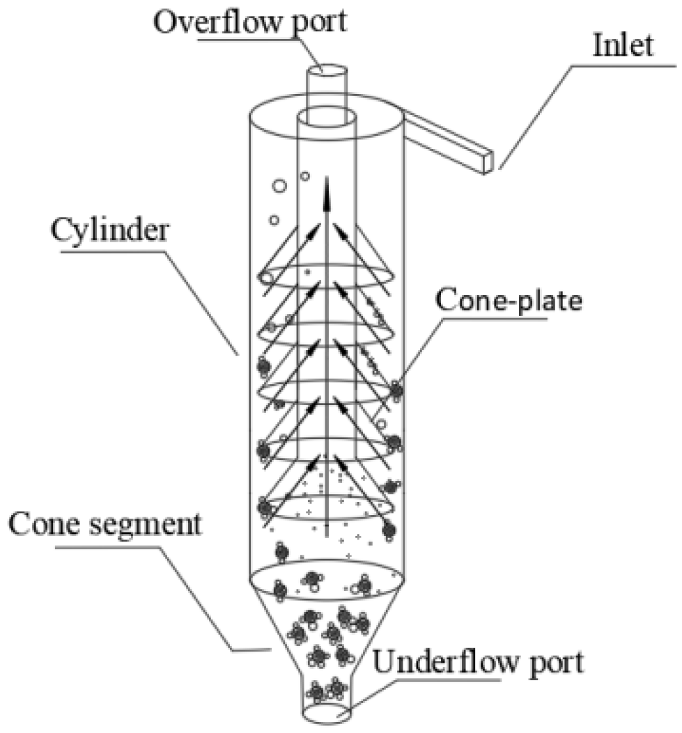
Cone-plate cyclone clarifier is a new type of solid–liquid separation equipment that synthesizes the principle of inclined plate settling and centrifugal settling. Figure 1 is the working principle diagram of the cone-plate cyclone clarifier. Extend the overflow pipe of the cyclone downward, and add a series of cone-plate structures on the outside of the overflow pipe to obtain the traditional cone-plate cyclone clarifier [13]. The role of the cone-plate is to increase the settling area of the particles. Cone-plate cyclone clarifiers not only have a small footprint but also have a large settling area for particles. Therefore, they are suitable for installation in coal mine underground.

Figure 1.
Cone-plate cyclone clarifier working principle diagram.
When the mine water flows tangentially into the cyclone clarifier cylinder from the inlet, the pressure energy is converted into kinetic energy, forming a rotating flow field. Coarse particles and fine particles have different particle sizes and are subjected to different forces such as gravity, centrifugal force, fluid drag force, etc., in the cyclone [14,15,16]. Fine particles are subject to less centrifugal force. A part of the mine water flows through the cone-plate into the overflow pipe and is discharged from the overflow port. Most of the fine particles will be entrained by the mine water and settle on the cone-plate. The centrifugal force acting on the coarse particles is large. The coarse particles are separated by centrifugal force into the outside vortex flow of the cyclone clarifier. Among them, the coarser particles are discharged from the bottom flow outlet under the effect of gravity, and the smaller particles flow into the overflow pipe with the inner vortex flow and are discharged from the overflow port [17,18]. Due to the complex flow field environment inside the cyclone clarifier, it is easy to cause excessive fine particles in the inner vortex flow to overflow [19]. Conventional cone-plate cyclone clarifiers have cone-plate radii of the same size from top to bottom, which does not give full play to the role of the cone-plate. Therefore, equiproportionally varying cone-plate structures are proposed to investigate the effect of cone-plate structure on the effluent quality of the cyclone clarifier.
In this paper, a cyclone clarifier with a gradually shrinking and gradually expanding cone-plate is proposed. The COMSOL turbulence module is used to compare the distribution of streamlines and velocity fields of mine water at different locations in conventional, gradually shrinking, and gradually expanding cone-plate cyclone clarifiers, and theoretically analyze the motion behavior of mine water inside the cyclone clarifier. By coupling the turbulence module with the fluid flow particle tracking module, the motion and separation rows of the particles in three kinds of cyclone clarifiers are visually described. Thus, by further reducing the particle content in the cyclone clarifier overflow and improving the quality of the effluent at the overflow, this paper also provides a new method for improving the cone disc structure of the cyclone clarifier.
2. Numerical Methods
2.1. Geometric Structure
The three-dimensional model of the cone-plate cyclone clarifier is established with the help of SOLIDWORKS 2020 software. Take the center of the bottom flow opening of the cone-plate cyclone clarifier as the coordinate origin. The X-axis points to the direction of the inlet. The Z-axis points to the direction of the overflow pipe.
The gradually shrinking cone-plate cyclone clarifier is an improvement over the cone-plate structure of the traditional cone-plate cyclone clarifier. The cone-plate group adopts an upper large and lower small structure in order to ensure a sufficiently large area of settlement on the basis of a certain proportion of the cone-plate radius being gradually reduced. The purpose is to reduce the number of fine particles inside the cyclone into the overflow pipe, forcing more fine particles for secondary separation.
The gradually expanding cone-plate cyclone clarifier is an inversion of the top and bottom of the cone-plate structure of the gradually shrinking cone-plate cyclone clarifier, and the cone-plate group adopts the top small and bottom large cone-plate structure. The purpose is to verify the effect of the radius of the bottom cone-plate on the separation performance of the cyclone clarifier under the condition that the volume of the cone-plate remains unchanged.
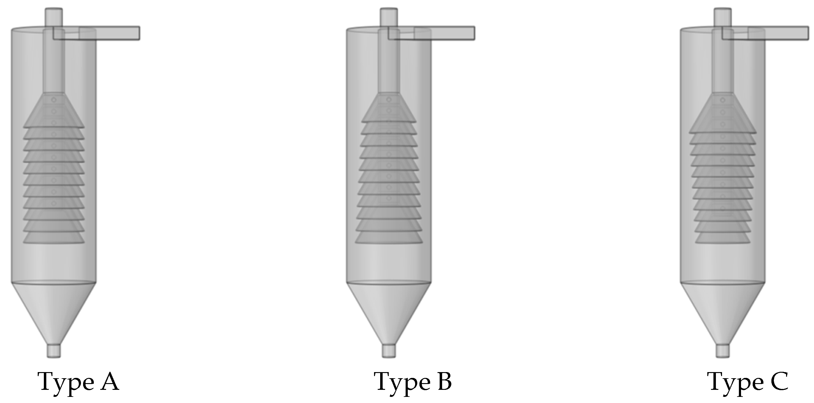
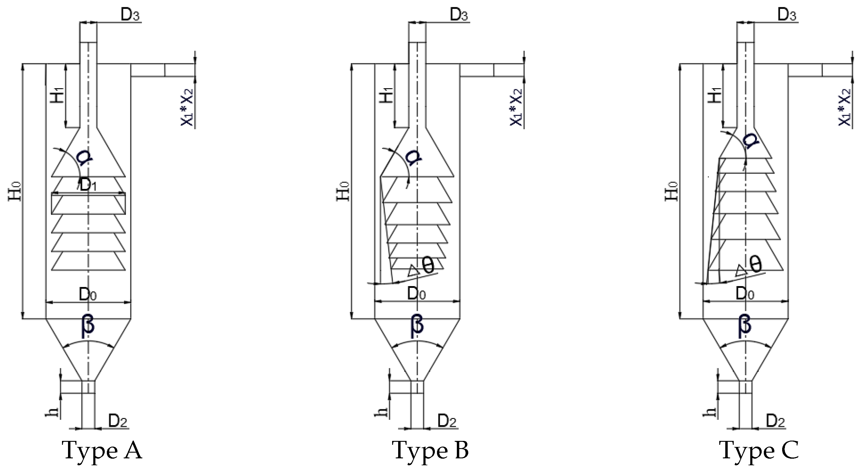
Figure 2 shows the three-dimensional diagrams of three types of cone-plate. Type A is a traditional cone-plate cyclone clarifier. Type B is a gradually expanding cone-plate cyclone clarifier, and Type C is a gradually shrinking cone-plate cyclone clarifier. The dimensional parameters of the different cone-plate configurations are shown schematically in Figure 3. The dimensional parameters are shown in Table 1.
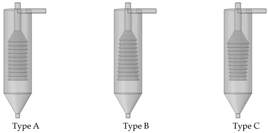
Figure 2.
Three-dimensional drawings of three types of cone-plate rotary clarifiers.
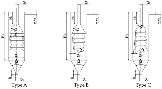
Figure 3.
Schematic dimensional parameters of different cone-plate configurations.

Table 1.
Overall structural parameters of the cyclone clarifiers.
2.2. Model Description
The cone-plate cyclone clarifier has a simple structure, but the internal flow field contains an unpredictable inner and outside vortex flow, etc. The extremely complex flow field poses a serious challenge in predicting particle separation [20,21,22].
With the development of computer technology, computational fluid dynamics is widely used in the study of cyclones [23]. Firstly, the k-ε model is used to simulate the liquid phase, and the flow field of the liquid phase is obtained, which is combined with the theoretical knowledge to predict the cyclone separation. Then, the particle tracking module of the fluid flow is used to obtain the results of the separation of the particles in the liquid phase. For space reasons, only the key equations involved in the model are listed.
The k-epsilon model is a two-equation model under RANS (Reynolds-Averaged Navier–Stokes) that solves two independent transport equations to solve the COMSOl “Turbulence, k-ε” interface which is used to simulate high Reynolds number single-phase flows for both incompressible and low Mach number (typically, <0.3 k-ε) compressible flows. The interface solves the momentum-conserving Navier–Stokes equations and the mass-conserving continuity equations, and turbulence effects are modeled by a standard k-ε two-equation model with realizability constraints. Near-wall flow is modeled using wall functions. It has the advantages of model stability, a fast convergence rate, low memory requirement, and an easy solution, and is widely used in industrial generation.
The turbulent kinetic energy k transport equation is shown below.
The formula for the turbulent viscosity is as follows:
The formula for the generating term is as follows:
The turbulent kinetic energy dissipation rate ε transport equation is as follows:
Here, and are the turbulent Prandtl numbers for the turbulent kinetic energy and turbulent kinetic energy dissipation rate, respectively. The constants in the transport equations as well as in the turbulent viscosity formulation are semi-empirical, and the empirical values derived from the experiments have a good accuracy. = 0.09, = 1.44, = 1.92, = 1.0, and = 1.3.
2.3. Simulation Conditions
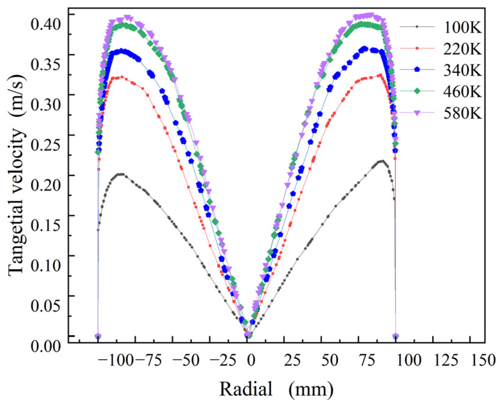
An unstructured grid was used to delineate the cone-plate cyclone clarifier. Grid generation is a prerequisite for simulation to ensure the accuracy of the simulation results while making full use of computational resources, so it is necessary to verify the grid independence [24]. The tangential velocity is selected to verify the grid independence, and the results are shown in Figure 4 The tangential velocity of the mine water increases with the increase in the number of grids, and when the number of grids reaches 4.6 × 10⁵, the tangential velocity does not change with the increase in grids, which proves that continuing to increase the number of grids will not have an effect on the results of the numerical simulation. Therefore, in this study, 4.6 × 10⁵ grids are used as the cells of the computational domain. It contains 273,171 tetrahedral meshes, 16,260 pyramidal meshes, 162,296 prismatic meshes, 46,964 triangular meshes, 160 quadrilateral meshes, 4089 edge cells, and 191 vertex cells.
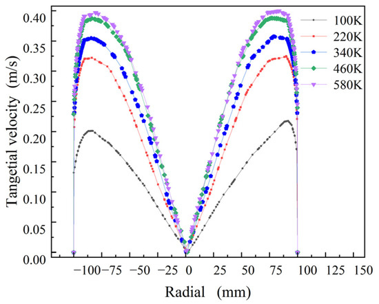
Figure 4.
Grid independence verification.
Set boundary conditions in COMSOL for three types of cone-plate cyclone clarifiers. In the steady state study, the inlet condition of the cyclone clarifier is velocity inlet, which flows along the normal direction, where inlet velocity is 2 m/s. The fluid is incompressible, the material is water, and the density and viscosity of the fluid properties come from the material. The overflow port and the underflow port are pressure outlets; the outlet pressure is 0 MPa, and the wall condition is no slip.
Coal dust in mine water has a small particle size and low content, so only the effect of fluids on solid particles is considered. In the transient simulation, the “fluid flow particle tracking” is coupled to the “k-ε” model, the particle density is set to 1500 kg/m3, the particle sizes are set to 5 μm, 10 μm, 15 μm, and 20 μm, and the particle type is solid. The release starts from moment 0, and the release time is 10 s. Particles with particle sizes from large to small release 5, 10, 15, and 20 particles per second, respectively, and the inlet velocity is based on the velocity field. The overflow and underflow port wall conditions are defined as freezing, and the other wall conditions are defined as rebounding. The drag force is chosen to obey Stokes’ law, the kinetic viscosity and density are according to the material, the velocity is based on the velocity field, the gravity is defined as the Z-axis vertically downward, and the gravitational acceleration is g.
3. Results and Discussion
The three-dimensional model in this paper is based on the original traditional cone-plate cyclone clarifier with an improved cone-plate structure. Due to the unavailability of all post-processing information of the original model, the comparison and discussion of the results will be based on the existing three cone-plate structure cyclone clarifiers.
3.1. Flow Field
The flow field is the carrier of particle movement; changes in the structure of the cone-plate of the cyclone clarifier will inevitably cause changes in the behavior of the flow field, thus affecting cyclone separation of the particles [25,26]. Therefore, the effect of structural changes in the cone-plate of the cyclone clarifier on the flow field is first analyzed. This study will be based on the variation in the flow field in a cyclonic clarifier to predict the trajectory of particles.
3.1.1. Streamline Analysis
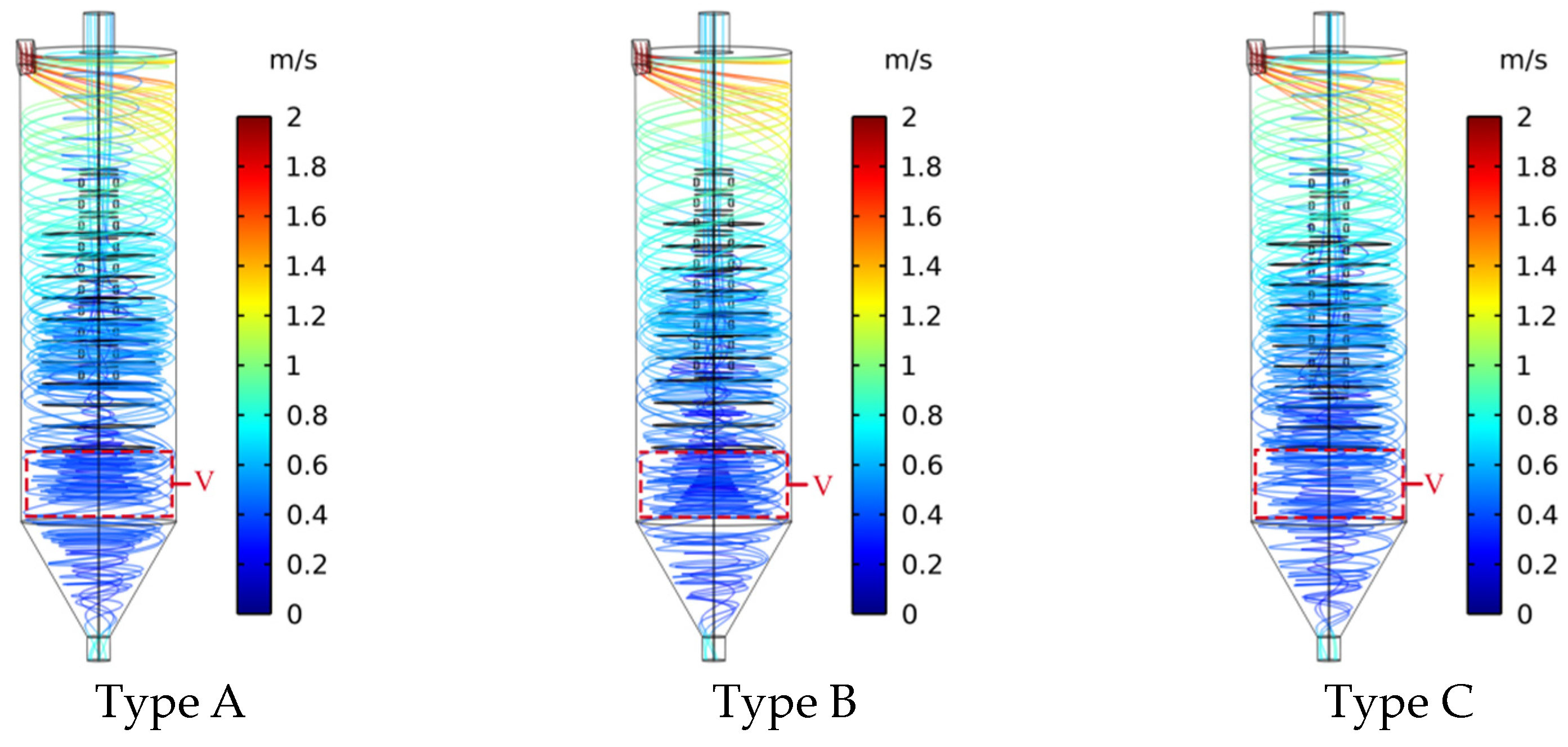
The streamline is a curve tangent to the fluid vector field at an arbitrary position at a certain moment, which applies to the analysis of the results of the fluid flow and can be used with the help of streamlining tools to describe the trajectory of the fluid in the cyclone clarifier. Take the inlet as the positioning boundary of the streamlines and the number of streamlines to be set at 15. The streamline diagrams of fluid in the conventional cone-plate cyclone clarifier, the gradually shrinking cone-plate cyclone clarifier, and the gradually expanding cone-plate cyclone clarifier are shown in Figure 5.

Figure 5.
Flow line diagram of fluid in cyclone clarifiers with different cone-plate structures.
The fluid enters the cyclone clarifier and rotates downwards. A portion of the fluid flows through the cone-plate and is discharged through the overflow port. A portion of the fluid flows downwards after forming an outside vortex flow. A portion of the outside vortex flow is discharged from the underflow port. The rest of the outside vortex flow is restricted by the smaller space in the cone segment of the cyclone clarifier and rotates upwards to form an inner vortex flow, which is discharged from the overflow port. The flow line of the type A cyclone clarifier becomes gradually denser from the top to the bottom. The flow lines are densest at the bottom of the cone-plate group (V zone), which results in most of the fluid in the inner vortex flow flowing directly into the overflow pipe and discharging from the overflow port. Type B cyclone clarifiers have a small upper and large lower cone-plate structure, which intensifies the denseness of the flow lines. There will be more inner vortex flow directly into the overflow pipe and discharging from the overflow port. The type C cyclone clarifier cone-plate adopts the upper large and lower small cone-plate structure so as to make the distribution of the flow line of the fluid in the cyclone clarifier more uniform. In particular, the flow line under the type C cyclone clarifier cone-plate group (V zone) is relatively sparse, indicating that more fluid from the inner vortex flow is able to flow between the cone-plates. Increasing the effective settling area of fine particles in the fluid promotes the secondary settling of fine particles on the cone-plate, reduces the possibility of fine particles entering the overflow pipe, and improves the quality of the effluent.
3.1.2. Analysis of Tangential Velocity
Fluid enters the inlet along the normal direction and then flows tangentially into the cylinder of the cyclone clarifier. The pressure energy possessed by the fluid is transformed into the kinetic energy to support the rotation of the fluid, so the fluid has a certain tangential velocity. The tangential velocity is the largest one among the velocity components of the fluid [27,28]. The centrifugal force acting on the particles is the main driving force for the radial migration of the particles, and the centrifugal force can be expressed as follows:
where is the particle size of the particles, is the density of the particles, and is the tangential velocity of the particles. It can be seen that the centrifugal force on the particles is proportional to the square of the tangential velocity, and the larger the size of the particles and the tangential velocity are, the easier the particles migrate to the outside wall of the cyclone clarifier [29,30].
Figure 6 shows the principle of shallow pool sedimentation in a cyclone clarifier. Va, Vg, and Vt denote the velocities generated by trailing force, gravity, and centrifugal force on the particles, respectively. V0 is the combined velocity of the particles. β is the angle between the combined velocity of the particles and the horizontal direction. α is the angle between the cone-plate and the horizontal direction. When β is less than α, the particles can settle on the cone-plate. All other conditions being equal, the smaller the tangential velocity of the fluid between the cone-plates, the smaller the centrifugal force on the particles, and the more favorable it is for the particles to settle.
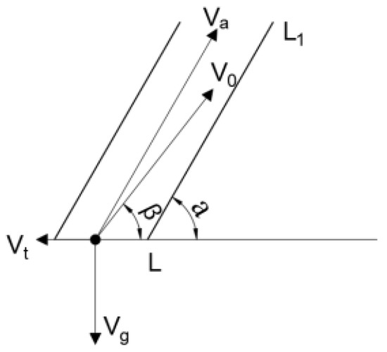
Figure 6.
Principles of shallow pool sedimentation in cyclone clarifiers.
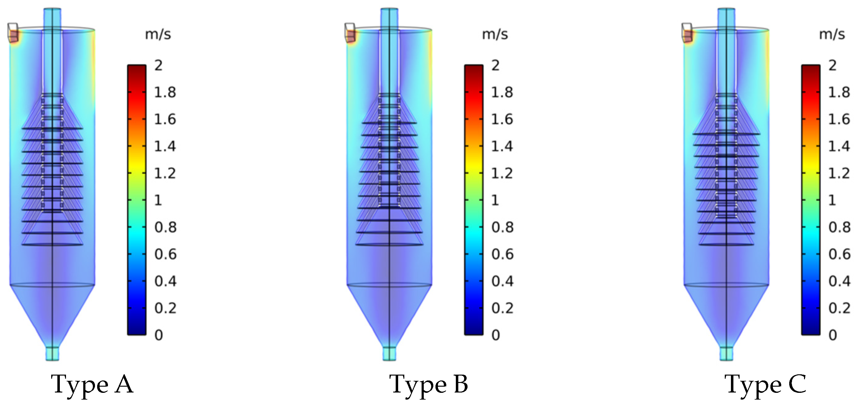
Figure 7 shows the tangential velocity contour of three kinds of cone-plate structure cyclone clarifiers. It can be seen that the tangential velocity contour of the three kinds of cone-plate structure cyclone clarifiers is roughly about the axis in an axisymmetric distribution, and the tangential velocity near the inlet of the column section is the largest. The tangential velocity decreases gradually from the top to the bottom. The larger tangential velocity above the column section near the outer wall of the cyclone clarifier favors particle separation in the radial direction into the outside vortex flow. Smaller tangential velocities between the cone-plates favor particles settling on the cone-plates.

Figure 7.
Tangential velocity contours of fluid in cyclone clarifiers with three cone-plate configurations.
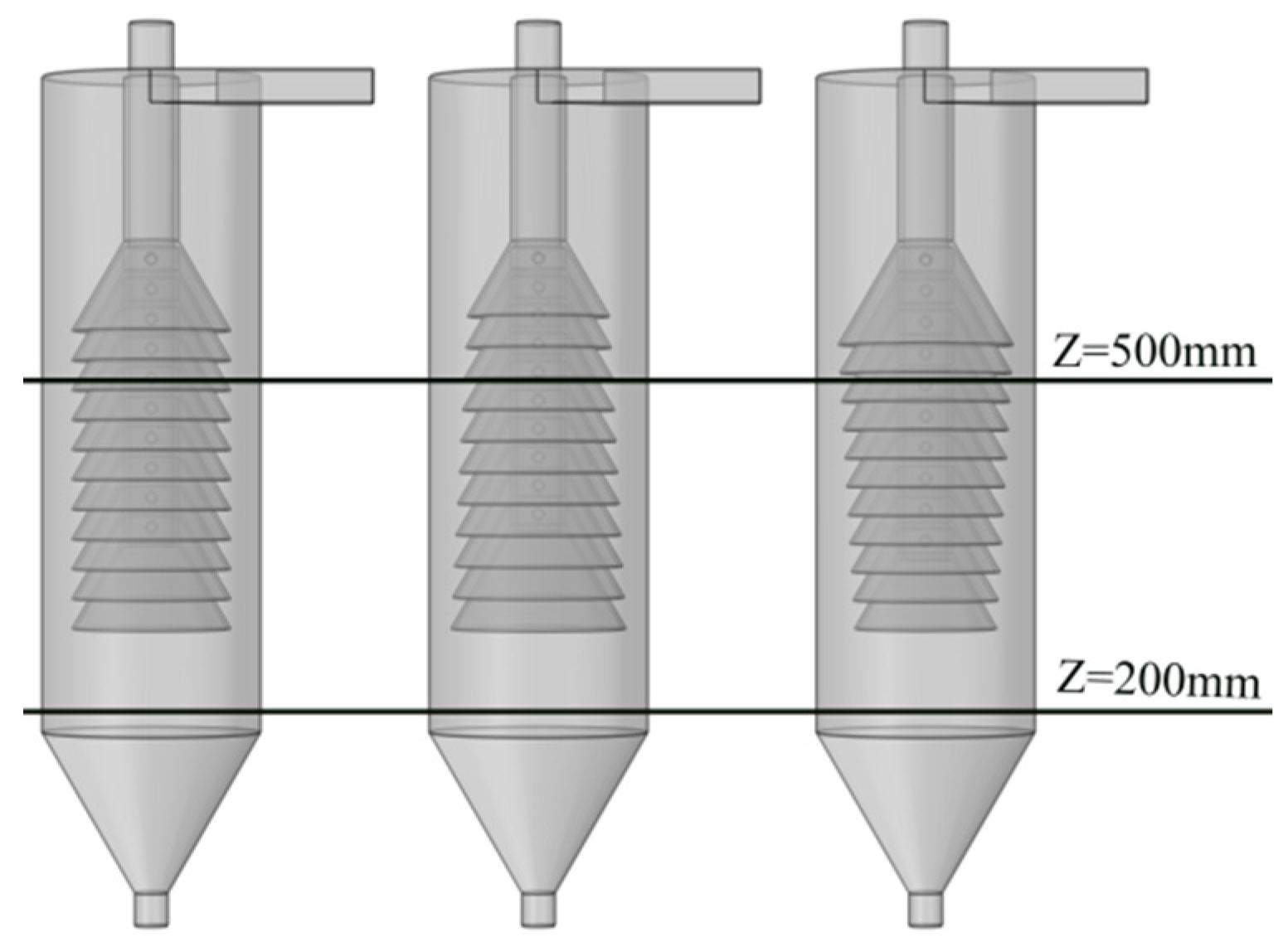
In order to describe in more detail the trend of the velocity change in fluid inside the cyclone clarifiers with different cone-plate structures, the cross-section Z = 500 mm and the cross-section Z = 200 mm were selected to analyze the velocity of the fluid. The location of the cross-sections is shown in Figure 8.
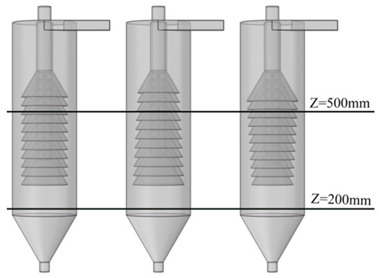
Figure 8.
Cross-sections of cyclone clarifiers at different positions.
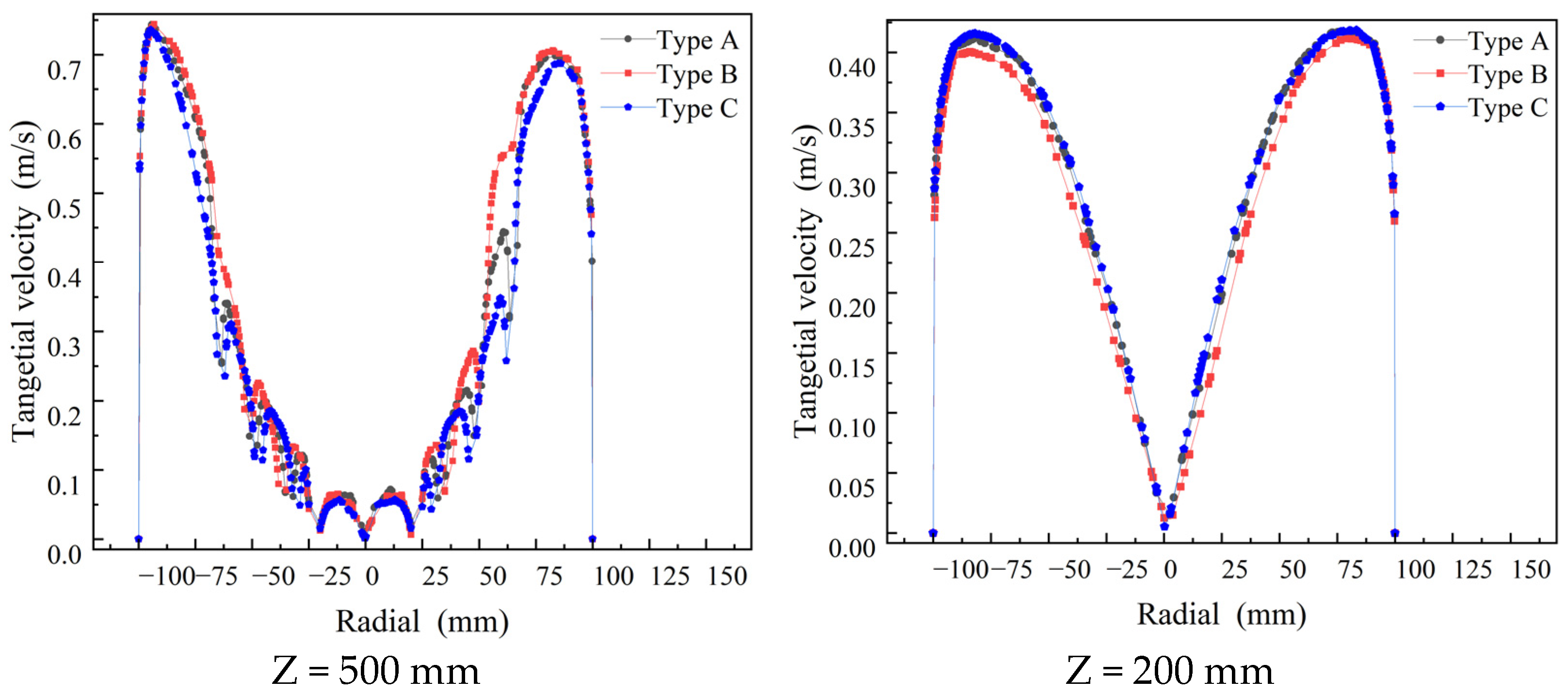
The tangential velocities at the cross-sections are shown in Figure 9. The tangential velocity of the fluid in the cyclone clarifiers with three kinds of cone-plate structures increases rapidly with the decrease in the radius from the wall surface and then decreases gradually. Section Z = 500 mm, due to the existence of the cone-plate, will make the tangential velocity fluctuate within a certain range, but the tangential velocity generally shows a trend of gradually becoming smaller. The tangential velocity in the overflow pipe also increases, then decreases, and reaches the minimum at the center of the axis. The tangential velocities between the plates of the three cone-plate configurations are smallest for the type C cyclone clarifiers and largest for the type B cyclone clarifiers at the cross-section of Z = 500 mm. The small tangential velocity between the cone-plates of the type C cyclone clarifier facilitates the settling of particles on the cone-plates. At the cross-section of Z = 200 mm, the tangential velocity of the fluid in the type C cyclone clarifier is slightly greater than that in the type A cyclone clarifier, and the tangential velocity is the smallest in the type B cyclone clarifier. The larger tangential velocity outside the cone-plate favors the radial separation of particles. Taken together, the cyclone clarifier type C has the strongest cyclone separation ability.
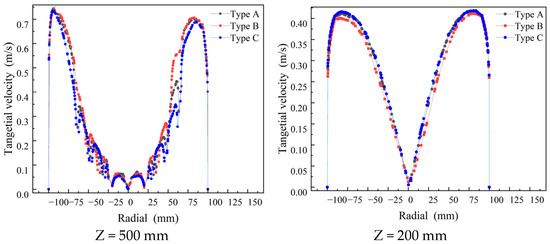
Figure 9.
Comparison of tangential velocity in cyclone clarifiers with three cone-plate configurations of Z = 500 mm and Z = 200 mm sections.
3.1.3. Analysis of Axial Velocity
Axial velocity directly affects the movement direction of particles and the separation time within the cyclone clarifier. The size of the axial velocity determines the settling performance of the particles; smaller axial velocities can prolong the time that the fluid stays in the cyclone clarifier and promote the separation of particles in the fluid [31,32].
Figure 10 shows the axial flow velocity plots for three cyclone clarifiers of cone-plate construction. The axial velocity plots are also roughly axisymmetrically distributed around the axis, with maximum axial velocities near the overflow and underflow ports. Near the outer wall of the cyclone clarifier, the axial flow velocity is negative and the fluid moves downwards. It is outside of the vortex flow and discharges from the underflow port. The axial velocity is positive near the center of the shaft, and the fluid moves upwards. It is inside of the vortex flow and discharges from the overflow port. By the law of fluid continuity, the mass of fluid flowing through a horizontal cross-section remains the same while the inlet flow remains the same, so the larger the cross-section area, the lower the axial velocity. Type C cyclone clarifier in the cone-plate group in the lower position of the cone-plate radius is the smallest, resulting in the maximum cross-sectional area between the cone-plate and the outer wall of the cyclone clarifier; so, the type C cyclone clarifier in the cone-plate group in the lower position of the axial velocity of the fluid is the smallest. This prolongs the separation time of the particles in the clarifier and promotes the full separation of the particles.
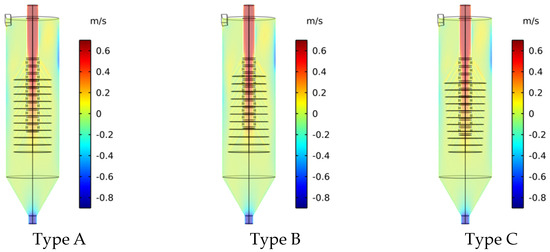
Figure 10.
Axial velocity contours of fluid in cyclone clarifiers with three cone-plate configurations.
Two cross-sections Z = 500 mm and Z = 200 mm were selected to analyze the axial velocity of fluid in three types of cyclone clarifiers with cone-plate structures, as shown in Figure 11. Near the outer wall of the cyclone clarifier with the cross-section Z = 500 mm and cross-section Z = 200 mm, the axial velocity of the fluid in the type C cyclone clarifier is the lowest. This can prolong the separation time of the particles and reduce the number of particles in the overflow port. At the axial position of the cross-section Z = 200 mm, the area where the axial velocity of the fluid in the type C cyclone clarifier is close to 0 is wider. Lower axial velocities allow for adequate separation of particles and improved effluent quality at the overflow port.
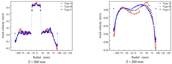
Figure 11.
Comparison of axial velocity of fluid in cyclone clarifiers with three cone-plate configurations of Z = 500 mm and Z = 200 mm sections.
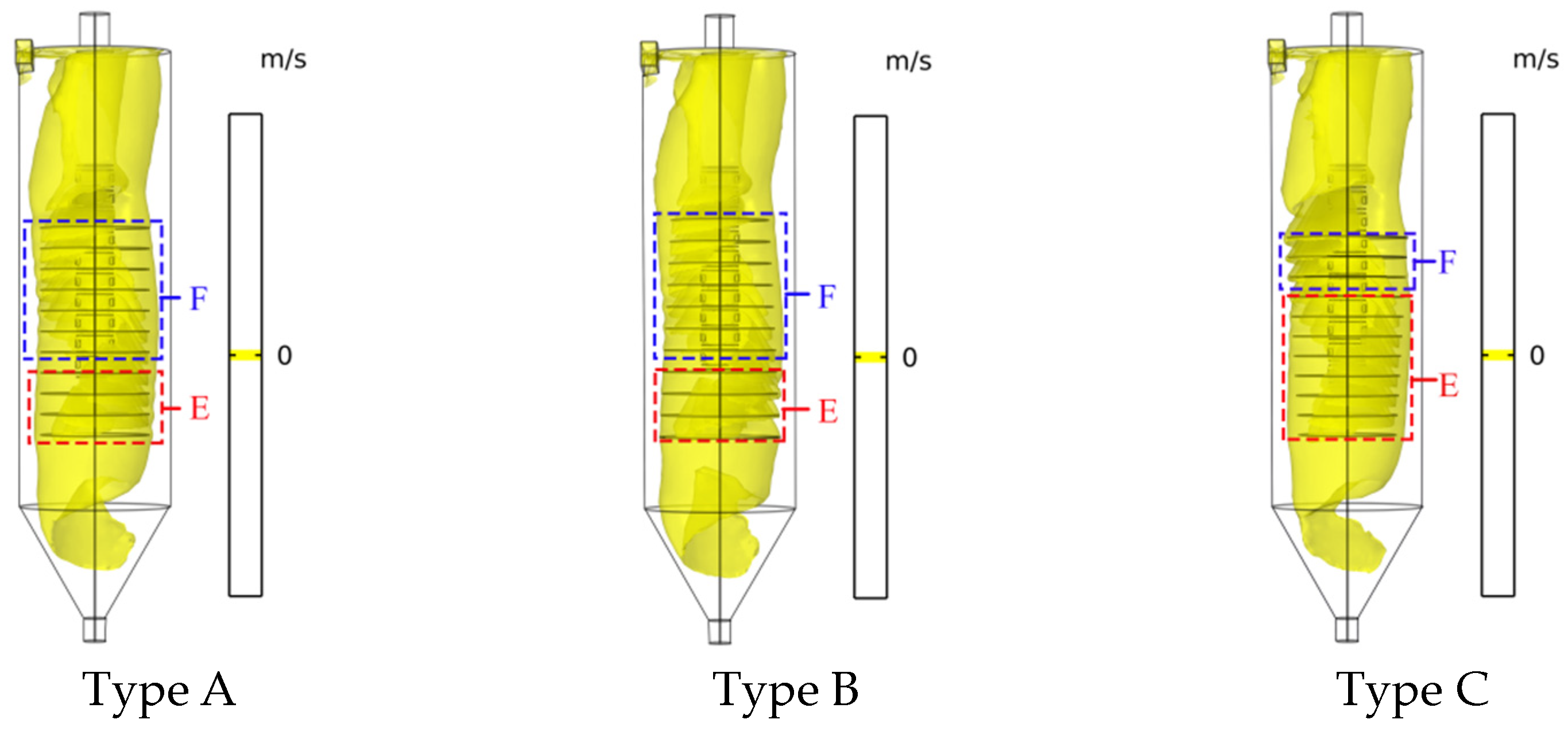
The surface formed by connecting points where the axial velocity is zero is known as the zero-speed envelope surface [33]. Figure 12 shows the zero-speed envelope surfaces of three different cone-plate structures for cyclone clarifiers. Inside the zero-speed envelope surface is the inner vortex flow, and outside the zero-speed envelope surface to the outer wall of the cyclone clarifier is the outside vortex flow.
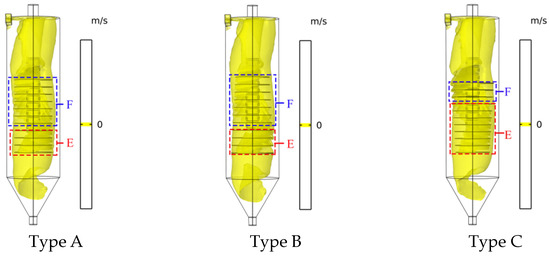
Figure 12.
Clouds of zero-velocity envelope surfaces of fluid in cyclone clarifiers with three cone-plate configurations.
The spacing between the zero-velocity envelope surface of the fluid and the cone-plate in the type A cyclone clarifier is relatively uniform. Fluid enters between the cone-plate and flows upwards, while the fluid near the cone-plate flows downwards. At this time, the direction of axial velocity changes from downwards to upwards, where the formation of zero-velocity envelope surfaces.
The zero-velocity envelope surface of the fluid in the type B cyclone clarifier is more widely spaced from the upper portion of the cone-plate (F zone). This results in larger particles that have not been adequately cyclonically separated flowing into the cone-plate and out of the overflow port. The zero-velocity envelope surface of the fluid in the B cyclone clarifier is less spaced from the lower part of the cone-plate (E zone). The particles in the fluid are sufficiently separated in the vicinity of the E zone, and less fluid flows into the cone-plate (E zone) and is discharged through the overflow port. At the same time, the vast majority of fluids in the inner vortex flow directly to the overflow port without secondary separation, so the quality of the water out of the overflow port is poor.
The spacing between the zero-velocity envelope surface of the fluid and the upper portion of the cone-plate (zone F) is smaller in the type C cyclone clarifier, reducing the likelihood that particles not adequately separated by the cyclone clarifier will enter the cone-plate from the overflow. The spacing between the zero-velocity envelope surface of the fluid and the lower portion of the cone-plate (zone E) is larger in the type C cyclone clarifier. More fluid flows into the cone-plate (Zone E). Here, the particles in the fluid are fully separated. As a result, more fluid enters the overflow pipe, but the number of particles decreases. At the same time, the inner vortex flow portion of the fluid can enter the inside of the cone-plate along the outer edge of the cone-plate, allowing for further settling of the particles in the fluid. The quality of the water discharged from the overflow is greatly improved.
3.1.4. Analysis of Velocity Vector
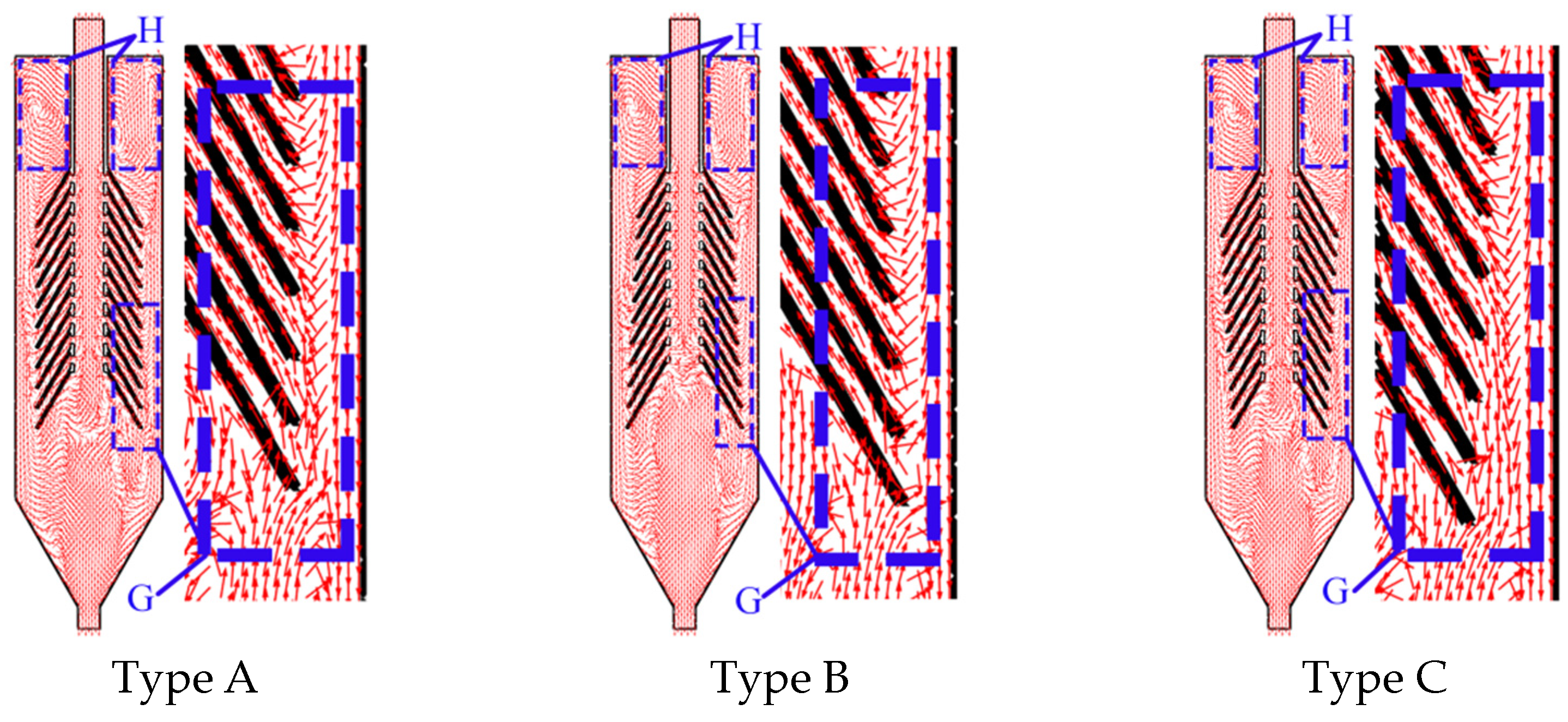
In order to analyze the reasons for the variation in tangential and axial velocities in cyclonic clarifiers with different cone-plate constructions, velocity vectors are introduced, as shown in Figure 13.

Figure 13.
Fluid velocity vectors in cyclone clarifiers with three cone-plate configurations.
After the fluid enters the column section of the cone-plate cyclone clarifier, the fluid will form a circulating flow between the first cone-plate and the top of the cyclone clarifier (H area) due to the cone-plate’s restriction of the fluid’s movement. The fluid rotates downwards under the action of gravity and centrifugal force. As can be seen in the figure, a small amount of fluid flows upwards near the cone-plate at the bottom (G area) of the type A cyclone clarifier and flows into between the two cone-plates. The fluid flowing between the two cone-plates of the downside position of the cone-plate group is mainly from the inner vortex flow, while the fluid flowing between the two cone-plates of the upper portion of the cone-plate group is mainly from the outside vortex flow. The cone-plate at the bottom of the type B cyclone clarifier has a large radius, and the inner vortex flow basically flows to the overflow pipe. The fluid flowing between the cone-plates is mainly from the outside vortex flow. The type C cone-plate cyclone clarifier has the smallest radius of the cone-plate at the bottom. More inner vortex fluid is able to flow between the middle and lower portions of the cone-plate set for particle settling. Fluid flowing into the cone-plates of the upper portion of the cone-plate group is mainly from the outside vortex flow. The larger tangential velocity in the type C cyclone clarifier at the following positions of the cone-plate group also results in a larger centrifugal force on the particles in the inner vortex flow. This causes more particles to flow between the two cone-plates (G zone) and promotes the secondary settling of fine particles. The greater inner vortex flow on both sides of the cone-plate of the type C cyclone clarifier generates a higher energy loss by interacting with the outside vortex flow. This reduces the tangential velocity of the type C cyclone clarifier in the vicinity of the cone-plate. It also reduces the axial velocity near the outer wall of the cyclone clarifier. This is consistent with the previous analysis.
3.2. Particle Tracking
Simulation of the flow field only qualitatively analyzes the movement of particles in the cyclone clarifier. In order to visualize the number, position, and velocity of the particles in the cyclone clarifiers with different cone-plate structures at each moment, transient simulations of fluid were carried out with the aid of the COMSOL particle tracking module.
In the post-processing work, the optimization of the structural parameters of the cyclone clarifier was greatly assisted by the addition of particle counters to count the number of particles flowing through the bottom of the cone-plate and the bottom of overflow tube to the overflow port. Figure 14 shows the velocity distributions of particles of 10 μm size in the three cone-plate cyclone clarifiers in the transient simulation.
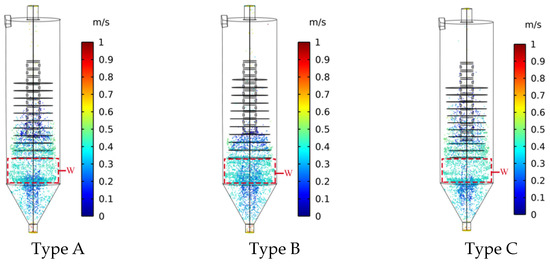
Figure 14.
Particle velocity contours in cyclone clarifiers with three cone-plate structures.
The particles in the type A cyclone clarifier are mainly settled between the two cone-plates of the lower half of the cone-plate group, and the upper half of the cone-plate group is not fully utilized, thus not giving full play to the settling performance of all of the cone-plates. At the same time, the fine particles that fail to settle enter the inner vortex flow in the W zone with a higher number of particles, resulting in a higher number of fine particles flowing out through the overflow pipe. The particles in the type B cyclone clarifier are mainly settled between the two cone-plates of the lowest three cone-plates; these cone-plates cannot be fully utilized, further aggravating the phenomenon. The W area of the inner vortex flow into the overflow pipe and through the overflow port discharge of the number of particles is further increased. The number of particles settling between the cone-plates in the type C cyclone clarifier are more uniform, and the settling performance of each cone-plate can be fully utilized. The number of particles entering the overflow pipe in W area of the cyclone are reduced, which improves the quality of the water discharged from the overflow.
The number of particles in the overflow are a direct reflection of the capacity of the cyclone clarifier to treat mine water. Figure 15 is a graph of the number of particles in the overflow port as a function of time. The number of particles in the overflow port of the type A cyclone clarifier basically remained unchanged after about 31 s. The number of particles in the overflow port of the type B cyclone clarifier remained unchanged until 34 s. The number of particles in the overflow of the type C cyclone clarifier remained unchanged after about 25 s. The number of particles in the overflow of the type C cyclone clarifier are much smaller than those of the type B cyclone clarifier, and the number of particles in the overflow of the type A cyclone clarifier are in between type B and type C.
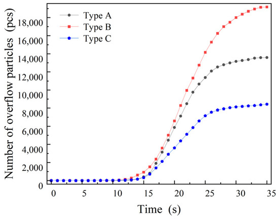
Figure 15.
Plots of particles at the overflow of cyclone clarifiers with three cone-plate structures as a function of time.
The fluid contains particles with four particle sizes of 5 μm, 10 μm, 15 μm, and 20 μm. Figure 16 shows the number of particles of different particle sizes at the overflow port in three cone-plate configurations of cyclone clarifiers. In the three cone-plate structure cyclone clarifiers, the number of small particles at the overflow are the highest, and the number of particles decrease as the particle size increases. This indicates that large particles are more easily separated and settled by centrifugal force and gravity. The type B cyclone clarifier has the highest number of 5 μm particles in the overflow port, the type A cyclone clarifier has the middle number of 5 μm particles in the overflow port, and the type C cyclone clarifier has the lowest number of 5 μm particles in the overflow port. The removal efficiency of 5 μm particles at the overflow of the type C cyclone clarifier is 11.51% higher than that of the type A cyclone clarifier. This is due to the small tangential velocity of the fluid between the cone-plates in the type C cone-plate cyclone clarifier, which is conducive to the settling of particles on the cone-plate. In the cyclone clarifier outer wall and near the axis, the type C cone-plate cyclone clarifier in the fluid axial velocity is small and is conducive to the full separation of particles. At the same time, the type C cyclone clarifier adopts the cone-plate structure which is gradually becoming smaller from the top to the bottom, forcing the inner vortex flow particles to flow into the cone-plate for secondary settlement. The number of 20 μm particles at the overflow port of the cyclone clarifiers with the three cone-plate configurations were similar. This is due to the fact that large-sized particles receive high centrifugal force and flow directly out of the underflow port with the outside vortex flow. The cone-plate structure has little effect on the large-sized particles. Type C has increased the removal efficiency of 5 μm, 10 μm, 15 μm, and 20 μm particles by 11.51%, 9.99%, 9.83%, and 7.62%, respectively, compared with that of the overflow of the Type A cyclone clarifier. The removal efficiency of all particles at the overflow of the type C cyclone clarifier was increased by 10.32% compared to the type A cyclone clarifier.
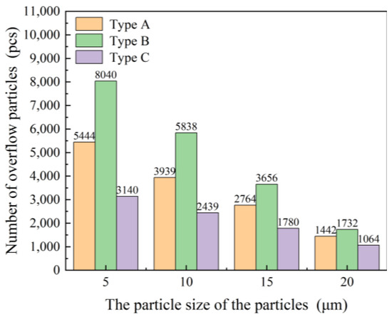
Figure 16.
Number of particles of different sizes in the overflow of cyclone clarifiers with three cone-plate configurations.
4. Conclusions
In this paper, CFD numerical simulation has been used to study the cone-plate cyclone clarifier. The effect of cone-plate radius on the flow field and particle separation performance was analyzed. The following conclusions are drawn:
(1) The change in cone-plate structure has a significant effect on the flow field of the cyclone clarifier. There is poor effluent quality in gradually expanding cone-plate cyclone clarifiers compared to traditional cone-plate cyclone clarifiers. The effluent quality is improved in the gradually shrinking cone-plate cyclone clarifier where particles settle in large numbers on the cone-plate.
(2) The gradually shrinking cone-plate cyclone has a small tangential velocity be-tween the cone-plates, which is favorable for particles to settle on the cone-plates. The gradually shrinking cone-plate cyclone clarifier has a small axial velocity near the outer wall and at the bottom of the cylinder section, which can prolong the time that the mine water stays in the cyclone clarifier and promote the full separation of particles.
(3) The zero-velocity envelope surface and velocity vectors of the three types of cone-plate cyclone clarifiers were analyzed in comparison. Particles in the gradually shrinking cone-plate cyclone clarifier were able to enter between the cone plates for secondary settling.
(4) The gradually shrinking cone-plate cyclone clarifier has the highest removal efficiency for particles. The removal efficiency of all particles at the overflow of the gradually shrinking cone-plate cyclone clarifier was increased by 10.32% compared to the traditional cone–plate cyclone clarifier. The gradually shrinking cone-plate cyclone clarifier, rather than the traditional cone-plate cyclone clarifier, overflow port increased removal efficiency of the 5 μm, 10 μm, 15 μm, and 20 μm particles by 11.51%, 9.99%, 9.83%, and 7.62%, respectively.
Author Contributions
Conceptualization, Y.Z.; data curation, L.X. and J.H.; formal analysis, Y.W.; investigation, Z.Y.; methodology, H.B.; resources, Y.Z.; software, H.B.; validation, K.Z.; visualization, W.D.; writing—original draft, H.B.; writing—review and editing, Y.Z., L.X. and H.B. All authors have read and agreed to the published version of the manuscript.
Funding
This work was supported by the Shandong Natural Science Foundation, China (ZR2023QE121).
Data Availability Statement
Due to privacy concerns, we do not upload our data to the web.
Conflicts of Interest
The authors have declared no conflicts of interest.
References
- Liu, Y.; Liu, P.; Bo, L.; Li, Q.; Quan, G.; Zhuo, Y.; Han, Y.; Wang, Y. Research on Mine Water Dispatching Mode Based on Maximization of Reuse Rate. Sustainability 2022, 14, 9289. [Google Scholar] [CrossRef]
- Wang, X.; Gao, Y.; Jiang, X.; Zhang, Q.; Liu, W. Analysis on the Characteristics of Water Pollution Caused by Underground Mining and Research Progress of Treatment Technology. Adv. Civ. Eng. 2021, 2021, 9984147. [Google Scholar] [CrossRef]
- Guminska, J.; Plewa, F.; Grodzicka, A.; Guminski, A.; Rozmus, M.; Michalak, D. Economic Analysis of the Application of the Technological System for Removing Suspended Solids from Mine Drainage Waters. Energies 2021, 14, 232. [Google Scholar] [CrossRef]
- Wang, K.; Li, Y.; Ren, S.; Yang, P. A Case Study on Settling Process in Inclined-Tube Gravity Sedimentation Tank for Drip Irrigation with the Yellow River Water. Water 2020, 12, 1685. [Google Scholar] [CrossRef]
- Hirom, K.; Devi, T.T. Determining the Optimum Position and Size of Lamella Packet in an Industrial Wastewater Sedimentation Tank: A Computational Fluid Dynamics Study. Water Air Soil Pollut. 2022, 233, 261. [Google Scholar] [CrossRef]
- Peng, Y.; Ni, C.; Tan, J.; Sha, J.; Xie, G. Separation performance of flotation column with inclined plates in the froth zone. Int. J. Miner. Process. 2016, 148, 124–127. [Google Scholar] [CrossRef]
- Garcia, V.A.; Lobato, F.S.; Martins Vieira, L.G. Design of high performance thickener hydrocyclones using robust optimization. J. Pet. Sci. Eng. 2020, 191, 107144. [Google Scholar] [CrossRef]
- Salvador, F.F.; Ascendino, G.G.; de Faria, E.V.; Barrozo, M.A.d.S.; Vieira, L.G.M. Geometric optimization of fi ltering cylindrical hydrocyclones. Powder Technol. 2021, 381, 611–619. [Google Scholar] [CrossRef]
- He, L.; Ji, L.; Sun, X.; Chen, S.; Kuang, S. Investigation of mini-hydrocyclone performance in removing small-size microplastics. Particuology 2022, 71, 1–10. [Google Scholar] [CrossRef]
- Jokovic, V.; Morrison, R.; Alexander, D. Can the performance of semi-inverted hydrocyclones be similar to fine screening? Miner. Eng. 2020, 146, 106147. [Google Scholar] [CrossRef]
- Ji, L.; Paul, P.; Shanbhag, B.K.; Dixon, I.; Kuang, S.; He, L. Emerging application of hydrocyclone in biotechnology and food processing. Sep. Purif. Technol. 2023, 309, 122992. [Google Scholar] [CrossRef]
- Gorobets, A.V.; Tarabara, V.V. Separation performance of desanding and deoiling hydrocyclones treating three-phase feeds: Effect of oil-particle aggregates. Sep. Purif. Technol. 2020, 237, 116466. [Google Scholar] [CrossRef]
- Yang, X.; Liu, P.; Zhang, Y.; Jiang, L. Numerical simulation and experimental study on a cone-plate clarifier. Adv. Mech. Eng. 2019, 11, 1687814019826788. [Google Scholar] [CrossRef]
- Zhao, Q.; Hou, D.; Cui, B.; Wei, D.; Song, T.; Feng, Y. Development of an integrated multichannel inlet for improved particle classification in hydrocyclones. Adv. Powder Technol. 2021, 32, 4546–4561. [Google Scholar] [CrossRef]
- Xiong, Z.; Xu, J.; Liu, C. Interaction effects of inlet velocity and apex diameter on the separation performance of two-stage cone hydrocyclones. Powder Technol. 2023, 422, 118446. [Google Scholar] [CrossRef]
- Liu, L.; Zhao, L.; Wang, Y.; Zhang, S.; Song, M.; Huang, X.; Lu, Z. Research on the Enhancement of the Separation Efficiency for Discrete Phases Based on Mini Hydrocyclone. J. Mar. Sci. Eng. 2022, 10, 1606. [Google Scholar] [CrossRef]
- Goncalves, S.M.; Ullmann, G.; Morimoto, M.G.; de Souza Barrozo, M.A.; Martins Vieira, L.G. Effect of rheology and solids concentration on hydrocyclones performance: A study involving the design variables of an optimized hydrocyclone. J. Pet. Sci. Eng. 2022, 210, 110019. [Google Scholar] [CrossRef]
- Hou, D.; Zhao, Q.; Cui, B.; Wei, D.; Song, Z.; Feng, Y. Geometrical configuration of hydrocyclone for improving the separation performance. Adv. Powder Technol. 2022, 33, 103419. [Google Scholar] [CrossRef]
- Padhi, M.; Mangadoddy, N.; Mainza, A.N.; Anand, M. Study on the particle interaction in a hydrocyclone classifier with multi-component feed blend at a high solids content. Powder Technol. 2021, 393, 380–396. [Google Scholar] [CrossRef]
- de Faria, E.V.; Salvador, F.F.; Ascendino, G.G.; Barrozo, M.A.d.S.; Vieira, L.G.M. Geometric optimization of filtering conical hydrocyclones for thickening purposes with low energy consumption. Chem. Eng. Res. Des. 2022, 178, 168–178. [Google Scholar] [CrossRef]
- Dianyu, E.; Fan, H.; Su, Z.; Xu, G.; Zou, R.; Yu, A.; Kuang, S. Numerical study of the multiphase flows and separation performance of hydrocyclone with tapered cross-section inlet. Powder Technol. 2023, 416, 118208. [Google Scholar] [CrossRef]
- Hou, D.; Cui, B.; Zhao, Q.; Wei, D.; Song, Z.; Feng, Y. Research on the structure of the cylindrical hydrocyclone spigot to mitigate the misplacement of particles. Powder Technol. 2021, 387, 61–71. [Google Scholar] [CrossRef]
- Jiang, J.; Ying, R.; Feng, J.; Wang, W. Computational and Experimental Study of the Effect of Operating Parameters on Classification Performance of Compound Hydrocyclone. Math. Probl. Eng. 2018, 2018, 7596490. [Google Scholar] [CrossRef]
- Jiang, L.; Liu, P.; Zhang, Y.; Yang, X.; Wang, H. The Effect of Inlet Velocity on the Separation Performance of a Two-Stage Hydrocyclone. Minerals 2019, 9, 209. [Google Scholar] [CrossRef]
- Fang, X.; Wang, G.; Zhong, L.; Wang, D.; Qiu, S.; Li, X. Analysis of weakly cemented gas hydrate bearing sediments particles movement and de-cementation behavior in hydrocyclone separator. Powder Technol. 2023, 424, 118174. [Google Scholar] [CrossRef]
- Hou, D.; Zhao, Q.; Liu, P.; Jiang, L.; Cui, B.; Wei, D. Effects of bottom profile on the circulation and classification of particles in cylindrical hydrocyclones. Adv. Powder Technol. 2023, 34, 104050. [Google Scholar] [CrossRef]
- Davailles, A.; Climent, E.; Bourgeois, F.; Majumder, A.K. Analysis of swirling flow in hydrocyclones operating under dense regime. Miner. Eng. 2012, 31, 32–41. [Google Scholar] [CrossRef]
- Wang, Z.B.; Yi, M.; Jin, Y.H. Simulation and experiment of flow field in axial-flow hydrocyclone. Chem. Eng. Res. Des. 2011, 89, 603–610. [Google Scholar] [CrossRef]
- Jiang, L.; Liu, P.; Yang, X.; Zhang, Y.; Wang, H.; Xu, C. Numerical analysis of flow field and separation characteristics in hydrocyclones with adjustable apex. Powder Technol. 2019, 356, 941–956. [Google Scholar] [CrossRef]
- Jing, J.; Zhang, S.; Qin, M.; Luo, J.; Shan, Y.; Cheng, Y.; Tan, J. Numerical simulation study of offshore heavy oil desanding by hydrocyclones. Sep. Purif. Technol. 2021, 258, 118051. [Google Scholar] [CrossRef]
- Kyriakidis, Y.N.; Silva, D.O.; Souza Barrozo, M.A.; Martins Vieira, L.G. Effect of variables related to the separation performance of a hydrocyclone with unprecedented geometric relationships. Powder Technol. 2018, 338, 645–653. [Google Scholar] [CrossRef]
- Liow, J.-L.; Oakman, O.A. Performance of mini-axial hydrocyclones. Miner. Eng. 2018, 122, 67–78. [Google Scholar] [CrossRef]
- Jiang, L.; Liu, P.; Zhang, Y.; Yang, X.; Wang, H.; Gui, X. Design boundary layer structure for improving the particle separation performance of a hydrocyclone. Powder Technol. 2019, 350, 1–14. [Google Scholar] [CrossRef]


Disclaimer/Publisher’s Note: The statements, opinions and data contained in all publications are solely those of the individual author(s) and contributor(s) and not of MDPI and/or the editor(s). MDPI and/or the editor(s) disclaim responsibility for any injury to people or property resulting from any ideas, methods, instructions or products referred to in the content. |
© 2024 by the authors. Licensee MDPI, Basel, Switzerland. This article is an open access article distributed under the terms and conditions of the Creative Commons Attribution (CC BY) license (https://creativecommons.org/licenses/by/4.0/).