Article

Performance of a Double-Filter-Medium Tandem Membrane Bioreactor with Low Operating Costs in Domestic Wastewater Treatment

1
School of Environmental Engineering, Xuzhou University of Technology, No. 2 Lishui Road, Yunlong District, Xuzhou 221018, China
2
Xuzhou Nanwang Water Purification Plant, Xuzhou Jianbang Environmental Water Co., Ltd., No. 75 Yudai Road, Tongshan District, Xuzhou 221148, China
3
Department of Technology, Jiangsu Huichuang Environmental Testing Co., Ltd., No. 7 Jingang Road, Gulou District, Xuzhou 221000, China
*
Author to whom correspondence should be addressed.
Water 2024, 16(2), 361; https://doi.org/10.3390/w16020361
Submission received: 5 December 2023 / Revised: 17 January 2024 / Accepted: 19 January 2024 / Published: 22 January 2024
(This article belongs to the Special Issue Innovative Membrane Processes in Low-Carbon Wastewater Treatment)

Abstract

:
To reduce the operating costs of conventional membrane bioreactors (MBRs) and improve the stability and quality of the dynamic membrane bioreactor (DMBR) effluent, a homemade inexpensive filter cloth assembly was connected to an up-flow ultra-lightweight-medium filter (UUF) in lieu of expensive membrane modules to form a double-filter-medium tandem (DT)-MBR. DT-MBR was used to treat domestic wastewater, and its removal efficiencies for chemical oxygen demand, ammonia nitrogen, total nitrogen, and total phosphorus were similar to those of aerobic MBR, with average removal rates of 91.1%, 98.4%, 15.1%, and 50.7%, respectively. The average suspended solid (SS) of the final effluent was 5.6 mg∙L−1, and the filter cloth assembly played a leading role in SS removal, with an average removal rate of 86.0% and a relatively stable removal effect with little impact via backwashing. The activated sludge zeta potential, flocculation and sedimentation properties, particle size distribution, microbial compositions, extracellular polymeric substances (EPS), and filtration resistance of the cake layer were analyzed; it was found that the cake layer, which can also be called the dynamic membrane (DM), had an excellent filtration performance. However, the DM theory could not reasonably explain why the effluent quality of the filter cloth assembly maintained good stability even after backwashing. The real reason must be related to the sieving of cloth pores. Therefore, the concept of an in situ autogenous static membrane (ISASM) was proposed. With low operating costs and good and stable effluent quality, DT-MBR is a desirable alternative to the traditional MBR.

1. Background

The membrane bioreactor (MBR) has many advantages, including strong biodegradation ability, good and stable effluent quality, less residual sludge, and a small footprint [1,2,3]. It has been widely used in wastewater treatment around the world. The overall treatment capacity of commissioned large-scale MBR projects (with individual treatment capacities ≥ 100,000 m3∙d−1) reached 11,399,000 m3∙d−1 by December 2019. China emerged as a hotspot for MBR applications, with 41 of 62 large-scale MBR projects accounting for 64% of the total treatment capacity [4]. However, membrane fouling remains the most significant barrier to MBR implementation [5].
Membrane fouling mainly refers to colloids, suspended solids (SSs), and soluble substances in the feed solution being adsorbed and deposited on the membrane surface and in the membrane pores, resulting in an increase in filtration resistance and a decrease in membrane flux [6,7,8]. Many factors affect membrane fouling, including but not limited to the nature of the feed solution, such as pH, temperature, mixed liquor suspended solids (MLSSs) and others, membrane material properties, such as pore size and distribution, surface electrical properties, hydrophilicity, and surface roughness, foulant properties and concentration, process operating conditions, such as the sludge retention time (SRT), membrane flux, aeration intensity, and others. Therefore, membrane fouling presents complex characteristics.
Membrane fouling is classified as adsorption, membrane pore clogging, and cake layer fouling based on the interaction of the foulants, membrane, and position. Adsorption fouling is the adsorption of fouling on the membrane surface or the inner wall of the membrane pores as a result of chemical and physical factors. It is related to the charge, hydrophilicity, and solubility of the foulants, as well as the surface electrical performance, hydrophilicity, and adsorption activity point of the membrane materials. Membrane pore clogging fouling is the narrowing or clogging of a membrane pore produced by foulants entering the pore, which is linked to the size of the particles of the foulant and the membrane pore. Cake layer fouling is the aggregation and thickening of foulants on the membrane surface that leads to the formation of a cake layer. It is associated with the foulant’s characteristics, process operating conditions, extracellular polymeric substances (EPSs), microbial traits, and other factors [9].
According to nature, membrane foulants can be divided into organic, inorganic, and biological foulants. These three foulants interact with each other and culminate in a complex membrane foulant. Among them, EPS is identified as the most important substance leading to membrane fouling [10,11,12]. Based on their form, EPS can be categorized into soluble EPS (S-EPS) and bound EPS (B-EPS). Depending on the degree of adhesion, B-EPS can be further divided into a double-layer structure, with an outer layer of loosely bound EPS (LB-EPS) and an inner layer of tightly bound EPS (TB-EPS). This is because B-EPS has a significant impact on the particle size, density, flocculation, sedimentation, and other properties of activated sludge, while the cake layer sludge is primarily composed of activated sludge. As a result, B-EPS has a strong correlation with the filtration of the cake layer. It is thought that the S-EPS has a significant effect on membrane pore clogging. Wang [9] and Jin et al. [13] concluded that the effects of S-EPS and LB-EPS on membrane fouling were much greater than those of TB-EPS.
As EPS is created by microorganisms during metabolism, analyzing the microbial community structure is critical for learning more about EPS and membrane fouling. Liu et al. [10] found that the top four dominant microorganisms in activated sludge were Bacteroidetes, Proteobacteria, Acidobacteria, and Saccharibacteria. The increasing in the first three bacteria and decreasing in the fourth can decrease EPS. Furthermore, Yao et al. [12] demonstrated that adjusting SRT to manage the BOD sludge load could change the structure of the microbial community and lower EPS.
To regain the membrane flux, the membrane modules must be cleaned on a regular basis, making the MBR operation procedure more complex. There are essentially two cleaning methods as follows: one is the physical method, involving hydraulic cleaning, ultrasonic cleaning, etc., and the other is the chemical method, which includes the acid method and alkali method. The physical method is so inefficient that it only removes contaminants that are in loose contact with the membrane. At the moment, the chemical approach is a popular method for membrane fouling recovery. It cannot, however, accomplish efficient and speedy membrane fouling management [14]. Moreover, the chemical approach accelerates membrane aging and reduces the service life of the membrane module. The running cost of MBR is more expensive due to the high cost of the membrane module. High operational expenses are one of the primary barriers to the widespread use of MBR in comparison to the conventional activated sludge process [4]. As a result, numerous studies have been conducted to research and develop innovative solutions for MBR energy conservation and consumption reduction.
Some researchers attempted to replace pricey microfiltration/ultrafiltration membranes with cheap, coarse, porous materials (e.g., filter cloth, nonwoven fabric, nylon mesh, stainless steel). To achieve solid–liquid separation, a cake layer generated on the surface of the coarse porous material was known as the dynamic membrane (DM). As a result, a low-cost, low-energy dynamic membrane bioreactor (DMBR) was developed [15,16,17]. The pore size of coarse porous materials ranged from 10 to 200 um [18]. The DM formation process is divided into three stages, namely, the formation, the stabilization, and the cleaning and regeneration stages [19]. Among them, the formation stage is the process in which the activated sludge is continuously trapped by the coarse porous material, and the cake layer is gradually attached and matured. The stabilization stage mainly refers to the period between the formation of the DM and cleaning and regeneration, which is a really effective process. It not only depends on the DM performance (e.g., thickness, porosity, etc.) but is also affected by operating conditions such as operating pressure, cross-flow velocity, temperature, and aeration intensity [20]. After the DM runs stably for a period, the filtration resistance increases rapidly, the flux decreases rapidly, and it needs to be cleaned and regenerated to restore the filtration performance. The effluent quality of DMBR is unstable because the morphology and structure of DM change constantly during the operation.
To reduce the operating costs of conventional MBR and improve the stability and quality of the effluent, we made a special filter cloth assembly, and a double-filter-medium tandem MBR (DT-MBR) was formed by connecting the homemade inexpensive filter cloth assembly in series with an up-flow ultra-lightweight-medium filter (UUF) in place of expensive membrane modules (Patent application No. 202211152230.0; 202311049563.5). The filter cloth assembly was submerged in the aeration tank to realize solid–liquid separation and the UUF was placed outside the aeration tank for advanced treatment of the filter cloth assembly effluent. DT-MBR was adopted to treat domestic wastewater, and its performance was studied, focusing on organic and nutrient removal.

2. Materials and Methods

2.1. Experimental Setup and Operation Method

The DT-MBR is composed of the aeration tank, air supply pipe, aeration head, filter cloth assembly, peristaltic pump, and UUF. The aeration tank is a stainless-steel cuboid with a length, width, and height of 840 mm, 720 mm, and 1700 mm, respectively, and an effective volume of 0.8 m3. The aeration head is a disc-shaped microporous membrane made of ethylene–propylene–diene monomer (EPDM) rubber with a diameter of 215 mm, and the released bubble is 0.9–1.0 mm in diameter. The self-made filter cloth assembly is composed of a plate frame structure with a double-sided inlet and bottom outlet, the UUF is a DN200 plexiglass column, and the specific characteristics of DT-MBR are shown in Table 1.
Since the filter cloth assembly effluent contains a large amount of gas, it can disturb the filter layer by rising if it enters the bottom of the UUF, resulting in a decline in the filter performance. Therefore, the outlet pipe of the filter cloth assembly is designed as an H-type structure. The opening at the top of the outlet pipe of the H-type filter cloth assembly allows the gas in the water to discharge into the atmosphere, solving the problem of gas in the intake water of the UUF. The structure of DT-MBR is shown in Figure 1.
During the operation, raw wastewater flowed into the aeration tank from the inlet pipe, and air entered the aeration tank through the air supply pipe and the aeration head to supply the dissolved oxygen (DO) necessary for the metabolism of activated sludge. This activated the sludge and sufficiently mixed the substrate. The activated sludge was stopped by the filter cloth, and wastewater containing a small number of SS went through the filter cloth under the suction of the peristaltic pump. Then, it arrived at the bottom of the UUF through the H-type outlet pipe of the filter cloth assembly and reached the top of the filter plate from the bottom up through the filter layer, after which it finally flowed out through the UUF outlet pipe. The working period of the filter cloth assembly and UUF was 24 h and 15 d, respectively. The operational parameters of DT-MBR are shown in Table 2.
An air and water flushing method was adopted to flush the filter cloth assembly, and the specific steps were as follows: (i) The air entered into the interior of the filter cloth assembly through the air flushing pipe to clean the filter cloth from the inside out. The intensity of the air flushing was 1.5 L·s−1∙m−2, and the time was 9 min. (ii) After air flushing, clean water entered into the filter cloth assembly through the water flushing pipe. The water flushing intensity was 1.0 L·s−1∙m−2, and the time was 1 min.
The UUF was flushed by invention patent technology (Patent No. ZL202110930288.2; ZL202110930415.9), and the specific steps were as follows: (i) the air entered into the bottom of UUF through the air flushing pipe and rinsed the filter medium from the bottom up. The intensity of air flushing was 8 L·s−1∙m−2, and the time was 3 min. (2) After air flushing, the UUF was emptied of the rinsing wastewater after 3–5 min. (3) The clean water entered the upper part of the UUF through the water flushing pipe and rinsed the filter medium from the top down, with the water flushing intensity of 4 L·s−1∙m−2 for 3–5 min.

2.2. Raw Wastewater Properties

This experiment was carried out at the Sanbahe Wastewater Treatment Plant (WWTP) in Xuzhou City, where the influent was domestic wastewater. The DT-MBR setup was installed in the inlet bar-screen equipment room of the WWTP, and the fine bar size was 5 mm. The raw wastewater used in this paper was taken from the fine bar-screened effluent, which has substantially lower chemical oxygen demand (COD) and biochemical oxygen demand 5-day test (BOD5) than common domestic wastewater. Thus, it was presumed that the sewage line had been damaged, allowing groundwater to enter and dilute the raw wastewater. Table 3 illustrates the parameters of raw wastewater.

2.3. Analytical Methods

The DT-MBR influent, aeration tank mixture, filter cloth assembly effluent, and UUF effluent were collected two or three times per week. The MLSS, mixed liquor volatile suspended solid (MLVSS), sludge settling velocity (SV30) for 30 min, COD, BOD5, NH4+-N, nitrite-nitrogen (NO2-N), nitrate–nitrogen (NO3-N), TN, and TP were analyzed according to the standard method [21]. Various EPSs were extracted according to the method by Wang et al. [22].
The S-EPS, LB-EPS, and TB-EPS were characterized by the total amount of polysaccharide and protein per gram of MLVSS. Polysaccharide was detected via the anthrone colorimetric method [23]. The protein was detected using the modified Lowry method [24].
The transmembrane pressure (TMP) of the filter cloth assembly was determined using a vacuum gauge. The total resistance of the filter cloth assembly (Rt), the intrinsic resistance of the filter cloth itself (Ri), the pore resistance of the filter cloth (Rp), and the resistance of the cake layer (Rc) were calculated using Darcy’s Law [25].
A model 2100 A turbidimeter (Hach, Ames, IA, USA) was used to detect turbidity. The Litesizer 500 Zeta potential analyzer (Anton Paar, Graz, Austria) was used to determine the zeta potential of activated sludge. The Mastersizer 2000 laser particle size analyzer (Malvern, UK) was used to determine the particle size of activated sludge. The HQ30d DO analyzer (Hach, USA) was used to determine the DO concentration. The HQ11d pH meter (Hach, USA) was used to determine the pH value. The flocculation and sedimentation properties of activated sludge were characterized using the supernatant turbidity (ST) and sludge volume index (SVI), respectively.

2.4. Microbial Community Structure Analysis

Activated sludge samples were taken out from the aeration tank, and the microbial composition in samples was detected and analyzed by Shanghai Personalbio Technology Co., Ltd. through the following steps:
(1)
Illumina Novaseq high-throughput sequencing was performed, and the original data were initially screened, and the problem samples were retested and retested.
(2)
The original sequences, through quality screening, were divided into different libraries and samples according to the index and barcode information, and the barcode sequence was removed.
(3)
Sequence denoising was performed according to the QIIME2 dada2 analysis process, and amplicon sequence variants (ASVs) were obtained. At the same time, the Vsearch analysis method based on operational taxonomic units (OTUs) was retained as an alternative.
(4)
After obtaining ASV/OUT, the sequence length distribution was statistically analyzed to check whether the length of these sequences was comparable to the length range of the target fragment and whether there were sequences of abnormal length.
(5)
The database of Greengenes and the algorithm of QIIME2 classify-sklearn were used to classify the species.
(6)
QIIME2 (2019.4) analysis software, in which the function of QIIME feature–table rarefy, was used to flatten the ASV/OUT abundance table, and the flatting depth was set to 95% of the minimum sample sequence size.
(7)
According to the statistical analysis of the ASV/OTU abundance table, the microbial compositions in each sample can be obtained at the domain, phylum, class, order, family, genus, and species levels.

3. Results and Discussion

3.1. Trend of MLSS

The DT-MBR setup was implemented on 25 May 2022 and lasted more than half a year. The inoculation sludge was taken from the aeration tank of the Sanbahe WWTP in Xuzhou City.
The condensed inoculation sludge was placed into the aeration tank of DT-MBR and then filled with the raw wastewater, and the initial MLSS was 1800 mg∙L−1 on day 1. After that, MLSS increased rapidly, reaching 11,120 mg∙L−1 on day 6. From day 7 onwards, the growth trend of MLSS gradually slowed down and reached 17,720 mg∙L−1 on day 14. From day 15 onwards, 1/30 of the mixture (v/v) in the aeration tank was quantitatively discharged daily to control the SRT at 30 d. MLSS decreased rapidly and eventually stabilized at about 12,000 mg∙L−1. The above trends in MLSS should be compared to the sludge load. Within a certain range, a higher sludge load results in faster MLSS growth rate, i.e., faster microbial proliferation rate. The initial BOD sludge load was 0.1038 kg∙kg−1∙d−1, which decreased to 0.0168 kg∙kg−1∙d−1 on day 6 of the operation and further decreased to 0.0105 kg∙kg−1∙d−1 on day 14 of the operation. The BOD sludge load was 0.0156 kg∙kg−1∙d−1 on day 30 of SRT. The trend of MLVSS was roughly the same as that of MLSS, with MLVSS at an SRT of 30 d at about 4850 mg∙L−1 and the ratio of MLVSS/MLSS at 0.40. Compared with the results of Yao et al. [12], the BOD sludge load in this experiment was low, which could be due to two main reasons. Firstly, the BOD5 concentration of the raw wastewater was only 60.5% that of Yao et al. Secondly, the MLSS in the aeration tank was higher, which was 1.77 times that of Yao et al. Sludge load has a significant effect on sludge sedimentation. The over-high sludge load enables non-filamentous bacteria to dominate, which triggers sludge swelling [26]. However, an over-low sludge load leads to the mass proliferation of filamentous bacteria, which likewise triggers sludge swelling [27,28].

3.2. Solid–Liquid Separation Performance of Filter Cloth Assembly during the Early Operation Period

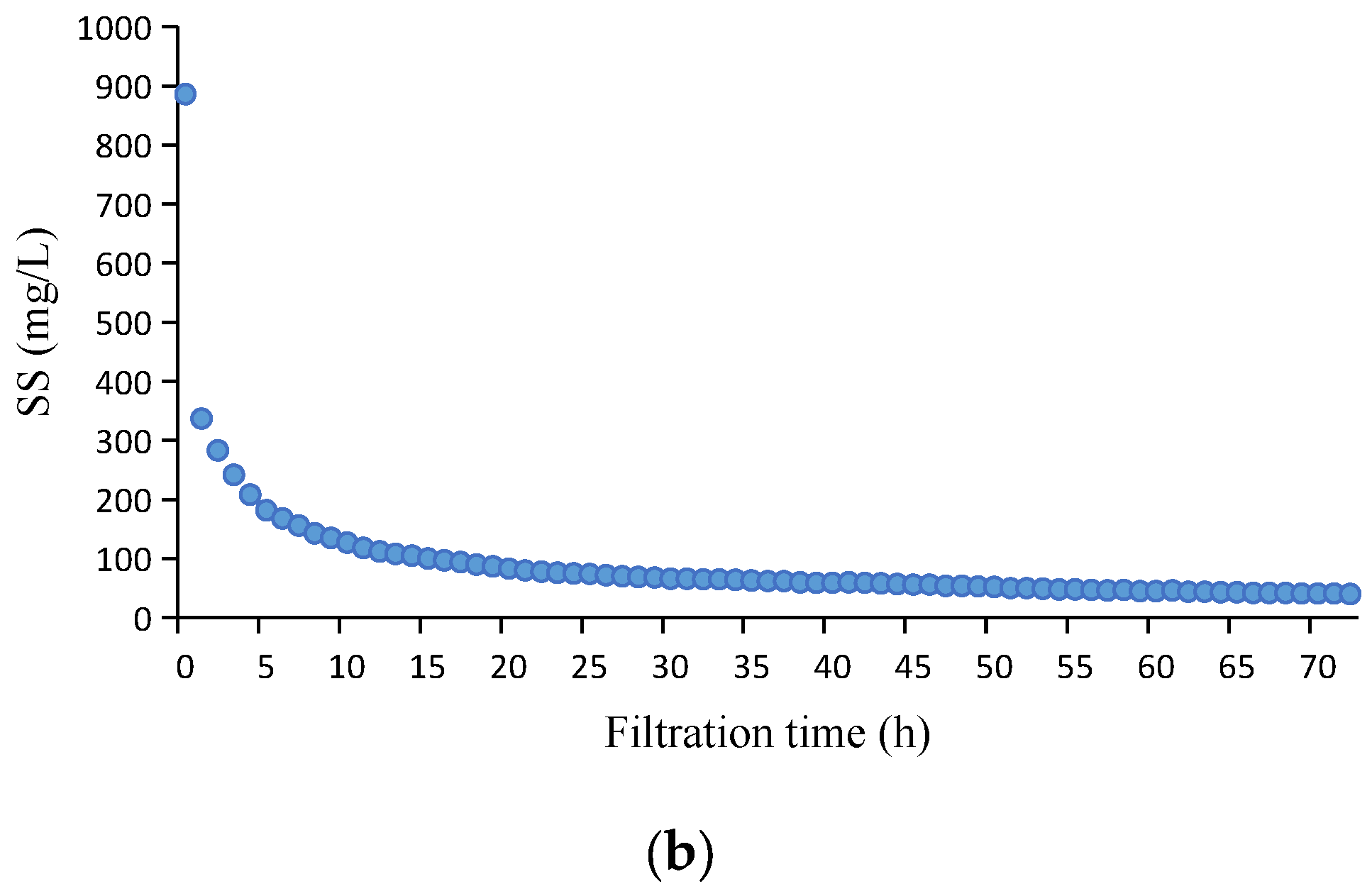
At the initial operation stage, the peristaltic pump was not turned on. The aeration tank operated in the “water inlet-aeration-sedimentation-discharge of supernatant” sequencing batch mode to cultivate the activated sludge. The water inlet time was 0.5 h, with a water inlet volume of about 0.6 m3. The aeration time was 5.5 h, the sedimentation time was 1.0 h, and the supernatant discharge time was 1.0 h. When the MLSS reached 6850 mg∙L−1 on day 5, the peristaltic pump was turned on to pump the effluent, and the complete DT-MBR process was formally in operation. During the operation, the initial effluent turbidity and SS of the filter cloth assembly were remarkably high at 138.5 NTU and 883 mg·L−1, respectively. However, after one hour of filtration, these two parameters decreased rapidly to 47.1 NTU and 337 mg·L−1. With the prolongation of the filtration time, these two parameters were continuously reduced to 6.5 NTU and 80 mg·L−1 at 21 h. Then, the decreasing rate slowed down. At 72 h, the effluent turbidity and SS of the filter cloth assembly were 3.8 NTU and 40 mg·L−1, respectively. The relationship between the solid–liquid separation performance of filter cloth assembly and the filtration time is shown in Figure 2. At the same time, the filtration resistance of the filter cloth increased gradually with the extension of the filtration time. At 72 h, the TMP of the filter cloth assembly was 0.075 MPa, while the Rt was 3.13 × 10¹² m−1.
After 72 h of filtration, the peristaltic pump was deactivated, and the filter cloth assembly was backwashed. After rinsing, the peristaltic pump was turned on again to pump the effluent, at which time the initial effluent’s turbidity and SS of the filter cloth assembly were surprisingly low. The results of multiple repeatability experiments showed that the two parameters were between 4.2–6.4 NTU and 43–78 mg·L−1, respectively. The filter cloth assembly presented a good and stable solid–liquid separation performance. The working period of the filter cloth assembly was adjusted to 24 h to minimize the filtration resistance and reduce the operating cost. The TMP of filter cloth assembly at the end of filtration was 0.06 MPa, with a corresponding Rt of 2.50 × 10¹² m−1. Meanwhile, the Rp was 1.67 × 10¹¹ m−1, and the Rc was 2.33 × 10¹² m−1.

3.3. Performance of Contaminant Removals

After the operation of DT-MBR was stabilized, the raw wastewater, filter cloth assembly effluent, and UUF effluent (also the final effluent of DT-MBR) were collected to detect COD, NH4+-N, TN, TP, SS, turbidity, and other parameters. The turbidity of the raw wastewater was not detected because of the considerable number of SSs with large particle sizes, which interfered with the measurement accuracy of turbidity.

3.3.1. SS Removal

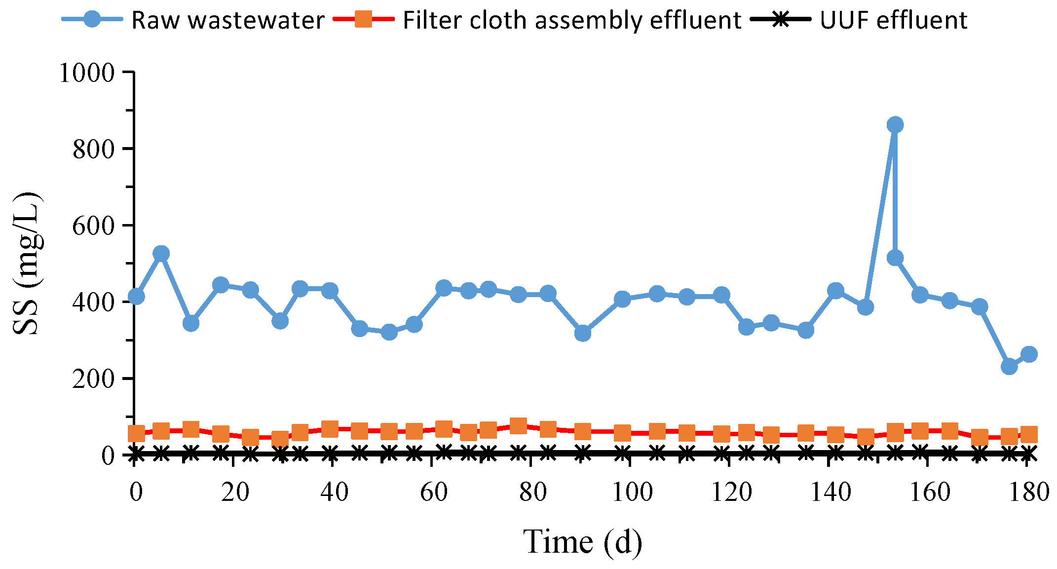
DT-MBR connected the filter cloth assembly in series with the UUF to replace the traditional membrane modules and achieved excellent solid–liquid separation with an average SS removal rate of up to 98.6%. The filter cloth assembly played a leading role in SS removal, with an average removal of 86.0%. The average SS in the effluent of the filter cloth assembly was 58 mg∙L−1, which aligns with the Wastewater Quality Standards for Discharge to Municipal Sewers (GB/T 31962-2015). The average SS in the final DT-MBR effluent was 5.6 mg∙L−1 (Figure 3), which is in accordance with the Discharge Standard of Pollutants for Municipal Wastewater Treatment Plants (GB 18918-2002), Class I-A standard. The average turbidity of the final DT-MBR effluent was 0.7 NTU, which exceeds The Reuse of Urban Recycling Water-Water Quality Standard for Urban Miscellaneous Water Consumption (GB 18920-2002).

3.3.2. COD and NH4+-N Removals

Due to the high MLSS, sufficient HRT, and suitable temperature, DT-MBR presented good biodegradation and nitrification performance with average COD and NH4+-N removals of 91.1% (Figure 4) and 98.4% (Figure 5), respectively, which are similar to those of Liu [10,29] and Münch et al. [30]. The aeration tank played a leading role in COD and NH4+-N removals, with average removals of 79.3% and 84.9%, respectively.

3.3.3. TN Removal

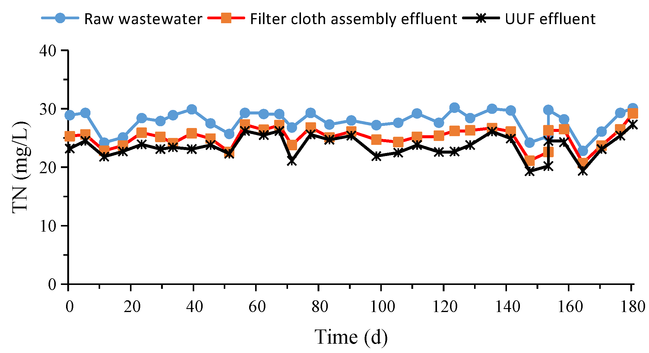
The removal of TN via DT-MBR was poor, with an average removal of only 15.1% (Figure 6). More specifically, the TN removal of 9.7% was obtained using the aeration tank, and the remaining 5.4% was obtained using the UUF. The nitrogen in UUF the effluent was dominated by NO3-N (18.7–26.3 mg∙L−1), which might be related to the DO concentration. The formation of an anoxic zone within the activated sludge floc for denitrification is only possible under low DO and influenced by the mass transfer resistance of oxygen [30,31]. Münch et al. [30] controlled the DO at 0.5 mg∙L−1, Helmer et al. [32] at 1.0 mg∙L−1, and Liu et al. [33] at 0.8–1.1 mg∙L−1, all of which achieved better TN removal. In this experiment, the high DO of the mixture (2.8–4.1 mg∙L−1) did not allow for the formation of an anoxic zone inside the activated sludge floc. Therefore, simultaneous nitrification and denitrification (SND) was not achieved.

3.3.4. TP Removal

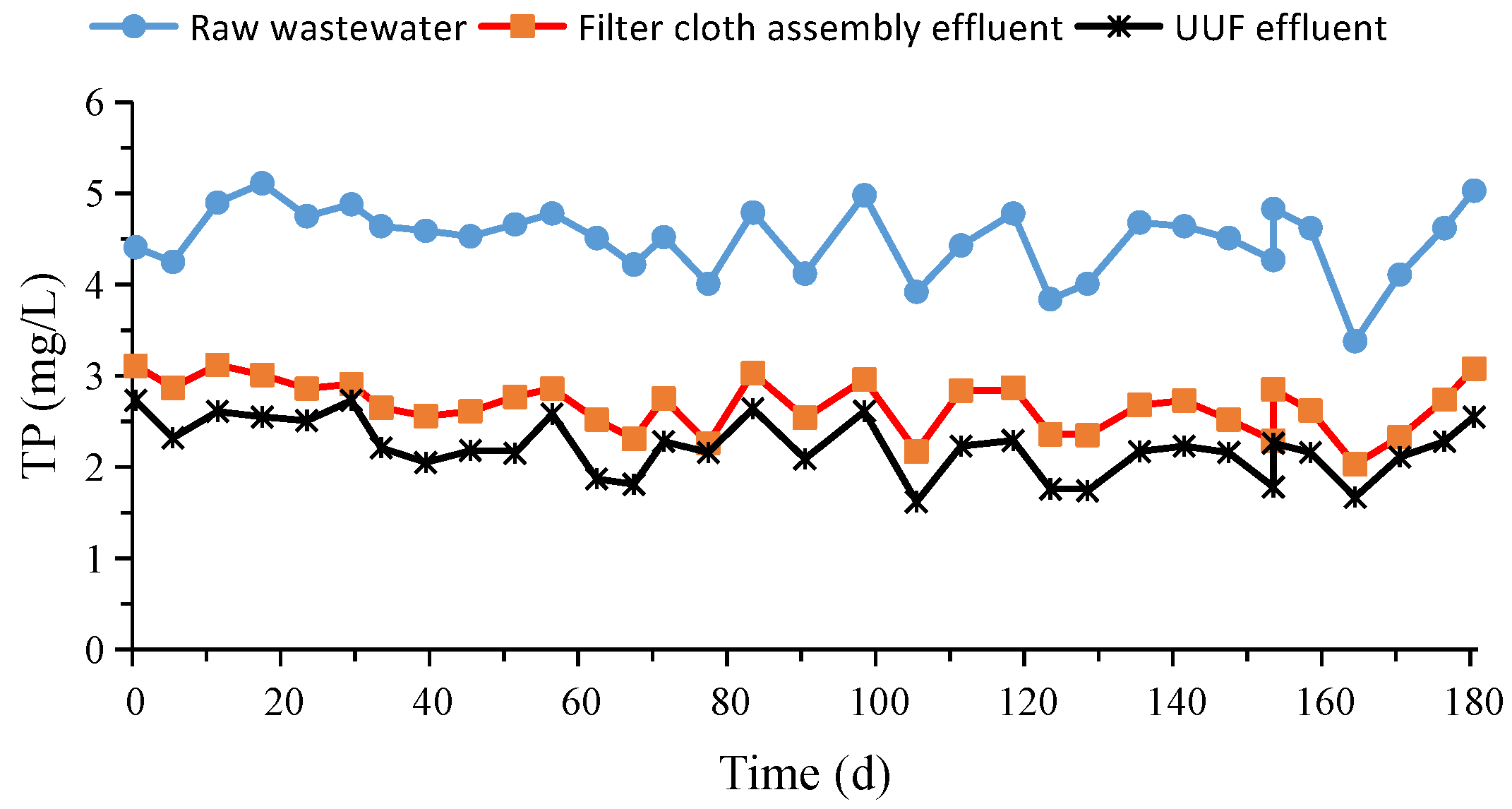
Additionally, due to the high DO, forming an anaerobic zone inside the activated sludge floc as well as in the local area of the aeration tank is difficult, and the phosphorus-accumulating bacteria were unable to conduct the phosphorus-releasing reaction without the anaerobic conditions. Thus, the phosphorus removal efficiency of DT-MBR was poor, and the average TP removal was only 50.7% (Figure 7), which is significantly lower than those of Liu et al. [10,29]. The aeration tank played a leading role in TP removal, with an average removal of 40.4%.

3.4. Property Analysis of Activated Sludge

Wang et al. [9] concluded that changes in activated sludge properties (e.g., particle size distribution, flocculation, sedimentation, and others.) affect the filtration performance of the cake layer. Since Rc is a critical part of Rt, changes in the filtration performance of the cake layer affect the total filtration performance of the filter cloth. Therefore, in order to gain a deeper understanding of the filtration process of filter cloth and correctly analyze the solid–liquid separation mechanism of the filter cloth assembly, the relevant properties of activated sludge in the aeration tank were assessed and analyzed.

3.4.1. Zeta Potential of the Activated Sludge

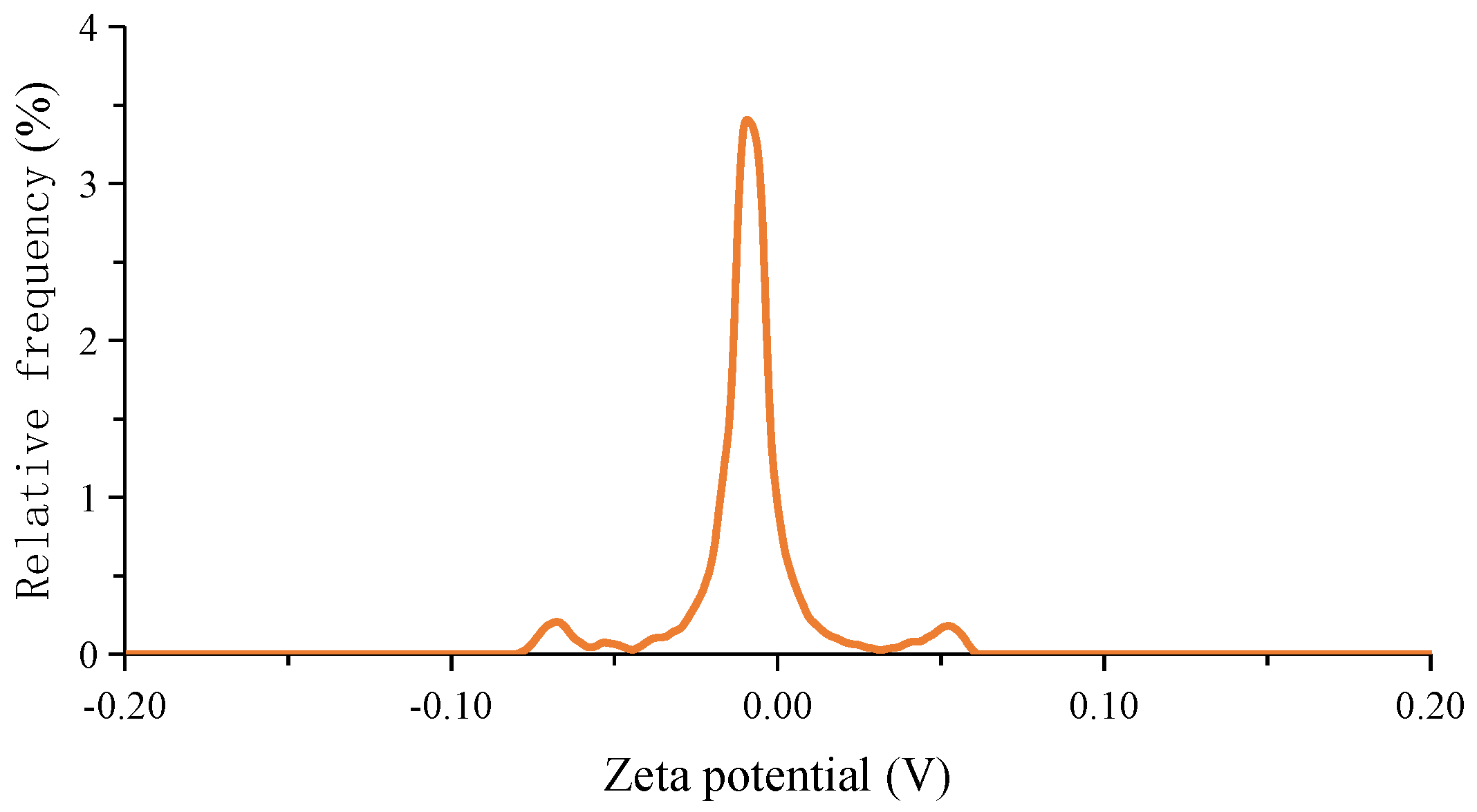
After the DT-MBR operation was stabilized, the activated sludge was taken out from the aeration tank to evaluate its zeta potential. The results are shown in Figure 8. The average zeta potential of the activated sludge was −0.0098 V with a standard deviation of 0.0005 V. According to the diffused double layer theory, and the zeta potential can quantitatively characterize the amount of surface charge in the particles, as well as the magnitude of the electrostatic repulsion between particles, which is important for the formation and stabilization of activated sludge flocs [34,35]. When the number of charges on the particle surface is small, the zeta potential (absolute value) is also low, and the electrostatic repulsion is insufficient to counteract the van der Waals’ force to prevent the particles from coalescing into flocs. When the zeta potential (absolute value) is slower, the repulsive force between particles is slower, and the flocculation of activated sludge under the effect of the van der Waals’ force is better. In general, the zeta potential of activated sludge lies between −10 mV and −25 mV. The zeta potential of activated sludge measured in this paper is low and shows relatively good flocculation. Bobade et al. [36] found that zeta potential decreased with the increasing sludge concentration. Liao et al. [37] came to a similar conclusion that the sludge surface charge decreased with the extension of SRT. The longer SRT of the DT-MBR resulted in a higher MLSS in the aeration tank, which might explain the lower zeta potential in this paper.

3.4.2. Flocculation and Sedimentation of the Activated Sludge

After the DT-MBR operation was stabilized, the flocculation and sedimentation of activated sludge were assessed. The results are shown in Table 4. The average ST of the DT-MBR was 6.3 NTU, which was much lower than that of Wang et al. [9], with an average ST of 8.3 NTU, which could be related to the MLSS. When the MLSS is higher, the zeta potential is lower, and the flocculation of activated sludge is better [36].
The mean SVI of activated sludge was 67.8 mL·g−1, which was much lower than that of Wang et al. [9] with an average SVI of 201 mL·g−1, showing that the activated sludge of DT-MBR has good sedimentation. According to the Derjaguin–Landau–Verwey–Overbeek (DLVO) theory, the surface charge of sludge flocs significantly affects the stability of colloids in the water, and the zeta potential can quantitatively characterize the surface charge of sludge flocs. Steiner et al. [38] found that when the surface charge on the sludge floc was higher, the SVI value was higher. Magara et al. [39] found that the higher the sludge load (i.e., the lower the MLSS), the larger the SVI, which could be related to the surface charge of sludge floc. Liao et al. [37] concluded that there was a correlation between the SRT and the surface charge of sludge floc, which affected the SVI. When the SRT was 4–20 d, the mean SVI ranged from 60 to 85 mL·g−1. Therefore, the better sedimentation of activated sludge in DT-MBR is related to the lower zeta potential of the sludge.

3.4.3. Particle Size Distribution of the Activated Sludge

The activated sludge in the DT-MBR showed a d10 of 4.49 µm and a d90 of 74.45 µm, with an average particle size of 28.52 µm (Figure 9), which was 2.7% smaller than that of Liu et al. [33]. The average particle size of DT-MBR activated sludge was small, but its sedimentation was good, showing that the activated sludge floc had a denser structure.

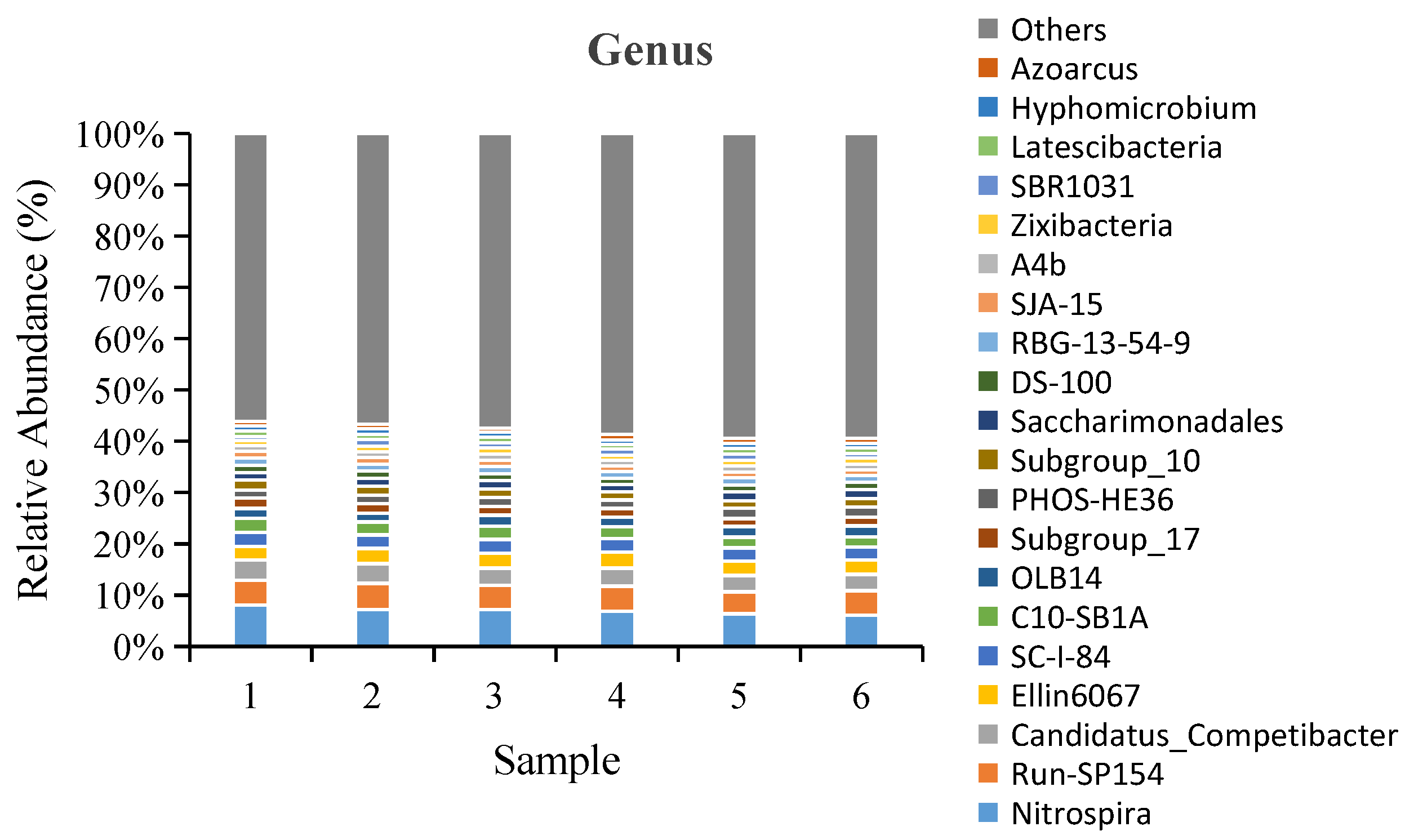
3.4.4. Microbial Community Distribution

When the water temperature was about 23 °C, six activated sludge samples were taken out from the aeration tank at the same time to detect the microbial compositions and select the top 20 dominant genera in relative abundance. The top three dominant genera in the six samples were Nitrospira, Run-SP154, and Candidatus_Competibacter, with an average relative abundance of 6.97%, 4.77%, and 3.50%, respectively (Figure 10). In most WWTPs, Nitrospira is the dominant genus in activated sludge. Under its action, ammonia can be oxidized to nitrite and eventually to nitrate [40,41]. Therefore, DT-MBR achieved a good performance on ammonia removal. Run-SP154 is also a kind of common genus in activated sludge and is believed to contribute to phosphorus removal [42]. Candidatus_Competibacter can secrete exopolysaccharides, which is conducive to the flocculation of microorganisms [43]. However, it can significantly inhibit the removal of phosphorus [44], so the phosphorous removal of DT-MBR is poor.

3.5. Distribution of EPS

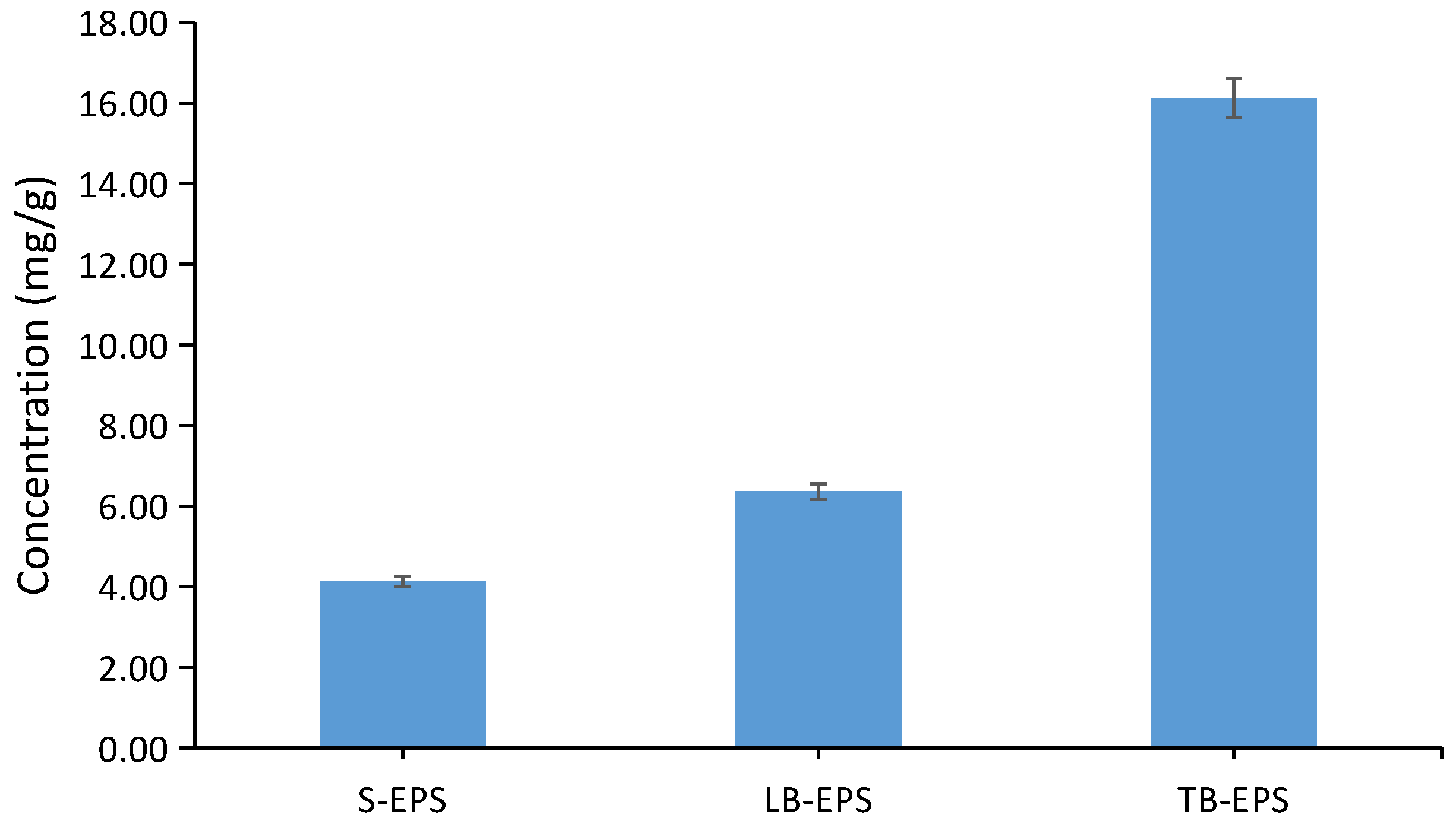
When the DT-MBR operation stabilized, various EPSs were detected. The results are shown in Figure 11. The mean S-EPS, LB-EPS, and TB-EP were 4.13, 6.36, and 16.12 mg·g−1, respectively, which are slightly lower than those of Liu et al. [10] and could be related to the SRT. With different sludge loads under various SRTs, the microbial community structure varies, and the content of EPS naturally differs. Yao et al. [12] concluded that the lowest EPS was found at an SRT of 30 d. EPS covering the surface of microbial cells can improve the flocculation and structural stability of activated sludge by changing the sludge surface properties, hydrophobicity, and surface charge (characterized by zeta potential) [45]. An et al. [46] believed that S-EPS and LB-EPS were negatively correlated with the activated sludge formation and affected sludge flocculation through electrostatic repulsion. Conversely, the TB-EPS positively correlated to the activated sludge formation and promoted its formation through ionic bridging and hydrophobicity. Wang et al. [9,22] also concluded that when S-EPS and LB-EPS were lower, the flocculation and sedimentation of activated sludge improved.

3.6. Proposal of in Situ Autogenous Static Membrane (ISASM) Concept

In this paper, the DM also formed on the surface of the filter cloth. The results show that the zeta potential of activated sludge in the aeration tank was low, the flocculation and sedimentation of the sludge were good, and the size of the floc was small with a dense structure, and these can be related to the appropriate BOD sludge load. Since DM sludge was mainly derived from activated sludge, the improvement of activated sludge improved the filtration performance of DM. In addition, the DM filtration performance was likewise enhanced by the low S-EPS, LB-EPS, and TB-EPS. The Rc on the surface of the filter cloth was 2.33 × 10¹² m−1, which was 44.3% lower than that of conventional MBR [22]. However, the above results cannot supply a reasonable explanation as to why the filter cloth assembly maintained good and consistent solid–liquid separation even after backwashing. According to the DM theory, the DM effluent quality was very unstable during the operation.
The filtration resistance of filter cloth is mainly composed of the cake layer and filter cloth pore resistance, so the filter cloth filtration performance should be related to these two parameters. Since the morphology and structure of the cake layer change during its operation, resulting in the unstable DM effluent quality, the effluent quality of the filter cloth assembly remain good and stable even after backwashing mainly due to the filter cloth pores, for which the concept of ISASM is proposed. Initially, it was believed that after a period of filtration, a layer of lined sludge (i.e., ISASM) with a strong adhesive force was attached to the inner wall of the filter cloth pores, which made the pore size smaller and enhanced sieving. When the pore size was sufficiently small, the sieving of filter cloth pores played a dominant role in solid–liquid separation. Depending on the strength of the adhesion, ISASM can be subdivided into a double-layer structure, with a compact adherent inner layer and a loose adherent outer layer. Among them, the compact adherent layer should be similar to membrane adsorption fouling, while the loose adherent layer should be related to both membrane adsorption fouling and membrane pore clogging. During backwashing, the loose adherent layer falls off under the shear force of the air/water flow, while the morphology and structure of the compact adherent layer remains stable. Therefore, although the pore size of the filter cloth increases slightly after backwashing, the pore sieving remains dominant in solid–liquid separation, which must be the fundamental reason why the effluent quality of the filter cloth assembly remains good and stable even after backwashing.
After detecting and calculating, it was determined that the Ri was 0.84 × 10¹¹ m−1, the Rp before rinsing was 1.67 × 10¹¹ m−1, and after rinsing was 1.39 × 10¹¹ m−1, which might be evidence of the presence of ISASM. Moreover, the strength of air flushing has a significant effect on the filtration of the filter cloth assembly. On the premise of other unchanged conditions, the TMP of the filter cloth assembly was 0.06 MPa at 24 h after rinsing at an air-flush strength of 1.5 L·s−1∙m−2. When the air-flush strength increased to 5.0 L·s−1∙m−2, the TMP of filter cloth assembly at 24 h was only 0.04 MPa, which confirmed the ISASM from another aspect.

3.7. Operating Costs

DT-MBR has low operating costs compared to conventional MBR. The market price of the polyvinylidene fluoride (PVDF) hollow fiber microfiltration membrane module used in our previous studies [9,10,11,12] was in the range of CNY·m−2 90–140. Zhang et al. [4] analyzed some studies in the literature and found that the membrane flux in large-scale MBRs treating municipal wastewater was from 11 to 40 (average of 20.9) L·m−2∙h−1 and the membrane lifespan was from 4 to 7 years (average of 5 years). However, it was also found that the membrane lifespan of 4–5 years was common, and the average price of membrane modules in 2019 was CNY∙ (m3∙d−1)−1 370. According to the data above mentioned, the average price of membrane modules can be converted to CNY·m−2 185.59, which is much higher than those of our previous studies [9,10,11,12]. Jia et al. [47] found that in the actual operation process, large-scale MBRs had serious membrane fouling problems, and the production capacity attenuation was very serious, so it is reasonable to believe that the actual lifespan of membrane modules in those large-scale MBRs is shorter, because by their time of replacement, in this case, the membrane modules must be often overdue for service. In our previous studies [9,10,11,12], it was found that the chemical cleaning period was related to the membrane flux. When the membrane flux was 10 L·m−2∙h−1, the average interval period of chemical cleaning was 4 months, the strength and toughness of membrane filaments significantly declined after chemical cleaning, and the average lifespan of membrane modules was only 2 years. In order to extend the lifespan of membrane modules, we selected the membrane flux of no more than 5 L·m−2∙h−1 in the design of MBRs treating municipal wastewater and no more than 3 L·m−2∙h−1 in the design of MBRs treating municipal landfill leachate.
Meanwhile, the market price of filter cloth assembly is expected to be less than CNY·m−2 20, and it can be run continuously at a flux of 100 L·m−2∙h−1, with a much longer lifespan than that of the membrane module. For example, a filter in Xuzhou Sanbahe WWTP has operated for more than 5 years; the filter cloth presented a good filtration performance and so far has not been replaced. The price of the polystyrene medium in UUF is only half of the same volume as the quartz sand medium, and its lifespan is comparable to that of the quartz sand. In addition, the filtration resistance of filter cloth assembly and UUF are relatively small. Therefore, DT-MBR is a desirable alternative to conventional MBR.

4. Conclusions

This paper introduced a DT-MBR developed by connecting a homemade inexpensive filter cloth assembly in series with a UUF in place of expensive membrane modules; DT-MBR had a good performance for COD and NH4+-N removal but a poor performance for TN and TP removal with average removals of 91.1%, 98.4%, 15.1%, and 50.7%, respectively, which was approximately the same as that of aerobic MBR. The average turbidity and SS of the system effluent were 0.7 NTU and 5.6 mg·L−1, respectively, and the filter cloth assembly played a leading role in SS removal, with an average removal of 86.0% and with little impact by backwashing. The activated sludge zeta potential, flocculation, sedimentation, particle size distribution, microbial compositions, extracellular polymeric substances (EPS), and filtration resistance of the cake layer in DT-MBR were similar to those of conventional MBR; therefore, the DM theory could not rationally explain this phenomenon because the structure of DM would be destroyed after backwashing, and the effluent quality would be worse. The filter cloth’s retention of SS mainly comes from the cake layer and cloth pores. Since the structure of the cake layer was destroyed after backwashing, the reason why the filter cloth assembly maintained stability even after backwashing must be related to the cloth pores, so the concept of ISASM was proposed. We initially believed that, after a period of filtration, a layer of strong adhesive force, less affected by backwashing, and with the relatively stable morphology and structure of the ISASM would attach to the inner wall of the filter cloth pores. Thereby, the sieving of the filter cloth pores occupies a dominant position in solid–liquid separation. Of course, the changes in ISASM-related properties before and after backwashing and the impact on the filtration still need more in-depth research, and the operational stability of the filter cloth assembly also needs to be verified through longer and larger-scale experiments. Due to the low price and high flux of filter cloth assembly and the lower medium price and higher filtering velocity of UUF, DT-MBR can significantly reduce the operating costs associated with the use and replacement of membrane modules and is a desirable alternative to the traditional MBR.

Author Contributions

Conceptualization, Q.L.; investigation, C.L., M.Z., Y.L. (Ying Li), Y.Y., Y.L. (Yuxuan Li) and S.M.; writing—original draft preparation, Q.L.; writing—review and editing, Q.L.; supervision, Q.L.; project administration, Q.L. All authors have read and agreed to the published version of the manuscript.

Funding

This study was financially supported by the Industry-University-Research Cooperation Project of Jiangsu Province (grant number BY2022754); the Key R&D Program of Xuzhou (grant number KC22098, KC19105); and the Science and Technology Deputy General Manager Project of Jiangsu Province (grant number FZ20210338).

Data Availability Statement

The data are contained within this article.

Conflicts of Interest

Author C. Li was employed by Xuzhou Jianbang Environmental Water Co., Ltd. Author M. Zhao was employed by Jiangsu Huichuang Environmental Testing Co., Ltd. The remaining authors declare that the research was conducted in the absence of any commercial or financial relationships that could be construed as a potential conflict of interest.

References

  1. Li, J.Y.; Ren, Y.; Ji, J.; Li, Y.-Y.; Kobayashi, T. Anaerobic membrane bioreactors for municipal wastewater treatment, sewage sludge digestion and biogas upgrading: A review. Sustainability 2023, 15, 15129. [Google Scholar] [CrossRef]
  2. Liu, L.; Zhang, J.; Chen, Y.; Guo, Z.; Xu, G.; Yin, L.; Tian, Y.; Lavrnić, S. Anaerobic fluidized-bed membrane bioreactor for treatment of liquid fraction of sludge digestate: Performance and agricultural reuse analysis. Sustainability 2023, 15, 7698. [Google Scholar] [CrossRef]
  3. Bermúdez, L.A.; Díaz, J.C.L.; Pascual, J.M.; Martínez, M.D.M.M.; Capilla, J.M.P. Study of the potential for agricultural reuse of urban wastewater with membrane bioreactor technology in the circular economy framework. Agronomy 2022, 12, 1877. [Google Scholar] [CrossRef]
  4. Zhang, J.; Xiao, K.; Liu, Z.; Gao, T.; Liang, S.; Huang, X. Large-scale membrane bioreactors for industrial wastewater treatment in China: Technical and economic features, driving forces, and perspectives. Engineering 2021, 7, 868–880. [Google Scholar] [CrossRef]
  5. Qiu, Q.; Gao, M.; Shao, C.; Sun, S.; Liu, Y.; Zhang, H. Copper nanoparticles coupled with fine-powdered active carbon-modified ceramic membranes for improved filtration performance in a membrane bioreactor. Water 2023, 15, 4141. [Google Scholar] [CrossRef]
  6. Asante-Sackey, D.; Rathilal, S.; Tetteh, E.K.; Armah, E.K. Membrane bioreactors for produced water treatment: A mini-review. Membranes 2022, 12, 275. [Google Scholar] [CrossRef]
  7. Wang, C.; Ng, T.C.A.; Ding, M.; Ng, H.Y. Insights of fouling development and characteristics during different fouling stages between a novel vibrating MBR and an air-sparging MBR for domestic wastewater treatment. Water Res. 2022, 212, 118098. [Google Scholar] [CrossRef]
  8. He, H.; Xin, X.; Qiu, W.; Li, D.; Liu, Z.; Ma, J. Role of nano-Fe3O4 particle on improving membrane bioreactor (MBR) performance: Alleviating membrane fouling and microbial mechanism. Water Res. 2022, 209, 117897. [Google Scholar] [CrossRef]
  9. Wang, X.C.; Hu, Y.S.; Liu, Q. Influence of activated sludge characteristics on membrane fouling in a hybrid membrane bioreactor. Desalination Water Treat. 2012, 42, 30–36. [Google Scholar] [CrossRef]
  10. Liu, Q.; Yao, Y.; Xu, D. Mechnism of a membrane fouling control by HMBR: Effect of microbial community on EPS. Int. J. Environ. Res. Public Health 2020, 17, 1681. [Google Scholar] [CrossRef]
  11. Li, Y.; Chen, W.; Zheng, X.; Liu, Q.; Xiang, W.; Qu, J. Microbial community structure analysis in a hybrid membrane bioreactor via high-throughput sequencing. Chemosphere 2021, 282, 130989. [Google Scholar] [CrossRef]
  12. Yao, Y.; Wang, Y.; Liu, Q.; Li, Y.; Yan, J. Mechanism of HMBR in reducing membrane fouling under different SRT: Effect of sludge load on microbial properties. Membranes 2022, 12, 1242. [Google Scholar] [CrossRef]
  13. Jin, B.; Wilén, B.M.; Lant, P. A comprehensive insight into floc characteristics and their impact on compressibility and settleability of activated sludge. Chem. Eng. J. 2003, 95, 221–234. [Google Scholar] [CrossRef]
  14. Le-Clech, P.; Chem, V.; Fane, T.A.G. Fouling in membrane bioreactors used in wastewater treatment. J. Membr. Sci. 2006, 284, 17–53. [Google Scholar] [CrossRef]
  15. Tang, L.; Zhang, J.; Zha, L.; Hu, Y.; Yang, Y.; Zhao, Y.; Dong, X.; Wang, Z.; Deng, W.; Yang, Y. Optimization of critical factors affecting dynamic membrane formation in a gravity-driven self-forming dynamic membrane bioreactor towards low-cost and low-maintenance wastewater treatment. Water 2023, 15, 3963. [Google Scholar] [CrossRef]
  16. Yang, Y.; Deng, W.; Zhang, J.; Dzakpasu, M.; Chen, R.; Wang, X.C.; Hu, Y. A novel precoated anaerobic dynamic membrane bioreactor for real domestic wastewater treatment: In-situ formation, filtration performance and characterization of dynamic membrane. Chem. Eng. J. 2023, 466, 143313. [Google Scholar] [CrossRef]
  17. Chen, L.; Lv, M.; Ding, Y.-C.; Lv, Z.-A.; Ding, D.-N.; Wu, D.; Yuan, H.; Zhu, N.; Feng, H.-J. Investigation of filtration performance and phosphorus removal in an electric field controlled dynamic membrane bioreactor. Chem. Eng. J. 2023, 478, 147328. [Google Scholar] [CrossRef]
  18. Siddiqui, M.A.; Biswal, B.K.; Saleem, M.; Guan, D.; Iqbal, A.; Wu, D.; Khanal, S.K.; Chen, G. Anaerobic self-forming dynamic membrane bioreactors (AnSFDMBRs) for wastewater treatment—Recent advances, process optimization and perspectives. Bioresour. Technol. 2021, 332, 125101. [Google Scholar] [CrossRef]
  19. Hu, Y.; Wang, X.C.; Tian, W.; Ngo, H.H.; Chen, R. Towards stable operation of a dynamic membrane bioreator (DMBR): Operational process, behavior and retention effect of dynamic membrane. J. Membr. Sci. 2016, 498, 20–29. [Google Scholar] [CrossRef]
  20. Li, L.; Xu, G.; Yu, H. Dynamic membrane filtration: Formation; filtration; cleaning; applications. Chem. Eng. Technol. 2017, 41, 7–18. [Google Scholar] [CrossRef]
  21. Rice, E.W.; Baird, R.B.; Eaton, A.D. Standard Methods for the Examination of Water and Wastewater, 23rd ed.; American Public Health Association; American Water Works Association; Water Environment Federation: Denver, CO, USA, 2017. [Google Scholar]
  22. Wang, X.C.; Liu, Q.; Liu, Y.J. Membrane fouling control of hybrid membrane bioreactor: Effect of extracellular polymeric substances. Sep. Sci. Technol. 2010, 45, 928–934. [Google Scholar] [CrossRef]
  23. Raunkjær, K.; Hvitved-Jacobsen, T.; Nielsen, P.H. Measurement of pools of protein, carbohydrate and lipid in domestic wastewater. Water Res. 1994, 28, 251–262. [Google Scholar] [CrossRef]
  24. Frølund, B.; Griebe, T.; Nielsen, P.H. Enzymatic activity in the activated-sludge floc matrix. Appl. Microbiol. Biotechnol. 1995, 43, 755–761. [Google Scholar] [CrossRef]
  25. Lee, J.; Ahn, W.Y.; Lee, C.H. Comparison of the filtration characteristics between attached and suspended growth microorganisms in submerged membrane bioreactors. Water Res. 2001, 35, 2435–2445. [Google Scholar] [CrossRef]
  26. Contreras, E.M.; Giannuzzi, L.; Zaritzky, N.E. Use of image analysis in the study of competition between filamentous and non-filamentous bacteria. Water Res. 2004, 38, 2621–2630. [Google Scholar] [CrossRef]
  27. André, M.V.N.; Jenkins, D.; Richard, M.G. The competitive growth of zoogloea and type 021N in activated sludge and pure culture: A model for low F:M bulking. Water Pollut. Control Fed. 1987, 59, 262–273. [Google Scholar]
  28. Takács, I.; Fleit, E. Modelling of the micromorphology of the activated sludge floc: Low do, low F/M bulking. Water Sci. Technol. 1995, 31, 235–243. [Google Scholar] [CrossRef]
  29. Liu, Q.; Wang, X.C.; Liu, Y.; Yuan, H.; Du, Y. Performance of a hybrid membrane bioreactor in municipal wastewater treatment. Desalination 2010, 258, 143–147. [Google Scholar] [CrossRef]
  30. Münch, E.V.; Lant, P.; Keller, J. Simultaneous nitrification and denitrification in bench-scale sequencing batch reactors. Water Res. 1996, 30, 277–284. [Google Scholar] [CrossRef]
  31. Pochana, K.; Keller, J. Study of factors affecting simultaneous nitrification and denitrification (SND). Water Sci. Technol. 1999, 39, 61–68. [Google Scholar] [CrossRef]
  32. Helmer, C.; Kunst, S. Simultaneous nitrification/denitrification in an aerobic biofilm system. Water Sci. Technol. 1998, 37, 183–187. [Google Scholar] [CrossRef]
  33. Liu, Q.; Wang, X.C. Mechanism of nitrogen removal by a hybrid membrane bioreactor in municipal wastewater treatment. Desalination Water Treat. 2014, 52, 5165–5171. [Google Scholar] [CrossRef]
  34. Wu, D.Q.; Ding, X.S.; Zhao, B.; An, Q.; Guo, J.S. The essential role of hydrophobic interaction within extracellular polymeric substances in auto-aggregation of P. stutzeri strain XL-2. Int. Biodeterior. Biodegrad. 2022, 171, 105404. [Google Scholar] [CrossRef]
  35. Yan, L.; Liu, Y.; Wen, Y.; Ren, Y.; Hao, G.; Zhang, Y. Role and significance of extracellular polymeric substances from granular sludge for simultaneous removal of organic matter and ammonia nitrogen. Bioresour. Technol. 2015, 179, 460–466. [Google Scholar] [CrossRef]
  36. Bobade, V.; Evans, G.; Baudez, J.-C.; Eshtiaghi, N. Impact of gas injection on physicochemical properties of waste activated sludge: A linear relationship between the change of viscoelastic properties and the change of other physiochemical properties. Water Res. 2018, 144, 246–253. [Google Scholar] [CrossRef]
  37. Liao, B.Q.; Allen, D.G.; Droppo, I.G.; Leppard, G.G.; Liss, S.N. Surface properties of sludge and their role in bioflocculation and settleability. Water Res. 2001, 35, 339–350. [Google Scholar] [CrossRef]
  38. Steiner, A.E.; Mclaren, D.A.; Forster, C.F. The nature of activated sludge flocs. Water Res. 1976, 10, 25–30. [Google Scholar] [CrossRef]
  39. Magara, Y.; Nambu, S.; Utosawa, K. Biochemical and physical properties of an activated sludge on settling characteristics. Water Res. 1976, 10, 71–77. [Google Scholar] [CrossRef]
  40. Mehrani, M.-J.; Sobotka, D.; Kowal, P.; Ciesielski, S.; Makinia, J. The occurrence and role of Nitrospira in nitrogen removal systems. Bioresour. Technol. 2020, 303, 122936. [Google Scholar] [CrossRef]
  41. Dueholm, M.K.D.; Nierychlo, M.; Andersen, K.S.; Rudkjøbing, V.; Knutsson, S.; Consortium, M.G.; Albertsen, M.; Nielsen, P.H. MiDAS 4: A global catalogue of full-length 16S rRNA gene sequences and taxonomy for studies of bacterial communities in wastewater treatment plants. Nat. Commun. 2022, 13, 1908. [Google Scholar] [CrossRef]
  42. Chen, H.; Zhou, W.; Xu, Z.; Liu, F.; Feng, P.; Su, L.; Xu, C.; Zhu, S.; Wang, Z. Nitrogen and phosphorus removal by GAOs and PAOs using nitrate and limited oxygen as electron acceptors simultaneously and the impact of external carbon source in the anoxic phase. J. Environ. Chem. Eng. 2021, 9, 106520. [Google Scholar] [CrossRef]
  43. Seviour, T.W.; Lambert, L.K.; Pijuan, M.; Yuan, Z. Selectively inducing the synthesis of a key structural exopolysaccharide in aerobic granules by enriching for Candidatus “Competibacter phosphatis”. Appl. Microbiol. Biotechnol. 2011, 92, 1297–1305. [Google Scholar] [CrossRef]
  44. Whang, L.-M.; Park, J.K. Competition between polyphosphate- and glycogen- accumulating organisms in biological phosphorus removal systems—Effect of temperature. Water Sci. Technol. 2002, 46, 191–194. [Google Scholar] [CrossRef]
  45. Adav, S.S.; Lee, D.-J.; Tay, J.-H. Extracellular polymeric substances and structural stability of aerobic granule. Water Res. 2008, 42, 1644–1650. [Google Scholar] [CrossRef]
  46. An, Q.; Chen, Y.; Tang, M.; Zhao, B.; Deng, S.; Li, Z. The mechanism of extracellular polymeric substances in the formation of activated sludge flocs. Colloids Surf. A Physicochem. Eng. Asp. 2023, 663, 131009. [Google Scholar] [CrossRef]
  47. Jia, F.; Wu, N.; Liu, J. Research and analysis on MBR membrane replacement project of a WWTP in Beijing. China Water Wastewater 2023, 39, 127–133. [Google Scholar]
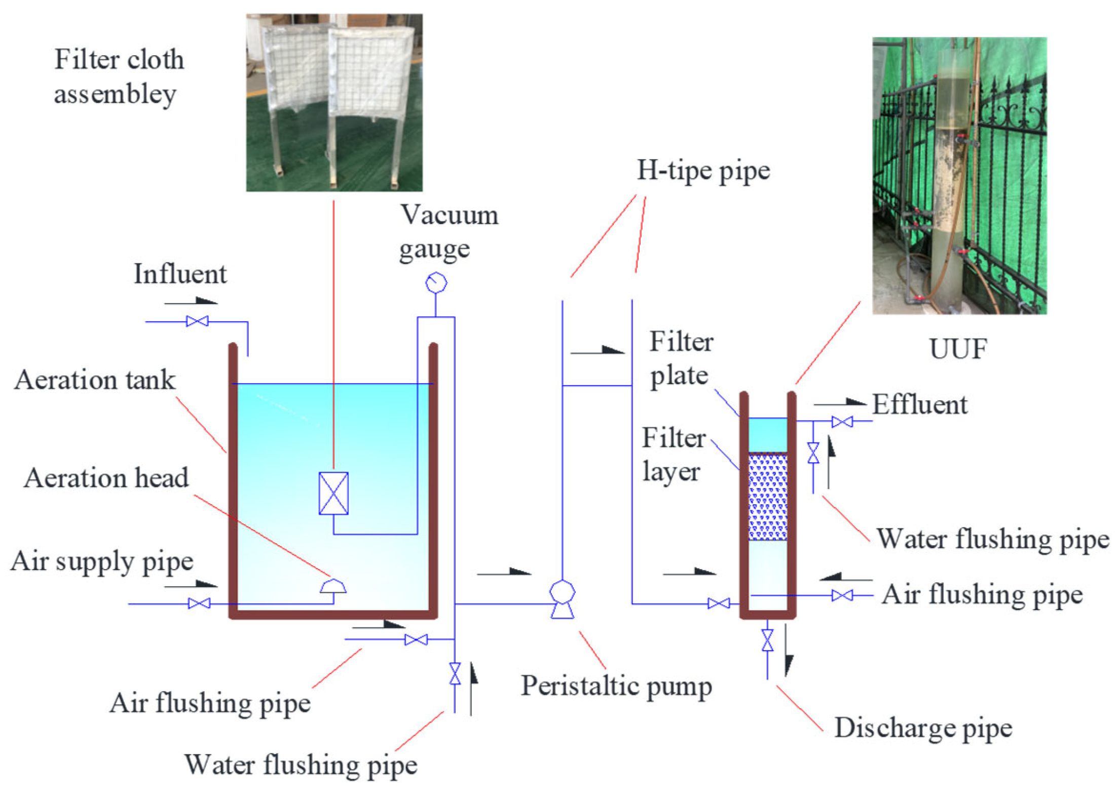
Figure 1. Structure of the DT-MBR.
Water 16 00361 g001
Figure 2. Relationship between the solid–liquid separation performance of filter cloth assembly and the filtration time. (a) Turbidity vs. filtration time. (b) SS vs. filtration time.
Water 16 00361 g002aWater 16 00361 g002b
Figure 3. Performance of SS removal using the DT-MBR.
Water 16 00361 g003
Figure 4. COD removal using the DT-MBR.
Water 16 00361 g004
Figure 5. NH4+-N removal using the DT-MBR.
Water 16 00361 g005
Figure 6. TN removal using the DT-MBR.
Water 16 00361 g006
Figure 7. TP removal using the DT-MBR.
Water 16 00361 g007
Figure 8. Relative frequency distribution of zeta potential of activated sludge flocs in DT-MBR.
Water 16 00361 g008
Figure 9. Particle size distribution of the activated sludge in DT-MBR.
Water 16 00361 g009
Figure 10. Microbial communities at genus level in six activated sludge samples.
Water 16 00361 g010
Figure 11. Various EPSs in the DT-MBR.
Water 16 00361 g011
Table 1. Characteristics of the DT-MBR.
CharacteristicDescription
Length, width and height of the aeration tank (mm)840/720/1700
Effective volume of the aeration tank (m3)0.8
Material of the filter clothPolyester
Length, width and thickness of the filter cloth (mm)769/650/0.95
Total filtration area of the filter cloth (m2)1.0
Air tightness of the filter cloth (L/m2∙s)25
Weight of the filter cloth (g/m2)524
The filter cloth count (count/10 cm2)156/106
Breaking strength of the filter cloth (N/5 × 20 cm)3227/2544
Weaving way of the filter clothPlain weave
Appearance of the UUFPlexiglass column
Diameter of the UUF (mm)200
Height of the UUF (mm)1500
Material of the filter medium in UUFPolystyrene
Particle size of the filter medium in UUF (mm)1.0–2.0
nonuniform coefficient K80 of the filter medium1.17
Thickness of the filter layer in UUF (mm)700
Density of the filter medium in UUF (kg/m3)20
Table 2. Operational parameters of the DT-MBR.
Operational ParameterDescription
Treatment capacity of the DT-MBR (L/h)100
Hydraulic retention time (HRT) of the aeration tank (h)8
SRT of the aeration tank (d)30
Air supply of the aeration system (m3/h)0.4
Filter cloth flux (L/m2∙h)100
Filtration rate of UUF (m/h)3.2
Working period of the filter cloth assembly (h)24
Working period of the UUF (d)15
DO of the MLSS in aeration tank (mg/L)2.8–4.1
Table 3. Raw wastewater properties.
ParameterDescriptionAverage
Temperature (°C)18.3–29.823.3
pH6.6–7.37.1
SS (mg/L)219–1110428
Chemical oxygen demand (COD) (mg/L)76.3–106.898.6
Biochemical oxygen demand 5-day test (BOD5) (mg/L)46.2–74.762.3
Ammonia nitrogen (NH4+-N) (mg/L)21.2–28.725.3
Total nitrogen (TN) (mg/L)22.8–30.227.9
Total phosphorus (TP) (mg/L)3.37–5.114.52
Table 4. Flocculation and sedimentation of activated sludge in DT-MBR.
ST (NTU)SVI (mL/g)
MinimumMaximumAverageMinimumMaximumAverage
6.16.56.363.371.667.8
Disclaimer/Publisher’s Note: The statements, opinions and data contained in all publications are solely those of the individual author(s) and contributor(s) and not of MDPI and/or the editor(s). MDPI and/or the editor(s) disclaim responsibility for any injury to people or property resulting from any ideas, methods, instructions or products referred to in the content.