
A New Type of Pre-Aeration Stepped Spillway

 , ,
, ,
Abstract
:1. Introduction
2. Experimental Setup and Methodology
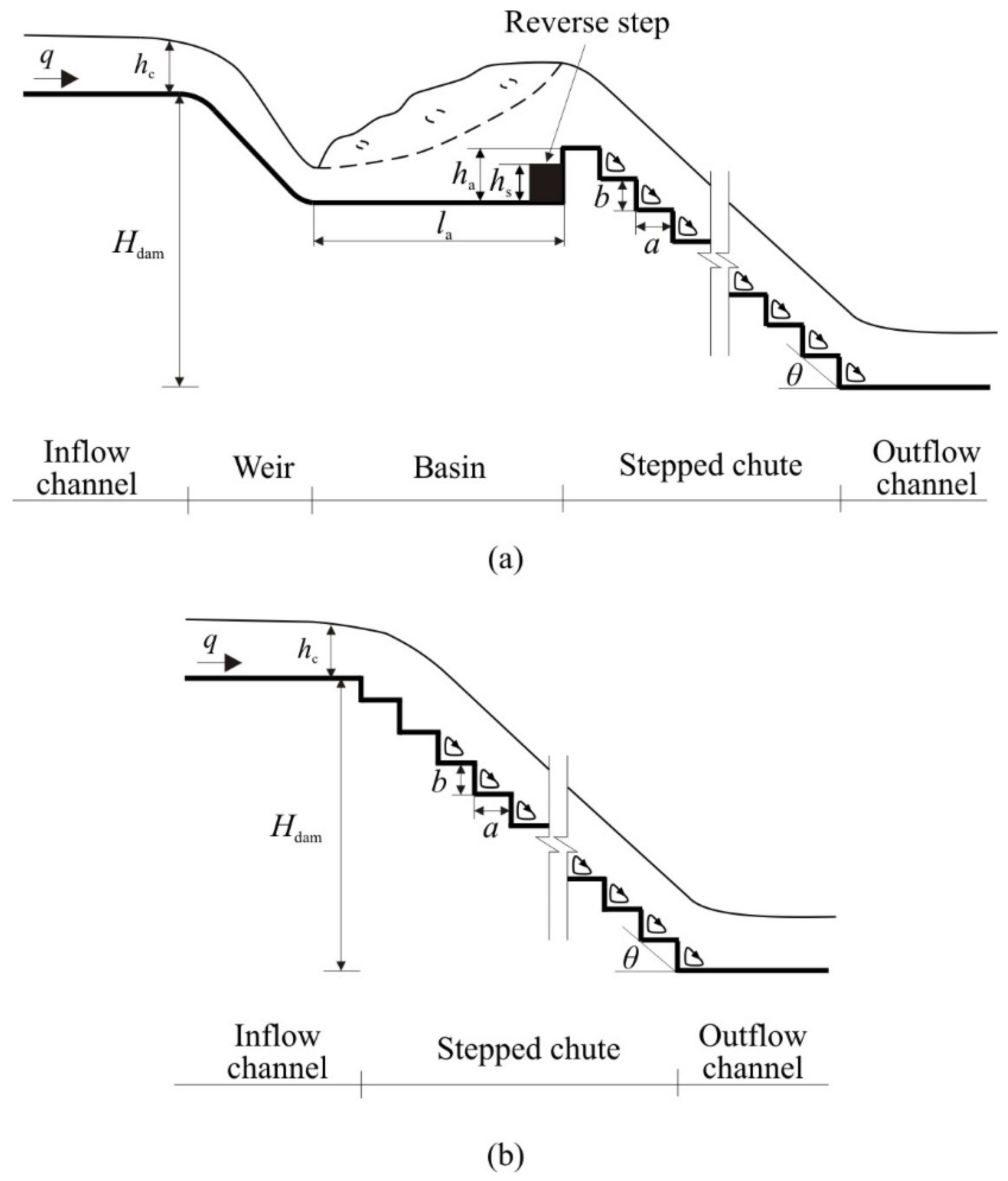
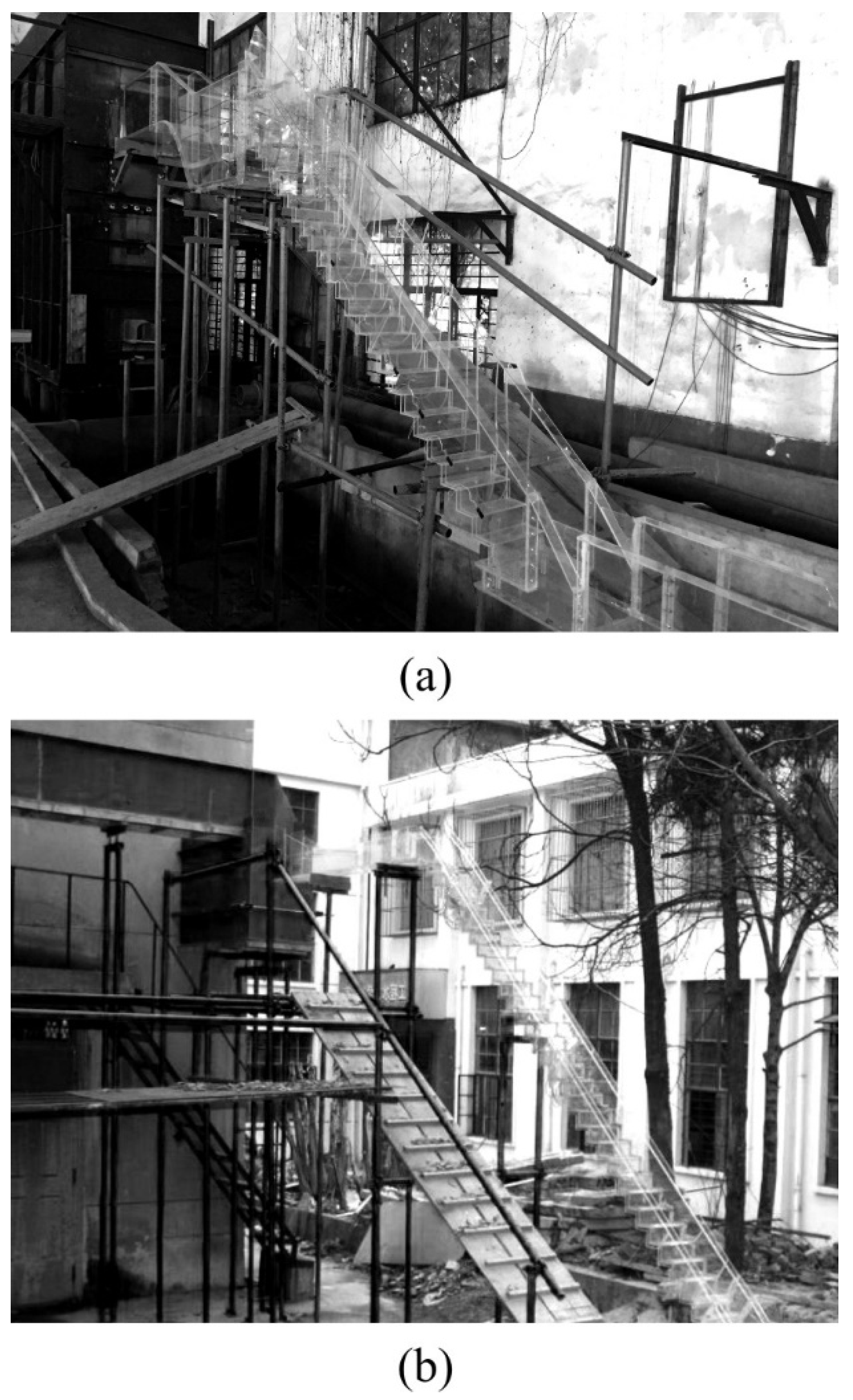
2.1. Experimental Setup
2.2. Experimental Methodology
3. Results and Discussion
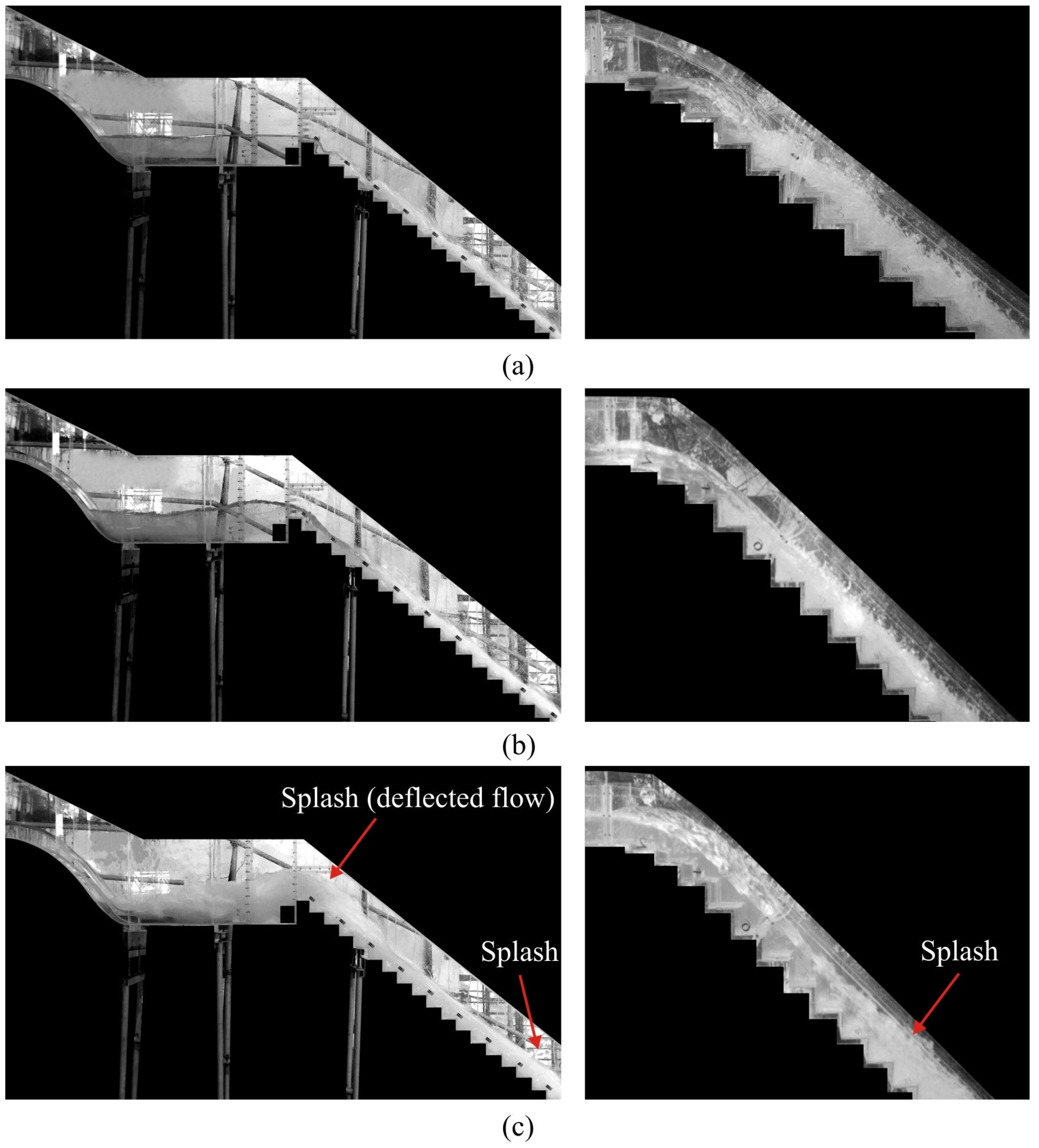
3.1. Flow Pattern
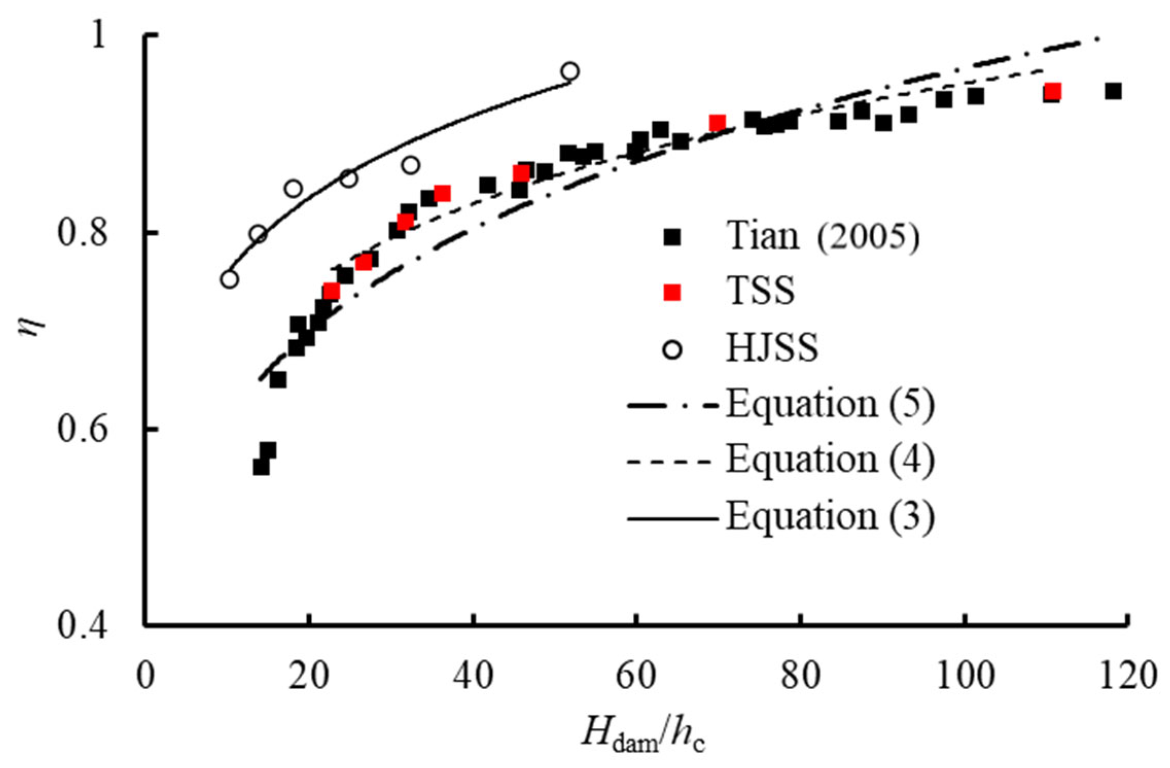
3.2. Energy Dissipation
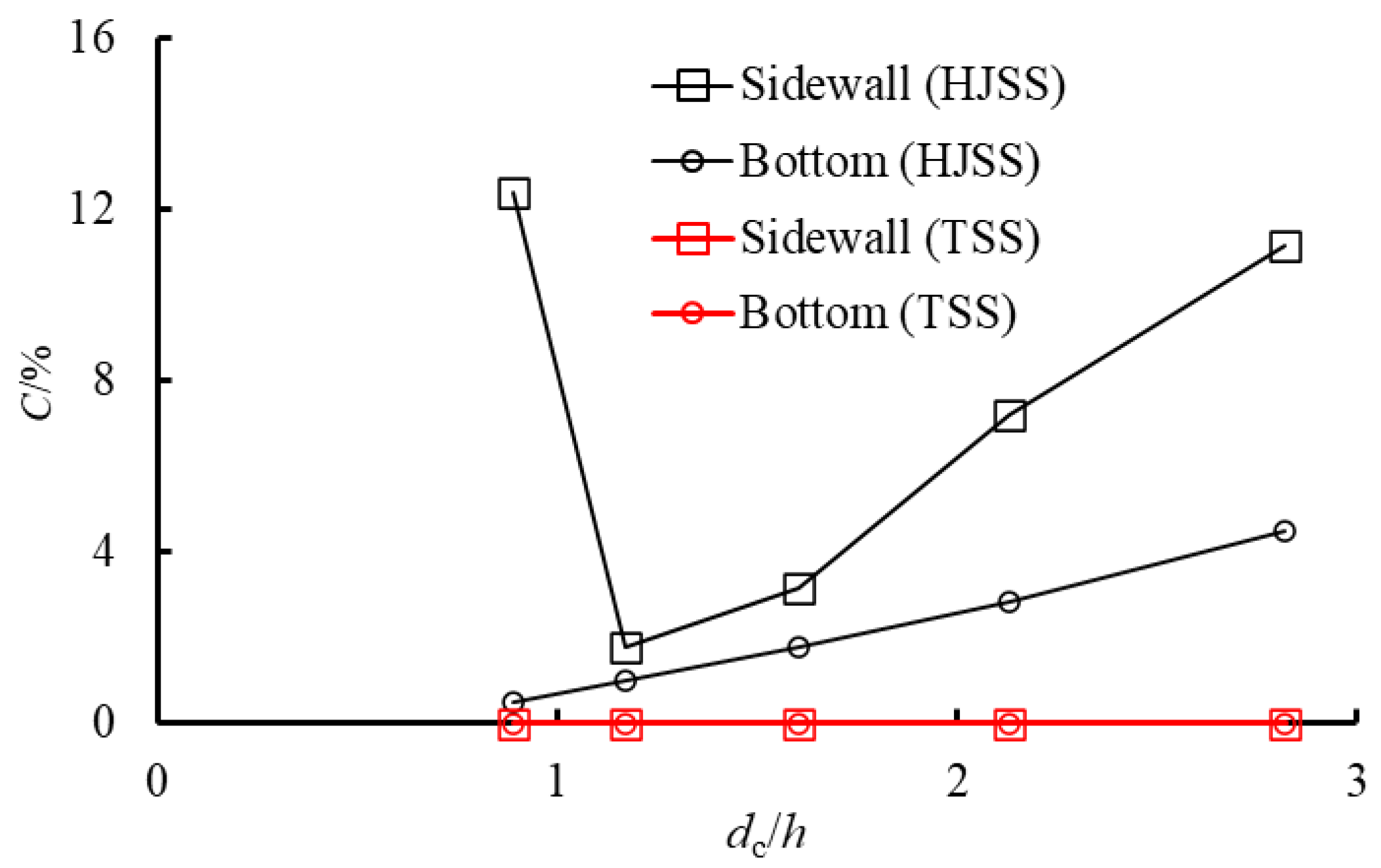
3.3. Pre-Aeration Effect
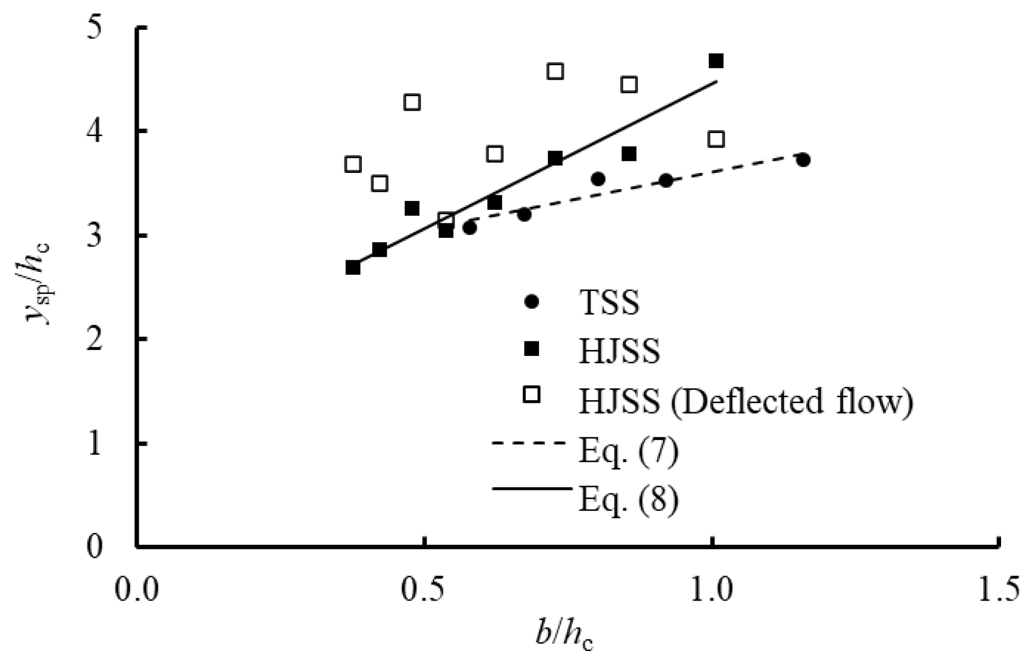
3.4. Maximum Splash Height
4. Conclusions
Author Contributions
Funding
Data Availability Statement
Conflicts of Interest
Nomenclature
| a | Step length |
| b | Step height |
| la | Length of the basin |
| ha | Height of the basin |
| B | Model width |
| q | Unit discharge |
| hc | Critical depth |
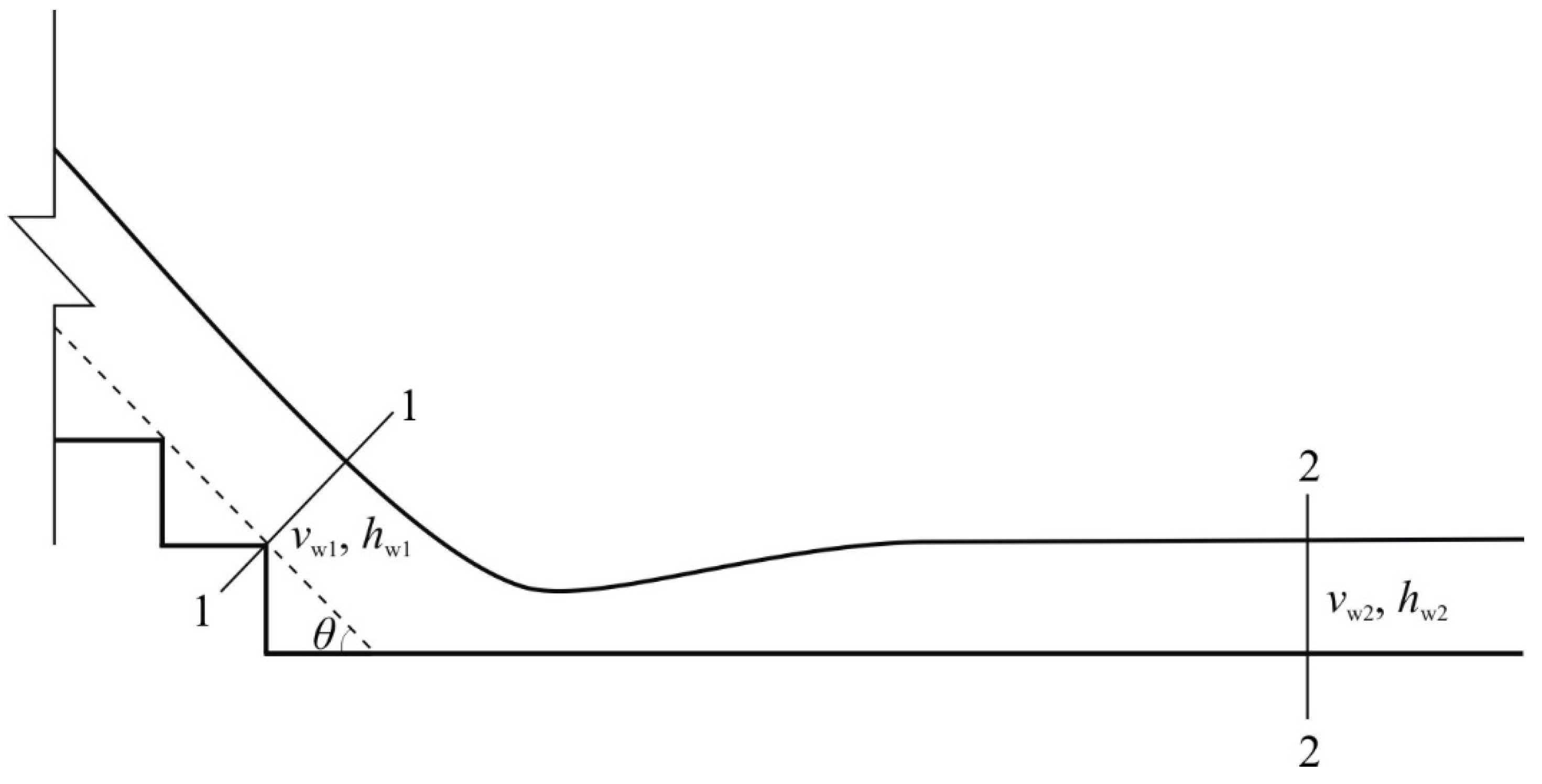
| hw1, hw2 | Equivalent clear water flow depth of calculated Section 1 and Section 2 |
| vw1, vw2 | Flow velocity of calculated Section 1 and Section 2 |
| hs | Reverse step height |
| Hdam | Total height from the weir crest to the outflow channel bottom |
| Hmax | Upstream total head above the outflow channel |
| Hres | Residual head at the last step edge |
| C | Air concentration |
| k | Roughness height perpendicular to the pseudobottom |
| F* | Roughness Froude number |
| ysp | Distance above the step edge to the observed splash line on the sidewall |
| Hi | Height between the first step and the inception point of air entrainment |
| Re | Reynolds number |
| α1, α2 | Kinetic energy correction coefficient |
| η | Energy dissipation rate |
| θ | Stepped spillway slope angle |
| g | Acceleration of gravity |
References
- Chanson, H. Energy dissipation on stepped spillways and hydraulic challenges—Prototype and laboratory experiences. J. Hydrodyn. 2022, 34, 52–62. [Google Scholar] [CrossRef]
- Chanson, H. Stepped Spillway Prototype Operation and Air Entrainment: Toward a Better Understanding of the Mechanisms Leading to Air Entrainment in Skimming Flows. J. Hydraul. Eng. 2022, 148, 05022004. [Google Scholar] [CrossRef]
- Zhou, Y.; Wu, J.; Zhao, H.; Hu, J.; Zhou, J.; Bai, F. Discussion of “Air–Water Flows and Head Losses on Stepped Spillways with Inclined Steps”. J. Irrig. Drain. Eng. 2023, 149, 07023010. [Google Scholar] [CrossRef]
- Zhou, Y.; Wu, J.H.; Qian, S.T.; Ding, C.M.; Pan, G.Y. Discussion of “Types I, II, III, and IV Stilling Basin Performance for Stepped Chutes Applied to Embankment Dams” by Sherry L. Hunt and Kem C. Kadavy. J. Hydraul. Eng. 2023, 149, 07022008. [Google Scholar] [CrossRef]
- Felder, S.; Chanson, H. Energy dissipation down a stepped spillway with nonuniform step heights. J. Hydraul. Eng. 2011, 137, 1543. [Google Scholar] [CrossRef]
- Qian, S.T.; Wu, J.H.; Xu, H.; Ma, F. Transition flow occurrence on stepped channels. J. Hydraul. Res. 2022, 60, 487–495. [Google Scholar] [CrossRef]
- Zare, H.K.; Doering, J.C. Effect of rounding edges of stepped spillways on the flow characteristics. Can. J. Civ. Eng. 2012, 39, 140–153. [Google Scholar] [CrossRef]
- Sánchez-juny, M.; Bladé, E.; Dolz, J. Pressures on a stepped spillway. J. Hydraul. Res. 2007, 45, 505–511. [Google Scholar] [CrossRef]
- Amador, A.; Sánchez-Juny, M.; Dolz, J. Characterization of the nonaerated flow region in a stepped spillway by PIV. J. Fluids Eng. 2006, 128, 1266–1273. [Google Scholar] [CrossRef]
- Matos, J.; Novakoski, C.K.; Ferla, R.; Marques, M.G.; Dai Prá, M.; Canellas, A.V.B.; Teixeira, E.D. Extreme Pressures and Risk of Cavitation in Steeply Sloping Stepped Spillways of Large Dams. Water 2022, 14, 306. [Google Scholar] [CrossRef]
- Pfister, M.; Hager, W.H.; Minor, H.-E. Stepped chutes: Pre-aeration and spray reduction. Int. J. Multiph. Flow 2006, 32, 269–284. [Google Scholar] [CrossRef]
- Chanson, H. Discussion of “Cavitation Potential of Flow on Stepped Spillways” by K. Warren Frizell, Floriana M. Renna, and Jorge Matos. J. Hydraul. Eng. 2015, 141, 07014025-1–07014025-2. [Google Scholar] [CrossRef]
- Li, S.; Zhang, J.M.; Xu, W.L. Numerical investigation of air–water flow properties over steep flat and pooled stepped spillways. J. Hydraul. Res. 2018, 56, 1–14. [Google Scholar] [CrossRef]
- Hunt, S.L.; Kadavy, K.C. Inception point for stepped chute designs with multiple sections of different step heights. J. Hydraul. Eng. 2021, 147, 06021001. [Google Scholar] [CrossRef]
- Arosquipa Nina, Y.; Shi, R.; Wüthrich, D.; Chanson, H. Air–Water Flows and Head Losses on Stepped Spillways with Inclined Steps. J. Irrig. Drain. Eng. 2022, 148, 04022037. [Google Scholar] [CrossRef]
- Li, S.; Yang, J.; Li, Q. Numerical modelling of air-water flows over a stepped spillway with chamfers and cavity blockages. KSCE J. Civ. Eng. 2020, 24, 99–109. [Google Scholar] [CrossRef]
- Li, S.; Yang, J.; Liu, W. Estimation of aerator air demand by an embedded multi-gene genetic programming. J. Hydroinformatics 2021, 23, 1000–1013. [Google Scholar] [CrossRef]
- Pfister, M.; Hager, W.H.; Minor, H.-E. Bottom aeration of stepped spillways. J. Hydraul. Eng. 2006, 132, 850–853. [Google Scholar] [CrossRef]
- Zamora, A.S.; Pfister, M.; Hager, W.H.; Minor, H.-E. Hydraulic performance of step aerator. J. Hydraul. Eng. 2008, 134, 127–134. [Google Scholar] [CrossRef]
- Chanson, H. Predicting the filling of ventilated cavities behind spillway aerators. J. Hydraul. Res. 1995, 33, 361–372. [Google Scholar] [CrossRef]
- Meireles, I.; Renna, F.; Matos, J.; Bombardelli, F. Skimming, nonaerated flow on stepped spillways over roller compacted concrete dams. J. Hydraul. Eng. 2012, 138, 870–877. [Google Scholar] [CrossRef]
- Tullis, B.P.; Jorgensen, T.J.; Crookston, B.M. Effects of a labyrinth weir with outlet ramps on downstream steep-stepped chute sidewall height requirements. J. Irrig. Drain. Eng. 2021, 147, 04021057. [Google Scholar] [CrossRef]
- Ma, F.; Wu, J.H. Hydraulics of abrupt contraction aerator on stepped chutes. J. Hydraul. Res. 2021, 59, 345–350. [Google Scholar] [CrossRef]
- Wu, J.H.; Qian, S.T.; Wang, Y.; Zhou, Y. Residual energy on ski-jump-step and stepped spillways with various step configurations. J. Hydraul. Eng. 2020, 146, 06020002. [Google Scholar] [CrossRef]
- Zhou, Y.; Wu, J.H.; Ma, F.; Qian, S.T. Experimental investigation of the hydraulic performance of a hydraulic-jump-stepped spillway. KSCE J. Civ. Eng. 2021, 25, 3758–3765. [Google Scholar] [CrossRef]
- Wu, J.H.; Zhou, Y.; Ma, F. Air entrainment of hydraulic jump aeration basin. J. Hydrodyn. 2018, 30, 962–965. [Google Scholar] [CrossRef]
- Zhou, Y.; Wu, J.H.; Ma, F.; Hu, J.Y. Uniform flow and energy dissipation of hydraulic-jump-stepped spillways. Water Supply 2020, 20, 1546–1553. [Google Scholar] [CrossRef]
- Zhou, Y.; Wu, J.H.; Ma, F.; Hu, J.Y.; Zhou, J.F. Jet flow in hydraulic-jump-stepped spillways: Experimental study. Water Supply 2022, 22, 4690–4699. [Google Scholar] [CrossRef]
- Chanson, H.; Brattberg, T. Experimental study of the air–water shear flow in a hydraulic jump. Int. J. Multiph. Flow 2000, 26, 583–607. [Google Scholar] [CrossRef]
- Wang, H.; Chanson, H. Experimental study of turbulent fluctuations in hydraulic jumps. J. Hydraul. Eng. 2015, 141, 04015010. [Google Scholar] [CrossRef]
- Han, Y.; Feng, R.L.; Tian, J.N.; Li, B.L. Water-wing on steep slope of stepped spillways. J. Hydroelectr. Eng. 2006, 25, 114–118. [Google Scholar] [CrossRef]
- Takahashi, M.; Ohtsu, I. Aerated flow characteristics of skimming flow over stepped chutes. J. Hydraul. Res. 2012, 50, 427–434. [Google Scholar] [CrossRef]
- Chinnarasri, C.; Wongwises, S. Flow patterns and energy dissipation over various stepped chutes. J. Irrig. Drain. Eng. 2006, 132, 70–76. [Google Scholar] [CrossRef]
- Arosquipa Nina, Y.; Shi, R.; Wüthrich, D.; Chanson, H. Aeration performances and air—Water mass transfer on steep stepped weirs with horizontal and inclined steps. J. Hydrodyn. 2022, 34, 904–916. [Google Scholar] [CrossRef]
- Qian, S.T.; Wu, J.H.; Ma, F. Hydraulic performance of ski-jump-step energy dissipater. J. Hydraul. Eng. 2016, 142, 05016004. [Google Scholar] [CrossRef]
- Shen, J.; Wu, J.; Ma, F. Hydraulic characteristics of stepped spillway dropshafts. Sci. China Technol. Sci. 2019, 62, 868–874. [Google Scholar] [CrossRef]
- Liu, J.; Ma, F.; Wu, J. Effects of Stepped Chute Slope and Slit Location on a Jet from Abrupt Contraction Aerator. J. Hydraul. Eng. 2024, 150, 06023011. [Google Scholar] [CrossRef]
- Hunt, S.L.; Kadavy, K.C. Estimated splash and training wall height requirements for stepped chutes applied to embankment dams. J. Hydraul. Eng. 2017, 143, 06017018. [Google Scholar] [CrossRef]
- Tian, J.N. Hydraulic Characteristics of Stepped Release Structure. Ph.D. Thesis, Xi’an University of Technology, Xi’an, China, 2005. [Google Scholar]
- Ohtsu, I.; Yasuda, Y.; Hashiba, H. Incipient jump conditions for flows over a vertical sill. J. Hydraul. Eng. 1996, 122, 465–469. [Google Scholar] [CrossRef]
- Felder, S.; Chanson, H. Aeration, flow instabilities, and residual energy on pooled stepped spillways of embankment dams. J. Irrig. Drain. Eng. 2013, 139, 880–887. [Google Scholar] [CrossRef]
- Felder, S.; Geuzaine, M.; Dewals, B.; Erpicum, S. Nappe flows on a stepped chute with prototype-scale steps height: Observations of flow patterns, air-water flow properties, energy dissipation and dissolved oxygen. J. Hydro-Environ. Res. 2019, 27, 1–19. [Google Scholar] [CrossRef]
- Boes, R.M.; Hager, W.H. Two-phase flow characteristics of stepped spillways. J. Hydraul. Eng. 2003, 129, 661–670. [Google Scholar] [CrossRef]
- Frizell, K.W.; Renna, F.M.; Matos, J. Cavitation potential of flow on stepped spillways. J. Hydraul. Eng. 2013, 139, 630–636. [Google Scholar] [CrossRef]
- Zare, H.K.; Doering, J.C. Inception point of air entrainment and training wall characteristics of baffles and sills on stepped spillways. J. Hydraul. Eng. 2012, 138, 1119–1124. [Google Scholar] [CrossRef]
- Wang, H.; Bai, Z.T.; Liu, X.C.; Bai, R.D.; Liu, S.J. Flow aeration and surface fluctuations in moderate-slope stepped chute: From aeration inception to fully developed aerated flow. J. Hydraul. Res. 2022, 60, 944–958. [Google Scholar] [CrossRef]

| Equation | R2 | MSE | RMSE | MAE |
|---|---|---|---|---|
| Equation (3) | 0.94 | 0.0003 | 0.0002 | 0.0250 |
| Equation (4) | 0.95 | 0.0157 | 0.0129 | 0.1259 |
| Equation (5) | 0.90 | 0.0170 | 0.0147 | 0.1580 |
Disclaimer/Publisher’s Note: The statements, opinions and data contained in all publications are solely those of the individual author(s) and contributor(s) and not of MDPI and/or the editor(s). MDPI and/or the editor(s) disclaim responsibility for any injury to people or property resulting from any ideas, methods, instructions or products referred to in the content. |
© 2024 by the authors. Licensee MDPI, Basel, Switzerland. This article is an open access article distributed under the terms and conditions of the Creative Commons Attribution (CC BY) license (https://creativecommons.org/licenses/by/4.0/).
Share and Cite
Zhou, Y.; Xin, F.; Xu, K.; Mei, J.; Jia, S.; Qiu, H.; Wang, Y. A New Type of Pre-Aeration Stepped Spillway. Water 2024, 16, 3213. https://doi.org/10.3390/w16223213
Zhou Y, Xin F, Xu K, Mei J, Jia S, Qiu H, Wang Y. A New Type of Pre-Aeration Stepped Spillway. Water. 2024; 16(22):3213. https://doi.org/10.3390/w16223213
Chicago/Turabian StyleZhou, Yu, Fangyong Xin, Ke Xu, Jiakai Mei, Siwei Jia, Haodong Qiu, and Yuanyuan Wang. 2024. "A New Type of Pre-Aeration Stepped Spillway" Water 16, no. 22: 3213. https://doi.org/10.3390/w16223213
APA StyleZhou, Y., Xin, F., Xu, K., Mei, J., Jia, S., Qiu, H., & Wang, Y. (2024). A New Type of Pre-Aeration Stepped Spillway. Water, 16(22), 3213. https://doi.org/10.3390/w16223213