Abstract
Rainfall infiltration is the primary triggering factor for the instability of unsaturated slopes. At present, rainfall-induced landslides are mainly considered to be influenced by the overall infiltration conditions, while few investigations have been conducted on the influence of infiltration boundaries on slope instability. This study proposes a rainfall infiltration method using a discrete element model (DEM), which is based on saturated–unsaturated seepage theory. The influence of three infiltration boundaries on the instability of homogeneous unsaturated soil slopes was studied. The results showed that the infiltration rate of a rainfall-covered slope crest was faster than that of rainfall-covered slope surfaces. A transient saturated zone was formed on the slope surface after a certain duration of rainfall. Rain infiltration boundary conditions significantly impact the saturation distribution, seepage field, failure mode, and failure period. The safety and stability factors for the rainfall-covered slope crest and full area decreased monotonically with the increase in rainfall duration, while there was a brief increase at the initial stage of rainfall before a quick decline for rainfall-covered slope surfaces. This research provides a preliminary exploration of the impact of rainfall boundary conditions on the instability of slopes, offering a reference basis for DEM simulations that consider slope stability under the influence of rainfall infiltration.
1. Introduction
Rainfall infiltration is a key triggering factor for slope instability [1]. Engineering experiences indicate that rainfall infiltration alters the hydraulic head distribution within slopes. This process affects matric suction, moisture content, and the permeability coefficient over time [2]. It also raises groundwater levels, reduces soil shear strength [3], and impacts slope stability, potentially leading to failure [4]. Researchers conduct indoor and field monitoring experiments to track changes in moisture content and water pressure. These observations help infer the occurrence and development patterns of landslides [5,6,7]. However, the restricted number of monitoring points makes it difficult to fully capture the development patterns of water migration, matric suction, and effective stress within a slope. Thus, numerical simulation methods are used as supplementary approaches to investigate rainfall-induced slopes [8,9,10,11].
Recently, DEMs have been used to study slopes’ instability and accumulation properties. They effectively capture interactions and deformation characteristics among particles [12]. Rainfall infiltration simulations based on DEMs are primarily accomplished by simplifying the rainfall processes and coupling them with fluid calculation methods. Simplifying the rainfall process often results in the unsaturated–saturated seepage process being neglected. Instead, saturated soil parameters are used, seepage forces are applied, and the friction coefficient is reduced to model rainfall infiltration effects [13]. These methods fail to capture the variation patterns of a slope’s water content and material strength during rainfall.
When integrating fluid computation methods with discrete element software, CFD–DEM coupling [14,15] or PFC–FLAC coupling [16] is typically employed. The CFD–DEM coupling method generally establishes a fluid mesh within the model domain and calculates the interaction forces between fluid particles by solving the fluid equations [17,18,19]. PFC–FLAC coupling involves initially computing the internal seepage field of the model using FLAC software (version 3.0) and subsequently importing the computed seepage forces into the PFC software (version 3.1) [20]. Such methods add complexity to implementing rainfall infiltration processes in discrete elements, which typically makes it challenging to simulate flow fields in regions with complex shapes [21], thereby limiting their application in large-scale complex engineering studies. This shows that the key to simulating rainfall infiltration processes is the way of computing the patterns of water migration during infiltration and the effects on the soil. Selecting an appropriate simulation method that aligns with the research goals is essential.
Researchers study the moisture transport patterns and slope stability caused by rainfall by incorporating a rainfall infiltration model into a DEM. Geng et al. [22] utilized MatDEM to compare the rainwater infiltration depth and stability of the tailings of dam slopes in rainy and non-rainy seasons, and they predicted the extent of landslide failure for different seasons. Gu et al. [23] determined the moisture content of soil particles at the rainfall infiltration boundary based on the relationship between rainfall intensity and the soil permeability coefficient. The water diffusion, strength attenuation, and seepage force due to rainfall infiltration were considered. This method emphasized the selection of soil particles in contact with rainwater on the slope surface. Song et al. [24] investigated the stability of a slope during rainfall using models of cohesive strength degradation and viscous force, and they explored the seepage failure mechanisms caused by rainfall at soil–rock contact interfaces. Hung et al. [16] incorporated seepage force into a DEM and reduced the friction coefficient to study landslide movement behaviors triggered by rainfall. Overall, studies on the characteristics of the spatiotemporal evolution of internal slope failure development during rainfall and the influence of seepage force on the stability and safety factors of slopes are relatively scarce.
Additionally, most current studies on rainfall-induced landslides focus on full-area infiltration scenarios. However, real slope engineering involves numerous complex infiltration scenarios. Rainfall primarily enters embankment slopes through the slope surface, while structures such as retaining walls and excavation pits mainly facilitate the infiltration of moisture into the soil from the extended slope top; such a scenario is identified as that of a rainfall-covered slope crest. Additionally, factors such as water storage [25] and tunnel construction [26] cause fluctuations in the groundwater level, leading to seepage [27]. If slope instability occurs, it may result in considerable losses. Bao et al. [28] found through model experiments that top-slope infiltration, side infiltration, and bottom infiltration significantly affect the failure modes of embankment slopes. Song et al. [29] studied the impact of infiltration boundaries on slope deformation and failure using highly permeable standard sand. Their research indicates that the rainfall infiltration boundary alters the flow path of rainwater, thereby affecting the evolution of slope stability. Therefore, it is essential to study the effects of various rainfall infiltration boundary conditions on slope instability.
Based on the V g model, this study solves the Richards seepage equation to obtain the analytical solution for rainfall infiltration. This analytical solution is integrated with a DEM to investigate the saturation distribution and seepage field inside slopes under different rainfall infiltration boundary conditions. Additionally, this method is utilized to study the failure of slope instability under various infiltration boundary conditions.
2. Methods
2.1. Saturated–Unsaturated Seepage Model
The migration of water within a slope under rainfall infiltration conditions can be described by Darcy’s law, and this is categorized as the saturated–unsaturated seepage problem. According to the mass conservation principle and Darcy’s law, the Richards equation [30] for describing saturated–unsaturated seepage is expressed as follows:
where θ represents the volumetric water content; k(θ) is the hydraulic conductivity at a given water content, with subscripts x and y denoting the hydraulic conductivity in the corresponding directions; h is the total hydraulic head; and C(θ) is the capillary capacity, which refers to the change in water content in the soil caused by pressure changes.
Solving the Richards equation provides the spatiotemporal relationships of parameters such as the water content, permeability coefficient, and matric suction.
The seepage equation is solved using the following boundary conditions:
where S1 denotes the known head boundary and S2 denotes the known flow boundary.
The initial conditions for the unsteady seepage analysis are the following:
where Ω indicates the seepage calculation area.
k(θ) and C(θ) must first be determined to solve this differential equation. As the volumetric water content in the soil decreases, the proportion of air in the pores increases, reducing the water flow area, thereby decreasing the hydraulic conductivity. Hence, the permeability coefficient of unsaturated soil is variable and functions as a factor of the soil’s volumetric water content.
The V-G model [31] derived from the Mualem capillary model [32] is widely used to predict the relationships between soil saturation, the pressure head, and the permeability coefficient. The expression is given as follows:
where Se denotes the relative saturation and n is an empirical coefficient associated with soil characteristics, with n > 1, m = 1 − 1/n. α is an empirical coefficient, Φ represents the negative pressure head, θr is the residual volumetric water content, θs is the saturated volumetric water content, and ks is the saturated permeability coefficient.
Solving the Richards equation with the given boundary conditions allows for obtaining the spatiotemporal characteristics of the seepage field during rainfall. The validity of the saturated–unsaturated seepage model has been confirmed by Vauclin et al. [33].
2.2. The Computational Model Considering the Impact of Rainfall Infiltration
The infiltration of rainfall into soil primarily affects the soil’s density and strength [34]. Rainfall infiltration increases the soil moisture content, resulting in an increase in soil bulk density. The soil bulk density can be determined using the following formula based on the soil’s volumetric water content:
where γ is the weight of soil when the moisture content is θ. γd is the dry weight of the soil, and γw is the water weight.
The influence of water on soil strength is mainly manifested in two aspects: one is that water has a softening effect on the soil [35], and the other is that an increase in soil water content will cause a decrease in matric suction, thereby reducing the shear strength of the soil [36]. In other words, the shear strength of soil has a significant correlation with its water content [37]. Based on the unsaturated soil strength formula, the relationship between the strength parameters and the relative saturation in the DEM was given as follows:
where θi represents the water content of the soil element at a given state, Si indicates the friction coefficient, normal bond strength, or tangential bond strength when the water content is θi, and S0 is the friction coefficient, normal bond strength, or tangential bond strength in the natural state.
Lo et al. [38] reduced the bond strength and friction coefficient to 52% of the dry state to simulate the effect of water on soil strength reduction. Shi et al. [25] summarized the mechanical parameters of soils from eight landslide cases in the saturated and natural states, finding that water saturation caused a 10–20% reduction in the soil mechanical parameters. This study assumes that the particle friction coefficient and bond strength of saturated soil are reduced to 85% of their natural state.
Furthermore, the movement of water induces a seepage force aligned with the direction of seepage flow in saturated soil. The equivalent seepage force [39] can be calculated as follows:
where V represents the volume of the particles and i denotes the hydraulic gradient, which is defined as the ratio of the head difference between two points to the distance of seepage.
2.3. Simulation Scheme for Rainfall Infiltration
When the rainfall intensity is less than the soil’s permeability coefficient, it can be assumed that all rainwater infiltrates into the slope and that surface runoff can be disregarded. During the rainfall process, the rain intensity remains unchanged until the slope becomes unstable.
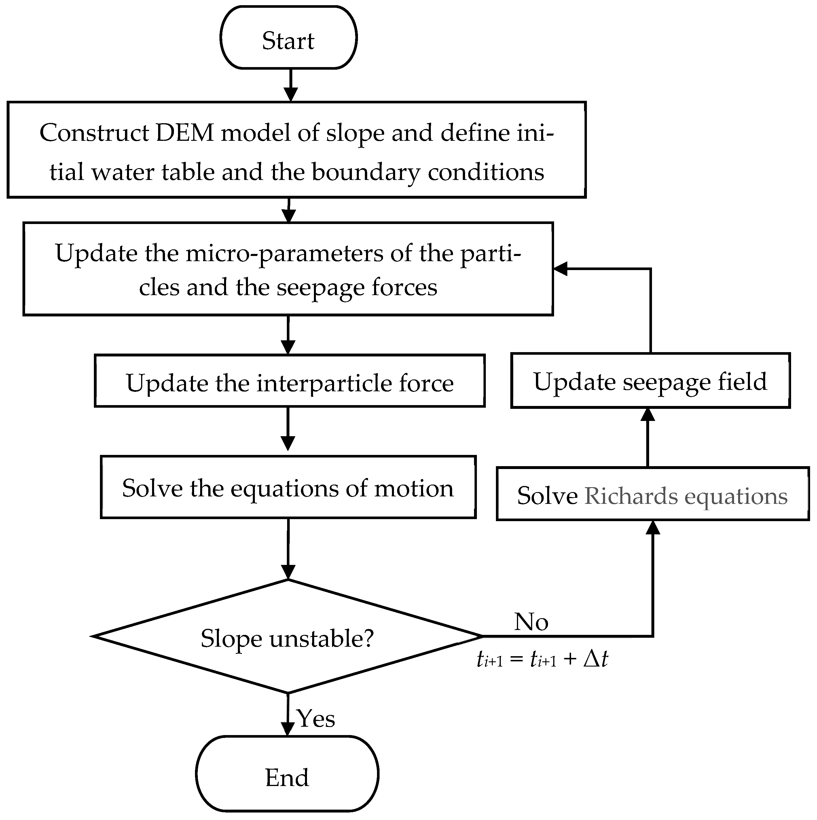
Figure 1 illustrates the analytical process for simulating rainfall infiltration using a DEM. First, a DEM of the slope is generated. The water table and seepage boundary conditions are set according to the initial conditions. Based on the initial water content and pressure head, linear interpolation is employed with each particle’s positional coordinates to compute the water content and pressure head corresponding to it. Subsequently, each particle’s micro-parameters and seepage force are determined. The calculation of the interaction forces areconducted until the slope model achieves a state of equilibrium. Then, the Richards seepage equation at time t1 = t0 + Δt is solved to obtain the pressure head, saturation, moisture content, and seepage field. The time step Δt used to solve the Richards equation is 0.002 h. Based on the moisture content, saturation, and seepage field, the micro-parameters and seepage force are updated. Iteratively, the motion equations are solved and the interparticle contact forces are updated in the DEM. All particle parameters and crack propagation within the slope model are monitored.
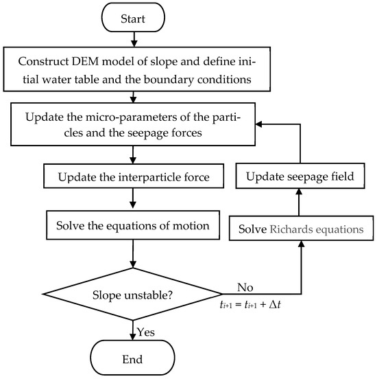
Figure 1.
Flowchart of the analysis of seepage behavior with the DEM.
If the slope remains stable, the seepage equation for the next time increment t2 = t1 + Δt is solved. The slope is considered stable if the internal crack propagation stops and the ratio of the maximum unbalanced force to the average unbalanced force reaches 1.0 × 10⁻⁵. The micro-parameters and seepage force in the DEM are updated and the slope’s stability at that moment is assessed. If the slope becomes unstable, the calculation is terminated.
3. Numerical Model and Mesoscopic Parameters of Slopes
3.1. Generation of a Slope Model
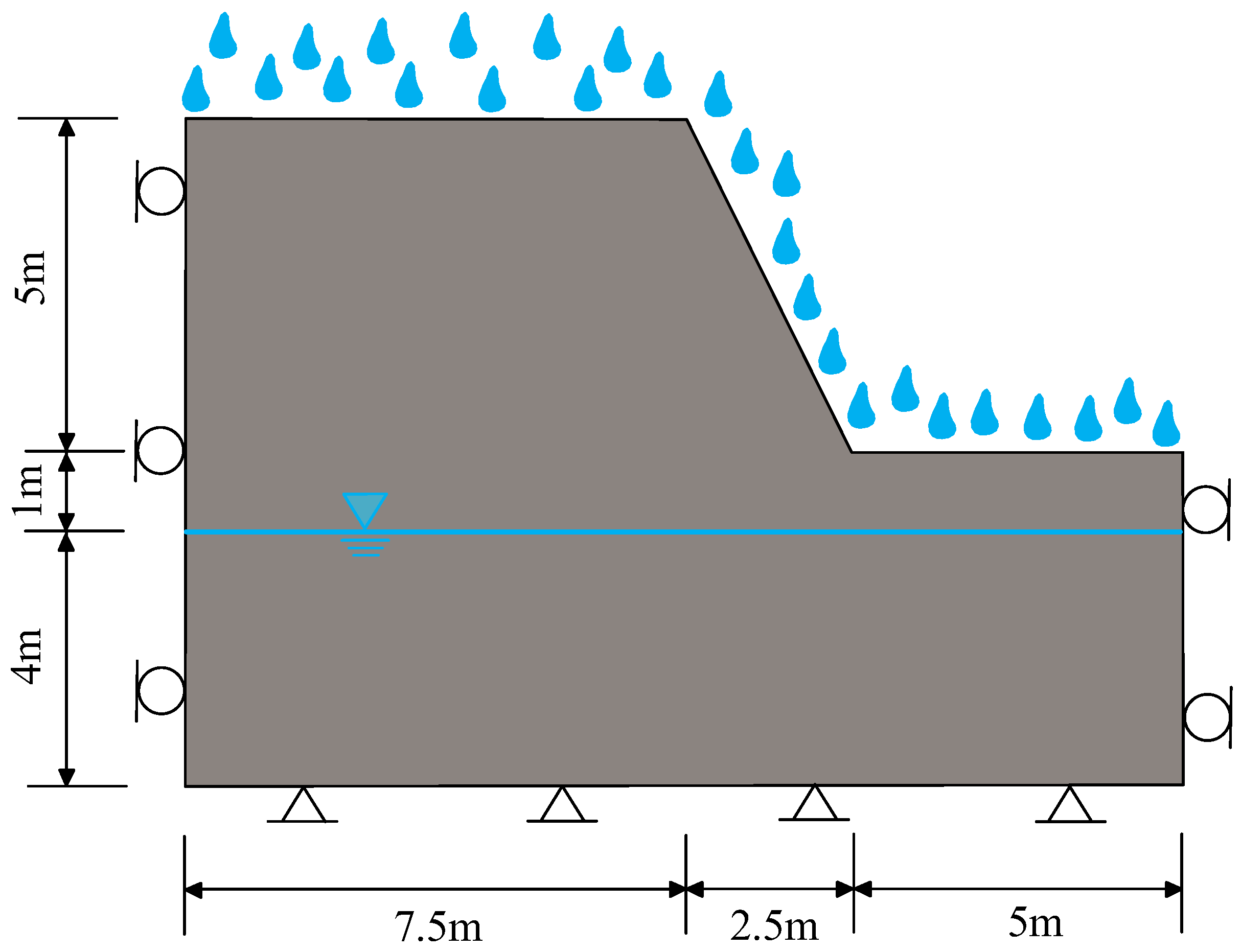
In recent years, the frequency of extreme rainfall events has increased in the mountainous regions of eastern Liaoning, China, leading to numerous small-scale landslides. These slopes are relatively low in height, with rainfall-induced landslides predominantly occurring in the shallow surface layers. To investigate the impact of rainfall infiltration boundaries, a slope was generated, as shown in Figure 2. The slope has a height of 5.0 m, with an inclination of 63.43° (1H:2V) with respect to the horizontal. The initial groundwater level is 4.0 m from the base of the slope. The natural moisture content of the soil above the water table is 21.13%.
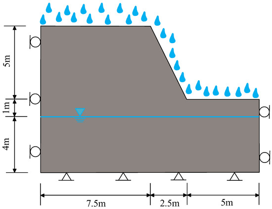
Figure 2.
The geometry and boundary conditions of a simple slope.
The boundary conditions are set as depicted in Figure 2. The bottom of the model prohibits horizontal and vertical displacements and is set as an impermeable boundary. The side boundaries prohibit horizontal displacement and are set as zero-flow boundaries.
The slope model was generated using a slope-cutting method. PFC2D (V5.0) was employed for the DEM. The number of particles is related to the computational stability and efficiency of the model. When the particle count meets certain requirements, the mechanical properties of the numerical model become independent of the particle size [40]. According to Sun et al. [41], the effect of size on computational models can be eliminated when the ratio of the model’s characteristic size to the particle size is at least 50.
Initially, an assembly of particles with sizes uniformly distributed from 15 to 30 cm was generated within a 15 m × 10 m rectangular area. The porosity of the particle assembly was set to 0.15. Next, the contact forces between particles were calculated incrementally. The model achieved equilibrium under self-weight conditions. After the model reached equilibrium, a parallel-bond model was applied. The final slope model with 61,641 balls was obtained through 40 slope cuts, as shown in Figure 3.
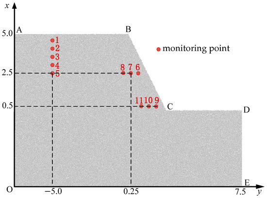
Figure 3.
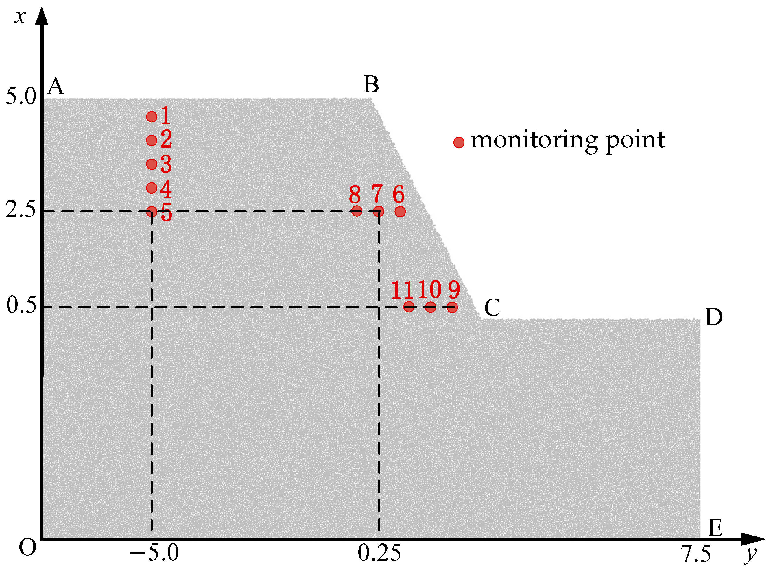
The balls in the DEM models and monitoring points.
To analyze the process of water infiltration, 11 monitoring points were set up, and the coordinates of the monitoring points are listed in Table 1. The specified rainfall intensity is 0.018 m/h. To account for the influence of rainfall infiltration boundaries on slope failure, three conditions are considered: a rainfall-covered slope crest (AB), a rainfall-covered slope surface (BC), and a full rainfall-covered slope area (AB-BC-CD).

Table 1.
Monitoring point coordinates.
3.2. Determination of the Soil Parameters
In DEM simulations, factors such as the particle shape, size, and compaction level influence the macroscopic mechanical characteristics. Therefore, mesoscopic parameters do not directly correspond to the macroscopic parameters of a material, and they are typically determined through a trial-and-error approach [42,43].
Rectangular biaxial samples were generated according to the particle size range in the slope model. Biaxial tests were conducted under confining pressures of 50 kPa, 100 kPa, and 150 kPa to determine the shear properties of the soil. The simulated stress–strain curves are shown in Figure 4 and the mesoscopic parameters used are listed in Table 2. The corresponding cohesion is 17.3 kPa and the friction angle is 23.3°.
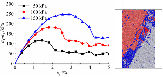
Figure 4.
The stress–strain curves of soil under different confining pressures.
Table 2.
Soil parameters.
The parameters related to rainfall infiltration, including saturated water content, residual water content, and saturated hydraulic conductivity, are based on previous research findings [44]. All soil properties are summarized in Table 2.
4. DEM Simulation Results
The process of the instability of soil slopes under different infiltration conditions was simulated. Landslide failure occurs in the slope after 12.4 h of continuous rainfall under full-area infiltration conditions. The failure time of the slope for the rainfall-covered slope crest is 37 h, and, under slope surface infiltration conditions, the failure time is 16.6 h. The slope failure timing was largely consistent with the experimental results of Song et al. [29]. For full-area infiltration, the rainwater infiltration range was the largest, causing the slope to fail first. In the case of slope top infiltration, the slope required the longest rainfall duration to fail and rainwater did not reach the slope toe. The slope data at the moment of failure were saved, and the saturation and crack propagation data within the soil during rainfall were recorded.
4.1. Distribution of Saturation and the Seepage Field
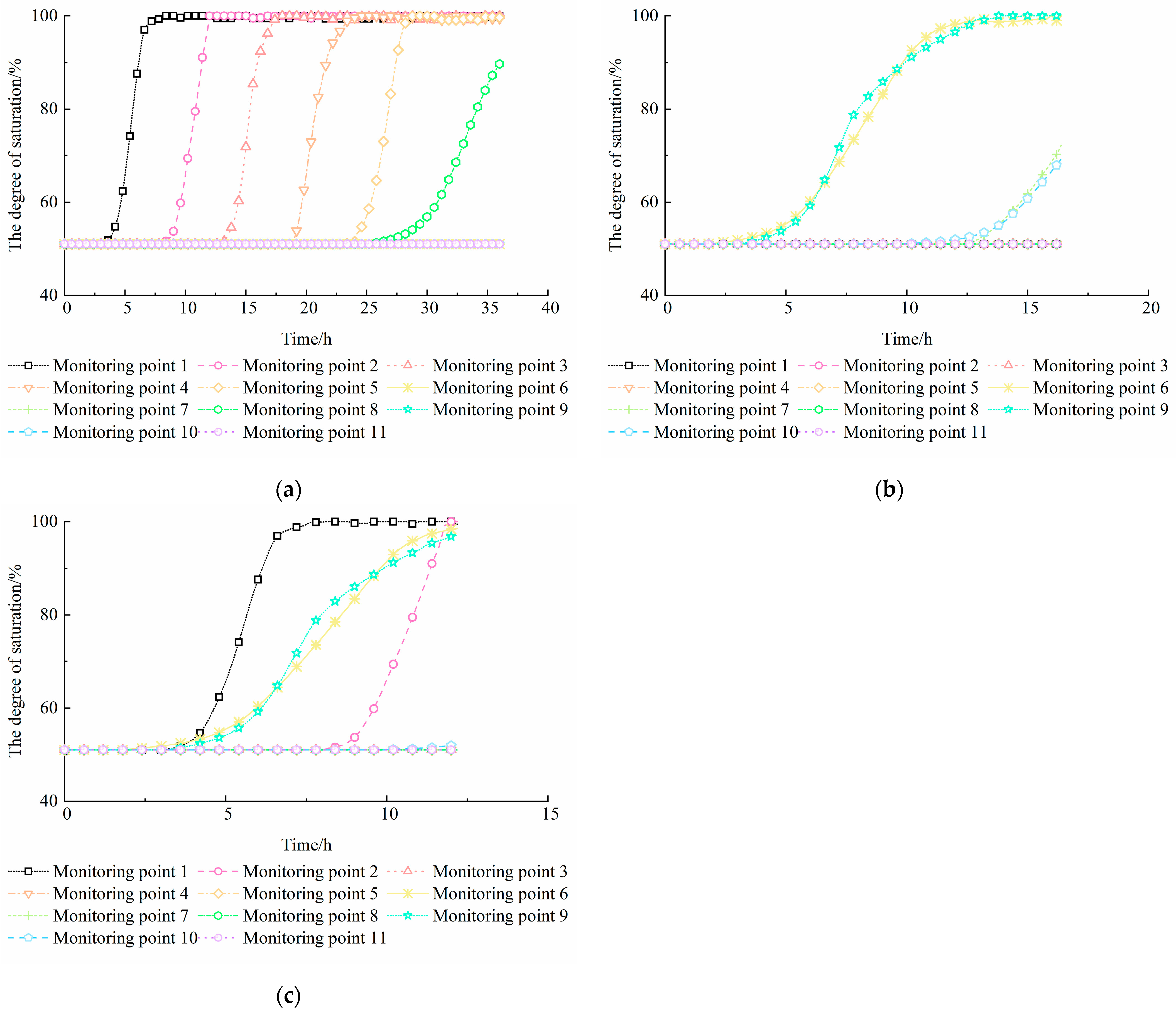
Figure 5 shows the distribution of the soil saturation degree at the monitoring points of the slope during rainfall. It indicates that different rainfall infiltration boundaries significantly affect the internal moisture distribution within the slope. As shown in Figure 5a, monitoring point 1 reached a saturation of 100% at 8.2 h when infiltration occurred at the slope crest. As the rainfall continued, monitoring points 2, 3, 4, and 5 sequentially reached a saturation of 100%. This indicated that the 3.5 m-thick soil layer beneath the slope top reached saturation. The saturation of monitoring points 6 and 7 near the slope surface remained almost unchanged, indicating that no water penetrated points 6 and 7 during the rainfall. The rate of increase in the saturation at monitoring point 8 was relatively slow. The primary cause was that water infiltrated the slope from the top, initially reaching monitoring point 8, which was located farther from the slope surface. No water infiltrated monitoring points 7 and 6, which were closer to the slope surface, and the saturation at monitoring points 9, 10, and 11 near the slope toe showed no change, confirming that no water entered the slope toe. This observation aligned closely with the results of the modeling experiment reported by Bao et al. [28].
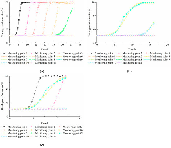
Figure 5.
The variation in the degree of saturation during the rainfall process at different monitoring points: (a) rainfall-covered slope crest; (b) rainfall-covered slope surface; (c) full rainfall-covered slope area.
Figure 5b shows the variation in saturation at different monitoring points under conditions of slope surface infiltration. It indicates that only monitoring points 6, 7, 9, and 10 near the slope surface had water ingress. Monitoring point 6 reached 100% saturation at 16 h. Monitoring points 6 and 9 eventually reached saturation, indicating that a transient saturated zone developed near the slope surface after sustained rainfall.
Figure 5c illustrates the saturation changes at different monitoring points under conditions of full-area infiltration. According to Figure 5c, monitoring point 1 reached saturation first, with monitoring point 2 reaching saturation before slope failure. At 12.2 h, monitoring points 6 and 9 achieved saturation degrees of 98.6% and 97.2%, respectively. This indicated that rainwater infiltrated into the soil from the slope face at a slower rate than from the crest of the slope. Water did not enter at monitoring points 3, 4, 5, 7, 8, 10, and 11. This indicated that rainwater did not infiltrate into the slope body, and a transient saturated zone with a thickness of approximately 0.5–1 m was formed on the slope surface. Thus, it was evident that rainfall infiltration boundaries directly influenced the moisture distribution within the slope, which was the fundamental cause affecting the evolution of slope stability.
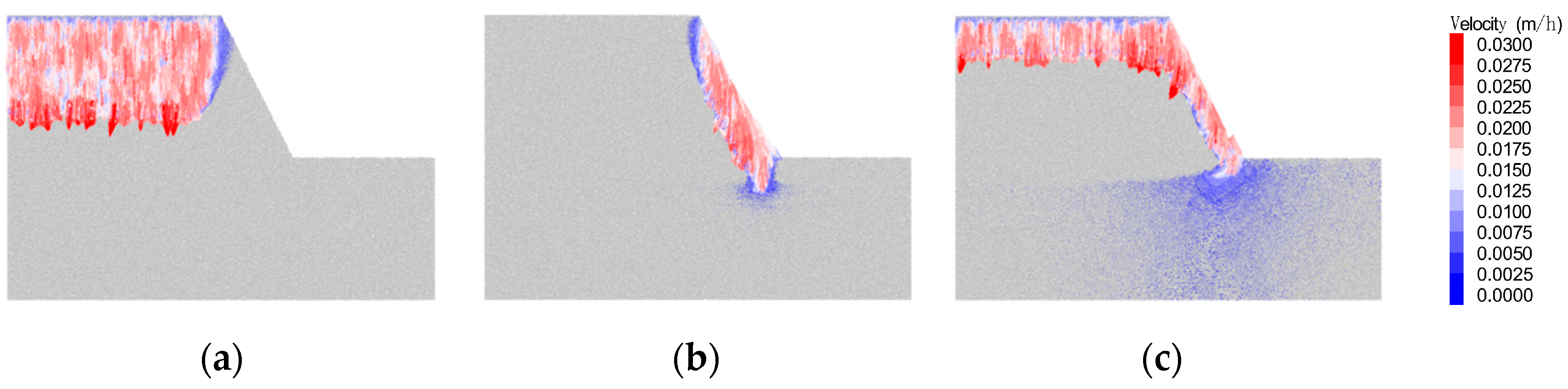
The seepage velocity and the distribution during rainfall infiltration directly reveal the infiltration behavior and the seepage force distribution within a slope. Figure 6 depicts the distribution of the seepage velocity vector in the slope as it approaches failure.
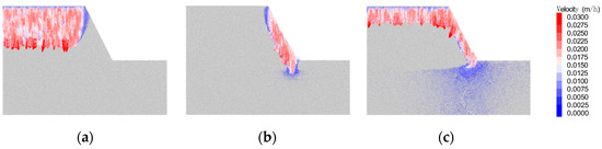
Figure 6.
Vector field of the seepage velocity of the slope in different rainfall infiltration scenarios: (a) rainfall-covered slope crest; (b) rainfall-covered slope surface; (c) full rainfall-covered slope area.
It is evident that, under crest infiltration conditions, rainwater primarily seeps downward, with slower infiltration rates near the slope surface. Under surface infiltration conditions, gravity causes water to primarily move downward along the slope, creating a component of water flow within the slope perpendicular to the slope surface. Under the combined influence of gravity and the hydraulic head difference, water primarily flows toward the interior of the slope and the slope toe. The soil within the slope is in an unsaturated state with a low pressure head, causing water to flow toward areas with a lower head, resulting in a vertical component of flow toward the slope surface. Under full-area infiltration conditions, the seepage velocity of rainwater on the slope surface is slower than that at the top of the slope.
4.2. Influence of the Infiltration Boundary on the Failure Mode of the Slope
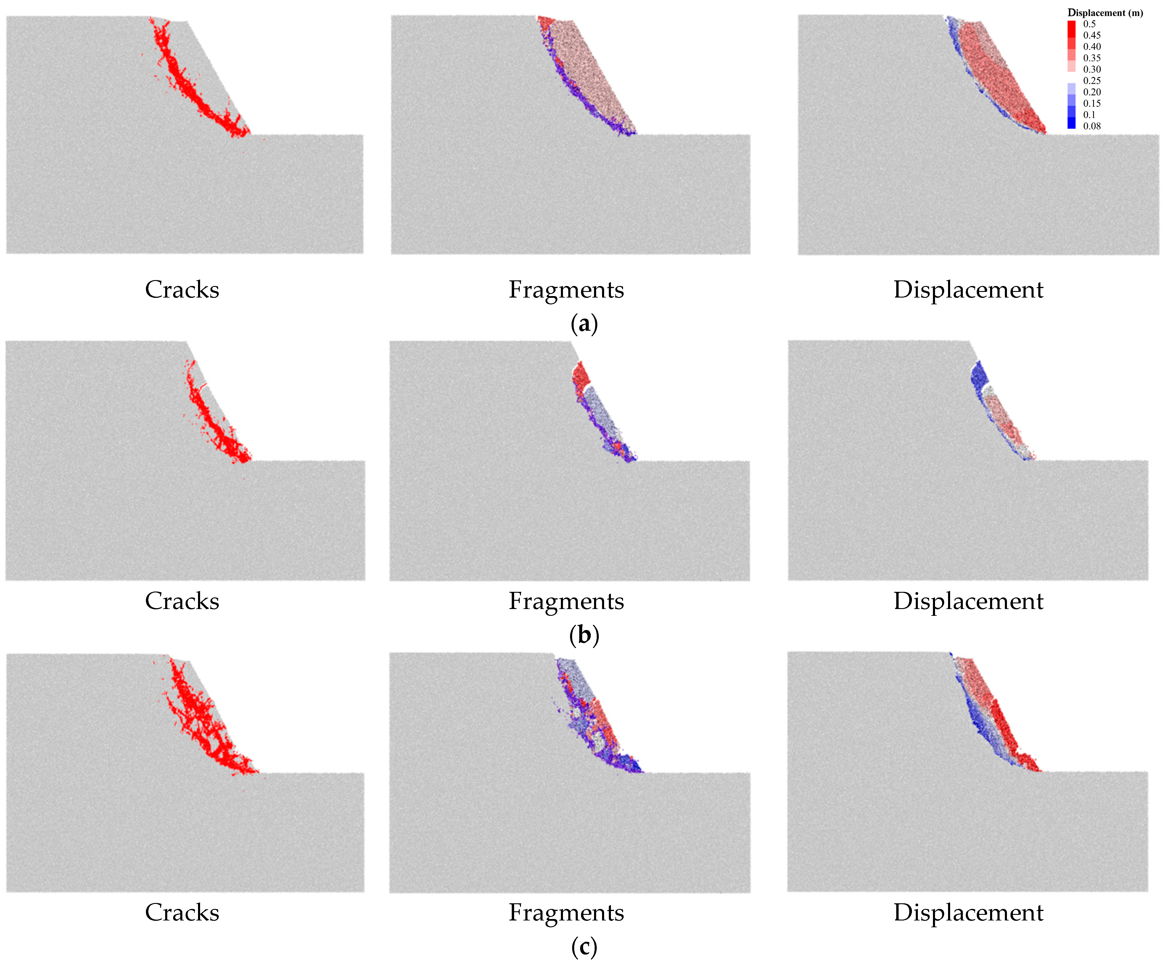
To investigate the impact of rainfall infiltration boundaries on slope failure patterns, the distribution of cracks within the slope, landslide debris, and displacement conditions during slope failure were compiled, as shown in Figure 7. Figure 7 shows the distribution of cracks, debris, and displacement in the context of slope failure under different infiltration boundary conditions. The cracks are mainly distributed along an arc-shaped sliding surface under the rainfall-covered slope crest conditions, as shown in Figure 7a. The sliding mass is relatively intact, exhibiting a wide top and narrow bottom. The sliding mass has the largest volume, and the landslide body remains fairly intact, sliding downward as a whole.
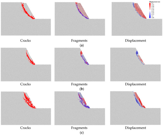
Figure 7.
Crack distribution, landslide debris, and slope displacement during slope failure: (a) rainfall-covered slope crest; (b) rainfall-covered slope surface; (c) full rainfall-covered slope area.
Figure 7b shows that the cracks are near the slope surface under conditions of slope surface infiltration. The sliding surface does not extend to the crest of the slope. This forms a sliding block with a narrow top and bottom but a wide middle. In this situation, the sliding soil mass has the smallest volume, with larger displacement in blocks near the slope toe.
Figure 7c shows that two main cracks form inside the slope body under full-area infiltration conditions. The slope toe fails first, followed by cracks near the slope surface extending to the slope crest, leading to slope instability in a traction-like manner. This manifests as a traction-type landslide failure. The sliding block experiences severe internal fragmentation, and the displacement of blocks near the slope surface is more pronounced.
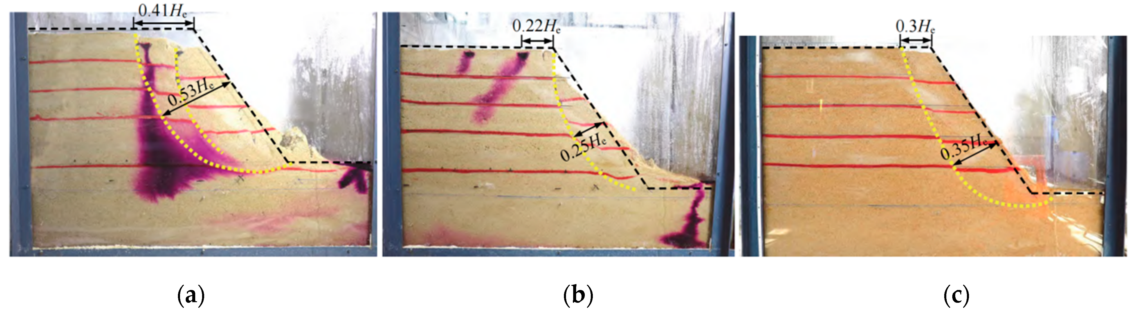
These results are consistent with the results of a model experiment on sandy slopes (Figure 8) conducted by Song et al. [29], which indicates that the rainfall infiltration boundary significantly influences the slope failure mode.
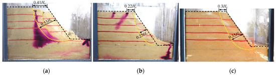
Figure 8.
Failure pattern obtained from the model test of a homogeneous sandy slope in [29]: (a) rainfall-covered slope crest; (b) rainfall-covered slope surface; (c) full rainfall-covered slope area.
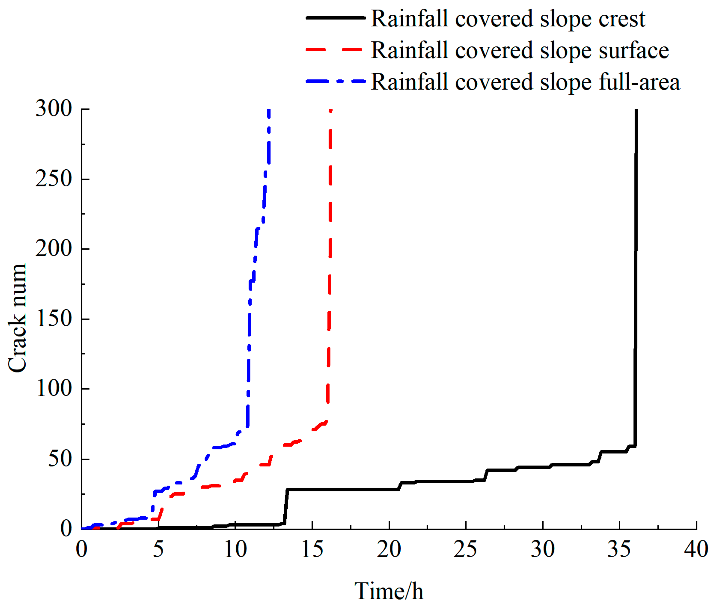
The evolution of the crack number during rainfall is depicted in Figure 9. It shows that the crack propagation patterns in the slope body are similar. Initially, cracks develop slowly. However, once the threshold of slope failure is reached, the number of cracks rapidly increases, ultimately resulting in complete slope failure. Under rainfall-covered slope crest conditions, the first crack appears at the slope toe after 5 h of rainfall, and the cracks suddenly enlarge at 36.8 h. As explained in Section 4.1, the water does not infiltrate the slope toe during failure, leaving the soil strength unchanged due to the absence of rainfall infiltration. It can be inferred that the main reason for failure is that rainfall infiltration increases the soil’s unit weight and downward seepage forces, thereby enhancing the sliding force. For the rainfall-covered slope surface, a significant increase in cracks occurs at 16.2 h, followed by rapid crack growth, leading to slope surface failure at 16.6 h. Rainwater infiltrates the failure surface, and the weakening of soil strength, seepage, and increased soil unit weight caused by the water leads to soil failure. At 0.4 h, cracks appear at the slope toe under full-area infiltration conditions. A significant mutation occurs at 11 h, and, by 12.4 h, the cracks grow continuously until complete penetration and slope failure. Comprehensive slope infiltration includes two working conditions that negatively impact slope stability, crest infiltration and slope surface infiltration, which accelerate the slope’s failure process.
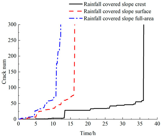
Figure 9.
Evolution law of crack numbers in different rainfall infiltration scenarios.
4.3. The Impact of Infiltration Boundaries on Safety Factors
The stability and safety factors of slopes during rainfall are determined using the strength reduction method [45]. Zhou et al. [46] introduced the strength reduction method into a DEM, and they assumed that the friction coefficient and bonding strength share the same safety reserve. The bonding strength and friction coefficient are reduced with the reduction coefficient [47].When the slope reaches its limit equilibrium state, the associated reduction coefficient is defined as the factor of safety (Fos = μ/μr = τc/τcr = σc/σcr). Here, μr, τcr, and σcr correspond to the friction coefficient, shear strength, and normal bonding strength in the critical state of the slope. The factor of safety is determined using the bisection method. It is terminated when the difference between two consecutive safety factors is less than 0.001.
The evolution of the slope’s safety factor during rainfall is illustrated in Figure 10. For the rainfall-covered slope crest, the slope has the longest stable period. The slope with a full rainfall-covered area has the shortest period of stability. The safety factor under the rainfall-covered slope crest and full-area conditions monotonically decreases as rainfall infiltration proceeds. Under slope surface infiltration conditions, the slope’s safety factor first increases and then rapidly decreases. The peak value of the safety factor appeared at 4 h. This conclusion is consistent with the conclusion of He et al. [45]. They found that the embankment slope’s safety and stability factors increased within the first 24 h of rainfall.
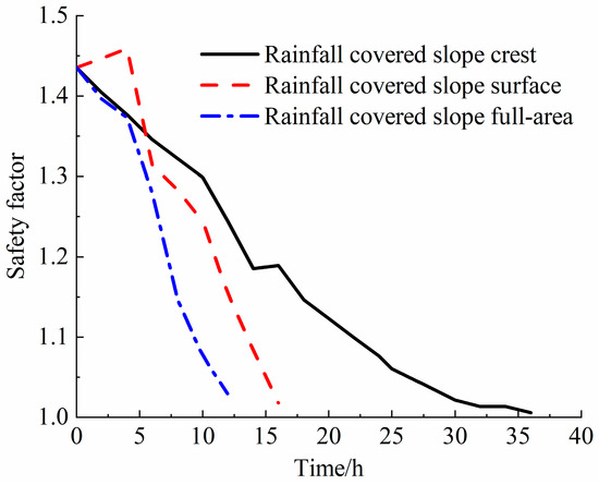
Figure 10.
Evolution law of the slope safety factor during rainfall.
A possible reason is that a small amount of rainwater infiltrates through the slope during the early stages of rainfall and the density of the soil increases. At the same time, the increase in moisture content leads to a reduction in the friction coefficient and cohesion, resulting in a decrease in the shear strength of the soil. Thus, the stability of the slope is reduced. Meanwhile, rainwater infiltration on the slope surface generates seepage forces in the direction of flow, where seepage forces perpendicular to the slope enhance slope stability, leading to an increase in slope stability. The reason for the slope safety factor initially increasing and then decreasing under slope surface rainfall conditions might be due to the reinforcing effect of the initial infiltration of rainwater on the slope.
5. Conclusions
This study presents a method of realizing rainfall infiltration by means of DEM simulations. Based on this approach, the influence of three infiltration boundary conditions on soil slope instability was investigated. The primary conclusions are as follows:
- (1)
- Rainfall infiltration boundaries significantly influenced the rainwater infiltration, the distribution of transient saturation zones, and seepage velocity. Under full-area infiltration conditions, the slope reaches failure earliest, while the rainfall-covered slope crest takes the longest time for failure to be induced. Rainwater penetration within the slope body is limited to a depth of 3.5 m or less at the time of slope instability.
- (2)
- For rainfall-covered slope surfaces, the slope stability and safety factors initially increase and then decrease, whereas the safety factor for rainfall-covered slope crests and full areas monotonically decrease as rainfall infiltration proceeds.
- (3)
- Various infiltration boundaries markedly affect the failure patterns of slopes. The failure surface of a slope covered by surface rainfall is prone to forming near the slope surface, which is narrow at both the top and bottom but wide in the middle. A rainfall-covered slope crest results in an arc-shaped failure which is wide at the top and narrow at the bottom. A slope with full-area rainfall has the shortest stability period and significant damage. The cracks extend towards the slope crest in a traction-like manner.
These findings could serve as references for failure mechanisms in rain-induced landslides.
Author Contributions
Conceptualization, X.S. and J.Z.; methodology, J.Z. and F.H.; software, Q.Z. and W.D.; validation, J.W. and L.Z.; formal analysis, F.H.; investigation, W.D. and L.Z.; resources, J.Z.; data curation, L.Z. and Q.Z.; writing—original draft preparation, J.Z. and F.H.; writing—review and editing, X.S. and Q.Z.; visualization, W.D. and J.W.; supervision, J.W.; project administration, X.S.; funding acquisition, J.Z. All authors have read and agreed to the published version of the manuscript.
Funding
This research was funded by the Basic Research Projects of Liaoning Provincial Department of Education (grant number: JYTQN2023279).
Data Availability Statement
Data were curated by the authors and are available upon request.
Conflicts of Interest
Author Jian Zhang was employed by the Liaoning Province Seventh Geological Brigade Co., Ltd. The remaining authors declare that the research was conducted in the absence of any commercial or financial relationships that could be construed as a potential conflict of interest.
References
- Lan, H.; Tian, N.; Li, L.; Wu, Y.; Macciotta, R.; Clague, J.J. Kinematic-based landslide risk management for the Sichuan-Tibet Grid Interconnection Project (STGIP) in China. Eng. Geol. 2022, 308, 106823. [Google Scholar] [CrossRef]
- Li, K.; Sun, P.; Wang, H.; Jian, R. Insight into failure mechanisms of rainfall induced mudstone landslide controlled by structural planes: From laboratory experiments. Eng. Geol. 2024, 343, 107774. [Google Scholar] [CrossRef]
- Li, Z.; Zhang, F.; Gu, W.; Dong, M. The Niushou landslide in Nanjing City, Jiangsu Province of China: A slow-moving landslide triggered by rainfall. Landslides 2020, 17, 2603–2617. [Google Scholar] [CrossRef]
- Di, B.; Stamatopoulos, C.A.; Stamatopoulos, A.C.; Liu, E.; Balla, L. Proposal, application and partial validation of a simplified expression evaluating the stability of sandy slopes under rainfall conditions. Geomorphology 2021, 395, 107966. [Google Scholar] [CrossRef]
- Ochiai, H.; Okada, Y.; Furuya, G.; Okura, Y.; Matsui, T.; Sammori, T.; Terajima, T.; Sassa, K. A fluidized landslide on a natural slope by artificial rainfall. Landslides 2004, 1, 211–219. [Google Scholar] [CrossRef]
- Bhattacherjee, D.; Viswanadham, B.V.S. Centrifuge Model Studies on Performance of Hybrid Geosynthetic–Reinforced Slopes with Poorly Draining Soil Subjected to Rainfall. J. Geotech. Geoenvironmental Eng. 2019, 145, 04019108. [Google Scholar] [CrossRef]
- Yuan, J.; Ye, C.; Pei, X.; Pei, Z.; Xie, Z.; Luo, L.; Yu, B. Runoff and soil loss characteristics on sandy soil slope with new chemical sand-fixing agent under simulated rainfall. Environ. Earth Sci. 2023, 82, 266. [Google Scholar] [CrossRef]
- Cho, S.E. Stability Analysis of Unsaturated Soil Slopes Considering Water-Air Flow Caused by Rainfall Infiltration. Eng. Geol. 2016, 211, 184–197. [Google Scholar] [CrossRef]
- Chen, X.; Zhang, L.; Zhang, L.; Zhou, Y.; Ye, G.; Guo, N. Modelling rainfall-induced landslides from initiation of instability to post-failure. Comput. Geotech. 2021, 129, 103877. [Google Scholar] [CrossRef]
- Chen, B.; Shui, W.; Liu, Y.; Deng, R. Analysis of Slope Stability with Different Vegetation Types under the Influence of Rainfall. Forests 2023, 14, 1865. [Google Scholar] [CrossRef]
- Khan, K.U.J.; Wang, C.-m.; Khan, M.W.J.; Liang, Z.; Li, S.; Li, B.-L. Influence of rainfall infiltration on the stability of unsaturated coal gangue accumulated slope. J. Mt. Sci. 2021, 18, 1696–1709. [Google Scholar] [CrossRef]
- Chang, W.; Wang, P.; Wang, H.; Shaofeng, C.; Yu, Y.; Xu, S. Simulation of the Q2 loess slope with seepage fissure failure and seismic response via discrete element method. Bull. Eng. Geol. Environ. 2021, 80, 3495–3511. [Google Scholar] [CrossRef]
- Li, W.C.; Li, H.; Dai, F.C.; Lee, L. Discrete element modeling of a rainfall-induced flowslide. Eng. Geol. 2012, 149–150, 22–34. [Google Scholar] [CrossRef]
- Wen, F.; Li, X.-A.; Yang, W.; Li, J.; Zhou, B.; Gao, R.; Lei, J. Mechanism of loess planar erosion and numerical simulation based on CFD–DEM coupling model. Environ. Earth Sci. 2023, 82, 197. [Google Scholar] [CrossRef]
- Su, H.; Fu, Z.; Gao, A.; Wen, Z. Particle Flow Code Method-Based Meso-scale Identification for Seepage Failure of Soil Levee. Transp. Porous Media 2017, 119, 311–336. [Google Scholar] [CrossRef]
- Hung, C.; Liu, C.-H.; Chang, C.-M. Numerical Investigation of Rainfall-Induced Landslide in Mudstone Using Coupled Finite and Discrete Element Analysis. Geofluids 2018, 2018, 9192019. [Google Scholar] [CrossRef]
- Zhang, H.; Zhang, B.; Wu, C.; Chen, K. Macro and micro analysis on coal-bearing soil slopes instability based on CFD-DEM coupling method. PLoS ONE 2021, 16, e0257362. [Google Scholar] [CrossRef]
- Peng, Y.; Yin, Z.-Y.; Ding, X. Micromechanical analysis of capillary suction effect on bearing capacity of unsaturated fine granular foundation soil using coupled CFD-DEM method. Comput. Geotech. 2022, 153, 105092. [Google Scholar] [CrossRef]
- Wang, Y.; Chai, J.; Xu, Z.; Qin, Y.; Wang, X. Numerical Simulation of the Fluid–Solid Coupling Mechanism of Internal Erosion in Granular Soil. Water 2020, 12, 137. [Google Scholar] [CrossRef]
- Su, H.; Li, H.; Zhang, L.; Wen, Z. Particle flow code method-based seepage behavior analysis and control effect evaluation for soil levee. Eng. Comput. 2020, 36, 97–114. [Google Scholar] [CrossRef]
- Li, X.; Lu, Y.; Wu, Y. Application of CFD-DEM coupling method in seepage-induced ground subsidence. J. Shanghai Univ. (Nat. Sci. Ed.) 2020, 26, 842–852. [Google Scholar]
- Geng, J.; Wang, Z.; Lan, X.; Li, X.; Zhang, D. Numerical simulation and safety distance analysis of slope instability of ionic rare earth tailings in different rainy seasons. Geomat. Nat. Hazards Risk 2023, 14, 2277127. [Google Scholar] [CrossRef]
- Gu, X.; Nie, W.; Li, Q.; Geng, J.; Zhou, T.; Yuan, C. Discrete Element Simulation of the Road Slope Considering Rainfall Infiltration. Water 2022, 2022, 3663. [Google Scholar] [CrossRef]
- Song, Y.; Lv, T.; Liu, H.; Huang, D.; Gu, D. Failure mechanism of the slope containing coarse particle enrichment zones located at the soil–rock interface under the heavy rainfall. Environ. Earth Sci. 2024, 83, 302. [Google Scholar] [CrossRef]
- Shi, C.; Si, X.; Zhang, Y.; Yang, J.; Dong, J. A simplified model for stability analysis of reservoir bank slopes under water level dropping condition. Granul. Matter 2022, 24, 90. [Google Scholar] [CrossRef]
- Daraei, R.; Herki, B.M.A.; Sherwani, A.F.H. Study of the Rapid Drawdown and Its Effect on Portal Subsidence of Heybat Sultan Twin Tunnels in Kurdistan-Iraq. Civ. Eng. J. 2017, 3, 496–507. [Google Scholar] [CrossRef]
- Zhao, W.; Mao, H.; Sun, L.; Lu, X.; Sun, S. Effect of Rainfall and Water Level Rise and Fall on Stability of Core Wall Embankment. Water 2024, 16, 3340. [Google Scholar] [CrossRef]
- Bao, X.; Liao, Z.; Xu, C.; Pang, X.; Xie, X.; Cui, H. Model test study of the failure of silty sand slope under different seepage boundary conditions. Rock Soil Mech. 2019, 40, 3789–3796. [Google Scholar] [CrossRef]
- Song, X.; Tan, Y.; Lu, Y.; Liu, J.; Liu, Y.; Wei, H.; Lai, K.; Xu, Z. Experimental and numerical studies on the instability of simple homogeneous sandy slopes under different infiltration scenarios. Chin. J. Rock Mech. Eng. 2024, 43, 1204–1218. [Google Scholar] [CrossRef]
- Richards, L.A. Capillary conduction of liquids through porous mediums. Physics 1931, 1, 318–333. [Google Scholar] [CrossRef]
- van Genuchten, M.T. A closed-form equation for predicting the hydraulic conductivity of unsaturated soils. Soil Sci. Soc. Am. J. 1980, 44, 892–898. [Google Scholar] [CrossRef]
- Mualem, Y. A new model for predicting the hydraulic conductivity of unsaturated porous media. Water Resour. Res. 1976, 12, 513–522. [Google Scholar] [CrossRef]
- Vauclin, M.; Khanji, D.; Vachaud, G. Experimental and numerical study of a transient, two-dimensional unsaturated-saturated water table recharge problem. Water Resour. Res. 1979, 15, 1089–1101. [Google Scholar] [CrossRef]
- Chen, N.S.; Zhou, W.; Yang, C.L.; Hu, G.S.; Gao, Y.C.; Han, D. The processes and mechanism of failure and debris flow initiation for gravel soil with different clay content. Geomorphology 2010, 121, 222–230. [Google Scholar] [CrossRef]
- Sun, L.; Tang, X.; Abdelaziz, A.; Liu, Q.; Grasselli, G. Stability analysis of reservoir slopes under fluctuating water levels using the combined finite-discrete element method. Acta Geotech. 2023, 18, 5403–5426. [Google Scholar] [CrossRef]
- Fredlund, D.G.; Morgenstern, N.R.; Widger, R.A. The shear strength of unsaturated soils. Can. Geotech. J. 1978, 15, 313–321. [Google Scholar] [CrossRef]
- Vanapalli, S.K.; Fredlund, D.G.; Pufahl, D.E.; Clifton, A.W. Model for the prediction of shear strength with respect to soil suction. Can. Geotech. J. 1996, 33, 379–392. [Google Scholar] [CrossRef]
- Lo, C.-M.; Lee, C.-F.; Huang, W.-K. Failure mechanism analysis of rainfall-induced landslide at Pingguang stream in Taiwan: Mapping, investigation, and numerical simulation. Environ. Earth Sci. 2016, 75, 1422. [Google Scholar] [CrossRef]
- Wang, X.; Xiao, L.; Zhao, J.; Ye, S.; Wei, J.; Huang, X. Analysis of the formation mechanism of a landslide in the lacustrine sediment of the Diexi ancient dammed lake in the upper reaches of the Minjiang River. Bull. Eng. Geol. Environ. 2022, 81, 328. [Google Scholar] [CrossRef]
- Gong, J.; Pang, X.; Tang, Y.; Yang, Z.; Jiang, J.; Ou, X. Effects of angularity and content of coarse particles on the mechanical behaviour of granular mixtures: A DEM study. Granul. Matter 2024, 26, 17. [Google Scholar] [CrossRef]
- Sun, Q.; Cheng, X.; Ji, S.; Jin, F. Advances in the micro-macro mechanics of granular soil materials. Adv. Mech. 2011, 41, 351–371. [Google Scholar]
- Ren, J.; Xiao, M.; Liu, G. Rock Macro–Meso Parameter Calibration and Optimization Based on Improved BP Algorithm and Response Surface Method in PFC 3D. Energies 2022, 15, 6290. [Google Scholar] [CrossRef]
- Su, H.; Li, H.; Hu, B.; Yang, J. A Research on the Macroscopic and Mesoscopic Parameters of Concrete Based on an Experimental Design Method. Materials 2021, 14, 1627. [Google Scholar] [CrossRef] [PubMed]
- Carsel, R.F.; Parrish, R.S. Developing joint probability distributions of soil water retention characteristics. Water Resour. Res. 1988, 24, 755–769. [Google Scholar] [CrossRef]
- He, Z.-m.; Tang, H.-l.; Deng, X. Effect of Seepage Force on Stability of High Embankment with Coarse-Grained Soil during Rainfall. J. Highw. Transp. Res. Dev. (Engl. Ed.) 2018, 12, 44–52. [Google Scholar] [CrossRef]
- Jian, Z.; Jiaquan, W.; Yuan, Z.; MinCai, J. Slope safety factor by methods of particle flow code strength reduction and gravity increase. Rock Soil Mech. 2009, 30, 1549–1554. [Google Scholar] [CrossRef]
- Lu, Y.; Tan, Y.; Li, X. Stability analyses on slopes of clay-rock mixtures using discrete element method. Eng. Geol. 2018, 244, 116–124. [Google Scholar] [CrossRef]


Disclaimer/Publisher’s Note: The statements, opinions and data contained in all publications are solely those of the individual author(s) and contributor(s) and not of MDPI and/or the editor(s). MDPI and/or the editor(s) disclaim responsibility for any injury to people or property resulting from any ideas, methods, instructions or products referred to in the content. |
© 2024 by the authors. Licensee MDPI, Basel, Switzerland. This article is an open access article distributed under the terms and conditions of the Creative Commons Attribution (CC BY) license (https://creativecommons.org/licenses/by/4.0/).