Article

Study on Impeller Optimization and Operation Method of Variable Speed Centrifugal Pump with Large Flow and Wide Head Variation

1
China Institute of Water Resources and Hydropower Research, Beijing 100083, China
2
Harbin Electric Machinery Company Limited, Harbin 150040, China
*
Author to whom correspondence should be addressed.
Water 2024, 16(6), 812; https://doi.org/10.3390/w16060812
Submission received: 29 January 2024 / Revised: 24 February 2024 / Accepted: 7 March 2024 / Published: 9 March 2024
(This article belongs to the Special Issue Advances in Hydrodynamics of Water Pump Station System)

Abstract

:
The benefits of variable speed centrifugal pumps include high stability, a broad operating range, and adjustable input power. In water distribution systems, the pump units are increasingly using variable speed technology. The energy-saving features and operational stability of the pump station are directly impacted by the hydraulic performance and the operation strategy. In this study, CFD numerical analysis and model tests were adopted to design and evaluate the hydraulic performance of the variable speed centrifugal pump with large flow and wide head variation in Liyuzhou Pump Station. Under the premise of ensuring the wide head variation, the optimized centrifugal pump met the requirements of hump margin and efficiency in the high head zone and the cavitation margin in the low head zone. The test results demonstrated that the operational range of the variable speed centrifugal pump was successfully widened by reasonable hydraulic parameters selection and impeller optimization. The safe and efficient operational range of the variable speed unit was determined by means of taking the performance requirements of the pump’s maximum input shaft power, cavitation characteristics and pressure fluctuation into consideration. The scientific and reasonable operational path to meet the various operation needs was also investigated and determined for the pump station’s actual operation needs. A high efficiency, safe operation, and a simplified control logic were achieved by using the operational path, which makes it a reasonable potential guide for hydraulic design and operational optimization of variable speed centrifugal pumps with large flow and wide head range.

1. Introduction

Large centrifugal pump stations play a critical role in long-distance water transfer projects and large-scale irrigation and drainage systems [1]. The performance of pumps, which are the core power equipment of pump stations, directly affects the energy-saving characteristics and operational stability of pump stations [2]. When pump stations require high hydraulic and energetic characteristics, larger flow rate range, larger pump station head range, it may be difficult for conventional fixed speed centrifugal pump to meet the all the operating conditions due to its relatively narrow efficiency range. To guarantee the stability and safety of the pump station during operation, the large-scale speed regulation operation strategy of centrifugal pumps is employed. The variable speed centrifugal pump offers several advantages over fixed speed centrifugal pump, including excellent stability, wide operating range, high hydraulic efficiency, and adjustable input power. Variable speed drives can increase the centrifugal pump’s stability and operational efficiency while allowing for control of the pump’s input power. However, within the variable speed operation range of the centrifugal pump, unstable hump characteristics and cavitation phenomena often occur, shortening the pump’s service life and reducing the reliability of its operation due to the generation of vibration and noise. Consequently, there are some restrictive technical problems involved in addressing the hump instability characteristic [3,4,5,6,7] and the cavitation characteristic [8,9,10,11,12,13] in the optimization design of the variable speed centrifugal pump.
Numerical estimation and performance analysis based on the CFD method have rapidly become the primary methods for designers due to the rapid development of computer fluid dynamics technology [14,15,16,17,18]. At the same time, many scholars have conducted comprehensive research on optimization methods [19,20], as well as on the monitoring and predicting of safe unit operation [21]. The flow characteristics of the centrifugal pump were simulated and analyzed using CFD, and the hydraulic performance was confirmed through the model test. Numerous domestic and international studies have been conducted in this field to optimize the design of centrifugal pumps. Cao [22] integrated CFD numerical simulation with response surface method to optimize guide vane centrifugal pumps. The Box–Behnken experiment design method was used to analyze 46 sets of hydraulic performance data, and the optimized model demonstrated a significant improvement in hydraulic performance compared to the original model. Yang [23] proposed a matching optimization on hydraulic components. Various approximate models were utilized to establish the relationship between the optimization design variables and the objective function. Reducing the number of layers and vanes of the diffuser and enhancing the matching of hydraulic components can dramatically improve the hydraulic performance and the hump instability characteristic of large vertical centrifugal pumps. Yuan [24] combined numerical simulation with prototype experiments and employed orthogonal experiment and the GA_PSO algorithm to improve the head variation and efficiency of the centrifugal pump with an elbow inlet. Sun [25] analyzed the influence of different blade numbers and structural designs on the cavitation performance and efficiency of the pump. The blade performance is evaluated comprehensively based on pressure distribution, flow conditions, cavitation, and the velocity diagram under different blade numbers. It is concluded that the efficiency of the four-blade pump was higher. Sun [26] combined Taguchi design and numerical calculations to enhance the efficiency and operational stability of an LVTCP, thereby reducing energy consumption. Based on the efficient house theory, a set of design schemes with the most extensive range of high-efficiency zones was calculated. These schemes improved the overall operating efficiency and stability of the storage pump under both design and non-design conditions. Hu [27] proposed an effective optimization design process for wide-output pump-turbines, highlighting the relationship between runner geometric characteristics and performance. The results indicate that the present approach can significantly improve the efficiency and stability.
However, the studies mentioned above mainly focused on fixed-speed centrifugal pumps. There are few papers studying the design methods of variable speed centrifugal pumps, and few applications of variable speed centrifugal pumps were reported in the literature. The design of a variable speed centrifugal pump can be completed by combining the design of a fixed speed centrifugal pump with the verification of variable speed operating conditions.
The operational stability and operating method of hydraulic mechanics have always been the key research topics of many scholars [28,29,30,31]. Merciera [32] studied the stability of pump operations of variable speed units under different control strategies. Theoretical and simulation analysis indicates that power control by speed can ensure the stability of the system. The research on the operation methods of variable speed units [33,34,35,36,37] has gradually become the prominent topic in the field of hydraulic mechanics. The advantages [38,39,40,41] and response characteristics [42] of variable speed operations for the hydraulic characteristics were also discussed by many researchers. However, there are few related studies in the literature on parameter selection, and there is currently no relevant research on methods to expand the operating area of centrifugal pumps.
This article intends to explore how to widen the operational range of the centrifugal pumps by optimizing the impeller. Firstly, this study involves the rational selection of operating parameters for the centrifugal pump. Secondly, it employs a fixed-speed optimization method to broaden its high efficiency area based on the selected centrifugal pump. Finally, the overall optimization of the centrifugal pump is carried out according to the variable speed operating range, considering the different characteristic requirements of the small flow and large flow areas. The effectiveness of this design approach and process has been verified in the Liyuzhou pump station in China. The research provides technical support for the application of centrifugal pump stations with large flow and wide head variation.

2. Hydraulic Design

2.1. Pump Station Parameter Analysis

In this article, the centrifugal pump with large flow and wide head range was used as the research object. The pump station has eight installed variable centrifugal pump units with a total flow rate of 80 m3/s, and is the centrifugal pump station with the largest single design flow in China. The pump station’s overall flow varies between 20 m3/s and 80 m3/s. The maximum head of the centrifugal pump is 48.0 m, and the minimum head is 16.3 m. Although the pump station head is not high, the relative amplitude of the head is enormous, and the ratio of the maximum head to the minimum head reaches K = 2.945. Table 1 presented the main parameters of the variable centrifugal pump unit. The specific speed, i.e., ns = 202.5, and the formula are shown in Equation (1).
n s = 3.65 × n × Q H 3 4
where ns denotes the specific speed of the pump, n is the rotating speed (r/min), Q represents the mass flow rate of design point (m3/s), and H stands for the pump head (m).
According to the analysis of the main technical parameters of the pump station, the project required a wide range of speed regulation operation to accommodate the wide range operation capacity of the pump and to ensure the safe and stable operation of the pump station. The variable speed operating range and power regulation capability of a centrifugal pump are closely related to its parameter selection and hydraulic design. Due to the relatively small high-efficiency operating region, fixed speed centrifugal pumps are unable to fully meet the performance demands of pump stations with wide head variation. At present, there is no large centrifugal pump in China that can meet the performance requirement of the pump station implemented in this project.

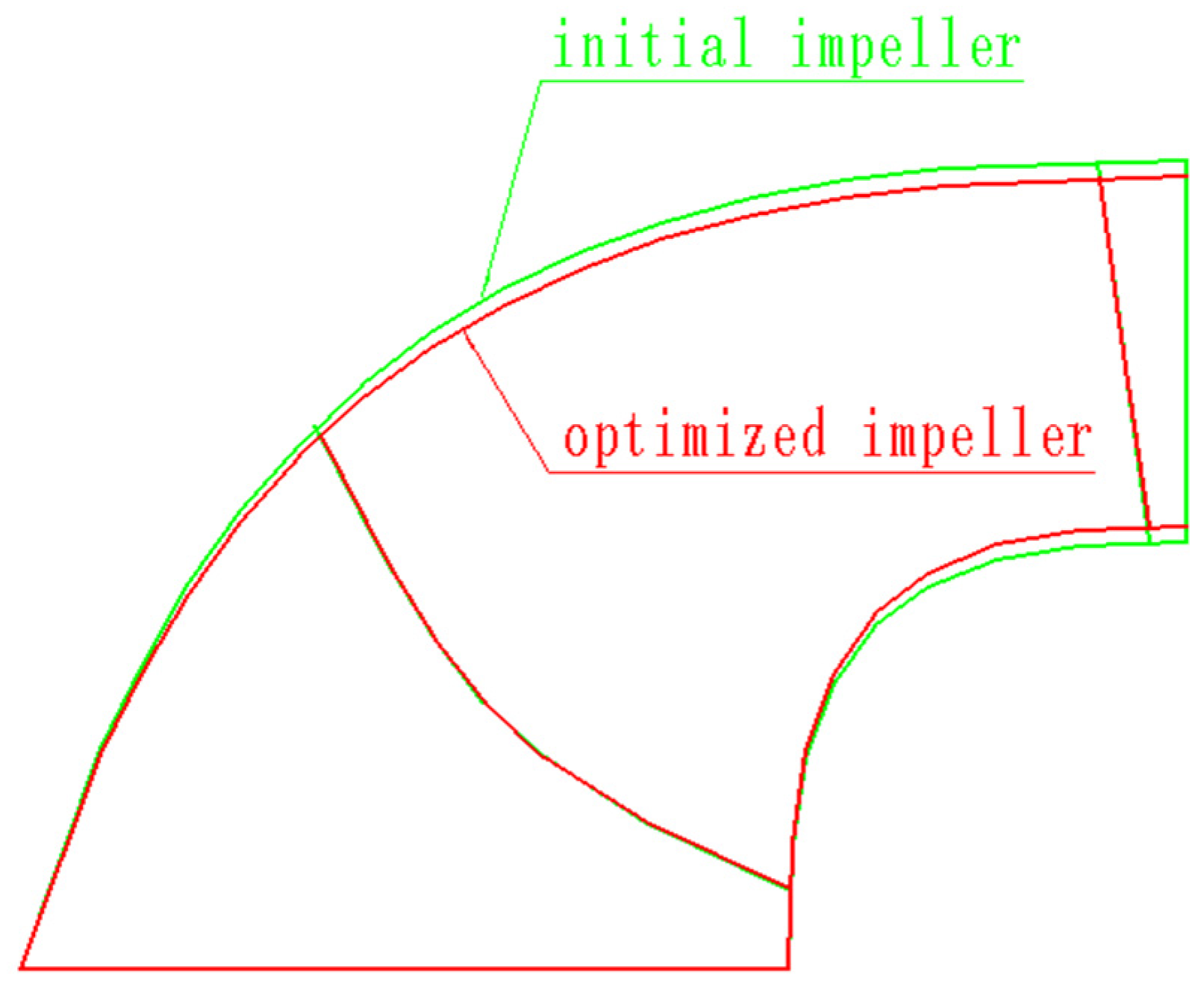
2.2. Impeller Optimization Design

Based on the complex hydraulic conditions, such as large flow rates, wide head ranges, and high stability, the parameters selection and calibration method are systematically analyzed initially. Aiming at examining the pump station’s wide head variation characteristics, the hydraulic design must not only satisfy the requirements for high efficiency levels and hump margin but also regulate cavitation performance within a reasonable range. A variable speed centrifugal pump has the characteristics of flexible operation. As shown in Figure 1, the centrifugal pump can operate at different head conditions at variable speed, such as point A, point A′ and point A″, which are similar operating points; conversely, the input power of the pump can be changed by changing the rotational speed, such as point A and point B, in which case the head maintained stable while the flow rate and input power changed.
According to the operation characteristics and performance requirements of the centrifugal pump, the whole channel is designed based on parameter selection. The draft tube, impeller, guide vane, and volute are the four primary flow components of a centrifugal pump. The geometric parameters of draft tube and volute should be adjusted to the pumping station’s specifications before conducting CFD calculation and performance studies. To minimize the hydraulic loss of the guide vane, it is important to optimize not only the airfoil profile but also the relative position connection between the guide vane and the impeller, as well as the appropriate size of the vaneless area. Additionally, maintaining the width of the impeller in proportion to the guide vane aperture is crucial.
The hydraulic design of the impeller, which is the core energy conversion equipment of the centrifugal pump, directly affects the overall performance of the centrifugal pump. The pump station belongs to the medium–high specific speed centrifugal pump. During the preliminary model selection process, the hydraulic model with a similar specific speed is selected as the initial impeller. The main geometric parameters of the initial impeller are shown in Table 2. The rated rotation speed characteristic curve of the initial impeller prototype centrifugal pump (Test) are shown Figure 2.
In Figure 2, the intersection point of the blue dashed lines is the design condition point of centrifugal pump. The hump margin of centrifugal pump is less than 2% at the location of red circles in the operating area of pump station. Analyzing the initial impeller based on the model test indicated that the cavitation performance and hump margin are difficult to meet the performance requirements. Therefore, the initial impeller, the impeller geometry, blade profile, exit edge, wrap angle, and inlet blade angle for the centrifugal pump to be developed were all improved to enhance cavitation performance and characteristics of hump instability. The targeted hydraulic design is determined by considering the operational features of the pump station and then combining the reasonable requirements for hydraulic performance between the minimum head and the maximum head. Firstly, during the impeller hydraulic design process, the small flow hump margin should be guaranteed to meet the requirements of the centrifugal pump running at low speed, thereby enhancing the water supply guarantee rate and ensuring the unit’s excellent hydraulic properties. Secondly, the cavitation characteristics are improved to ensure the safe and stable operation of the pump station within its operational range.
The cavitation performance is improved by optimizing the shape of the blade inlet edge and the placement angle of the blade inlet. To improve the pressure fluctuation characteristics, the matching relationship between the impeller and guide vane, as well as the vaneless zone width was optimized. By decreasing the guide vane height and strengthening the internal flow characteristics between the guide vane and impeller under small flow conditions, the hump margin was also increased. Numerical simulation results indicate that the optimized impeller has better energy characteristics, cavitation characteristics, and hump margin than the initial impeller. Following repeated calculations, analyses, and adjustments, the hydraulic performance meets the operational requirements of the pump station. The rated speed characteristic comparison curves of the initial impeller and optimized impeller prototype centrifugal pumps (CFD and Test) are shown Figure 3 and Figure 4, respectively.
The main geometric parameters of the optimized impeller are shown in Table 3, and the comparison of model impeller meridian flow channel are shown in Figure 5. The comparison of model impeller blades are also shown Figure 6, where the green part is the initial impeller and the red part is the optimized impeller.

3. Performance Estimation Method

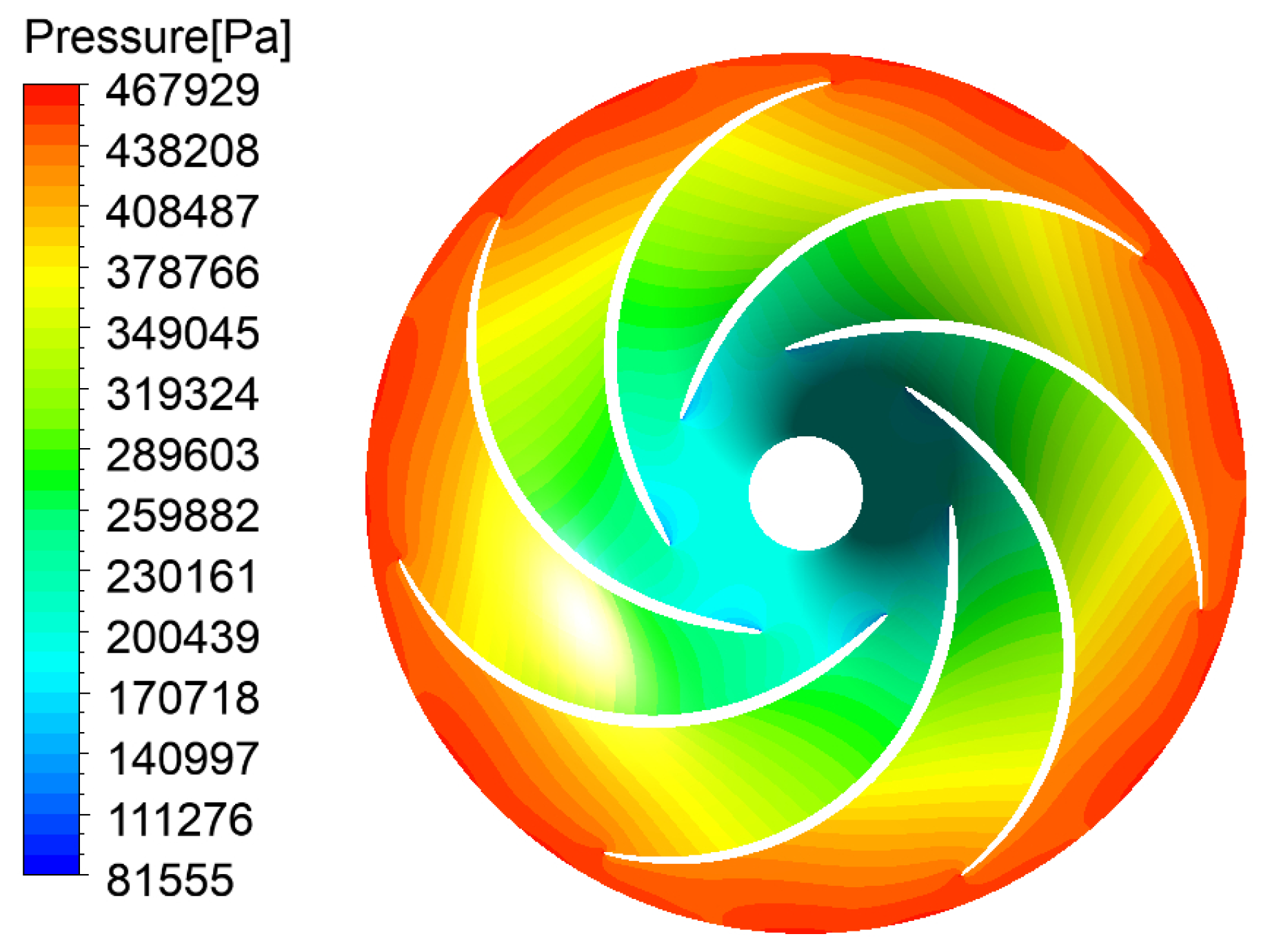
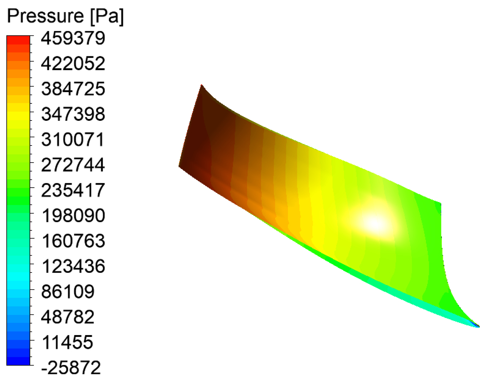
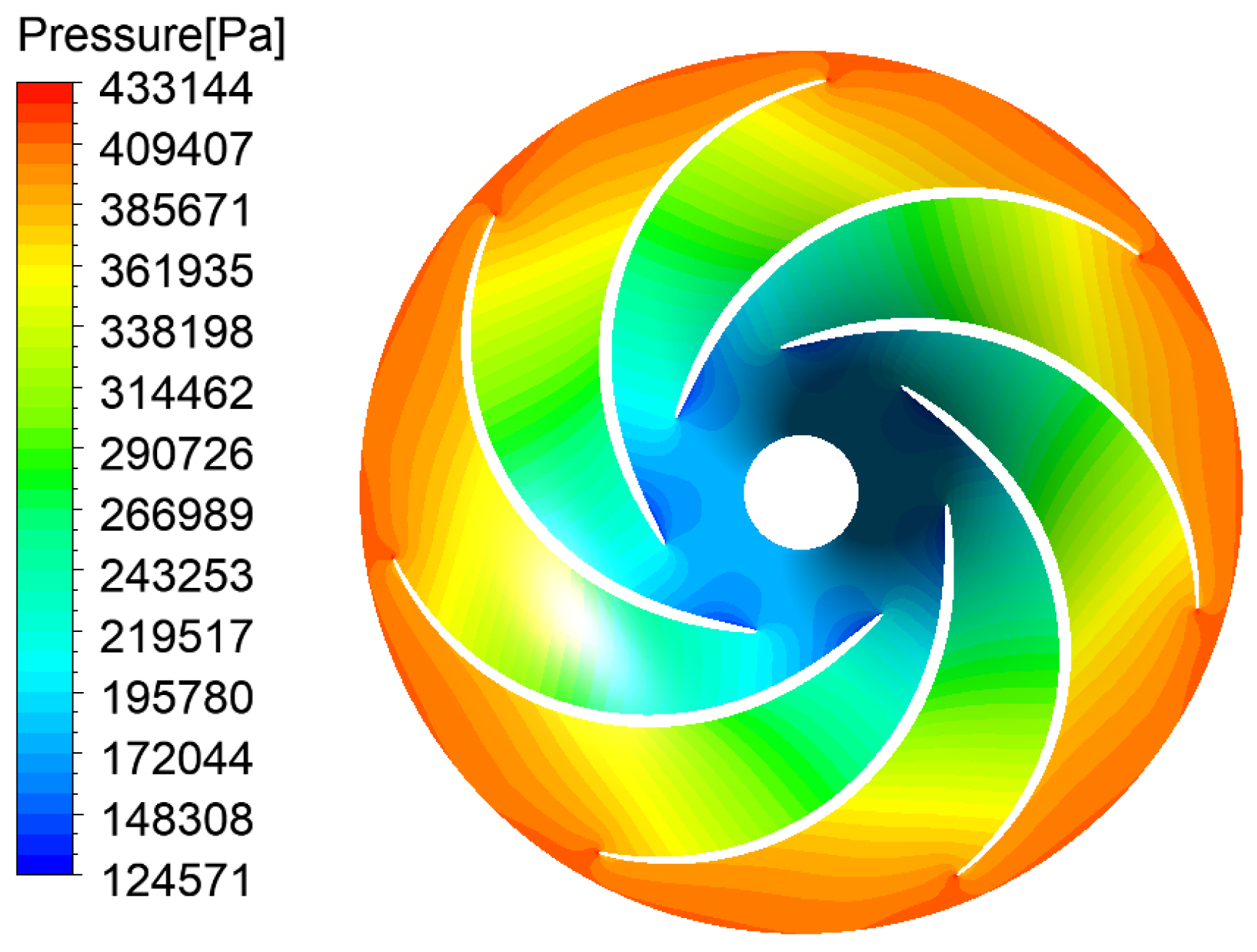
3.1. CFD Numerical Calculation Method

In this article, the simulation computation of the whole flow channel is conducted for a large centrifugal pump. Flow characteristics and pressure distribution in the internal flow field are obtained to provide essential data for the performance analysis and optimization of the centrifugal pump.
Pre-processing is essential for numerical simulation, including solid modeling and mesh division. The overall calculation domain of centrifugal pumps is divided into three main parts: the volute and guide vane domain, the impeller domain, and the draft tube domain. The calculation domain model of centrifugal pumps is shown in Figure 7.
The computational grid for the three calculation domains were generated respectively, and the division of the regional mesh was refined to ensure precise representation. To improve the calculation speed and accuracy of iterative calculations in the simulation, a grid independence check was carried to determine the number of grids for final calculation. According to the numerical calculation results of centrifugal pump efficiency and head, when the grid number of grid elements exceeds 5.71 × 10⁶, the head and hydraulic efficiency tends to be stable. The number of grid elements for volute and guide vanes domain, impeller domain, and draft tube domain were 2.2 million, 2.4 million, and 1.1 million, respectively. The grids for each part are shown in Figure 8.
To obtain the flow characteristics and pressure distribution in the internal flow field of centrifugal pump, this article adopts the software SST (shear stress transport) turbulence model to carry out numerical simulation of the computational model. The SST turbulence model consists of the turbulent kinetic energy transport equation and the turbulent dissipation rate transport equation, providing accurate predictions for flow separation under reverse pressure gradients.
For boundary conditions, the mass flow rate is used as the inlet boundary condition for the draft tube, the outlet condition for the volute is defined by setting the mean static pressure to 0 pa, the standard wall function is used in the near wall area, and the wall is without any slip boundary conditions.
For the impeller and the guide vane, the static interface adopts the stage interface transfer model. To ensure consistency with the model test and facilitate data analysis and further optimization design, the model rotated speed is set to 1200 r/min. To keep the boundary conditions similar to the real conditions, the reference pressure was set as 101.325 kPa. The solver is set to the higher order solution mode, and the standard of convergence is the residual of the continuity and momentum equations with a value of 1 × 10⁻⁴.

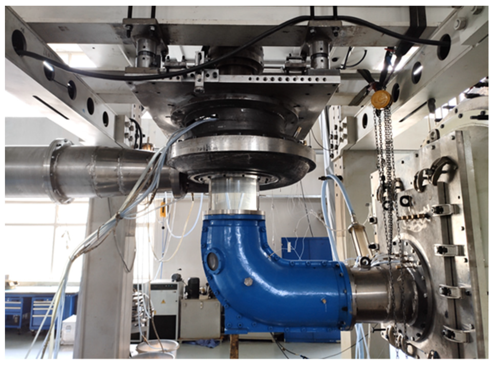
3.2. Model Test Validation Method

The hydraulic performance of the variable-speed centrifugal pump developed by the numerical calculation method is further validated through the model test method. The model test was carried out at a hydraulic mechanical model test rig, as shown in Figure 9.
A model test rig is a hydraulic mechanical test rig with high parameters and high precision, primarily for pump and pump turbine testing. The uncertainty in efficiency is less than ±0.2%.
The model test includes examining energy characteristics, cavitation characteristics, runaway speed characteristics, pressure pulsation characteristics, water thrust, and other test items. All test items are conducted on the same test rig and model device.
Efficiency testing primarily focuses on measuring the efficiency, flow rate, and head of centrifugal pump in clear water. It includes efficiency characteristics of the expected frequency change range and frequency (speed) within the operating range. The reference surface of the plant cavitation is the centerline of the guide vane, and the cavitation tests are conducted in the whole operating range of the centrifugal pump. Lastly, the incipient cavitation coefficient, σi, and the critical cavitation coefficient, σ1, corresponding to the different operating conditions are determined.

4. Performance Evaluation and Result Analysis

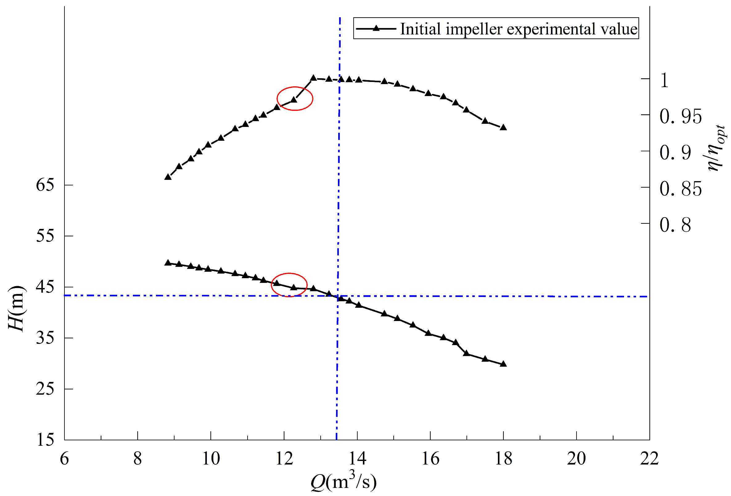
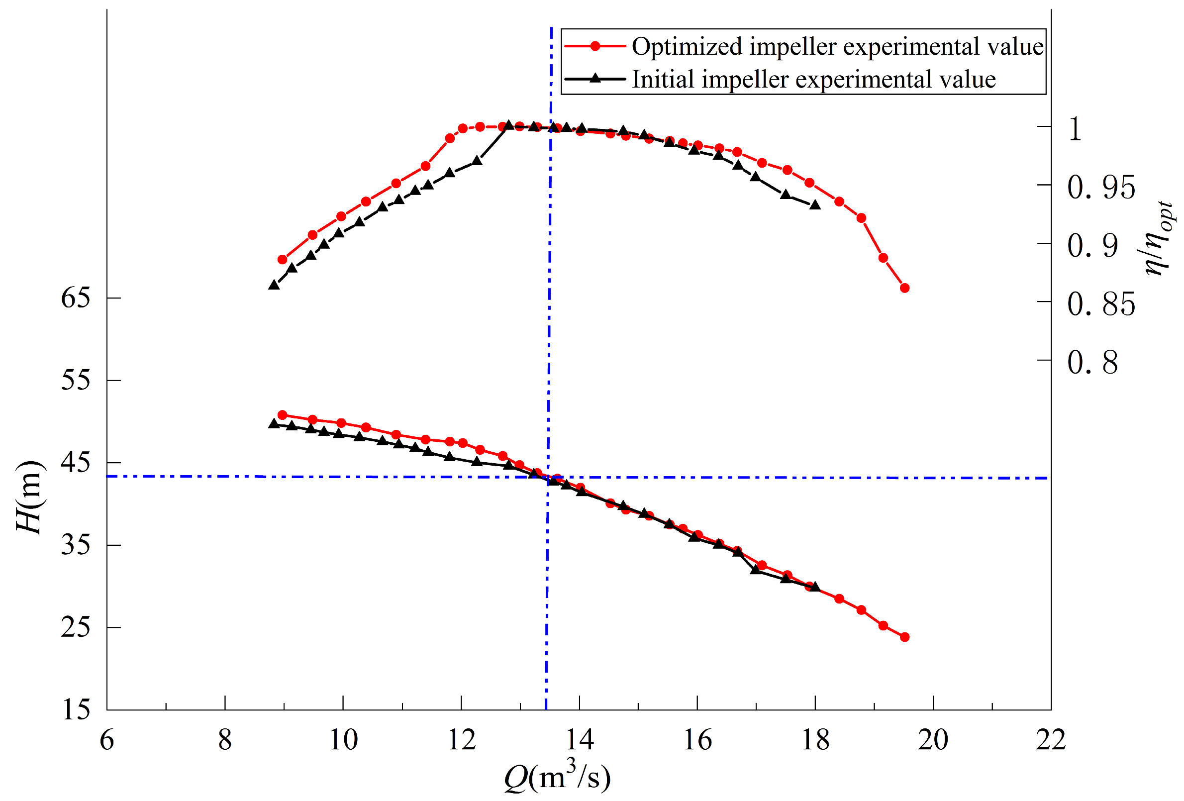
4.1. Centrifugal Pump Performance Evaluation

The centrifugal pump should be capable of reducing flow while maintaining good operating efficiency in the low head zone when the pump station is close to the rated head. It is necessary to maintain the same flow under various head situations. Therefore, the centrifugal pump must possess the following characteristics: a reasonably wide high-efficiency zone and a cavitation-free zone of operation; its wide-range speed strategy can match the operational requirements. The flow characteristic and pressure distribution of the centrifugal pump are analyzed, and the impeller’s overall performance level is estimated using the CFD numerical simulation. To validate the effectiveness of performance compliance, tests are conducted on the designed impeller.
This article adopts the model centrifugal pump as the numerical calculation model. It focuses on analyzing the internal flow field of the maximum head, design head, and the minimum head frequency conversion conditions (i.e., operating 65% of the rated speed to maintain the designed flow of the pump). The main parameters of the calculation condition point of the centrifugal pump are shown in Table 4.
The impeller internal pressure distribution and streamline under maximum head conditions are depicted in Figure 10 and Figure 11. It can be observed that internal pressure within the impeller is uniform, with static pressure gradually increasing from the impeller’s inlet to outlet. Additionally, the internal streamline within the impeller is uniformly distributed, with fluid velocity gradually increasing.
The pressure distribution of the pressure surface and suction surface is uniform based on Figure 12 and Figure 13, indicating that there is no prominent low pressure local area. This suggests that the energy conversion on the blade is uniform.
Figure 14 and Figure 15 show the distribution of the internal pressure and streamline of the impeller under the design head condition. The figures show that the internal pressure gradient of the impeller changes uniformly, and the internal streamline of the impeller is evenly distributed without local turbulence and vortex flow.
Figure 16 and Figure 17 indicate that there is no obvious local low-pressure area on the blade surface, with uniform pressure distribution observed on both the pressure surface and the suction surface of the blade; this indicates that the energy conversion on the blade is uniform. Following similar rules, the centrifugal pump has good internal flow field distribution characteristics at similar working conditions at different speeds.
Figure 18, Figure 19, Figure 20 and Figure 21 show the CFD numerical calculation results of the minimum head frequency conversion condition (65% rated speed). Given that the minimum head of the pump is low, the frequency conversion adjustment is adopted to ensure the efficient and stable operation of the pump. So that the pump can still maintain a good running condition at the minimum head. It can be seen from the figure that the internal pressure variation with the impeller is uniform, and the streamline distribution inside the impeller is reasonable. The pressure gradient of impeller blade is reasonably distributed, with no obvious uneven pressure distribution.
To facilitate comparison, the model head, flow, efficiency, and other parameters are transformed into prototype values using the similarity law. The numerical calculation and experimental values of the prototype energy characteristic parameters for the rated speed condition are contrasted in Figure 22. The horizontal axis represents the flow Q (m3/s), and the vertical axis represents the head H (m) and the relative efficiency of the centrifugal pump η/ηopt, respectively. The intersection point of the blue dashed lines is the design head and design flow and the red circle is the optimum operating condition point. The centrifugal pump has great operating efficiency at design conditions, as demonstrated by the red lines in Figure 22. It maintains this level of efficiency throughout a wide operating region (11 m3/s–17 m3/s) near the rated flow rate (η/ηopt > 0.975).
The black lines represent the test results. Under design conditions, the test results are consistent with the CFD numerical results in predicting the head and efficiency, thus verifying the accuracy of the numerical simulations. Near the design condition, there is a high coincidence and trend within test results and the CFD numerical results, which indicates that CFD calculations accurately predict the hydraulic characteristics of the centrifugal pump.

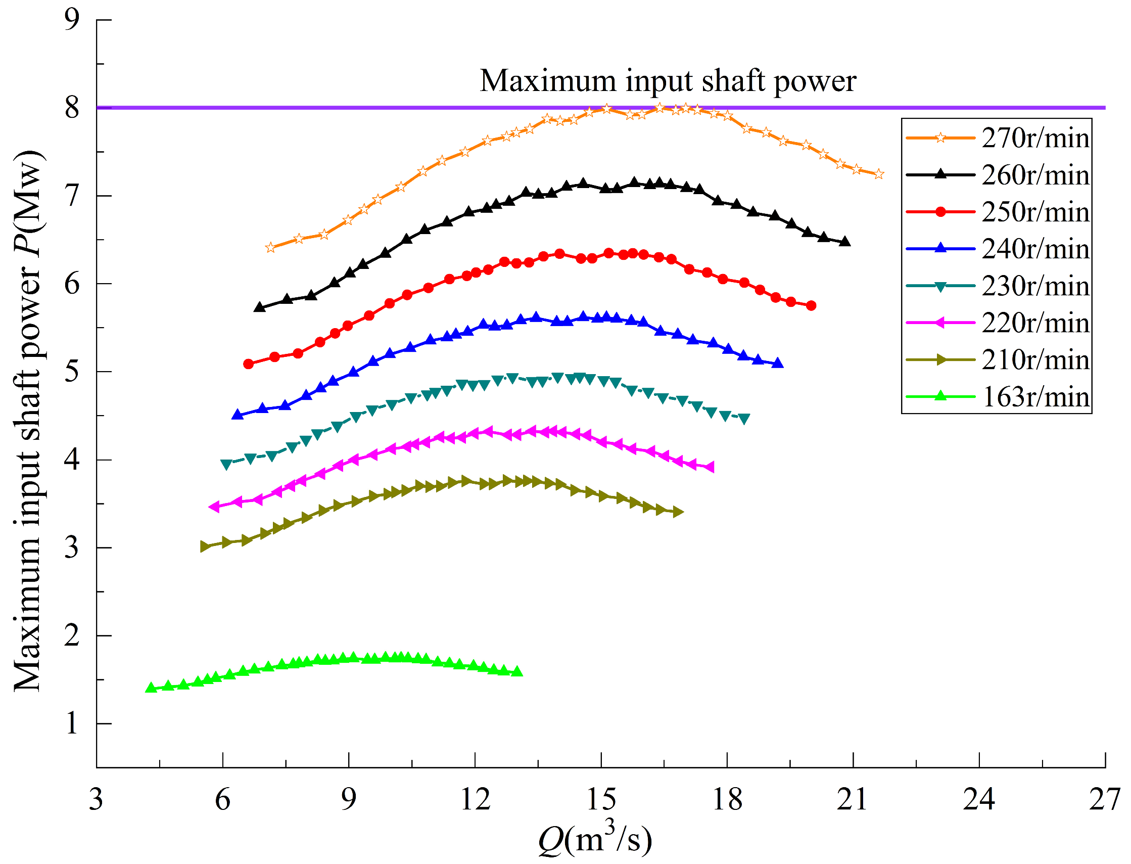
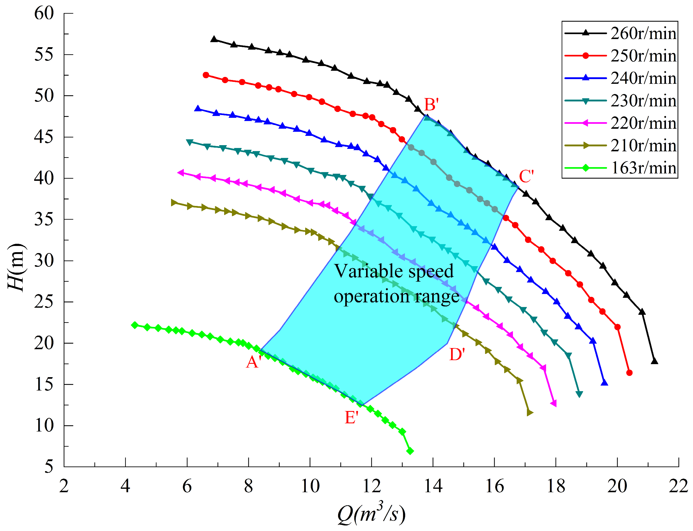
4.2. Variable Speed Operating Characteristics Analysis

The energy characteristic curve obtained from the model test at the rated speed is converted into the prototype energy characteristic curve by the similarity rule. Figure 23 illustrates the variable speed characteristic curves of the prototype pump at different rotated speeds. In Figure 23, point A, point A′ and point A″ are the optimal operating points of the centrifugal pump under the design head, minimum head and maximum head conditions, respectively.
From the flow, head, and efficiency parameters in Figure 23, the maximum input shaft power curve of the centrifugal pump at different rotational speeds can be calculated. Figure 24 illustrates the correlation between the rated speed and the maximum input shaft power at each operating condition. Considering the motor capacity of the pump station has been determined and the allowance is required, the maximum rotation speed of the centrifugal pump is determined to be 260 r/min.
The incipient cavitation curve coefficient is displayed in Figure 25 for various operating conditions. When the plant cavitation coefficient is high, the head is low, and the downstream level is high. When the plant cavitation coefficient is low, the head is high, and the downstream level is low. Figure 25 illustrates that when the pump is operating at high speeds, the incipient cavitation coefficient is consistently smaller than the plant cavitation coefficient. This indicates that, under appropriate operating conditions, the centrifugal pump can operate cavitation-free.
The variable speed pump unit operates within a range which is limited by the rated speed, maximum input shaft power, hydraulic efficiency, hump margin, pressure pulsation, and the cavitation limit in the low head.
Based on the above analysis, the pump operating zone shall be determined by multiple boundaries: the maximum rotational speed and maximum input shaft power line pump curve (B′–C′), the cavitation line (C–D′), the hump margin line (A′–B′), the minimum variable speed limit (A′–E′) and the relatively high efficiency line (D′–E′). If the boundary lines intersect, the part within the intersection point is taken as the operating area. The final safe and efficient variable speed operating zone is shown as the blue area in Figure 26. The variable speed operation of the centrifugal pump can ensure efficient and stable operation without cavitation in this zone.
To meet the actual requirements of the pump station and facilitate the actual operational management, the operation path can be further established. This path aims to ensure the simplicity of operation and maintenance of the pump station while enhancing the efficiency and stability.
When the head required by the pump station ranges from 25.5 m to 48.0 m, the appropriate speed can be selected to keep the rated flow unchanged, as shown in Figure 27. The intersection point of the blue dashed line (Q = 13.5 m3/s) and the head curve of different speeds (210 r/min–260 r/min) represents the operating condition under different heads. From the position of the intersection point between the blue dashed line and the efficiency curve, we can see that the efficiency points for these operating conditions are concentrated and high.
If the pump station flow is maintained at the rated flow when its head approaches the minimum head of 16.3 m, hydraulic efficiency will further decline. Meanwhile, reducing the flow rate should ensure the high level of efficiency. The rated speed design point A in Figure 1 is comparable to A′, and the orange square in the high efficiency zone represents the corresponding efficiency of point A′. Consequently, by decreasing the rotation speed (163 r/min–210 r/min), the pump station can operate along the orange dotted line when the pump station head ranges from 16.3 m to 25.5 m.
In summary, the characteristics of small flow hump and large flow cavitation can be improved to achieve wide operating range of variable speed centrifugal pump. For specific pumping stations, appropriate operation paths can be selected according to the actual operation requirements to simplify the operation and ensure the efficiency and stability within the operation range.

5. Conclusions

This study investigates and optimizes a variable speed centrifugal pump through a combination of numerical simulation and model testing. The analysis aims to establish optimal design rationality between the maximum head hump margin and the minimum head cavitation characteristics under the large flow and wide head variation conditions by adjusting the shape of the blade inlet edge and the blade inlet airfoil, improve the small flow hump characteristics through optimizing the matching relationship between the guide blade and the impeller, and improve the pressure pulsation characteristics by optimizing the width of the vaneless area. The centrifugal pump that can satisfy the project’s needs is obtained by continuously modifying the geometric flow channel and impeller parameters. The project achieves the goal of expanding the variable speed centrifugal pump’s wide operating range. We can effectively increase the centrifugal pump’s operating range and safety stability in the high efficiency area by using numerical optimization technology and model testing methods. The study also offers a technical guarantee for the pump unit’s wide range of variable speed operations.
To achieve high efficiency and stability across the whole operating range, this article focused on analyzing the pump station’s suitable operation path in accordance with its actual operation needs. The operation strategy of the variable speed centrifugal pump is proposed for various operating conditions, creating a combined operation mode that maintains an efficient operation in low head area while maintaining steady flow rate in the high head area. The research results can function as a reference for the optimal design of large flow and wide range variable speed centrifugal pumps and reasonable operation of units in the future.

Author Contributions

Methodology, G.Z.; software, P.X. and Y.T.; validation, C.Z. and X.W.; writing—original draft, Y.Z.; supervision, L.M. All authors have read and agreed to the published version of the manuscript.

Funding

This research was funded by the IWHR Research & Development Support Program (HM0145B012021).

Data Availability Statement

The data presented in this study are available on request from the corresponding author. The data are not publicly available due to engineering technical requirements.

Conflicts of Interest

Author Guang Zhang was employed by the company Harbin Electric Machinery Company Limited. The remaining authors declare that the research was conducted in the absence of any commercial or financial relationships that could be construed as a potential conflict of interest.

References

  1. Shi, X.; Lu, J.; Zhao, L. Investigations on the influence of tandem blades on inner flow and performance characteristics of centrifugal pump. Proc. Inst. Mech. Eng. Part E J. Process Mech. Eng. 2020, 234, 46–55. [Google Scholar] [CrossRef]
  2. Torii, D.; Nagahara, T.; Okihara, T. Suppression of the secondary flow in a suction channel of a large centrifugal pump. IOP Conf. Ser. Mater. Sci. Eng. 2013, 52, 032005. [Google Scholar] [CrossRef]
  3. Ramirez, R.; Avila, E.; Lopez, L.; Bula, A.; Forero, J.D. CFD characterization and optimization of the cavitation phenomenon in dredging centrifugal pumps. Alex. Eng. J. 2020, 59, 291–309. [Google Scholar] [CrossRef]
  4. AI-Obaidi, A.R.; Towsyfyan, H. An experimental study on vibration signatures for detecting incipient cavitation in centrifugal pumps based on envelope spectrum analysis. J. Appl. Fluid Mech. 2019, 12, 2057–2067. [Google Scholar]
  5. Wang, D.; Liu, Z.; Han, W. Study on improving cavitation performance of centrifugal Pump by Perforation at the Front Cover Plate. Int. J. Fluid Mach. Syst. 2020, 13, 668. [Google Scholar]
  6. Hesamedin, K.; Abdolah, S.; Siamak, H. Improvement of the centrifugal pump performance by restricting the cavitation phenomenon. Chem. Eng. Trans. 2018, 71, 1369–1374. [Google Scholar]
  7. Song, P.; Wei, Z.; Zhen, H.; Liu, M.; Ren, J. Effects of pre-whirl and blade profile on the hydraulic and cavitation performance of a centrifugal pump. Int. J. Multiph. Flow 2022, 157, 104261. [Google Scholar] [CrossRef]
  8. Yang, G.; Shen, X.; Shi, L.; Zhang, D.; Zhao, X.; van Esch, B.P.M. Numerical investigation of hump characteristic improvement in a large vertical centrifugal pump with special emphasis on energy loss mechanism. Energy 2023, 273, 127163. [Google Scholar] [CrossRef]
  9. Ye, C.; Wang, C.; Yan, H.; Wang, F.; Zheng, Y.; van Esch, B.P.M. Investigation on transition characteristics of laminar separation bubble on a hydrofoil. Phys. Fluids 2023, 35, 105154. [Google Scholar] [CrossRef]
  10. Ye, C.; Tang, Y.; An, D.; Wang, F.; Zheng, Y.; van Esch, B.P.M. Investigation on stall characteristics of marine centrifugal pump considering transition effect. Ocean Eng. 2023, 280, 114823. [Google Scholar] [CrossRef]
  11. Feng, J.; Ge, Z.; Yang, H.; Zhu, G.; Li, C.; Luo, X. Rotating stall characteristics in the vaned diffuser of a centrifugal pump. Ocean Eng. 2021, 229, 108955. [Google Scholar] [CrossRef]
  12. Wang, Y.; Ding, Z. Optimization design of hump phenomenon of low specific speed centrifugal pump based on CFD and orthogonal test. Sci. Rep. 2022, 12, 12121. [Google Scholar]
  13. Li, P.; Li, N.; Tao, R.; Lu, Z.; Zhu, D.; Liu, W.; Yao, Z.; Xiao, R. Quantitative investigation of the head-hump of large-scale vaned-voluted centrifugal pump. Proc. Inst. Mech. Eng. Part C J. Mech. Eng. Sci. 2022, 236, 10779–10791. [Google Scholar] [CrossRef]
  14. De Donno, R.; Ghidoni, A.; Noventa, G.; Rebay, S. Shape optimization of the ERCOFTAC centrifugal pump impeller using open-source software. Optim. Eng. 2019, 20, 929–953. [Google Scholar] [CrossRef]
  15. Wang, Y.; Zhou, L.; Han, M.; Shen, L. Performance Prediction of an Optimized Centrifugal Pump with High Efficiency. Fluid Dyn. Mater. Process. 2023, 19, 2215–2228. [Google Scholar] [CrossRef]
  16. Huang, R.; Zhang, Z.; Zhang, W.; Mou, J.; Zhou, P.; Wang, Y. Energy performance prediction of the centrifugal pumps by using a hybrid neural network. Energy 2020, 213, 119005. [Google Scholar] [CrossRef]
  17. Ramadhan, A.A.; Ali, Q. Effect of outlet impeller diameter on performance prediction of centrifugal pump under single-phase and cavitation flow conditions. Int. J. Nonlinear Sci. Numer. Simul. 2022, 23, 1203–1229. [Google Scholar]
  18. Dong, J.; Li, W. Numerical simulation of centrifugal pump cavitation based on ANSYS. J. Phys. Conf. Ser. 2023, 2450, 012031. [Google Scholar] [CrossRef]
  19. Mahdi, M.T.; Amin, D.A.; Ahmad, H.; Mohamed BB, H.; Mohsen, I. MLP and optimized FCM-ANFIS models pro-posed for inlet turbulent flow under ultrasonic vibration. J. Therm. Anal. Calorim. 2023, 148, 13995–14009. [Google Scholar]
  20. Morteza, E.; Amin, D.A.; Ali, J. Optimization of ultrasonic-excited double-pipe heat exchanger with machine learning and PSO. Int. Commun. Heat Mass Transf. 2023, 147, 106985. [Google Scholar]
  21. Li, L.; Xu, W.; Tan, Y.; Yang, Y.; Yang, J.; Tan, D. Fluid-induced vibration evolution mechanism of multiphase free sink vortex and the multi-source vibration sensing method. Mech. Syst. Signal Process. 2023, 189, 110058. [Google Scholar] [CrossRef]
  22. Cao, W.; Wang, H.; Yang, X.; Leng, X. Optimization of Guide Vane Centrifugal Pumps Based on Response Surface Methodology and Study of Internal Flow Characteristics. J. Mar. Sci. Eng. 2023, 11, 1917. [Google Scholar] [CrossRef]
  23. Yang, G.; Zhao, X.; Zhang, D.; Geng, L.; Yang, X.; Gao, X. Hydraulic components’ matching optimization design and entropy production analysis in a large vertical centrifugal pump. J. Mech. Sci. Technol. 2021, 35, 5033–5048. [Google Scholar] [CrossRef]
  24. Yuan, Y.; Jin, R.; Tang, L.; Lin, Y. Optimization Design for the Centrifugal Pump under Non-Uniform Elbow Inflow Based on Orthogonal Test and GA_PSO. Processes 2022, 10, 1254. [Google Scholar] [CrossRef]
  25. Sun, X.; Zhu, R.; Wang, J.; Li, Y. Effect analysis of centrifugal pump parameters optimization design on performance. J. Phys. Conf. Ser. 2023, 2599, 012034. [Google Scholar] [CrossRef]
  26. Sun, J.; Pei, J.; Wang, W. Effect of impeller and diffuser matching optimization on broadening operating range of storage pump. J. Energy Storage 2023, 72, 108737. [Google Scholar] [CrossRef]
  27. Hu, Z.; Cheng, Y.; Liu, D.; Chen, H.; Ji, B.; Ding, J. Broadening the operating range of pump-turbine to deep-part load by runner optimization. Renew. Energy 2023, 207, 73–88. [Google Scholar] [CrossRef]
  28. Iliev, I.; Trivedi, C.; Dahlhaug, O.G. Variable-speed operation of Francis turbines: A review of the perspectives and challenges. Renew. Sustain. Energy Rev. 2019, 103, 109–121. [Google Scholar] [CrossRef]
  29. Badshah, M.; Badshah, S.; Jan, S. Comparison of computational fluid dynamics and fluid structure interaction models for the performance prediction of tidal current turbines. J. Ocean Eng. Sci. 2020, 5, 164–172. [Google Scholar] [CrossRef]
  30. Nasir, U.; Iqbal, Z.; Rasheed, M.; Minxiao, H. Active and reactive power control of a variable speed pumped storage system. In Proceedings of the 2015 IEEE 15th International Conference on Environment and Electrical Engineering (EEEIC), Rome, Italy, 10–13 June 2015; pp. 6–11. [Google Scholar]
  31. Li, Y.; Yang, W.; Huang, Y.; Ma, W.; Zhao, Z.; Yang, J.; Yang, J. Variation law of pressure pulsation during variable speed operation of pumped storage units. IOP Conf. Ser. Earth Environ. Sci. 2022, 1079, 012111. [Google Scholar] [CrossRef]
  32. Mercier, T.; Hardy, C.; Van Tichelen, P.; Olivier, M.; De Jaeger, E. Control of variable-speed pumps used as turbines for flexible grid-connected power generation. Electr. Power Syst. Res. 2019, 176, 105962. [Google Scholar] [CrossRef]
  33. Salome, D.M.; Meirelles, G.L.; Melo, B.B.; Bezerra, D.B. Optimal pump selection for variable speed operation in water distribution network. RBRH-Rev. Bras. Recur. Hidreicos 2020, 25. [Google Scholar] [CrossRef]
  34. Gevorkov, L.; Rassõlkin, A.; Kallaste, A.; Vaimann, T. Simulation study of mixed pressure and flow control systems for optimal operation of centrifugal pumping plants. Electr. Control. Commun. Eng. 2018, 14, 89–94. [Google Scholar] [CrossRef]
  35. Liu, X.; Liu, S.; Wang, Y. Optimal control study of solar-air source heat pump coupled heating system operation. J. Phys. Conf. Ser. 2023, 2474, 012015. [Google Scholar] [CrossRef]
  36. Amul, G.; Atmaram, K.; Lal, P.B.; Sailesh, C.; Prasad, H.N. Numerical analysis of francis turbine being operated in variable speed from sediment erosion perspective. J. Phys. Conf. Ser. 2023, 2629, 012006. [Google Scholar]
  37. Wang, H.; Ma, Z. Regulation Characteristics and Load Optimization of Pump-Turbine in Variable-Speed Operation. Energies 2021, 14, 8484. [Google Scholar] [CrossRef]
  38. Delgado, J.; Ferreira, J.P.; Covas DI, C.; Avellan, F. Variable speed operation of centrifugal pumps running as tur-bines. Experimental investigation. Renew. Energy 2019, 142, 437–450. [Google Scholar] [CrossRef]
  39. Selçuk; Arslan, S. Comparison of energy efficiencies of a small centrifugal pump at constant and variable speed operations. Tarim Bilim. Derg. 2016, 22, 444–454. [Google Scholar] [CrossRef]
  40. Edson, B.; Zulcy, S.; Augusto, V.; Helcio, V.; Ângelo, R.; Roberto, S.; Rafael, B.; José, B. The benefits of variable speed operation in hydropower plants driven by francis turbines. Energies 2019, 12, 3719. [Google Scholar]
  41. Becker, M.R.; Torres TC, J.; Matías, D. Adaptive control of M3C-based variable speed drive for multiple permanent-magnet-synchronous-motor-drive centrifugal pumps. Machines 2023, 11, 884. [Google Scholar] [CrossRef]
  42. Mercier, T.; Olivier, M.; Dejaeger, E. Operation ranges and dynamic capabilities of variable-speed pumped-storage hydropower. J. Physics Conf. Ser. 2017, 813, 012004. [Google Scholar] [CrossRef]
Figure 1. Centrifugal pump flow-head curves at different rotational speeds.
Water 16 00812 g001
Figure 2. Rated rotation speed characteristic curve of the initial impeller prototype centrifugal pump (Test).
Water 16 00812 g002
Figure 3. Rated speed characteristic comparison curve of initial impeller and optimized impeller prototype centrifugal pumps (CFD).
Water 16 00812 g003
Figure 4. Rated speed characteristic comparison curve of initial impeller and optimized impeller prototype centrifugal pumps (Test).
Water 16 00812 g004
Figure 5. The meridian flow channel of initial impeller and optimized impeller.
Water 16 00812 g005
Figure 6. The comparison of model impeller blades with initial impeller and optimized impeller.
Water 16 00812 g006
Figure 7. Calculation domain model of centrifugal pumps.
Water 16 00812 g007
Figure 8. Grid of model calculation domain.
Water 16 00812 g008
Figure 9. Centrifugal pump model test rig.
Water 16 00812 g009
Figure 10. T1 pressure distribution of the impeller on span = 0.5.
Water 16 00812 g010
Figure 11. T1 streamline distribution inside the impeller.
Water 16 00812 g011
Figure 12. T1 pressure distribution on blade pressure side.
Water 16 00812 g012
Figure 13. T1 pressure distribution on blade suction side.
Water 16 00812 g013
Figure 14. T2 pressure distribution of the impeller on span = 0.5.
Water 16 00812 g014
Figure 15. T2 streamline distribution inside the impeller.
Water 16 00812 g015
Figure 16. T2 pressure distribution on blade pressure side.
Water 16 00812 g016
Figure 17. T2 pressure distribution on blade suction side.
Water 16 00812 g017
Figure 18. T3 pressure distribution of the impeller on span = 0.5.
Water 16 00812 g018
Figure 19. T3 streamline distribution inside the impeller.
Water 16 00812 g019
Figure 20. T3 pressure distribution on blade pressure side.
Water 16 00812 g020
Figure 21. T3 pressure distribution on blade suction side.
Water 16 00812 g021
Figure 22. Rated speed characteristic comparison curve of prototype centrifugal pump (CFD and Test).
Water 16 00812 g022
Figure 23. Variable speed characteristic curves of prototype pump (Test).
Water 16 00812 g023
Figure 24. The variable speed curves based on maximum input shaft power characteristics.
Water 16 00812 g024
Figure 25. Pump incipient cavitation coefficient performance curve (Test), where σp denotes the plant cavitation coefficient and σi represents the incipient cavitation coefficient (IEC60193).
Water 16 00812 g025
Figure 26. The variable range of the prototype centrifugal pump.
Water 16 00812 g026
Figure 27. Variable speed operation curves of prototype pump.
Water 16 00812 g027
Table 1. Main parameters of the variable centrifugal pump unit.
Physical QuantityMeasure ValuePhysical QuantityMeasure Value
Maximum head Hmax (m)48Design flow, Q (m3/s)13.5
Design head Hr (m)42.2Rated speed, n (r/min)250
Minimum head Hmin (m)16.3Head variation ratio2.945
Hump margin≥2%Variable speed range(0.65~1.04)n
Table 2. Main geometry parameters of the initial impeller.
Physical QuantityMeasure ValuePhysical QuantityMeasure Value
Impeller blade number7High-pressure edge diameter (mm)427
Inlet liquid flow angle (°)15.1Low-pressure edge diameter (mm)300
Inlet liquid flow angle (°)17.8Guide vane high (mm)74
Table 3. Main geometry parameters of optimized impeller.
Physical QuantityMeasure ValuePhysical QuantityMeasure Value
Impeller blade number7High pressure edge diameter (mm)427
Inlet liquid flow Angle (°)16.5High pressure edge diameter (mm)300
Inlet liquid flow Angle (°)18.7Guide vane high (mm)68
Table 4. Main parameters of calculation condition points of the centrifugal pump.
Condition PointRated Speed n (r/min)Mass Flow Q (m3/s)Head H (m)
T1 Prototype (Hmax)25011.4848.48
T1 Model (Hmax)12000.2933.79
T2 Prototype (Hr)25013.8642.47
T2 Model (Hr)12000.3529.60
T3 Prototype (Hmin)162.510.2916.6
T3 Model (Hmin)7800.2611.57
Disclaimer/Publisher’s Note: The statements, opinions and data contained in all publications are solely those of the individual author(s) and contributor(s) and not of MDPI and/or the editor(s). MDPI and/or the editor(s) disclaim responsibility for any injury to people or property resulting from any ideas, methods, instructions or products referred to in the content.

