Article

Comprehensive Analysis of Transient Flow Pattern and Radial Force Characteristics Within Centrifugal Pumps Under Variable Frequency Speed Regulation

1
School of Mechanical Engineering, Nantong University, Nantong 226019, China
2
Key Laboratory of Fluid and Power Machinery (Xihua University), Ministry of Education, Chengdu 610039, China
3
Suzhou Water Conservancy Design and Research Co., Ltd., Suzhou 215011, China
4
Nanjing Gaochun District Water Resources Management Center, Nanjing 211300, China
5
College of Hydraulic Science and Engineering, Yangzhou University, Yangzhou 225009, China
*
Authors to whom correspondence should be addressed.
Water 2025, 17(1), 56; https://doi.org/10.3390/w17010056
Submission received: 20 November 2024 / Revised: 23 December 2024 / Accepted: 25 December 2024 / Published: 28 December 2024
(This article belongs to the Special Issue Design and Optimization of Fluid Machinery, 2nd Edition)

Abstract

:
This study investigates the transient behavior of a single-blade centrifugal pump under variable frequency speed regulation, with the objective of enhancing both pump efficiency and operational stability under variable frequency conditions. By integrating numerical simulations, external characteristic tests, and Particle Image Velocimetry (PIV) flow field experiments, the research provides a comprehensive analysis of the dynamic performance of the pump. The accuracy of the numerical simulations is first validated through a comparison between CFD results and experimental data, both at rated and variable speeds. This study then explores the transient external performance, internal flow patterns, and radial force characteristics of the pump under various speed-change schemes. In the process of acceleration, the variation trend of the centrifugal pump head and speed is basically the same, and Scheme 3 shows better stability; Scheme 2 minimizes the fluctuation of shaft power; with the increase in speed, the pressure and flow field in the pump will appear to be unstable. In the deceleration process, the Scheme 3 head fluctuates less, the change in shaft power is the most stable, and the more uniform pressure distribution and stable flow field can be maintained. The radial force increases with the increase in speed, but the degree of radial force fluctuation is different among different schemes. These findings offer valuable insights into the dynamic performance of centrifugal pumps under variable speed conditions and provide a foundation for optimizing both pump design and operational strategies.

1. Introduction

A centrifugal pump is a versatile device that integrates energy conversion and fluid transportation. With features such as a simple and compact structure, long lifespan, ease of maintenance, and reliable operation, it has found widespread application across various sectors in daily life [1]. However, deviations from the design point during operation—often caused by improper pump selection or constraints imposed by actual operating conditions—can significantly reduce pump efficiency [2,3]. Traditional approaches to improving centrifugal pump performance typically involve optimizing the impeller or replacing the pump unit, but these methods are often costly. In contrast, speed regulation technology offers a more economical solution to meet diverse operational demands [4]. Centrifugal pump frequency conversion speed regulation technology can not only improve energy efficiency, prolong the service life of equipment, but also save a lot of operating costs, which has important economic and environmental significance. In recent years, the application of centrifugal pumps has expanded, with advancements in intelligent pump technology accelerating their adoption. Researchers have increasingly focused on understanding the flow characteristics and transient external behaviors of centrifugal pumps under sudden speed changes. In the early 1980s, Tsukamoto et al. [5,6] investigated the unsteady characteristics of centrifugal pumps, measuring fluctuations in rotational speed, flow rate, and total pressure over time. Their findings revealed significant deviations between unsteady and quasi-steady characteristics, particularly as rotational speed fluctuation frequency increased. They attributed these deviations to pulse pressure and circulation lag around the impeller blade during startup, providing a criterion for the quasi-steady-state variation hypothesis. Lefebvre et al. [7] further examined the hydraulic performance of centrifugal pumps under three distinct starting accelerations, discovering pronounced pressure pulses in the initial startup phase, indicative of strong transient effects. Similarly, Li et al. [8] proposed a prediction model of transient energy characteristics in a mixed-flow pump, showing the ability of the model to simulate different start-up modes and start-up times. Their results showed that lower rotational acceleration led to a more pronounced pressure rise within pipelines. Thanapandi et al. [9,10] explored the dynamic behavior of discharge pipes during pump startup and shutdown under varying valve openings, offering insights into parameter changes during transient processes and proposing a predictive model for centrifugal pump performance during these phases. On the other hand, Wu et al. [11], Hu et al. [12], and Zhang et al. [13] have conducted in-depth studies on the transient characteristics of pumps during startup. Through performance tests of centrifugal pumps under rapid startup conditions, they found that head (the net value of energy added per unit mass of fluid through the pump) changes lagged behind speed and were significantly lower than predicted values, while later-stage performance aligned closely with quasi-steady-state assumptions. Building on this, Ping et al. [14] and Zhang et al. [15] used numerical simulations and experimental methods to examine the external characteristics of centrifugal pumps during rapid startup. Their research provided detailed insights into real-time variations in pump speed, flow rate, head, and shaft power throughout the startup process. This body of work underscores the importance of understanding transient behaviors to optimize centrifugal pump performance and reliability under dynamic operating conditions.
When the centrifugal pump undergoes speed variation, pressure pulsations over time and asymmetric circumferential pressure distribution in space act on the impeller rotor, inevitably inducing exciting forces. In recent years, it has become increasingly clear that the stability of the pump is directly linked to the exciting forces caused by internal unsteady flow. This has led to a growing body of research on this topic. Brennen and his team [16] conducted comprehensive tests on the exciting forces induced in NASA’s liquid hydrogen turbopumps and high-speed liquid oxygen pumps. They examined the effects of pump cavity leakage, impeller off-centering, and eddy frequency ratios on exciting forces. Zhou et al. [17] studied the unsteady flow characteristics of the internal flow field of the centrifugal pump under different flow conditions and rotational speed, and discussed the relationship between the impeller fluid-induced force and the internal flow field characteristics. A deviation of the impeller center from the volute center fundamentally altered these characteristics, particularly in single-blade centrifugal pumps, where hydraulic excitation is especially pronounced. This makes them ideal models for studying hydraulically-induced excitation forces. Baun et al. [18] explored the relationship between impeller-volute positioning and operational efficiency. He found that at an impeller-volute eccentricity of 0.545° and an impeller offset angle of 46°, pump efficiency improved, and radial forces were reduced. Boehning et al. [19] compared the effects of single volutes, circular volutes, and double volutes on radial forces, concluding that double volutes minimized radial forces under design conditions. Shadab et al. [20] and Benra et al. [21] analyzed the influence of impeller outlet width on pump performance and radial force. Results indicated that increased outlet width reduced average radial forces at low flow rates but amplified radial force fluctuations, while at high flow rates, radial force fluctuations remained steady, but average radial forces increased. Nishi et al. [22,23] conducted extensive numerical and experimental studies on hydraulically-induced excitation forces in single-blade centrifugal pumps. His research measured the exciting forces of single-blade impellers and analyzed the effects of parameters such as blade outlet width and blade outlet angle on excitation. Researchers have also made significant contributions to understanding and mitigating pump radial forces. Improving internal flow has proven effective in suppressing hydraulically-induced exciting forces. Jiang et al. [24] applied half-height guide vanes in centrifugal pumps and demonstrated that they enhance hydraulic performance, reduce fluctuations, and improve aerodynamic stability. Zhang et al. [25] analyzed radial forces across five impeller designs with varying splitter blades, finding that splitter blades reduced impeller excitation and improved radial force pulsation. Mu et al. [26,27] and colleagues studied the impact of single- and double-tongue volutes, showing that double-tongue structures minimally affected external characteristics but significantly reduced radial forces within the volute and slightly at the impeller, facilitating smoother internal fluid passage. Cheng et al. [28] investigated the effect of guide vane circumferential positioning on impeller radial forces. They found that placing guide vanes at specific angles concentrated radial force distribution, achieving maximum head and efficiency, and optimizing nuclear pump performance. This body of research underscores the importance of understanding and mitigating hydraulically-induced excitation forces to improve the stability and efficiency of centrifugal pumps across various applications.
In recent years, scholars have made significant advancements in the study of unsteady flow and hydraulically-induced excitation forces in pumps. However, most of these studies are based on stable operating conditions at constant speed, with limited research on the excitation forces induced in centrifugal pumps during variable frequency speed regulation. The flow within a centrifugal pump during variable speed operation is more complex, influenced not only by dynamic and static interference of varying magnitudes but also by inertial effects. The flow becomes further complicated under the influence of centrifugal force, Coriolis force, inertial forces, viscous friction, and other force fields. This paper focuses on a single-blade centrifugal pump and aims to use numerical simulations, coupled with external characteristic testing and PIV flow field analysis, to elucidate the changes in the internal flow field and radial forces during variable speed operation. The goal is to provide valuable insights for the variable frequency speed regulation of centrifugal pumps.

2. Pump Model and Numerical Simulation Method

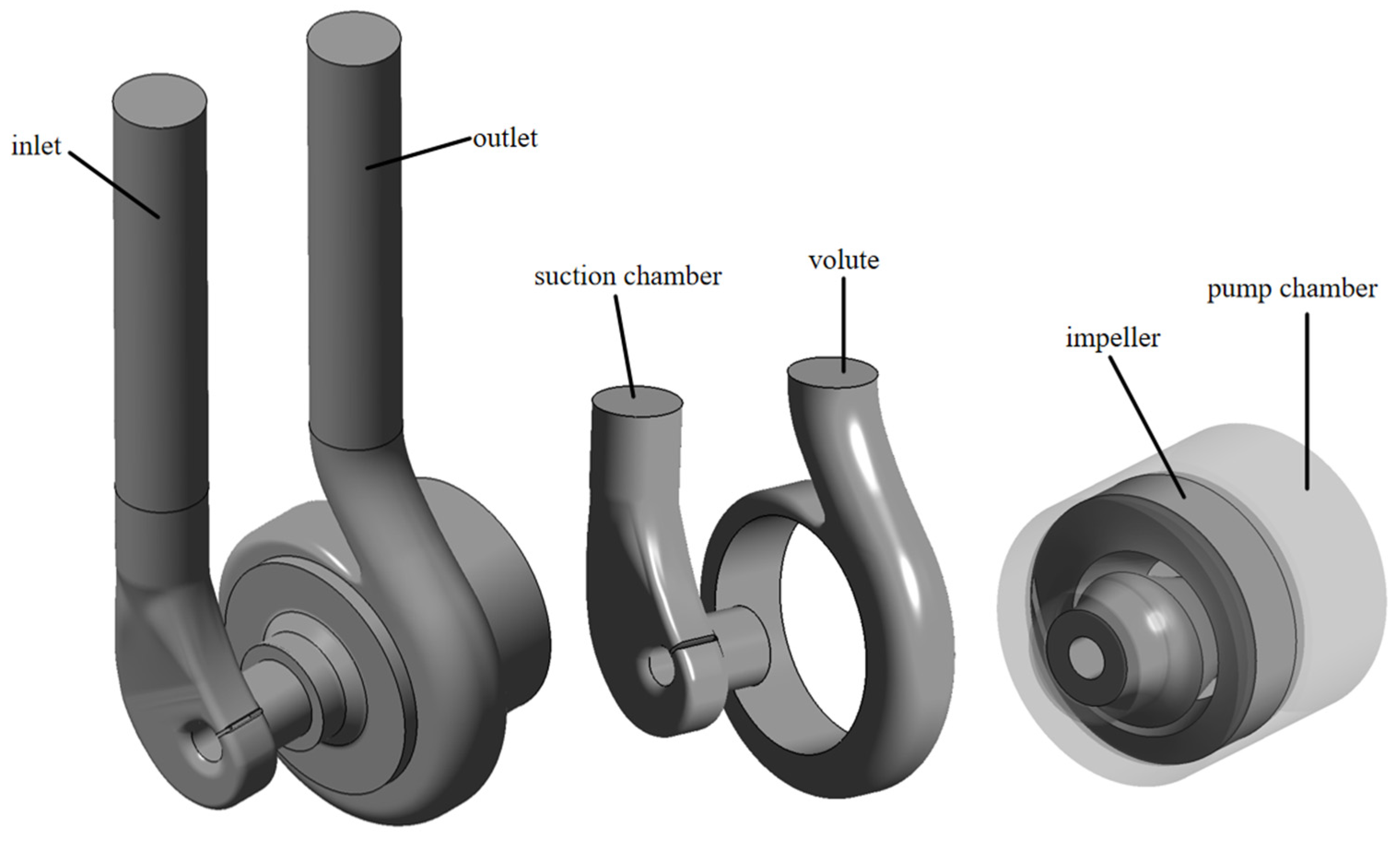
2.1. Calculation Model

The single-blade centrifugal pump also belongs to a kind of centrifugal pump, and its structural form and external characteristics have similar characteristics with ordinary centrifugal pumps. At the same time, the single-blade centrifugal pump has only one blade envelope with a large envelope angle to form a single flow channel. Due to the asymmetry of the structure, a large radial force will be generated during operation, and the non-periodic characteristics are obvious, which is convenient for analysis. Therefore, it becomes the best model to study the transient characteristics of the centrifugal pump in this paper. This paper takes a 2.2 kW single-blade centrifugal pump as the research object, and its design parameters are shown in Table 1. The model components mainly include the inlet and outlet extension section, suction chamber, impeller, front and rear pump chamber, and volute. Figure 1 shows the schematic diagram of the calculation model of the single-blade centrifugal pump.

2.2. Grid Division and Independence Test

The ICEM CFD 18.0 module in ANSYS was utilized to generate grids for the entire circulating pipeline system. High-quality structured grids were employed to enhance the accuracy of the numerical simulation results. To balance computational accuracy and efficiency, varying levels of mesh refinement were applied, particularly in critical regions such as the impeller blade surfaces and the volute tongue near solid walls.
In this paper, the number of cells and nodes on each topology line are adjusted, and a variety of grid number schemes are designed to calculate the grid independence. With the head of a single-blade centrifugal pump as the reference point, when the head curve tends to be stable, it indicates that the numerical simulation results converge. In this paper, the numerical simulation under different grid total is analyzed. The point lift under design condition is taken as the index. The results show that when the number of grids reaches about 2.49 million, the lift is basically unchanged with the increase in the number of grids. Table 2 shows the grid size and number of each part, and the grid has been densified near the wall. Figure 2 shows the grid schematic of the main hydraulic components.

2.3. Flow Control Equation

Due to the fact that the flow inside the centrifugal pump does not consider compressibility, the control equations only require the mass conservation equation and momentum conservation equation [29,30].
(1) Mass conservation equation
The conservation of mass, also called the continuity equation, describes the conservation of fluid at any time, derived from the law of conservation of mass. It can be written as follows:
ρ t + ( ρ u i ) x i = 0
where r represents fluid density; i = 1,2,3 is the repetition index; ui represents the velocity component in the direction of coordinate xi; t is the time.
(2) Momentum conservation equation
The momentum equation is the rate of change in the fluid momentum in the microunit in unit time equal to the sum of various forces acting on the microunit. The specific formula is simplified by Newton’s second law as follows:
( ρ u i ) t + ( ρ u i u j ) x j = p x i + τ i j x j + S m i
where p is the pressure; Smi is the custom source term of the momentum equation, including gravity, the interaction of multiphase flow; τij is the stress tensor and the viscosity on the surface of the particle.

2.4. Numerical Simulation Method

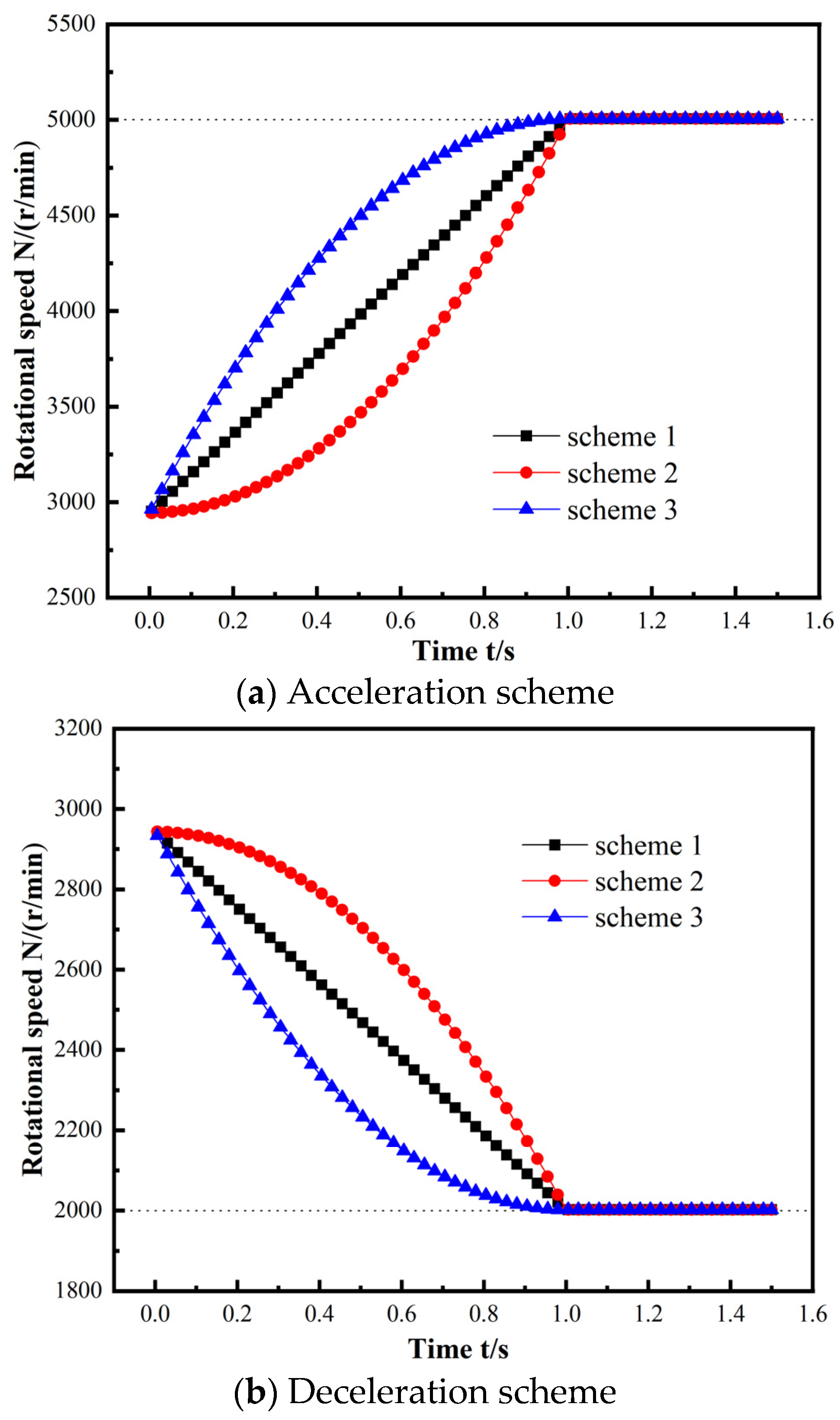
2.4.1. Speed Sudden Change Scheme

In actual operation, the pump speed increase value of each frequency conversion is generally less than 10%, and the growth rate is too large, which is easy to cause the motor overheating, increase the friction loss and bearing loss, resulting in reduced efficiency; similarly, during the deceleration process, the speed drops too much, and the mechanical efficiency and pump efficiency will be greatly reduced, so the actual deceleration value is usually not more than 30%. However, if the speed change is small, it is difficult to observe the characteristic change in the pump with the speed change. In order to highlight the changes in the external characteristics, internal flow field, and radial force of the pump when the speed changes, the increase value of the speed in the numerical simulation is set to exceed 70% of the rated speed (the speed increases to 5000 r/min), and the deceleration value is set to 68% of the original rated speed (the speed decreases to 2000 r/min).
At the same time, according to the similarity theory, the hydraulic performance of the pump is similarly converted, and the rated flow condition in the process of variable speed is obtained. The similar theory of the pump points out that the flow rate of the pump is a linear relationship with the speed, so when the speed changes, the flow rate of the pump will also change accordingly. The expression of the flow rate is as follows [31]:
Q n = n n d × Q d
where n is the real-time speed, nd is the rated speed, Qn is the real-time flow rate, and Qd is the rated flow rate.
By editing CEL expression, different speed changes of single-blade centrifugal pump are realized to meet the needs of unsteady flow calculation research, so as to analyze the transient characteristics of centrifugal pump in the process of speed sudden change. Three acceleration and three deceleration schemes are set up: acceleration Scheme 1 is uniform acceleration, Scheme 2 is acceleration with increasing acceleration, Scheme 3 is acceleration scheme with decreasing acceleration; Deceleration Scheme 1 is uniform deceleration, Deceleration Scheme 2 is continuous acceleration deceleration, and Deceleration Scheme 3 is deceleration with decreasing acceleration.
Figure 3 shows the curve of speed change with time. The speed change time of different schemes is 1 s. In order to more accurately study the change in the flow field in the single-blade centrifugal pump during the speed change process, the model pump will run stably at the final speed for 0.5 s after the frequency conversion speed control is completed until the numerical calculation is completed.

2.4.2. Numerical Scheme

The numerical simulation adopts ANSYS CFX 14.5 and finite volume method to solve the three-dimensional average Reynolds N-S equation and continuous equation. The standard k-ε turbulence model is widely used in numerical simulation of centrifugal pumps. Compared with other models, this model is stable and has good effect [32,33,34,35]. The standard k-ε turbulence model with expandable wall function is adopted, which greatly reduces the computation and has high accuracy.
The coupling relationship between pressure and speed is established by SIMPLEC algorithm. The advection term is set to high resolution, the solid wall is set to non-slip boundary condition, and the wall roughness is set to 50 μm. The mass flow rate is selected as the inlet boundary condition, and the inlet turbulence intensity is set to 5%. According to the experimental results, the pump outlet is set to static pressure. The pump performance curve is obtained by changing the mass flow rate [36]. The pump performance characteristics are simulated by steady-state simulation, and the simulation results are used as the initial value of transient calculation. The time step of the transient calculation is set to 1.701 × 10⁻⁴ s (corresponding to 3° per time step of the rated speed), and the convergence accuracy is set to 10−4.

3. Test Verification
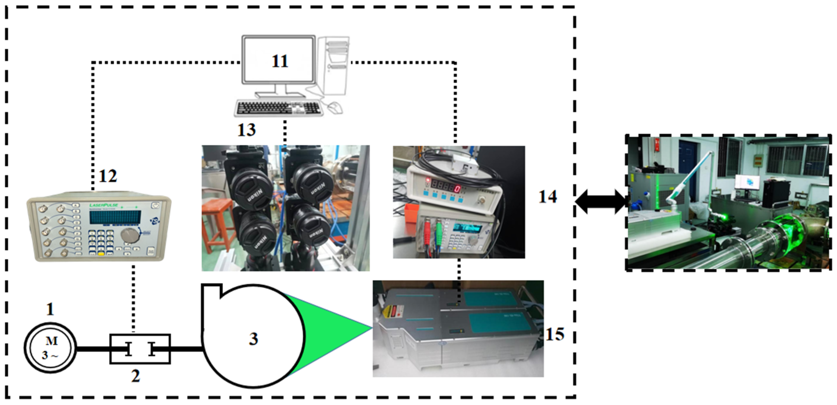
3.1. Test System

The performance test and PIV experiment of the centrifugal pump are conducted on a closed test platform that adheres to the level 2 accuracy standard, ensuring that the maximum allowable error during testing does not exceed 2% of the applied force. Figure 4 shows both the actual photo and the schematic diagram of the test setup. The entire test system consists of three independent modules: the pump installation and operation module, the circulation system module, and the replaceable module. The installation and operation module includes a single-blade centrifugal pump (3), driven by a three-phase AC motor (1) and connected via a coupling (2) to transmit and measure torque. Notably, the coupling is equipped with built-in sensors that monitor torque and speed in real time, transmitting the data to a computer for analysis. The circulation system module comprises lines, flanges (4), pressure transmitters (5) for monitoring inlet and outlet pressures, flexible rubber connectors (6), solenoid valves for precise flow regulation (7), large water tanks (8), and electromagnetic flowmeters (9) for accurate flow measurement. The data from the pressure transmitters and electromagnetic flowmeters are sent directly to the computer, which also controls the solenoid valves to ensure the accuracy of the test. The replaceable modules can be customized and swapped based on specific experimental requirements. During the performance test, the data collector (10) and the terminal computer (11) are integrated into the module shown in Figure 4. The data collector converts the acquired information into a signal format and transmits it to the computer, where the experimenter can adjust test parameters such as flow.
Figure 5 shows the actual product of the model pump used in the test. The basic parameters of the test pump are basically consistent with those of the model pump used for numerical simulation. The outer layer of the shell is transparent plexiglass, which is convenient to observe the flow field in the pump.
For safety and equipment-bearing capacity considerations, PIV flow field tests were conducted to observe the flow field changes in the pump under a uniform deceleration scheme, with the experimental deceleration changes aligning with the numerical simulation’s Deceleration Scheme 1. During the test, a CCD camera captured 50 tracer particle images per second, and one out of every 10 images was selected for analysis. After post-processing, Tecplot 2023 was used to generate velocity streamline distribution maps at different time intervals, and the velocity fields obtained from the test were compared and analyzed.
The standby module is equipped with a dedicated PIV system, including a synchronizer (12), CCD camera (13), external trigger synchronization system (14), Vlite-Hi-100 pulsed laser made by Beamtech Optronics Co., Ltd., Beijing, China (15), and auxiliary equipment such as power supply and cooling system, as shown in Figure 6.

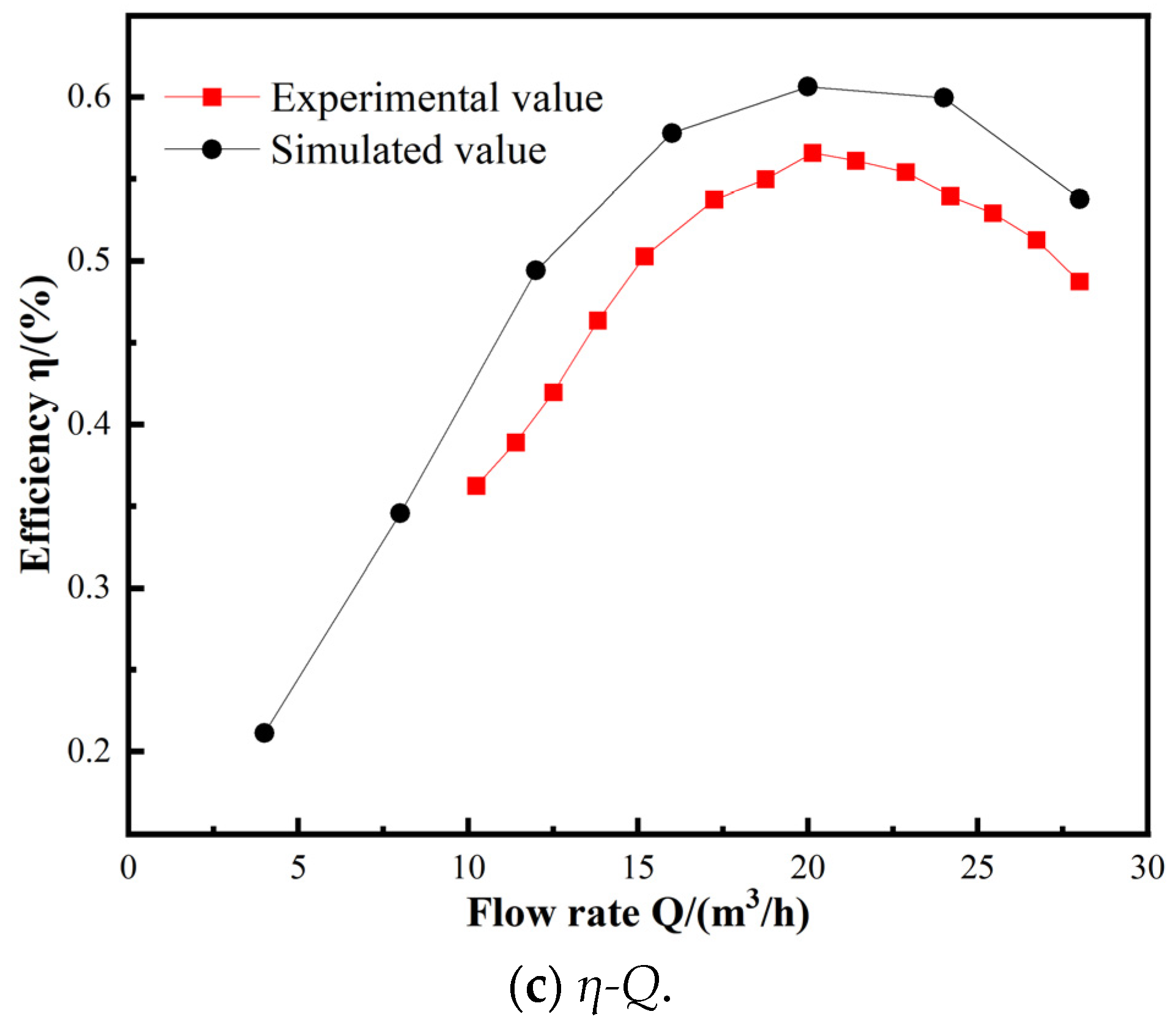
3.2. Test Results of External Characteristics

Figure 7 presents the measured data for the external characteristics of the model pump. The overall trend of the experimental data is consistent with the results from the numerical simulation. As the flow rate increases, the test head value for the model pump gradually decreases, consistently remaining lower than the simulation results. This discrepancy is primarily attributed to factors such as volume loss, mechanical losses, and hydraulic losses caused by friction in the pipeline wall during pump operation. However, under rated flow conditions, the error remains within an acceptable range, not exceeding 5%. According to the work of K.W. Cheah et al. [37], such discrepancies are considered acceptable in numerical simulations of centrifugal pumps. The efficiency curve follows a parabolic shape, with maximum efficiency occurring at approximately 50% of the design conditions. The shaft power curve increases linearly, showing some deviation from the numerical simulation, but the overall trend remains similar. Overall, the reliability of the external characteristic test is validated. The external characteristics test is compared with the results of numerical simulations at rated speed. The boundary conditions used in the numerical simulation process are based on the external characteristic test, thereby confirming the reliability of the numerical simulation. As reported by K.W. Cheah et al. [37], such discrepancies are acceptable in centrifugal pump numerical simulations, and their accuracy aligns with the predictions made by Ye [38]. Furthermore, the numerical simulation of the variable-speed process has been significantly improved compared to current applications of the variable speed range, with the uniform variable speed also being validated by the test using a frequency converter. This analysis of the impact of a large variable speed range broadens the practical application of the pump and ensures its reliability and safety under variable speed regulation.

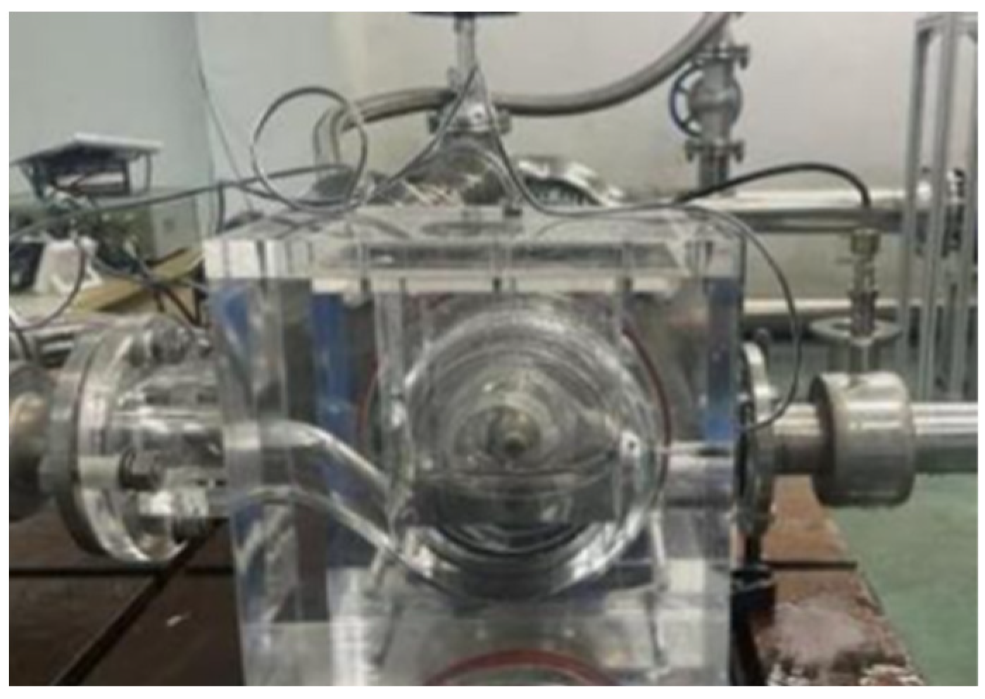
3.3. PIV Test Results

Figure 8 presents a comparison of the flow field distribution obtained from the PIV test and numerical simulation for the single-blade centrifugal pump under the uniform deceleration scheme. Due to the vertical laser positioning from the top of the model pump, the hub obstructs the lower region, preventing the laser from passing through and causing the particles below the model pump to be uncaptured. This limitation impacts the completeness of the flow field data in this region. Consequently, the experiment primarily focuses on analyzing the flow field in the areas where the flow is captured and suitable for further study.
It can be observed that the streamline trends in both the test and numerical simulation are largely consistent, with corresponding high-speed and low-speed regions in each case. The flow within the impeller exhibits characteristics of spiral propulsion, and the velocity decreases rapidly as deceleration time increases. Overall, the PIV test aligns well with the numerical simulation, demonstrating high accuracy. Analysis of the flow field under the uniform deceleration scheme leads to the following conclusions: the streamlines are smooth, indicating a relatively stable flow field. This stability ensures that the centrifugal pump can operate steadily during the speed variation process.

4. Results and Discussion

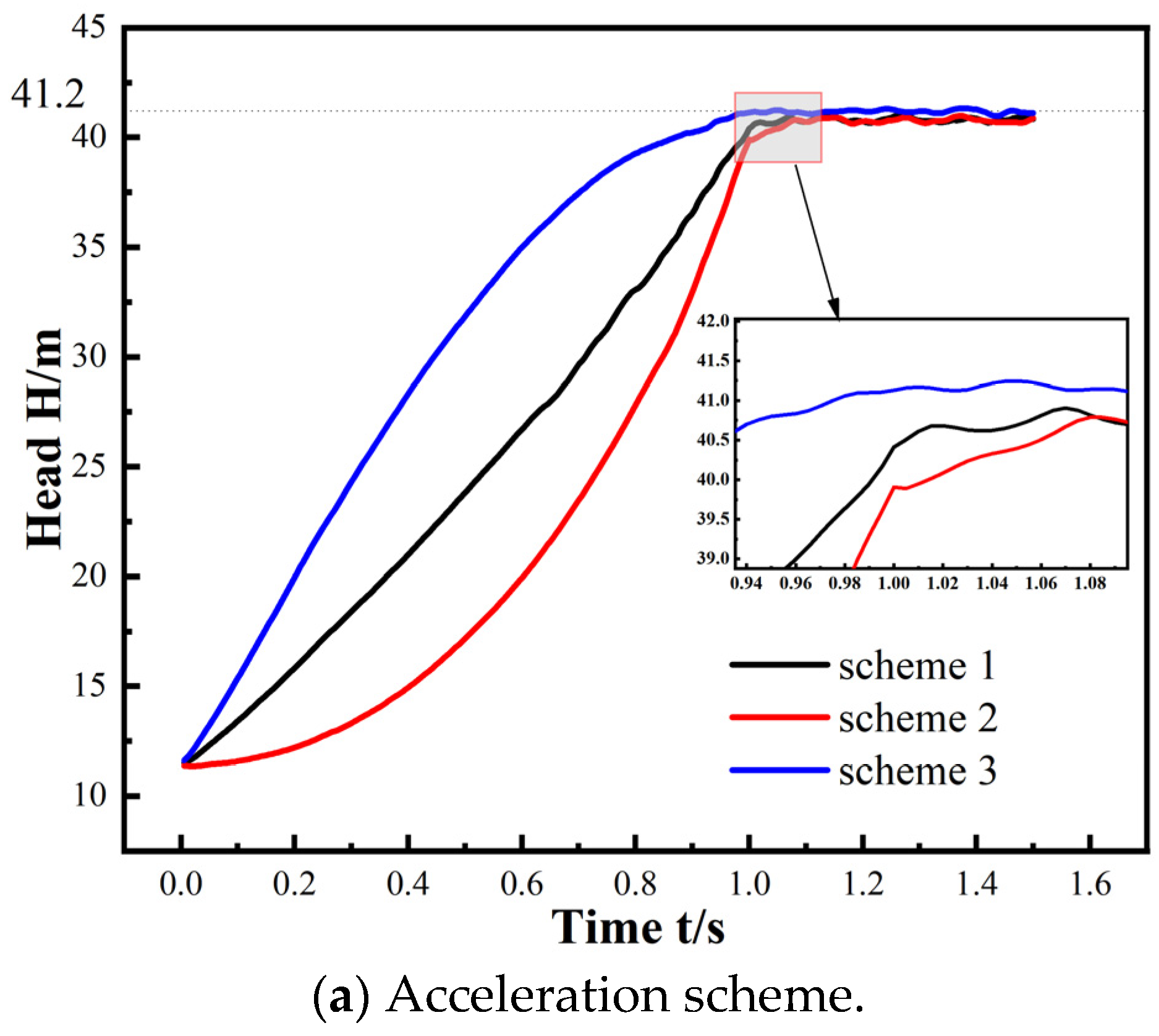
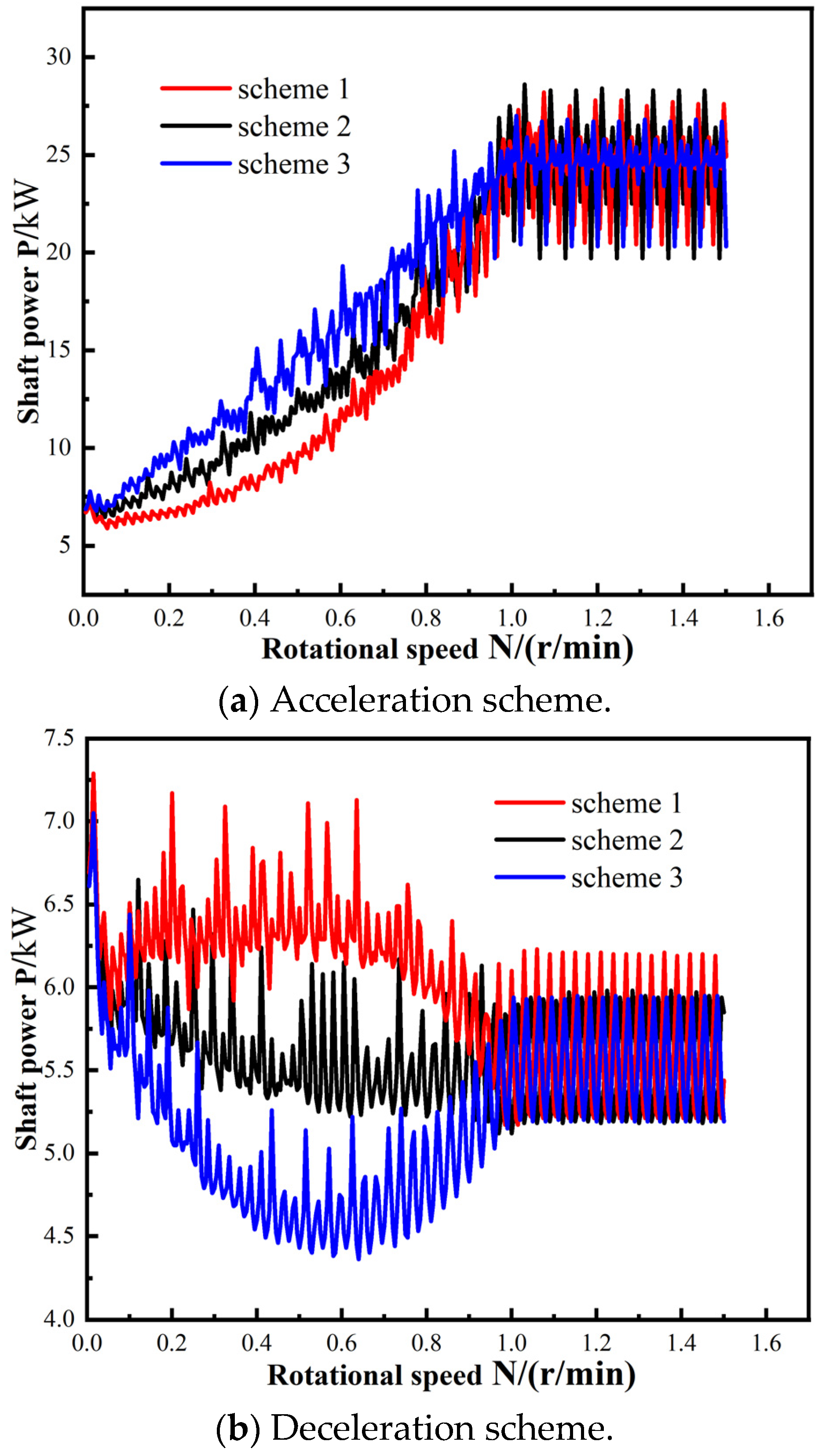
4.1. Transient External Characteristics

The transient characteristics of the head and power of the single-blade centrifugal pump are quite pronounced during sudden speed changes, and the patterns of these changes are not clearly defined. To minimize the impact of such speed changes on the pump and pipeline system and to improve system reliability, selecting an appropriate variable speed scheme is crucial. Figure 9 shows the real-time head change curve obtained through transient calculations under different speed-change schemes. As shown in Figure 9a, the head variation generally follows the same trend as the speed variation. As speed increases, the head of the centrifugal pump also increases; when the pump reaches its rated speed, the head also reaches its maximum, maintaining synchronization between the pump head and speed. After 1 s of acceleration, all three schemes achieve the target head value, and the difference between the schemes does not affect the steady-state head of the centrifugal pump. The centrifugal pump reaches the set head under all three schemes. Upon zooming in at 1 s, it is evident that acceleration Scheme 3 (decreasing acceleration) reaches the target head first. Furthermore, by analyzing the head fluctuations after the speed change in the three acceleration schemes, it is observed that acceleration Scheme 3 better maintains head stability after the speed change, with minimal impact on the system. This suggests that the acceleration scheme with a constantly decreasing acceleration offers superior speed regulation performance during the acceleration process. Figure 9b presents the transient head for the three deceleration schemes, and the change trends of the heads are generally consistent with the speed trends. A closer inspection of the magnified head chart reveals that the head fluctuates significantly during the initial variable speed phase, with Deceleration Scheme 2 (increasing acceleration) showing the most intense fluctuations. In contrast, Scheme 3 (decreasing acceleration) is the most stable, exhibiting the least head fluctuation. This indicates that the speed-change scheme with decreasing acceleration is the most effective in achieving a smooth speed change and maintaining stability after the speed change, which is beneficial for the stability of the pump during the sudden speed change process.
Figure 10 illustrates the variation in shaft power over time during the variable speed process. As depicted in Figure 10a, the overall trend of shaft power growth during acceleration is consistent across all three schemes. However, due to the influence of unsteady dynamic and static interference within the centrifugal pump during variable speed operation, the shaft power exhibits noticeable pulsation characteristics. Among the three schemes, Scheme 3 displays the highest overall shaft power, while Scheme 2 demonstrates the lowest shaft power with minimal fluctuations. This discrepancy is primarily attributed to Scheme 3 achieving the highest speed, which results in a rapid increase in velocity, requiring the centrifugal pump to overcome the rapidly escalating fluid inertia force. In the initial stages of acceleration, shaft power fluctuations are minimal. However, after 0.4 s of acceleration in Scheme 3, the fluctuation range of the shaft power significantly increases, accompanied by more pronounced variations in external characteristic parameters. Overall, Scheme 2 not only maintains the lowest shaft power but also exhibits the least fluctuation. Consequently, from the perspective of shaft power, Scheme 2 is preferable as it promotes greater stability and safety during the centrifugal pump’s sudden speed change process.
Figure 10b illustrates the variation in shaft power over time under the three deceleration schemes. As the speed decreases, the flow rate of the centrifugal pump declines sharply, resulting in a significant initial decrease in shaft power. During the deceleration process, the amplitude of shaft power fluctuations gradually increases, primarily due to intensified flow impacts within the pump and unsteady dynamic and static interference. Scheme 3 exhibits the fastest decline in shaft power and the most pronounced fluctuations initially, as it features the largest initial acceleration and a rapid reduction in speed. After 0.6 s, the shaft power in Scheme 3 begins to rise, mainly because the pump flow, deviating from the rated condition, becomes more complex, leading to increased flow disturbances within the pump. Scheme 1 experiences the most gradual decline in shaft power, with the smoothest transition at the end of the deceleration phase. In Scheme 2, shaft power is the highest during deceleration, with a noticeable increase in shaft power during the initial deceleration phase. Overall, Scheme 3 achieves the lowest shaft power throughout the variable speed process. After deceleration, when the pump reaches stable operation, the shaft power in all three schemes fluctuates periodically, with Scheme 2 exhibiting the most pronounced fluctuations.

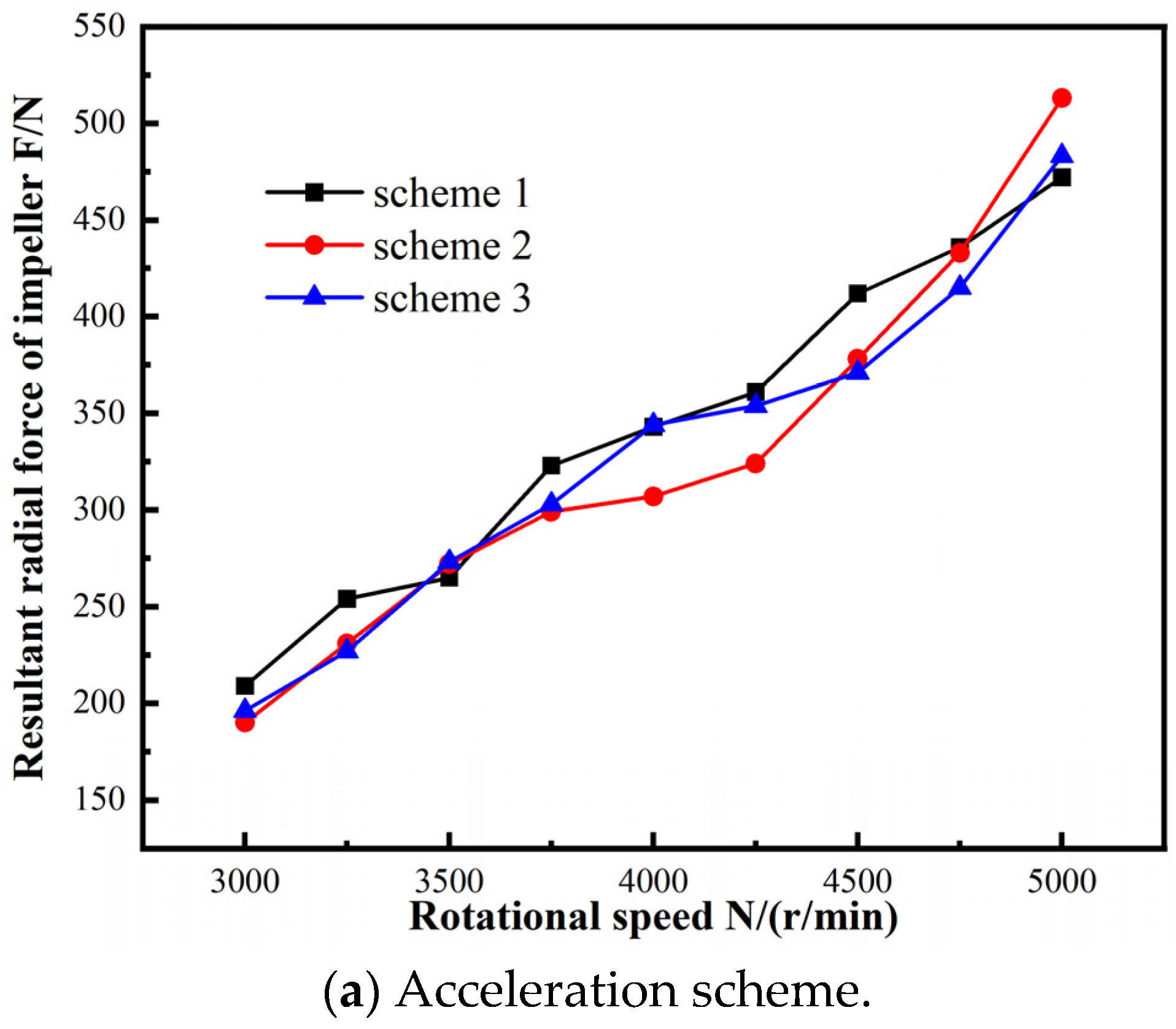
4.2. Radial Force on Impeller During Variable Speed

The single-blade centrifugal pump features a single blade with a large envelope angle, and the impeller has a circular asymmetric structure. This design inevitably results in significant radial forces during operation. Additionally, due to inertial effects and strong unsteady dynamic and static interference during the variable speed process, the liquid flowing out of the impeller collides forcefully with the pressure chamber. This collision causes the internal flow within the pump to exhibit a circular non-uniform distribution, which further contributes to the radial force. To study the variation in transient radial force in the single-blade centrifugal pump during the variable speed process, unsteady numerical simulations were conducted. The direct calculation method was used to obtain the radial force on the impeller by integrating the pressure on the impeller’s flow surface.
The radial force of the impeller mainly comes from the pressure and viscous force of the fluid on the impeller. The ANSYS CFX 14.5 was used to edit the CEL calculation formula to calculate the radial pressure and viscous force of the grid nodes on the interface of the impeller and the volute, as well as the pressure separation force at the wall of the impeller and the front and rear cover plate, and the resultant force was calculated by the synthesis theorem of the force. The direct calculation method of CEL expression is as follows.
Force in the X direction:
Fx = force_x()@Impeller_Front_Shroud+force_x()Impeller_Back_Shroud
+force_x()@Impeller_Blades+force_x()@Interface1+force_x()@Interface2
Force in the Y direction:
Fy = force_y()@Impeller_Front_Shroud+force_y()Impeller_Back_Shroud
+force_y()@Impeller_Blades+force_y()@Interface1+force_y()@Interface2
Joint force of the radial force:
F = (force_x^2 + force_y^2)^(1/2)
As shown in Figure 11a, with an increase in rotational speed, the radial force on the impeller rises rapidly, although it does not follow the same trend as the rotational speed. The radial force values across different rotational speeds for each scheme show little variation, with Scheme 1 exhibiting the most stable overall radial force. Before 4500 rpm, Scheme 2 has the smallest radial force. However, after 4500 rpm, the acceleration in Scheme 2 increases, causing a significant rise in its radial force, which becomes the highest at 5000 rpm. This indicates that rotational acceleration has a notable impact on the radial force.
As shown in Figure 11b, the radial force under three deceleration schemes at different speeds during the deceleration process is presented. It can be observed that the radial force decreases significantly as the speed reduces, with the radial force changing most steadily under different speeds and approximately linearly as the speed decreases. Scheme 3 exhibits the largest radial force at the initial deceleration stage, coinciding with its highest initial acceleration. After decelerating to 2600 rpm, the acceleration in Scheme 3 becomes lower than that in Scheme 2, and the radial force in Scheme 2 becomes the largest. Once the speed drops to 2100 rpm, the radial forces of the three schemes converge and become consistent.
As described in Section 2.4.1 above, in order to highlight the change in the radial force of the pump when the speed changes, and avoid an excessive growth rate causing overheating of the motor and reducing efficiency, the speed increase value in the numerical simulation is set to exceed 70% (speed increased to 5000 r/min) of the rated speed (2940 r/min). In this paper, the radial forces under acceleration at three different speeds were selected, namely, the initial value of 2940 r/min, the intermediate value of 4000 r/min, and the final value of 5000 r/min during the acceleration process, and the radial forces borne by the impeller during the constant speed process were compared, as shown in Table 3.
By comparing the radial force at 2940 rpm, 4000 rpm, and 5000 rpm, it can be observed that the radial force under the three acceleration schemes is greater than the radial force at the corresponding steady-state speeds. This is primarily due to the impact of rotational acceleration on the inlet and outlet of the impeller blades and the volute. Additionally, the distribution of the flow field in the circumferential direction becomes more uneven during acceleration, contributing to the increase in radial force. The variation in radial force under different rotational speeds shown by this result is similar to the work of Zhou et al. [17].

4.3. Internal Flow Field Characteristics in Variable Speed Process

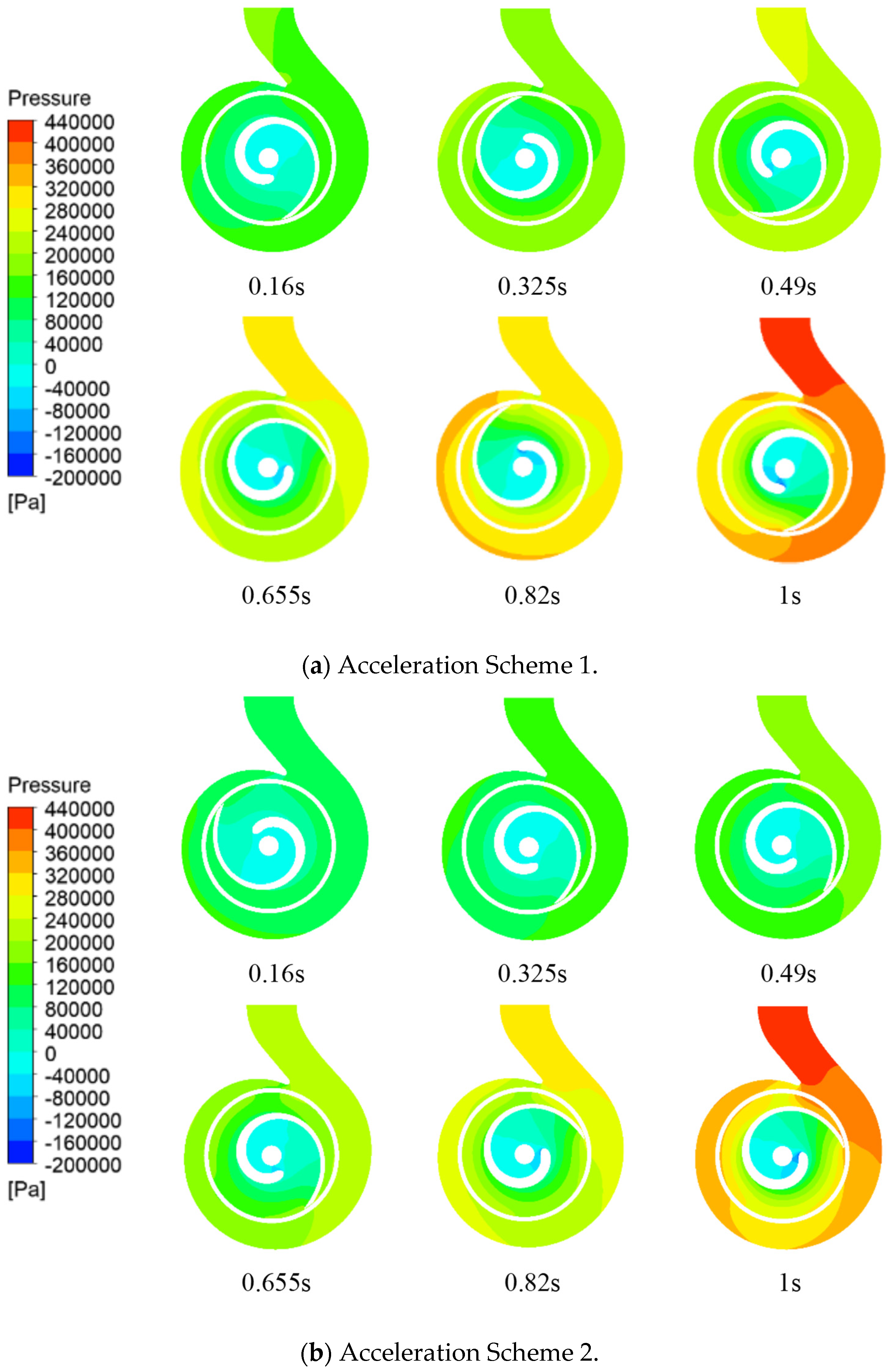
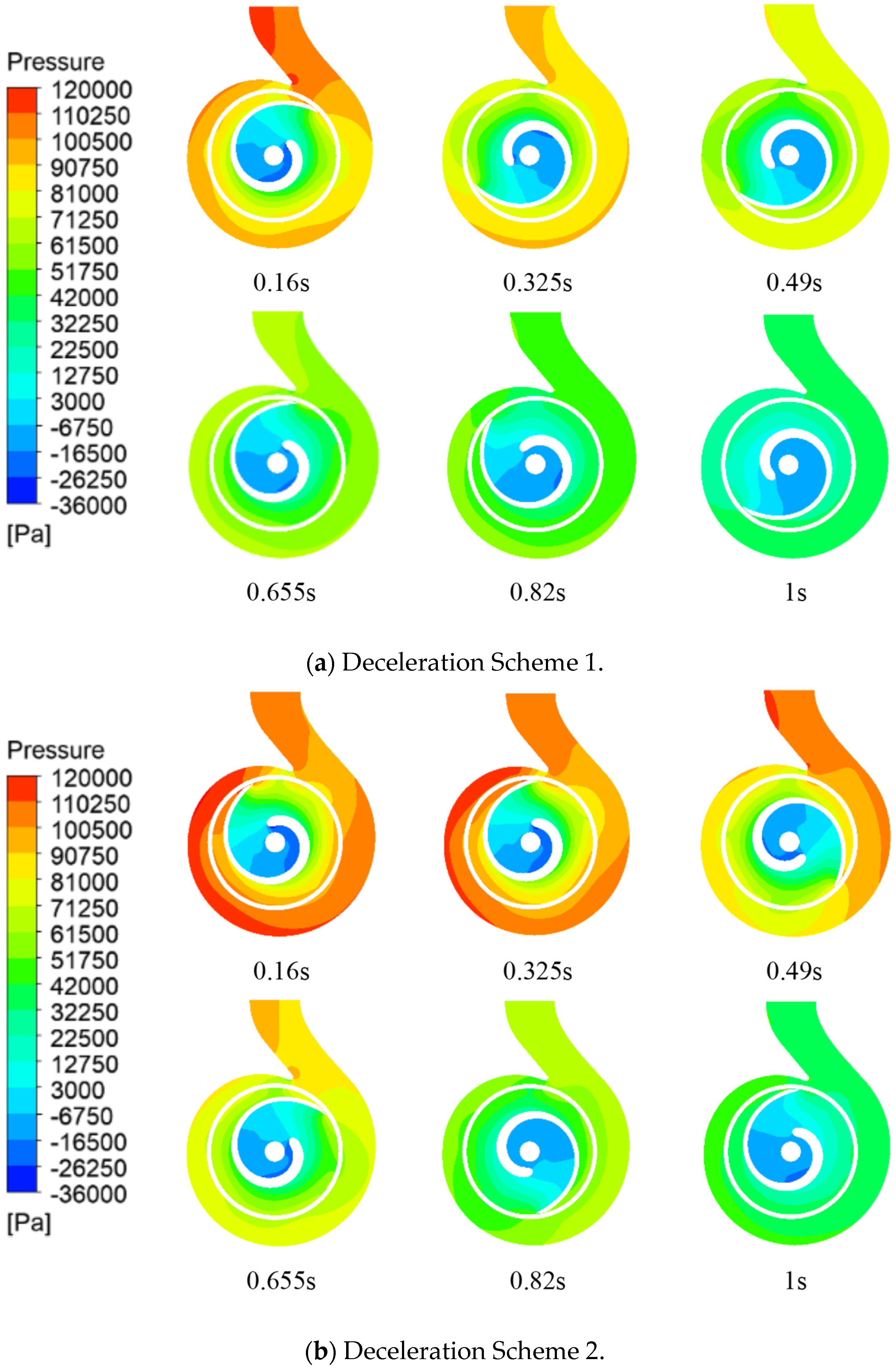
4.3.1. Pressure Field Distribution

To investigate the transient external characteristics of the pump and the causes of radial force during the variable speed process, the transient pressure field of the pump was analyzed. Figure 12 illustrates the mid-section pressure distribution of the single-blade centrifugal pump at various times under different acceleration schemes. Six distinct time intervals (0.16 s, 0.325 s, 0.49 s, 0.655 s, 0.82 s, and 1 s) were selected to examine the pressure within the impeller volute. Under all three acceleration schemes, a localized low-pressure area appears near the back of the blade inlet. As speed increases, this low-pressure region expands, and negative pressure develops at the inlet edge. This phenomenon is primarily attributed to the significant impact at the inlet caused by the changing speed, with the impact intensifying as the speed increases. The static pressure gradually rises from the leading edge to the trailing edge of the blade, reaching its maximum at the volute outlet. The pressure on the pressure surface of the blade exceeds that on the suction surface at corresponding radii. As speed increases, the instantaneous pressure within the pump also rises. Among the three schemes, Scheme 3 exhibits the most rapid increase in pressure.
Figure 13 shows the mid-section pressure distribution of the single-blade centrifugal pump at different times under various deceleration schemes. As speed decreases under the three deceleration schemes, the pressure within the impeller volute gradually decreases, and the low-pressure area at the center of the impeller enlarges, particularly in the early stages of speed change. During the initial phase of deceleration (0.16–0.49 s), the pressure within the flow channel of the centrifugal pump is highest, with a clear pressure distribution gradient, and a distinct high-pressure area remains within the volute. Throughout the speed change process, the pressure distribution in the pump under Scheme 2 is the most uneven, with the high-pressure and low-pressure zones being the most pronounced and enduring, which is detrimental to the stable operation of the centrifugal pump. In contrast, deceleration Scheme 3 exhibits the lowest pressure values, the smallest pressure gradient, the most uniform pressure distribution, and the smallest local low-pressure area at the center of the impeller throughout the deceleration process. At 0.16 s, the pressure at the septal tongue is higher, while the main part of the impeller is influenced by strong flow impact, creating an evident high-pressure area.

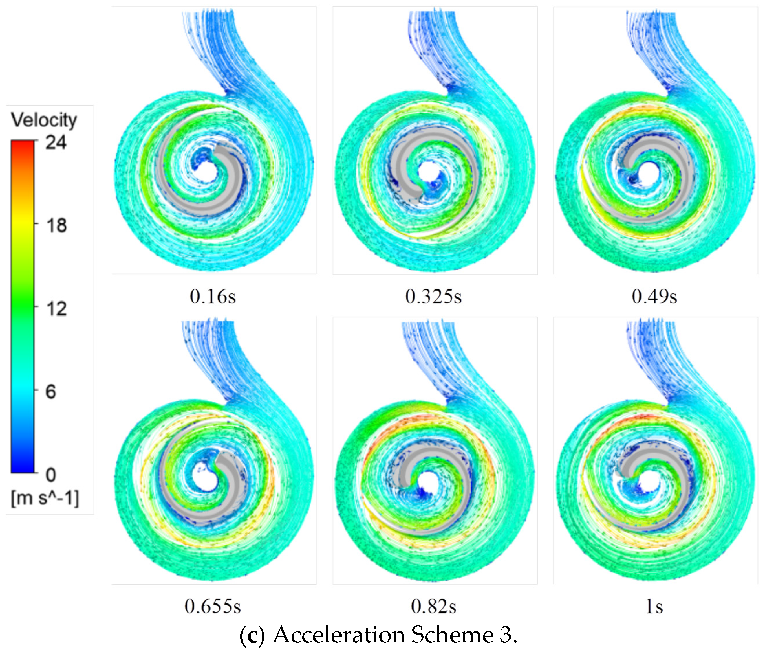
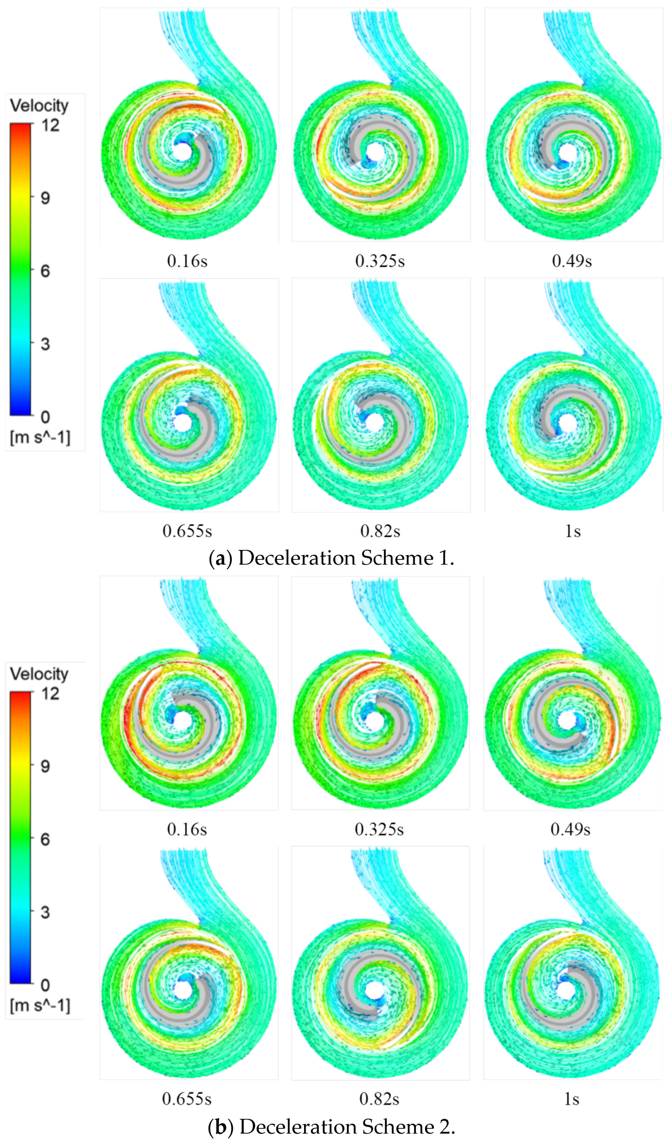
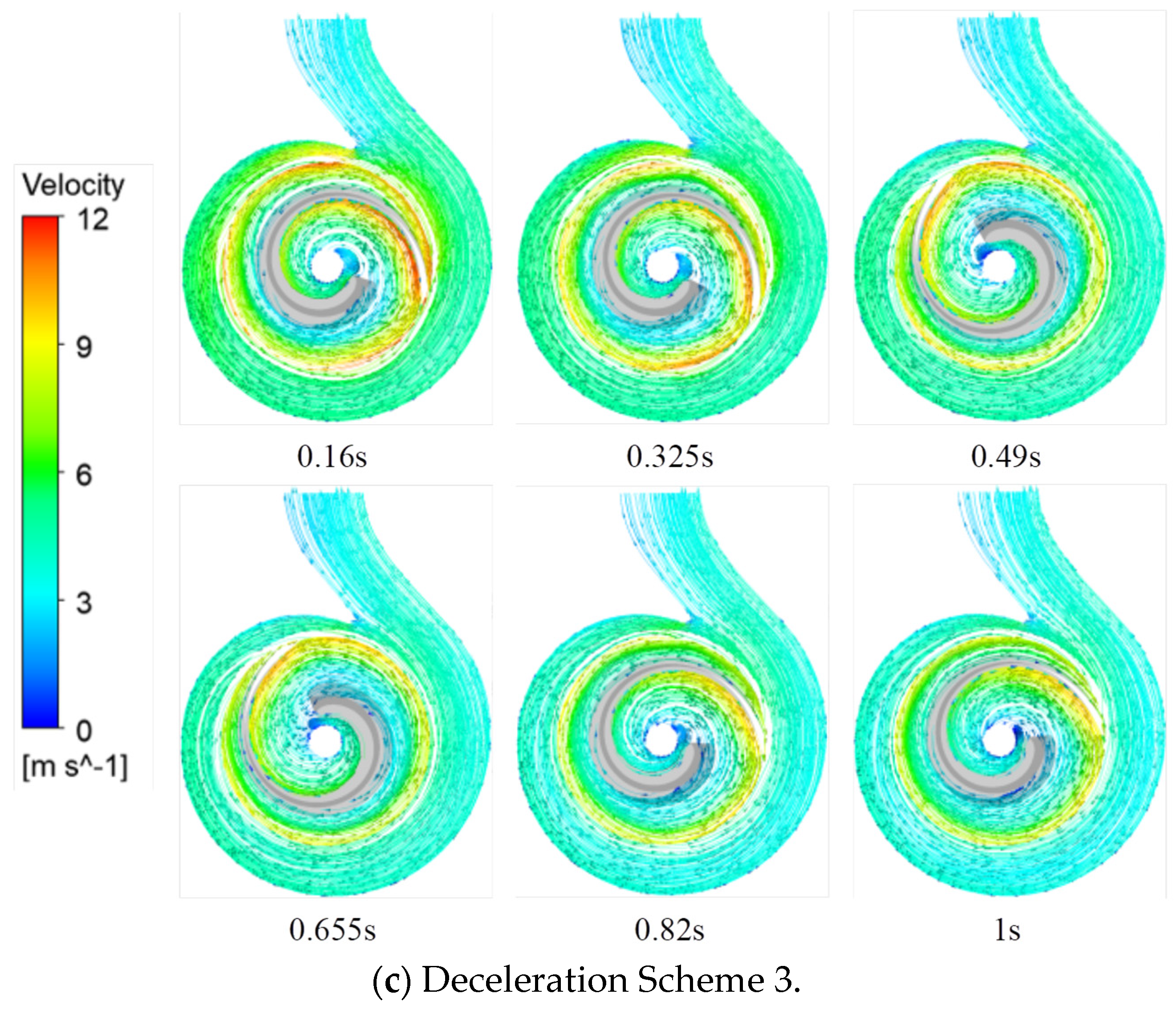
4.3.2. Flow Field Distribution

Figure 14 shows the mid-section streamline distribution and velocity vector diagram of the single-blade centrifugal pump at different times under various acceleration schemes. The same six times are selected for analysis in this section. As shown in the figure, at the initial acceleration of 0.16 s, there is a lag in the speed increase, and the speed changes very little, resulting in relatively stable streamline distribution within the pump. At 0.325 s, flow separation occurs on the working face of the impeller in Schemes 1 and 3 due to their larger initial accelerations and higher rotational speeds, which cause instability in the fluid flow within the pump. Although the speed is the same across all three schemes at this point, the large acceleration and greater deviation from the rated speed in these two schemes lead to significant variations in the speed within the pump. As a result, flow separation is more pronounced, and the vortex structure expands. After 1 s, when the speed becomes constant, the streamlines within the pump gradually stabilize under all three schemes. However, due to the high rotational speed, the pump body experiences more vibration, causing the streamline distribution to remain less stable than at the rated speed. This analysis highlights that speed is a critical factor affecting the flow field in the pump—at higher speeds, the flow field becomes more chaotic, and flow separation becomes more noticeable.
Figure 15 shows the mid-section streamline distribution and velocity vector diagram of the single-blade centrifugal pump at different times under various deceleration schemes. The figure reveals that during the deceleration process, there is a low-speed zone at the inlet of the impeller, with the speed gradually increasing from the leading edge to the trailing edge of the blade. Additionally, the speed on the working surface of the blade is lower than that on the back. As the speed decreases, the pressure difference between the blade face and the back gradually diminishes, and the speed difference between the two sides also decreases. Comparing the three deceleration schemes, it can be observed that in Scheme 2, the speed at the back of the impeller and the exit of the impeller before 0.655 s is higher than in the other two schemes. This is because Scheme 2 has a smaller initial acceleration, causing the speed to change more gradually, and the flow rate in the pump before 0.655 s is higher compared to the other two schemes. In Scheme 3, the streamlines within the impeller before 0.325 s are relatively chaotic. This is due to the large initial acceleration, which causes a rapid increase in the pressure difference between the two sides of the impeller, leading to instability in the fluid flow within the pump and resulting in disturbed streamlines. After 0.655 s, as the speed in the pump decreases, the streamline distribution across all three schemes becomes more consistent, with deceleration completed by 1 s. Following this, all three schemes operate at the same speed, and the streamline distribution remains relatively stable. Overall, the most stable streamlines throughout the entire deceleration process are observed when the acceleration is kept constant.

5. Conclusions

In this study, the transient external performance, internal flow patterns, and radial force characteristics of a single-blade centrifugal pump were investigated using numerical simulations, performance tests, and PIV experiments. The key findings and conclusions drawn from this research are summarized as follows:
(1) External characteristic tests, PIV experiments, steady-state, and transient numerical simulations were conducted. The numerical pump performance closely aligns with the results obtained from the external characteristic tests. As the flow rate increases, the pump head decreases gradually, remaining consistently lower than the simulation results. Under rated flow conditions, the calculation error does not exceed 5%. In the PIV experiments, the observed streamline trends are largely consistent with those predicted by the numerical simulations.
(2) Three speed-change schemes were evaluated through transient simulations. The decreasing acceleration scheme (Scheme 3) proved to be the most effective in achieving and maintaining stability after the speed change. In contrast, the increasing acceleration scheme (Scheme 2) exhibited minimal fluctuations in shaft power. Scheme 2 also demonstrated the most uniform pressure distribution, while Scheme 3 exhibited the lowest pressure with an even distribution following the speed change.
(3) The impeller radial force under the three acceleration schemes at varying speeds was found to be greater than the radial force at the corresponding steady-state speed. The gradually decreasing acceleration scheme improved operational smoothness, reduced radial force fluctuations, and ensured more uniform pressure distribution. Scheme 2 was optimal for controlling shaft power stability, offering valuable insights for the design of centrifugal pumps under variable speed conditions.

Author Contributions

Methodology, L.T.; Software, J.N.; Validation, W.S., M.Z. and S.G.; Formal analysis, Y.Y.; Investigation, Z.Z.; Data curation, T.W.; Writing—original draft, J.N.; Writing—review & editing, Y.Y.; Supervision, H.L.; Funding acquisition, Y.Y. All authors have read and agreed to the published version of the manuscript.

Funding

This research was funded by the National Natural Science Foundation of China (Grant Nos. 52109106, 52409122, and 12272187), the Cooperative Research Project of the Ministry of Education’s “Chunhui Program” (Grant No. HZKY20220117), the Natural Science Foundation of Jiangsu Province (Grant Nos. BK20220587 and BK20220609), Open Research Subject of Key Laboratory of Fluid Machinery and Engineering (Xihua University), and Sichuan Province (Grant Nos. LTDL-2022008 and LTDL-2024005).

Data Availability Statement

The data that support the findings of this study are available from the corresponding author upon reasonable request.

Conflicts of Interest

Author Miaomiao Zhao was employed by the company Suzhou Water Conservancy Design and Research Co., Ltd. The remaining authors declare that the research was conducted in the absence of any commercial or financial relationships that could be construed as a potential conflict of interest.

References

  1. Lin, Y.; Li, X.; Zhu, Z.; Wang, X.; Lin, T.; Cao, H. An energy consumption improvement method for centrifugal pump based on bionic optimization of blade trailing edge. Energy 2022, 246, 123323. [Google Scholar] [CrossRef]
  2. Luo, W. Status Analysis of agricultural irrigation pumping station (group) and energy-saving countermeasures. Drain. Irrig. Mach. 1988, 26–29. [Google Scholar]
  3. Sun, Z.; Zhou, Y.; Chen, Y.; Huang, X.; Li, D. Research on hydraulic performance of vertical outlet channel in large submersible pump station. China Water Supply Drain. 2018, 34, 1–5. [Google Scholar]
  4. Shankar, V.K.A.; Umashankar, S.; Paramasivam, S.; Hanigovszki, N. A comprehensive review on energy efficiency enhancement initiatives in centrifugal pumping system. Appl. Energy 2016, 181, 495–513. [Google Scholar] [CrossRef]
  5. Tsukamoto, H.; Ohashi, H. Transient characteristics of a centrifugal pump during starting period. J. Fluids Eng. 1982, 104, 6–13. [Google Scholar] [CrossRef]
  6. Tsukamoto, H.; Yoneda, H.; Sagara, K. The response of a centrifugal pump to fluctuating rotational speed. J. Fluids Eng. 1995, 117, 479–484. [Google Scholar] [CrossRef]
  7. Lefebvre, R.J.; Barker, W.P. Centrifugal pump performance during transient operation. J. Fluids Eng. 1995, 117, 123–128. [Google Scholar] [CrossRef]
  8. Li, W.; Huang, Y.; Ji, L.; Ma, L.; Agarwal, R.K.; Awais, M. Prediction model for energy conversion characteristics during transient processes in a mixed-flow pump. Energy 2023, 271, 127082. [Google Scholar] [CrossRef]
  9. Thanapandi, P.; Prasad, R. Centrifugal pump transient characteristics and analysis using the method of characteristics. Int. J. Mech. Sci. 1995, 37, 77–89. [Google Scholar] [CrossRef]
  10. Thanapandi, P.; Prasad, R. A Qoptuasi-steady performance prediction model for dynamic characteristics of a volute pump. Proceeding Inst. Mech. Eng. Part A J. Power Energy 1994, 208, 47–58. [Google Scholar] [CrossRef]
  11. Wu, D.; Jiao, L.; Wang, L. Experimental study on transient hydraulic performance of centrifugal pump under different starting acceleration. J. Eng. Thermophys. 2008, 29, 62–64. [Google Scholar]
  12. Hu, Z.; Wu, D.; Wang, L. Transient Hydraulic characteristics of centrifugal Pump during rapid start-up process—External characteristics study. J. Zhejiang Univ. Eng. Ed. 2005, 39, 605–608. [Google Scholar]
  13. Zhang, S.; Wu, D. Development of transient performance Test System for centrifugal Pump during rapid start-up. Acta Metrol. Sin. 2005, 26, 159–162. [Google Scholar]
  14. Ping, S.; Wu, D.; Wang, L. Transient Effect Analysis of Centrifugal Pump during rapid opening. J. Zhejiang Univ. (Eng. Technol.) 2007, 41, 112–115. [Google Scholar]
  15. Zhang, Y.; Zhu, Z.; Cui, B.; Li, Y.; Dou, H. Experimental study on rapid start-up process of centrifugal pump. J. Eng. Thermophys. 2013, 34, 2056–2060. [Google Scholar]
  16. Brennen, C.E.; Acosta, A.J. Fluid-induced rotordynamic forces and instabilities. Struct. Control Health Monit. 2006, 13, 10–26. [Google Scholar] [CrossRef]
  17. Zhou, W.; Yu, D.; Wang, Y.; Shi, J.; Gan, B. Research on the fluid-induced excitation characteristics of the centrifugal pump considering the compound whirl effect. Facta Univ. Ser. Mech. Eng. 2023, 21, 223–238. [Google Scholar] [CrossRef]
  18. Baun, D.O. Effect of Relative Impeller-to-Volute Position on Hydraulic Efficiency and Static Radial Force Distribution in a Circular Volute Centrifugal Pump. J. Fluids Eng. 2000, 122, 598–605. [Google Scholar] [CrossRef]
  19. Boehning, F.; Timms, D.L.; Amaral, F.; Oliveira, L.; Graefe, R.; Hsu, P.; Schmitz-Rode, T.; Steinseifer, U. Evaluation of Hydraulic Radial Forces on the Impeller by the Volute in a Centrifugal Rotary Blood Pump. Artif. Organs 2011, 35, 818–825. [Google Scholar] [CrossRef]
  20. Shadab, M.; Karimipour, M.; Najafi, A.F.; Paydar, R.; Nourbakhsh, S.A. Effect of impeller shroud trimming on the hydraulic performance of centrifugal pumps with low and medium specific speeds. Eng. Appl. Comput. Fluid Mech. 2022, 16, 514–535. [Google Scholar] [CrossRef]
  21. Benra, F.K. Numerical and experimental investigation on the flow induced oscillations of a single-blade pump impeller. J. Fluids Eng. 2006, 128, 783–793. [Google Scholar] [CrossRef]
  22. Nishi, Y.; Fukutomi, J. Effect of impeller outlet width on radial thrust of single-blade centrifugal pump with a helical spiral suction flow channel. Turbomachinery 2011, 39, 47–56. [Google Scholar]
  23. Nishi, Y.; Fukutomi, J. Effect of blade outlet angle on unsteady hydrodynamic force of closed-type centrifugal pump with single blade. Int. J. Rotating Mach. 2014, 4, 1–16. [Google Scholar] [CrossRef]
  24. Jiang, W.; Chen, D.; Wang, Y.; Zhu, X.; Li, G. Numerical Simulation Study on the influence of half-height guide vane on the excited force of centrifugal pump. J. Vib. Shock 2019, 38, 20–27. [Google Scholar]
  25. Zhang, J.; Ye, L.; Yuan, S.; Yuan, Y. Effect of shunt blade on Vibration Force Characteristics of centrifugal Pump. J. Agric. Mech. Res. 2013, 35, 181–185. [Google Scholar]
  26. Mou, J.; Lin, L.; Zhang, S.; Gan, J.; Shi, H.; Wang, S.; Fan, W. Design and Research of a New type radial Force balancing device for centrifugal Pump. China Rural Water Resour. Hydropower 2013, 147–150. [Google Scholar]
  27. Mou, J.; Liu, J.; Zheng, S.; Gu, Y.; Dai, D.; Ma, Y. Single or double every tongue radial force characteristics and internal flow field of centrifugal pump. Influ. Vib. Shock 2016, 35, 116–122. [Google Scholar]
  28. Cheng, X.; Xu, B.; Ye, X.; Liu, H. Influence of guide vane circumferential Position on Radial Force of core main pump impeller. J. Lanzhou Univ. Technol. 2018, 44, 52–59. [Google Scholar]
  29. Zhang, D.; Shi, W.; Van Esch, B.P.M.; Shi, L.; Dubuisson, M. Numerical and experimental investigation of tip leakage vortex trajectory and dynamics in an axial flow pump. Comput. Fluids 2015, 112, 61–71. [Google Scholar] [CrossRef]
  30. Duraisamy, K.; Iaccarino, G.; Xiao, H. Turbulence modeling in the age of data. Annu. Rev. Fluid Mech. 2019, 51, 357–377. [Google Scholar] [CrossRef]
  31. He, C.; Lai, X.; Chen, X.; Liu, X.; Song, D. Radial Force Characteristics of impeller during Variable frequency speed regulation of Double suction centrifugal Pump. J. Drain. Irrig. Mach. Eng. 2024, 42, 757–763. [Google Scholar]
  32. Long, Y.; An, C.; Zhu, R.; Chen, J. Research on hydrodynamics of high velocity regions in a water-jet pump based on experimental and numerical calculations at different cavitation conditions. Phys. Fluids 2021, 33, 045124. [Google Scholar] [CrossRef]
  33. Pu, K.; Huang, B.; Miao, H.; Shi, P.; Wu, D. Quantitative analysis of energy loss and vibration performance in a circulating axial pump. Energy 2022, 243, 122753. [Google Scholar] [CrossRef]
  34. Oro JM, F.; Perotti, R.B.; Vega, M.G.; González, J. Effect of the radial gap size on the deterministic flow in a centrifugal pump due to impeller-tongue interactions. Energy 2023, 278, 127820. [Google Scholar]
  35. Zhang, X.; Tang, F. Investigation on hydrodynamic characteristics of coastal axial flow pump system model under full working condition of forward rotation based on experiment and CFD method. Ocean Eng. 2022, 253, 111286. [Google Scholar] [CrossRef]
  36. Wang, C.; He, X.; Shi, W.; Wang, X.; Wang, X.; Qiu, N. Numerical study on pressure fluctuation of a multistage centrifugal pump based on whole flow field. AIP Adv. 2019, 9, 035118. [Google Scholar] [CrossRef]
  37. Cheah, K.W.; Lee, T.S.; Winoto, S.H.; Zhao, Z.M. Numerical Flow Simulation in a Centrifugal Pump at Design and Off-Design Conditions. Int. J. Rotating Mach. 2007, 2007, 083641. [Google Scholar] [CrossRef]
  38. Ye, W.; Geng, C.; Luo, X. Unstable flow characteristics in vaneless region with emphasis on the rotor-stator interaction for a pump turbine at pump mode using large runner blade lean. Renew. Energy 2022, 185, 1343–1361. [Google Scholar] [CrossRef]
Figure 1. Calculation model of centrifugal pump.
Water 17 00056 g001
Figure 2. Main calculation domain grid of centrifugal pump.
Water 17 00056 g002
Figure 3. Variable speed scheme.
Water 17 00056 g003
Figure 4. Single-vane pump test device.
Water 17 00056 g004
Figure 5. Model pump.
Water 17 00056 g005
Figure 6. PIV test system.
Water 17 00056 g006
Figure 7. Comparison of external characteristic tests.
Water 17 00056 g007aWater 17 00056 g007b
Figure 8. Comparison of uniform deceleration scheme.
Water 17 00056 g008
Figure 9. Variation in pump head under different variable speed schemes.
Water 17 00056 g009aWater 17 00056 g009b
Figure 10. Changes in shaft power under different speed schemes.
Water 17 00056 g010
Figure 11. Radial force of centrifugal pump at different speeds.
Water 17 00056 g011aWater 17 00056 g011b
Figure 12. Pressure cloud image of impeller volute at different times under three acceleration schemes.
Water 17 00056 g012aWater 17 00056 g012b
Figure 13. Pressure cloud image of impeller volute at different times under three deceleration schemes.
Water 17 00056 g013aWater 17 00056 g013b
Figure 14. Distribution of cross-section flow field in impeller volute at different times under three acceleration schemes.
Water 17 00056 g014aWater 17 00056 g014b
Figure 15. Flow field distribution of impeller volute at different times under three deceleration schemes.
Water 17 00056 g015aWater 17 00056 g015b
Table 1. Design parameters of single-blade centrifugal pump.
Design ParameterParameter Value
Design flow rate (m3/h)20
Design head (m)11
Suction chamber inlet diameter50
Suction chamber outlet diameter45
Rated speed n (r/min)2940
Impeller inlet diameter D0 (mm)45
Impeller outlet diameter D1 (mm)125
Blade outlet width30
Blade outlet setting angle (°)18
Blade angle (°)360
Table 2. Grid size and number of each part.
Computational DomainPartGrid SizeGrid Number
InletStatic domain1 mm83,328
Suction chamberStatic domain1 mm1,395,241
ImpellerRotation domain2 mm222,494
Pump chamberStatic domain1 mm516,681
VoluteStatic domain1 mm165,769
OutletStatic domain1 mm107,136
Table 3. Resultant radial force (F/N) under different speed.
Rotational Speed (r/min)Steady StateAccelerated Scheme 1Accelerated Scheme 2Accelerated Scheme 3
2940136209190196
4000221343307344
5000449472513483
Disclaimer/Publisher’s Note: The statements, opinions and data contained in all publications are solely those of the individual author(s) and contributor(s) and not of MDPI and/or the editor(s). MDPI and/or the editor(s) disclaim responsibility for any injury to people or property resulting from any ideas, methods, instructions or products referred to in the content.

