Article

Reliability Analysis of the Bearing Performance of Corroded Piles Subjected to Scour Action

1
China Three Gorges Corporation, Wuhan 430077, China
2
Shanghai Investigation, Design & Research Institute Co., Ltd., China Three Gorges Corporation, Shanghai 200434, China
3
Science and Technology Research Institute, China Three Gorges Corporation, Beijing 101199, China
4
College of Ocean Science and Engineering, Shanghai Maritime University, Shanghai 201306, China
5
State Key Laboratory of Hydraulic Engineering Intelligent Construction and Operation, Tianjin University, Tianjin 300350, China
*
Authors to whom correspondence should be addressed.
Water 2025, 17(1), 84; https://doi.org/10.3390/w17010084
Submission received: 13 November 2024 / Revised: 22 December 2024 / Accepted: 30 December 2024 / Published: 1 January 2025

Abstract

:
This study puts forward a reliability analysis for the bearing performance of piles subjected to the coupled action of chloride corrosion and scouring. A chloride diffusion model was constructed based on the stiffness degradation factor and Fick’s law. The Monte Carlo simulation method, along with the consideration of the scouring effect of water flow on the pile foundation, was employed to assess the impact of key factors on the failure probability, considering both the bending moment and lateral displacement damage criteria. The results show that for the same exposure period, the failure probability increases as the bending moment, lateral and vertical loads, and seawater velocity increase; furthermore for the same conditions, the failure probability increases with longer exposure times. According to a particular case study, the mean bending moment, mean lateral and vertical loads, and seawater velocity all have an impact on the lateral displacement failure criterion, making it more sensitive than the bending moment failure criterion.

1. Introduction

In marine engineering settings, pile foundations are vulnerable to the effects of chloride ion corrosion and scouring [1,2]. Once the concentration of chloride ions surpasses a critical level, the steel reinforcements within the piles can undergo electrochemical reactions with these ions in their marine surroundings [3]. Chloride ion and steel reinforcement reactions can result in corrosion products, which can cause the concrete’s expansion stress to exceed its tensile strength and cause the pile foundation to crack [4]. Lateral displacement and the bending moment of the pile foundation under lateral loading can then cause the pile foundation’s lateral performance and bearing capacity to decline [5]. Additionally, elements like waves and water currents in the maritime environment can generate scour on the pile foundation. Scouring-induced soil erosion creates the depth of scouring, which lowers the pile’s pre-embedded depth and impairs the pile foundation’s lateral bearing capacity [6]. A pile foundation fails when its lateral displacement or bending moment is greater than the maximum allowable value. These conditions offer a significant safety risk to the pile foundation while in operation; hence, the failure probability of the pile foundation’s horizontal bearing behavior under chloride ion corrosion and scour coupling must be calculated using the reliability technique.
In a study of the service life of reinforced concrete structures under chloride corrosion, Bastidas-Arteaga et al. [7] categorized the total fatigue corrosion life of reinforced concrete members into three phases, the corrosion initiation and pitting nucleation phase, pitting-to-cracking transition phase, and crack extension phase. The three stages of corrosion life are modeled separately to assess the probabilistic life of reinforced concrete members in different service environments as well as for time-varying reliability analysis. Zhang et al. [8] employed Fick’s second law to estimate the bidirectional diffusion coefficients for chloride ion corrosion. Utilizing a probabilistic framework, they developed a stochastic model to identify the parameters influencing the initial corrosion onset of steel reinforcement. On this basis, the probability of initial corrosion life was analyzed using Monte Carlo simulation. Finally, the main influencing factors for life prediction were determined using sensitivity analysis. Kioumarsi et al. [9] applied the Monte Carlo method to model the spatial distribution of localized corrosion in concrete beams, as well as to investigate how corrosion pits, interacting with adjacent reinforcement, affect the likelihood of bending damage in corroded reinforced concrete beams. In a similar study, Firouzi et al. [10] incorporated random variables to account for uncertainties in key parameters when assessing the first-pass probability of residual load-carrying capacity in concrete columns subjected to axial forces and bending moments. The time-dependent effects of localized corrosion were represented as a non-stationary Gaussian process. The results indicate that concrete pipe piles exposed to localized corrosion are at a significantly elevated risk of failure due to lateral loads and bending moments.
In the context of reliability analysis for pile bearing performance under scour conditions, Homaei et al. [11] introduced a probabilistic approach to evaluate the scour depth around a pile group. The study offers specific probability distributions and develops a probabilistic model to predict the local scour depth using the model tree (MT) method. The equations derived from the MT technique are incorporated into the probabilistic framework via Monte Carlo simulations, enabling the assessment of the impact of various factors on the probability. Khalid et al. [12] provide a dependable model for forecasting scour depths in the live bed of bridge piers. An object-oriented first-order reliability approach and a restricted optimization methodology are used to conduct reliability analysis. The impacts of uncertainty, probability distribution type, and fundamental input parameter correlation on failure probability are explored. A reliability-based safety factor is suggested. Homaei and Najafzadeh [13] used a probabilistic framework to consider the uncertainty due to randomness of some of the parameters, determined their probability distributions, and developed a probabilistic model using an artificial intelligence approach. The model is applied within a probabilistic framework that incorporates Monte Carlo sampling analysis to assess how different parameters affect the confidence level (reliability) of scouring depths, particularly those below a predefined threshold. Jafari-Asl et al. [14] introduced a dependability index to evaluate local scour depths at bridge abutments situated in cohesive sediments. A sophisticated artificial intelligence model is employed to derive a multivariate nonlinear equation through gene expression programming (GEP), offering a statistical prediction based on a limited set of experimental data (Wu et al. [15]). Hydraulic experiments utilizing a physical scaling model for monopile scour prevention are often marked by substantial experimental uncertainty, data dispersion, and quantitative analysis. Uncertainty evaluations are conducted utilizing three-dimensional damage values and commonly utilized numerical methods.
The research mentioned above demonstrates that while examining the structural performance of pile foundations in maritime environments for dependability, it is impossible to overlook the impacts of scour action and chloride corrosion. The aim of this study is to assess the reliability of the bearing performance of corroded piles by applying Fick’s second law alongside a chloride diffusion model. This model includes a stiffness degradation factor to account for the effects of scour action. The dependability of laterally strained piles’ bearing performance in a chloride ion environment was examined using the Monte Carlo simulation approach. Simultaneously, the likelihood of damage, characterized by bending moment and lateral displacement, was analyzed for the pile foundation in a coupled environment of chloride ion corrosion and scour.

2. Modeling Chloride Corrosion

2.1. Chloride Diffusion Model

It is assumed that the initial concentration of chloride is zero and that the reinforced concrete pile is saturated in a chloride environment. By applying Fick’s second law, the governing equation for chloride ingress into reinforced concrete piles can be derived as follows [16]:
C ( r , t ) t = 1 r r r D a C ( r , t ) r
where C(x,t) denotes the chloride concentration (kg/m³) at time t (s), while Da represents the chloride diffusion coefficient (m²/s), and r indicates the diffusion depth (m). To streamline the problem, the experience model of chloride diffusion coefficients from Maeda [17] was used.
D a = 10 [ 0.79 ( w / b ) 2 + 3.40 ( w / b ) 13.10 ]
where w/b represents the water-to-binder ratio. Based on the assumptions outlined earlier, the initial and boundary conditions for Equation (1) can be expressed as follows:
C r , 0 = 0 ,     ( t = 0 , a r b ) C a , t = C s , ( t > 0 , r = a ) C b , t = C s , ( t > 0 , r = b )
where a and b denote the inner and outer radii of the reinforced concrete pipe pile (in meters), while Cs indicates the chloride concentration at the surface (kg/m³). The solution of Equation (1) can be obtained by combining initial and boundary conditions [18],
C ( r , t ) = C s 1 n = 1 π J 0 ( α n a ) U 0 ( α n r ) J 0 ( α n a ) + J 0 ( α n b ) e α n 2 D a t
where αn is the positive root of U 0 ( α n a ) = 0 , and U 0 ( α n r ) = J 0 ( α n r ) Y 0 ( α n b ) J 0 ( α n b ) Y 0 ( α n r ) ; J0 and Y0 are the first and second type of zero-order Bessel functions, respectively. The time required for the surface chloride concentration of the reinforcing steel to achieve chloride threshold (Cth) is defined as the corrosion initiation time (Ti), and Ti can be obtained by verification of the condition C(r,t) = Cth. Let F(t) represent the difference between the limiting chloride ion concentration at the reinforcement surface and the predicted chloride concentration at the same location. The limiting state function at the onset of corrosion is expressed as [18]
F ( t ) = C th C ( r , t )
When F(t) = 0, the corrosion initiation time for the reinforcement steel can be determined.

2.2. Modeling Reinforcement Corrosion

It is hypothesized that a porous layer forms between the reinforcement and the surrounding concrete, resulting in homogeneous corrosion throughout the reinforcement. As corrosion progresses, the accumulation of corrosion products in the region may induce expansion stresses within the concrete cover. When a specific stress value is met, the concrete’s deflection under expansion stress is determined by [19]
δ c = r 0 E e f ( r 0 + c ) 2 + r 0 2 ( r 0 + c ) 2 r 0 2 + ν c p r
where δc is the concrete deflection, r0 = d0/2 + δ0, d0 is the reinforcement diameter (mm), and δ0 is the porous layer thickness (μm). The effective elastic modulus of concrete, denoted as Eef, can be determined using the equation Eef = Ec/(1 + φc), where Ec represents the elastic modulus of concrete, and φc is the concrete creep coefficient. The concrete cover’s Poisson’s ratio is shown by νc, the expansion stress is represented by pr, and the thickness of the protective layer around the reinforcement is indicated by c (in millimeters). The volume of reinforcement corrosion increases as corrosion products rise, as indicated by
M r ρ r M l o s s ρ s π d 0 ( δ 0 + δ c )
where Mloss is the mass of corrosion-related reinforcement loss and Mr is the mass of corrosion products. The density of corrosion products is denoted by ρr, whereas the density of reinforcing steel is represented by ρs. The radial expansion stress, denoted as pr, is defined by the following expression:
p r = E e f η + 1 + ν c M l o s s ρ s α v 1 π d 0 r 0 δ 0 r 0
where η = 2r02/[c(2r0 + c)] and αv denotes the rate of volume expansion of the corrosion products. The critical stress required for concrete cover cracking, pcr, can be expressed as follows [20]:
p c r = 2 c f c t d 0
where fct represents the concrete cover’s tensile strength. Combining the above formulas, the reinforcement critical depth xcr can be expressed as follows:
x c r = M l o s s π ρ s d 0 = r 0 α v 1 2 c ( η + 1 + ν c ) d 0 f c t E e f + δ 0 r 0
According to Faraday’s law, the quantity of corrosion products generated on the reinforcement can be determined as follows [21]:
d M l o s s d t = I c o r r A n F
where t represents the corrosion time (s), Icorr represents the corrosion current (A), A denotes the atomic weight of iron ions (A = 55.85 g/mol), n is a valence (n = 2.5) [21], and F is Faraday’s constant (F = 96,500 C/mol). The above formula can be reduced to [21]
d M l o s s d t = I c o r r 2.315 × 10 4
Then, Icorr can be expressed as
I c o r r = π d 0 i c o r r t
The time-varying corrosion current density icorr (t) is expressed as [22]
i c o r r t = 0.85   i c o r r , 0 t T i 0.29 , t > T i
i c o r r , 0 = 37.5 ( 1 w / b ) 1.64 c
where icorr,0 represents the initial corrosion current. By integrating Equations (12) and (13), it is possible to determine the mass of reinforcement corrosion as presented in [5].
M l o s s = 2.315 × 10 9 π d 0 l T i t i c o r r ( t ) d t
The calculation formula for the corrosion depth of reinforcement can be expressed as [23]
x i = M l o s s π ρ s d 0 = 2.949 × 10 10 0 t i c o r r ( t ) d t
where xi represents the corrosion depth (mm) for the ith reinforcement.

2.3. Pile Stiffness Reduction

The pile foundation is treated as an elastic beam, and using the Winkler foundation model, the governing partial differential equation for pile deflection under longitudinal force is given by
E I d 4 u d z 4 + K h u = 0
E I = 0.85 E c I
where EI is the bending stiffness of pile, z represents the embedded depth, Kh is the foundation reaction modulus (kN/m2), and Kh = khD, in which kh is the coefficient of the subgrade reaction (kN/m3), and u is the pile lateral deflection. D is the pile diameter (m).
This study assumes that the piles are placed in normally consolidated clay, with the lateral subgrade reaction coefficient of the surrounding soil varying linearly with depth. This variation can be expressed as [24]
k h = m z
where m is the proportional factor of the coefficient of the subgrade reaction (m = 5 MN/m4).
The equation in Equation (18) can be rewritten in the form of finite differences. For a given point i, the expression is as follows:
E I u i 2 4 u i 1 + 6 u 4 u i + 1 + u i + 2 ( d h ) 4 + k h i D u i = 0 , d h = L n
That is,
u i 2 4 u i 1 + a i u i 4 u i + 1 + u i + 2 = 0 , a i = 6 + k h i L 4 D E I n 4
where n is the number of segments, dh is the difference step size, L is the length of the pile, and khi is the subgrade reaction coefficient at node i. The top of the pile is supposed to be a free pile head. The axial force N, lateral load H, and bending moment M are imparted to the pile head on the ground.
The finite difference method can be applied to divide the pile into n + 1 depth nodes, considering the boundary conditions at both the top and the tip of the pile [5].
At the top of pile (node 1),
( u 2 + 2 u 1 2 u 2 + u 3 ) E I n 3 L 3 = H
( u 2 2 u 1 + u 1 ) E I n 2 L 2 = M
The shear force and bending moment at the end of the pile is zero. The following equation can be obtained (node n + 1):
u n 1 + 2 u n 2 u n + 2 + u n + 3 = 0
u n 1 2 u n + u n + 1 = 0
For any node i in the pile body between 0 and n, it can be expressed by
u i 1 2 E I i 1 2 E I i + N L 2 + u i E I i 1 + 4 E I i + E I i + 1 2 N L 2 + K i L 4 + u i 2 E I i 1 + + u i + 1 2 E I i 2 E I i + 1 + N L 2 + u i + 2 E I i + 1 = 0
where uj is the lateral displacement, (EI)j is the stiffness of the pile, Kj is the subgrade reaction modulus of soil at node j, and j = 2, −1, 0, 1, …, n, n + 1, n + 2, n + 3. The nodes ‘−2’, ‘−1’, ‘n + 1’, ‘n + 2’, and ‘n + 3’ are all virtual nodes on the pile.
Corrosion of the reinforcement leads to a reduction in the stiffness of the pile foundation. The diminished stiffness of the pile, resulting from corrosion, can be expressed as
E p I p = η p E I = 0.85 η p E c I
where EpIp represents the pile bending stiffness following corrosion deterioration, and ηp is the stiffness decrease coefficient. The stiffness reduction coefficient (ηp) may be calculated as
η p = A s i η i A s
where As is the summed area of the tensile reinforcement cross-section. Asi represents the area of the ith corroded reinforcing cross-section. The coefficient ηi reflects the reduction in stiffness caused by the corrosion of the ith reinforcing steel. When expansion fractures form on the pile concrete, the reinforcing stiffness decrease coefficient may be represented as [25]
η i = 1.00 , ( 0 x i 0.10 ) ( 3.70 7 x i ) / 3 , ( 0.10 x i 0.25 ) 0.65 , ( x i 0.25 )

2.4. Modeling the Scour Depth

For pile foundations, the time-varying maximum scour depth can be given as [26]
R = v D v i
z max = 0.18 R 0.635
where v is the average seawater velocity (m/s), νi is the seawater viscosity (m2/s), and R is the Reynolds number. The progression of scour depth over time can be modeled by a hyperbolic function. Assuming the pile is embedded in homogeneous cohesive soil, the time-dependent scour depth in deep-water conditions can be expressed as [27]
z = t 1 z i + t z max
where z is the ultimate scour depth (mm), t is the scour rate time (h), zi is the rate of initial scouring associated with the soil (mm/h), and zmax is the maximum scour depth (mm). The initial scour rate zi and its associated maximum initial shear force τmax can be expressed as [25]
z i = 5.54 τ max 2.77 τ max + 0.875 + 0.178 τ max 0.0809
τ max = 0.094 ρ v 2 ( 1 log R 1 10 )
where ρ is the seawater density (kg/m3).

3. Probabilistic Analysis

3.1. Performance Functions

In probabilistic analysis, the failure criteria for the bending moment and lateral displacement are defined by the maximum bending moment, Mmax, reaching the threshold value Mth, and the maximum lateral displacement, ymax, reaching the limit yth. The corresponding performance functions for these failure conditions are expressed as follows:
J 1 = M th M max
J 2 = y th y max
The failure probabilities, pfM and pfy, associated with the bending moment and lateral displacement failure criteria can be calculated using the following expressions derived from the performance functions:
p f M = P M J 1 0
p f y = P y J 2 > 0
In this work, the randomness of the parameters is defined as a matrix of random numbers created by the lateral load H0, bending moment M0, vertical load N0, and sea-water velocity v. Given the unpredictability of the parameters, the reliability of the laterally loaded piles’ behavior is investigated using Monte Carlo simulation with a sample size of 104 [28]. In the analysis, it is assumed that Mth takes the value of 1088 kN·m [29] and yth takes the value of 100 mm [30]. Due to the inherent unpredictability of the parameters, the reliability of the behavior of laterally loaded piles is examined through Monte Carlo simulation, with a sample size of 104 [28]. In this analysis, it is assumed that the threshold bending moment, Mth is1088 kN·m [29], and the threshold lateral displacement, yth, is 100 mm.

3.2. Stiffness Reduction Coefficient

Figure 1 represents the variable relationship of the pile stiffness reduction coefficient with exposure time. Table 1 displays the values of the coefficients that were utilized to determine the stiffness reduction coefficient.
The figure illustrates a steady decline in the pile’s stiffness reduction coefficient as the exposure time increases. Specifically, Figure 1 indicates that the initial corrosion period for the pile considered in this study is 31.2 years, during which the stiffness reduction coefficient remains constant. Beyond this exposure time, the coefficient begins to decrease with further duration of exposure. In detail, the stiffness reduction coefficient decreases slowly from 31.2 years to approximately 45.8 years because corrosion only occurs in the reinforcing steel portion of the pile at this time, and the protective concrete layer has not yet cracked. After 45.8 years of exposure time, the stiffness reduction coefficient tends to decrease rapidly with increasing exposure time. It resumes a slow decline after 85 years. The pile foundation has a stiffness reduction coefficient of 0.988 at 45.8 years of exposure and 0.630 at 85 years of exposure.

3.3. Time-Varying Characterization of Bending Moment and Lateral Displacement

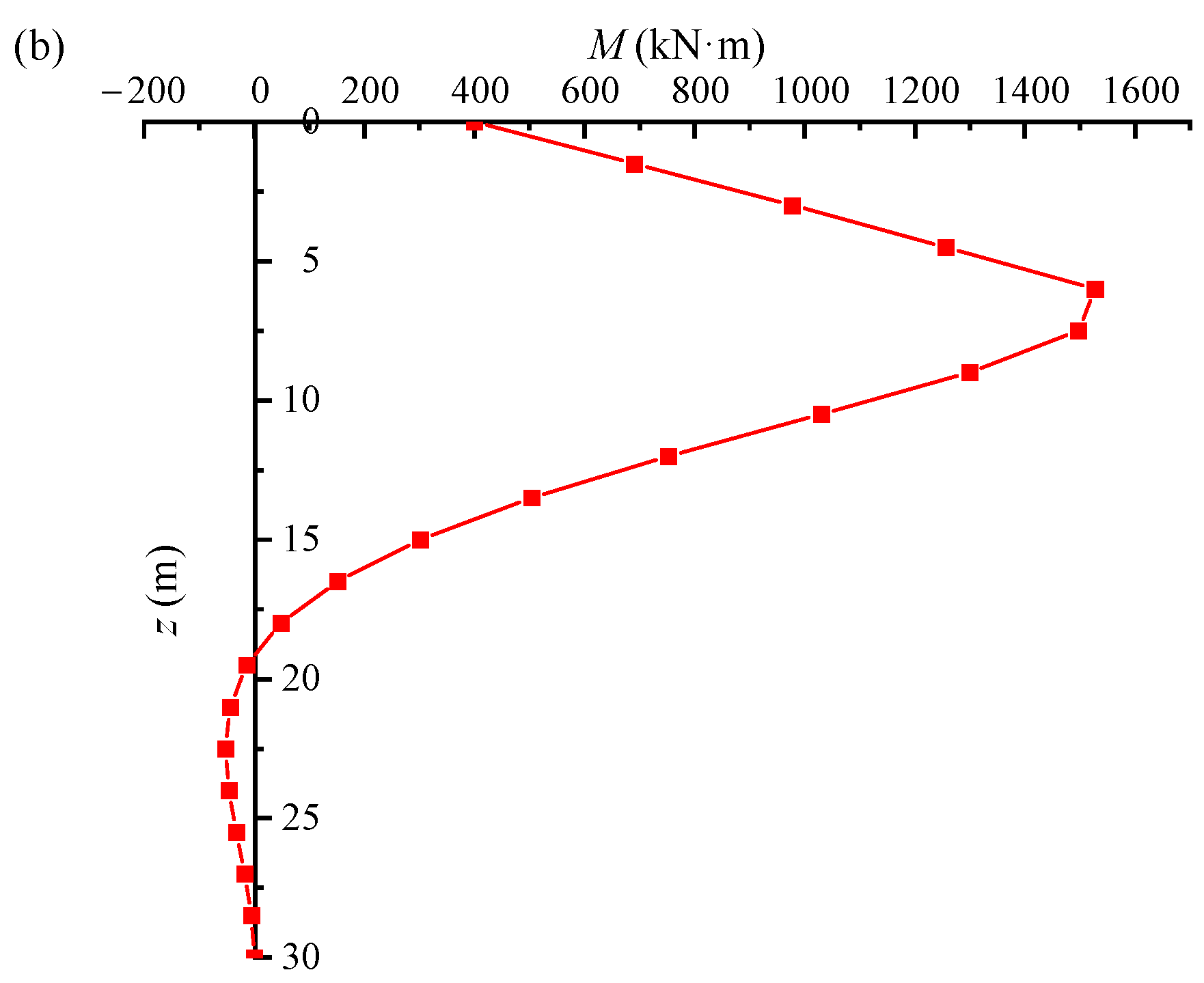
Table 2 presents the parameter values utilized to examine the time-dependent characteristics of the pile foundation’s horizontal bearing behavior under the combined effects of scouring and chloride ion corrosion. When a lateral displacement of 100 mm (yth =100 mm) is applied to the pile head, the critical scour depth is found to be 4.5 m. Figure 2 illustrates how the pile’s lateral displacement varies with pile depth when the stiffness is not taken into account and the scour depth approaches the critical threshold.
The maximum lateral displacement of the pile is observed at the pile head, where the critical displacement reaches 100 mm. As the pile depth increases, the lateral displacement gradually decreases, becoming zero at a depth of 10.5 m. Beyond this point, the displacement turns negative, with the most significant negative lateral displacement occurring at 15 m. The pile experiences its maximum bending moment at the critical scour depth, which is defined as 100 mm. The highest bending moment is reached at a depth of approximately 6 m, and it continues to increase steadily over time. A negative bending moment develops at around 19 m, with the peak negative bending moment occurring near 22.5 m.
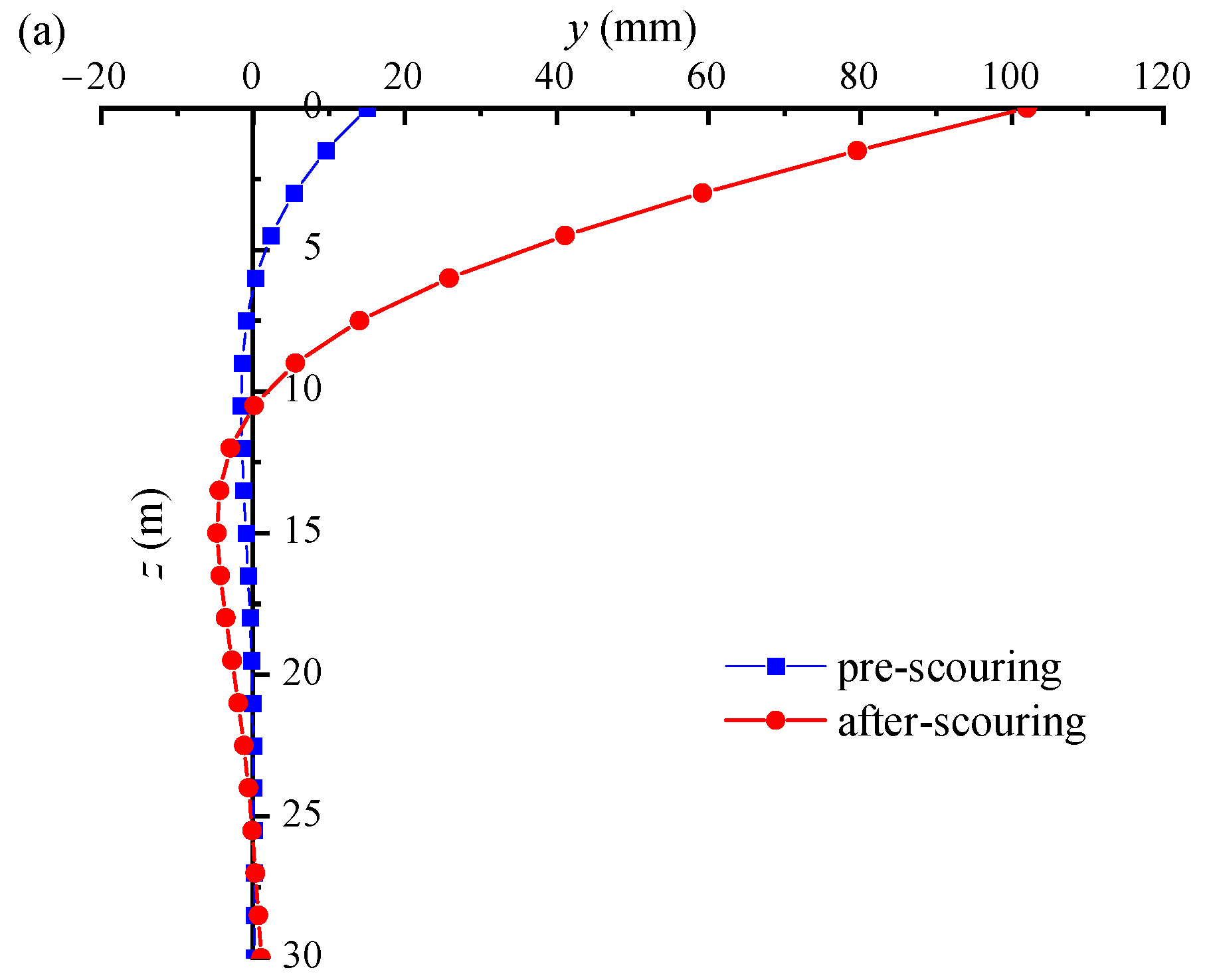
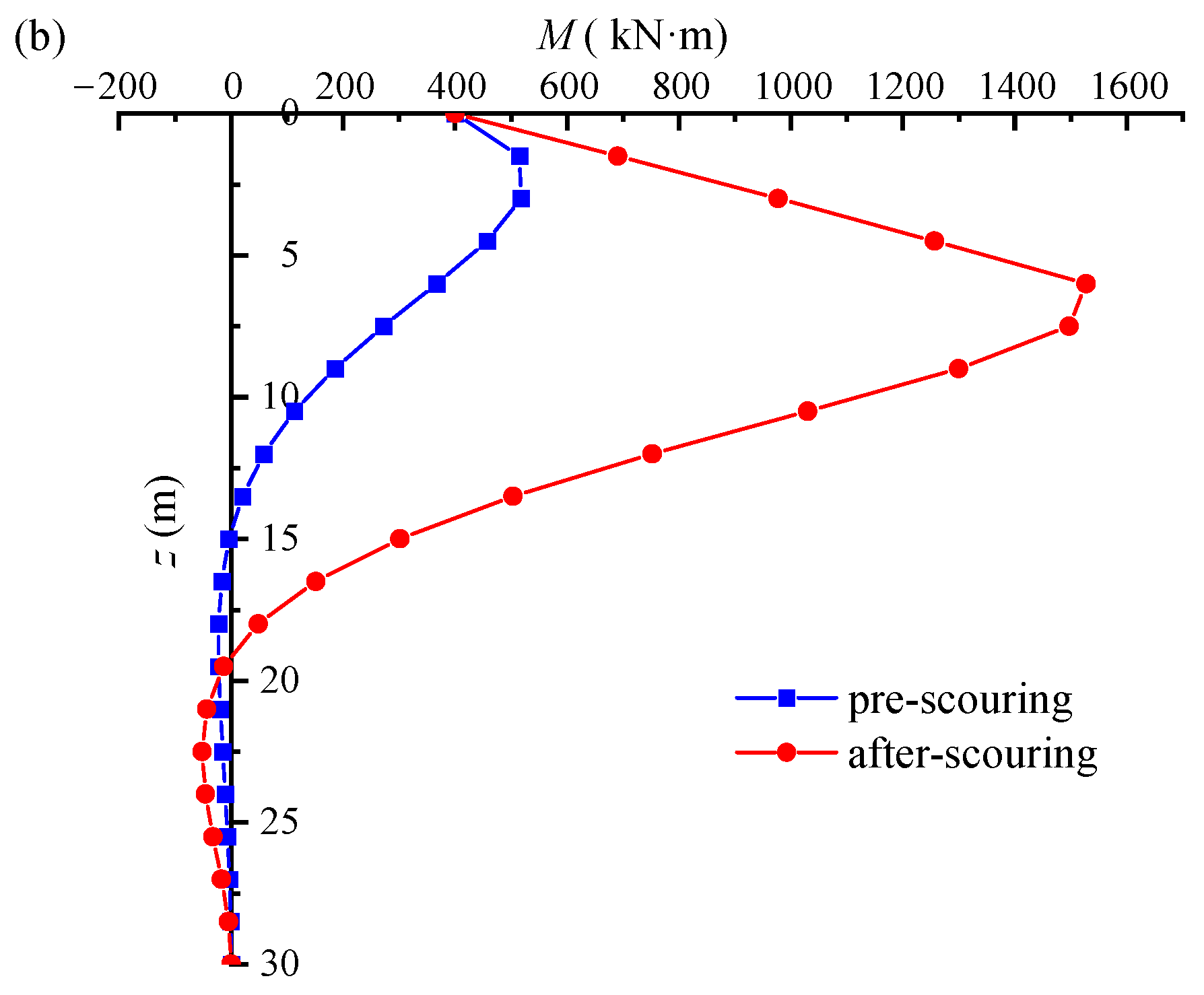
Figure 3 illustrates the variations in the lateral displacement and bending moment of the pile foundation as a function of the critical scour depth. It can be observed that the maximum lateral displacement occurs at the pile top both before and after scouring. This displacement increases from 15 mm to 100 mm, while the depth at which lateral displacement becomes zero shifts from 6 m to 10.5 m prior to scouring. Beyond this depth, the displacement transitions to negative values. The maximum negative lateral displacement also increases from a location at a depth of about 9 m to 15 m. As shown in Figure 3b, the maximum bending moment increases from an initial value of 517.9 kN·m to 1527.1 kN·m following scouring. The location where the negative bending moment appears also increases from 15 m to 19.5 m. It is evident that scouring has a more noticeable impact on the pile when subjected to lateral load.
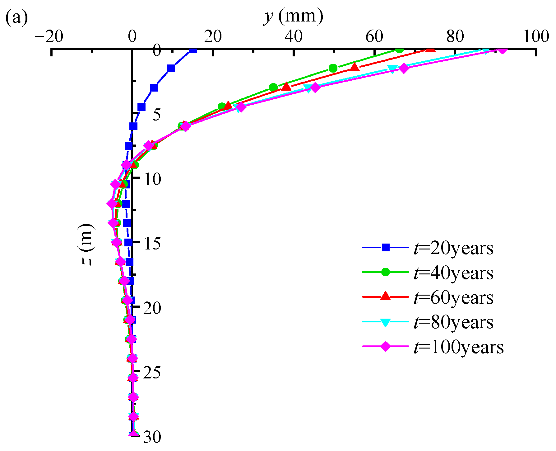
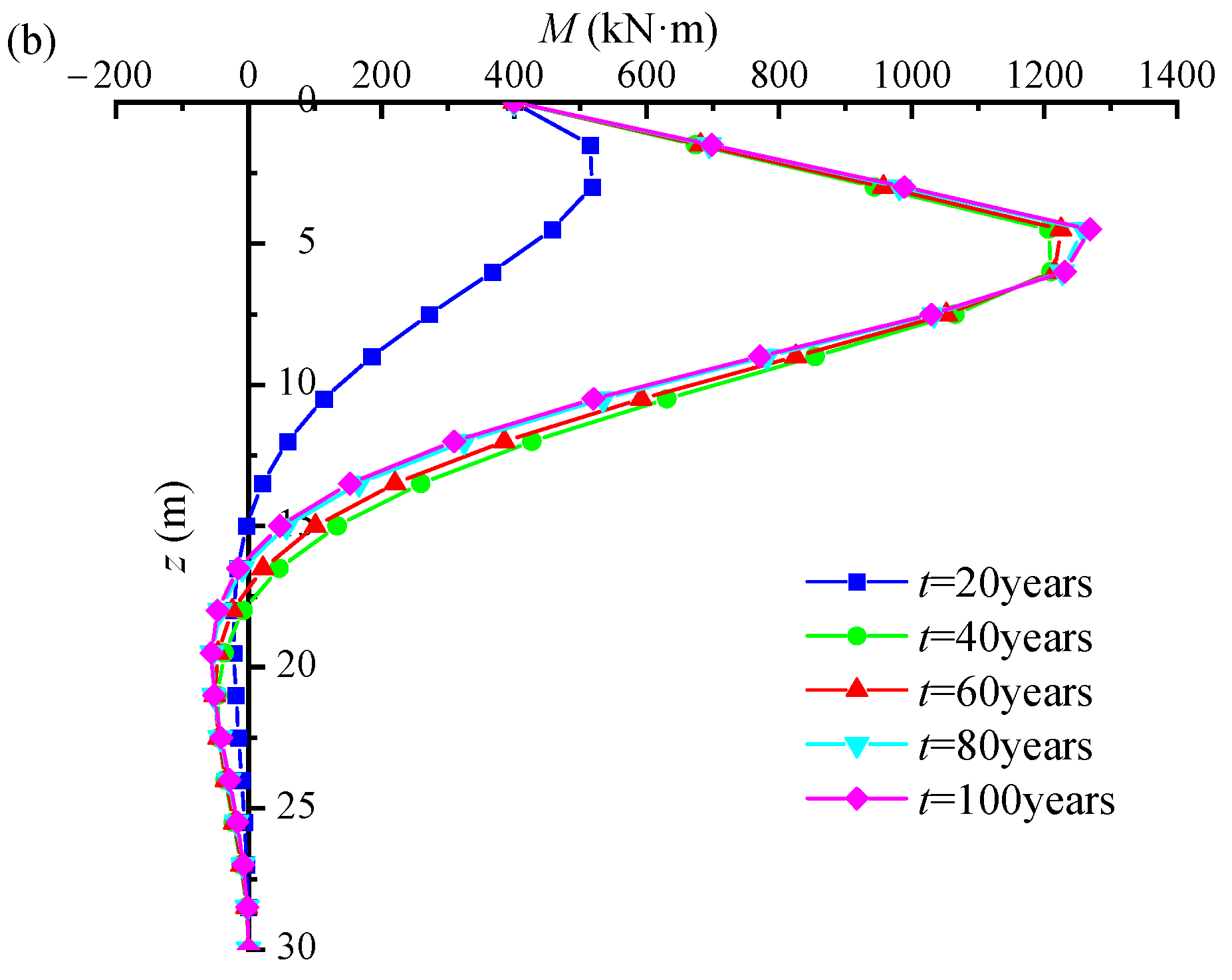
Figure 4 illustrates the relationship between the lateral displacement and bending moment of the pile foundation and the exposure duration under the conditions of seawater velocity v = 5 m/s and a resulting scour depth of 3 m. The maximum lateral displacement of the pile occurs near the top, varying between 15 mm and 91 mm. As the exposure duration increases from 20 to 100 years, the maximum lateral displacement at the pile’s top position increases from 15 mm to 91.7 mm. At approximately 9 m depth, a negative lateral displacement is observed. Over time, the lateral displacement of the pile foundation increases, eventually exceeding the critical threshold, which leads to failure of the foundation. The highest bending moment in the corroded pile occurs at a depth of approximately 4.5 m. With the exposure duration extending from 20 to 100 years, the maximum bending moment increases from 517.9 kN·m to 1268.9 kN·m. At a depth of around 16 m, the bending moment becomes negative. The peak negative bending moment rises from 22.3 kN·m to 56.1 kN·m. It is worth noticing that after the first corrosion time, the location of the pile’s greatest negative bending moment gradually moves closer to the top.

3.4. Scour Depth Probability Prediction

The variation in the scour depth over the reference value with seawater velocity is represented in Figure 5.
As can be observed, the likelihood of the scour depth around the pile base exceeding the reference value increases with rising seawater velocity. In detail, given a seawater velocity of 5 m/s, the likelihood of surpassing the reference scour depth reduces as the reference value increases. The likelihood of exceeding this value drops from 0.567 to 0.117 for scour depths ranging from 0.00 mm to 900 mm. The probability of surpassing the reference value rises with seawater velocity. As seawater velocity increases from 2.0 m/s to 8.0 m/s, the probability of surpassing the 900 mm reference value increases from 0.0114 to 0.1836.

3.5. Time-Varying Failure Probability

The values employed in the reliability analysis are presented in Table 3. By introducing the variation rules of pile stiffness reduction coefficient with exposure time and scour depth with seawater velocity, the failure probability of the time-varying characteristics of piles under the coupled conditions of chloride ion corrosion and scour is obtained.
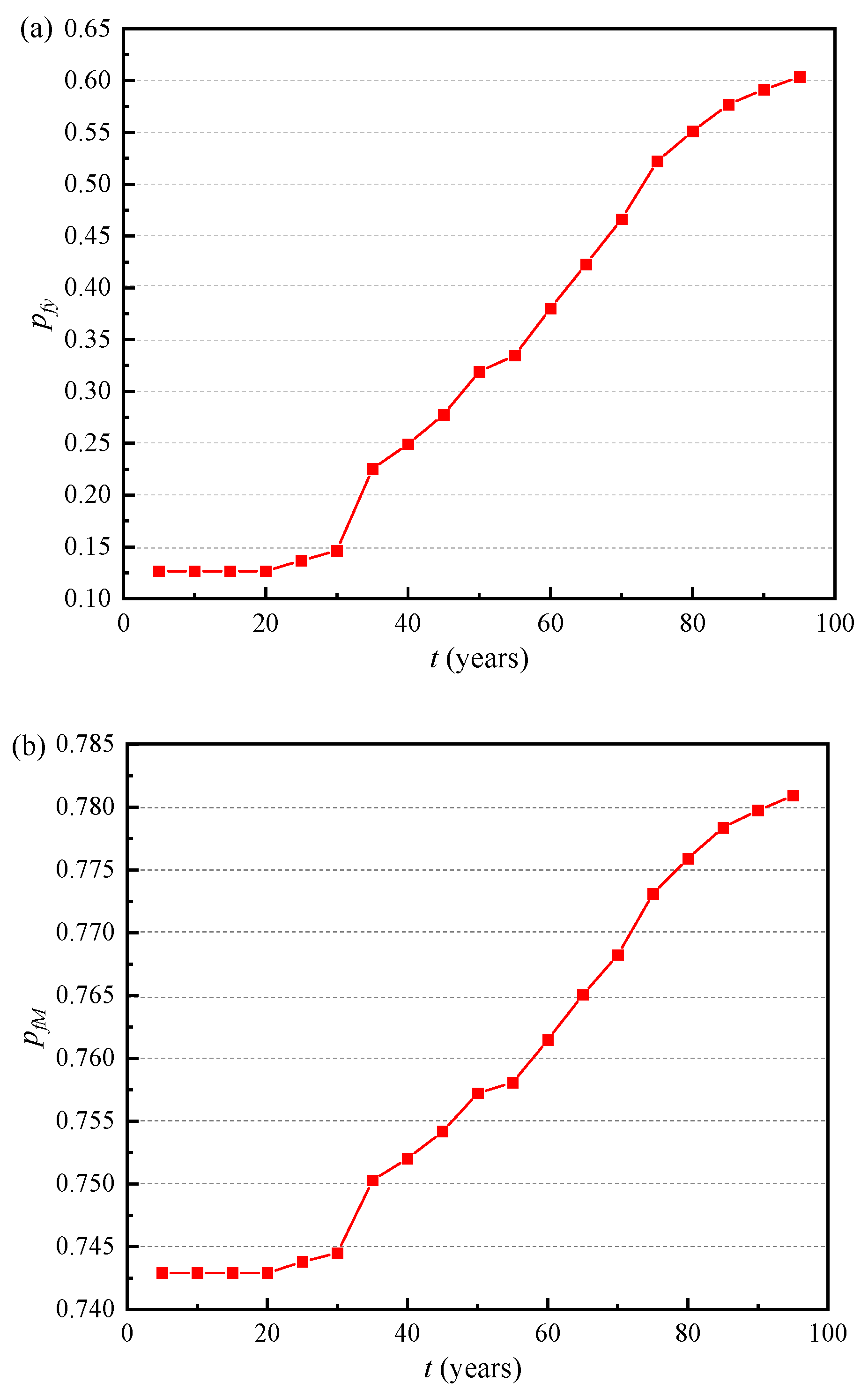
Figure 6 depicts the time-varying law of failure probability for pile foundations under longitudinal displacement failure criteria and bending moment failure criteria. Under the two failure criteria, the failure probability of the pile foundation remains constant during the initial stages of corrosion. Subsequently, the likelihood of failure increases progressively with prolonged exposure. Specifically, the failure probability rises from 0.13 to 0.60 under the horizontal displacement criterion, and from 0.74 to 0.78 under the bending moment criterion. Notably, the failure probability associated with horizontal displacement increases at a faster rate than that observed under the bending moment criterion. This suggests that the pile foundation is more susceptible to failure under lateral displacement than under bending moment conditions.

3.6. Parametric Analysis

3.6.1. Bending Moment at Top of Pile

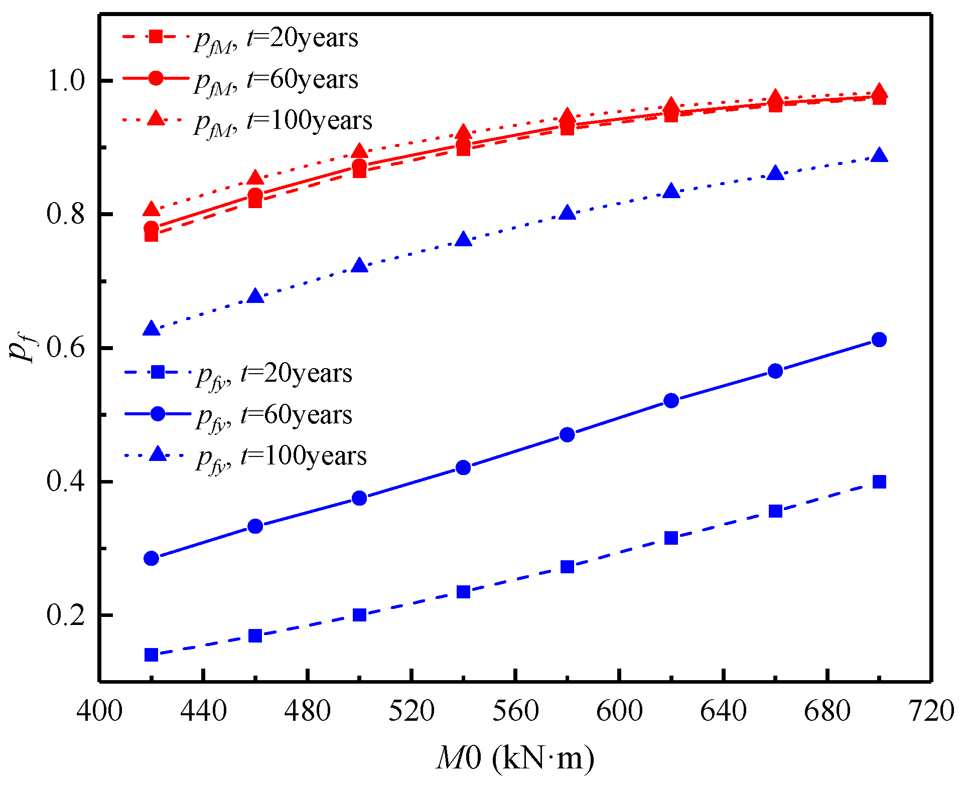
Figure 7 illustrates the correlation between the failure probability and the average bending moment at the top of the pile. The plot demonstrates that both the failure probabilities associated with the lateral displacement and bending moment increase as the average bending moment grows over a specified exposure period. In particular, the failure probabilities of lateral displacement under the failure criteria increase from 0.14, 0.28, and 0.63 to 0.40, 0.61, and 0.89, respectively, and the failure probabilities of the bending moment under the failure criteria increase from 0.77 to 0.973, 0.78 to 0.976, and 0.81 to 0.982, respectively, when the mean value of the bending moment increases from 420 kN·m to 700 kN·m and the exposure time is 20, 60, and 100 years. However, for a mean bending moment of 500 kN·m, the likelihood of failure rose from 0.20 to 0.72 for lateral displacement and 0.86 to 0.89 for bending moment as the exposure duration increased from 20 to 100 years. In contrast, lateral displacement is more susceptible to the impact of the mean bending moment under the failure criterion.

3.6.2. Lateral Load at Top of Pile

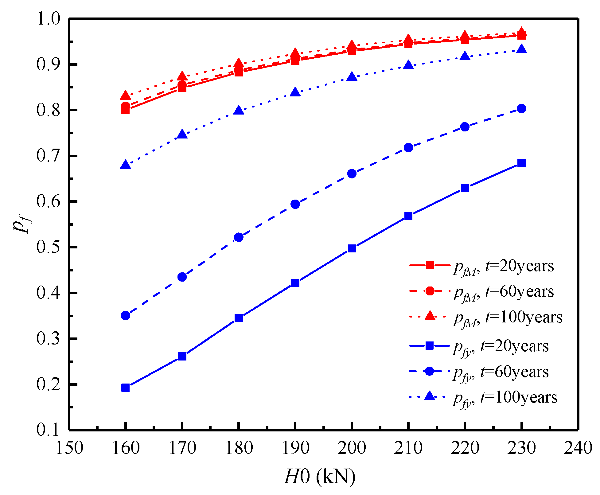
Figure 8 illustrates the impact of the average lateral load at the top of the pile foundation on the failure probability. The graph reveals that, as the mean lateral load increases, the failure probability, according to various failure criteria, rises steadily. This is due to the substantial lateral displacement that can occur at the top of the pile foundation when subjected to both lateral load and scour effects. Specifically, as the mean lateral load increases from 160 kN to 230 kN, the failure probability of pile foundation lateral displacement increases from 0.19 to 0.68, 0.35 to 0.80, and 0.68 to 0.93 for exposure durations of 20, 60, and 100 years, respectively. Additionally, the failure probability related to the bending moment of the pile foundation increases from 0.80 to 0.96, from 0.81 to 0.96, and from 0.83 to 0.97. With a lateral load of 200 kN, the failure probabilities of lateral displacement and bending moment under their respective failure criteria increased from 0.50 to 0.97 and 0.93 to 0.94, respectively, with increasing exposure time from 20 to 100 years. In contrast, lateral displacement is more susceptible to the impact of the average lateral load under the failure criterion.

3.6.3. Vertical Load at Top of Pile

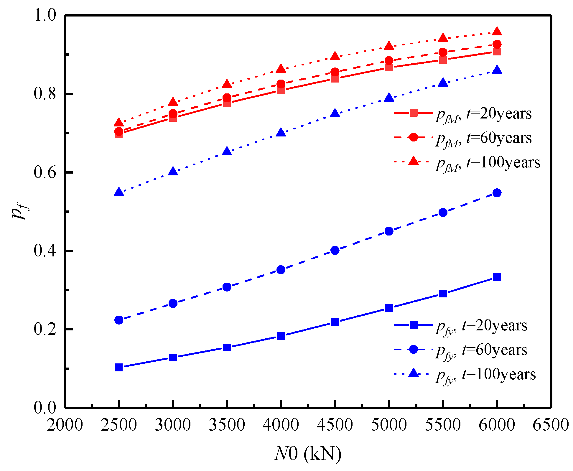
The effect of the mean value of vertical load on the failure probability is represented by Figure 9.
It is evident that when the mean value of the vertical load grows during a certain exposure time, the pile foundation’s failure probability progressively rises. At exposure durations of 20, 60, and 100 years, the probability of failure based on the bending moment criterion increases from 0.698 to 0.907, 0.704 to 0.926, and 0.725 to 0.957, respectively. Meanwhile, the failure probability associated with lateral displacement rises from 0.103, 0.224, and 0.548 to 0.333, 0.548, and 0.859, respectively, as the average vertical load increases from 2500 kN to 6000 kN. When the mean vertical load is 4500 kN, the failure probability for lateral displacement of the pile foundation increases from 0.218 to 0.748 as the exposure time extends from 20 to 100 years. Under the bending moment failure criterion, the probability of failure increases from 0.839 to 0.894. Furthermore, the disparity in the failure probabilities for the bending moment becomes more pronounced as the exposure time increases, even at the same vertical load.

3.6.4. Time-Varying Properties Under the Influence of Seawater Velocity

Figure 10 illustrates the temporal variation in the failure probability of the bending moment and lateral displacement as influenced by seawater velocity. It is clear that with an increase in exposure time, the likelihood of failure for both the lateral displacement and bending moment of the pile foundation also increases. Furthermore, under identical exposure durations, the failure risk escalates as seawater velocity intensifies. Specifically, as the exposure duration extends from 5 to 95 years, the probability of pile foundation lateral displacement failure rises from 0.0076 to 0.1812, 0.0270 to 0.3373, and 0.1570 to 0.6678 at seawater velocities of 5 m/s, 6 m/s, and 7 m/s, respectively. Similarly, the probability of bending moment failure increases from 0.6029 to 0.6357, 0.6915 to 0.7293, and 0.8275 to 0.8645. As exposure time grows, the failure probability for horizontal displacement under the set failure criteria escalates, whereas the variation in the bending moment failure probability remains relatively stable. The failure probability of the lateral displacement is 0.0426, 0.1138, and 0.3829, respectively, and the failure probability of the bending moment is 0.6139, 0.7052, and 0.8420, respectively, when the exposure duration is 50 years and the seawater velocity is 5 m/s, 6 m/s, and 7 m/s. On the other hand, the lateral displacement’s failure probability is more susceptible to the impact of seawater velocity.

4. Conclusions

The main aim of this study is to estimate the stiffness degradation coefficient of a pile foundation subjected to chloride ion corrosion, with the goal of determining the foundation’s initial corrosion onset. A probabilistic analysis is conducted to assess reference values for scour depth. Utilizing the Monte Carlo simulation approach, the degradation coefficient of pile flexural stiffness is introduced to evaluate the reliability of the bearing capacity of laterally loaded piles in a chloride ion environment. The failure probability of the pile foundation, in terms of lateral displacement and bending moment, is analyzed within the context of combined chloride ion corrosion and scour conditions, considering failure criteria for both the bending moment and lateral displacement. Additionally, the influence of key factors on the failure probability is investigated. The results show the following:
(1)
The stiffness reduction coefficient of the pile foundation decreases gradually with increasing exposure time. When the scour depth reaches a critical value, it has a large effect on both the lateral displacement and the bending moment. With increasing exposure time, the lateral displacement and bending moment generated by the pile also increase. As the seawater velocity increases, the probability of exceeding the reference value of scour depth around the pile base also increases.
(2)
Under the two failure criteria, the lateral displacement and bending moment of the piles remain constant until the initial corrosion time, but then gradually increase with the increase in exposure time. Comparing the failure probability of lateral displacement and bending moment, it can be found that the failure probability of lateral displacement is more sensitive to the exposure time. At the same exposure period, the pile foundation’s failure probability increases as the average values of bending moment, lateral load, and vertical load rise.
(3)
Increasing seawater velocity increases the likelihood of pile foundation failures, including that of the lateral displacement and bending moment. And the sensitivity of the lateral displacement failure probability is still greater than the bending moment failure probability. Therefore, the lateral displacement failure criterion is more suitable as the determination criterion of lateral bearing pile failure.

Author Contributions

Conceptualization, B.C. and C.W.; data curation, W.Z. (Wei Zhang); formal analysis, C.W.; investigation, B.C.; funding acquisition, C.W.; methodology, W.Z. (Wenbing Zhang) and C.W.; resources, C.W.; software, B.C.; supervision, W.Z. (Wenbing Zhang), S.F., and J.D.; validation, B.C. and C.W.; visualization, B.C.; writing—original draft, B.C.; review and editing, C.W. and W.Z. (Wenbing Zhang). All authors have read and agreed to the published version of the manuscript.

Funding

This research was financially supported by the China Three Gorges Corporation (Grant No. 202103495).

Data Availability Statement

Data are contained within the article.

Conflicts of Interest

Author Bo Chen, Caihong Wu, Wei Zhang, Shenghua Fan, Jialin Dai was employed by the company China Three Gorges Corporation. The remaining authors declare that the research was conducted in the absence of any commercial or financial relationships that could be construed as a potential conflict of interest.

References

  1. Li, C.Q. Initiation of chloride-induced reinforcement corrosion in concrete structural members-prediction. ACI Struct. J. 2002, 99, 133–141. [Google Scholar] [CrossRef]
  2. Zhou, L.; Alam, M.S.; Dong, Y.; Ruiwei, F. Seismic resilience assessment of extended pile shaft supported coastal bridges considering scour and uniform corrosion effects. Eng. Struct. 2024, 304, 117643. [Google Scholar] [CrossRef]
  3. Zhang, M.; Sun, S.; Liu, K.; Li, T.; Yang, H. Research on the critical chloride content of reinforcement corrosion in marine concrete—A review. J. Build. Eng. 2023, 79, 107838. [Google Scholar] [CrossRef]
  4. Li, J.P.; Shao, W. The effect of chloride binding on the predicted service life of RC pipe piles exposed to marine environments. Ocean Eng. 2014, 88, 55–62. [Google Scholar] [CrossRef]
  5. Shao, W.; Shi, D.; Jiang, J.; Chen, Y. Time-dependent lateral bearing behavior of corrosion-damaged RC pipe piles in marine environments. Constr. Build. Mater. 2017, 157, 676–684. [Google Scholar] [CrossRef]
  6. Jiang, C.; Guo, S.; Shao, X. A time-variant non-probabilistic reliability assessment strategy for laterally loaded offshore monopiles under scour and corrosion. Ocean. Eng. 2024, 310, 118714. [Google Scholar] [CrossRef]
  7. Bastidas-Arteaga, E.; Bressolette, P.; Chateauneuf, A. Probabilistic lifetime assessment of RC structures under coupled corrosion-fatigue deterioration processes. Struct. Saf. 2008, 31, 84–96. [Google Scholar] [CrossRef]
  8. Zhang, Y.; Zhou, X.; Zhang, Y. Randomness of bidirectional chloride corrosion of sluice gate and time to corrosion initiation of reinforcement in a strong tidal environment. Constr. Build. Mater. 2019, 227, 116707. [Google Scholar] [CrossRef]
  9. Kioumarsi, M.M.; Hendriks, M.A.N.; Kohler, J.; Geiker, M.R. The effect of interference of corrosion pits on the failure probability of a reinforced concrete beam. Eng. Struct. 2016, 114, 113–121. [Google Scholar] [CrossRef]
  10. Firouzi, A.; Abdolhosseini, M.; Ayazian, R. Service life prediction of corrosion-affected reinforced concrete columns based on time-dependent reliability analysis. Eng. Fail. Anal. 2020, 117, 104944. [Google Scholar] [CrossRef]
  11. Homaei, F.; Mohammad, N. Failure analysis of scouring at pile groups exposed to steady-state flow: On the assessment of reliability-based probabilistic methodology. Ocean Eng. 2022, 266, 112707. [Google Scholar] [CrossRef]
  12. Khalid, M.; Mohd, M.; Javed, A. A reliability-based assessment of live bed scour at bridge piers. J. Hydraul. Eng. 2019, 27, 105–112. [Google Scholar] [CrossRef]
  13. Homaei, F.; Najafzadeh, M.A. Reliability-based probabilistic evaluation of the wave-induced scour depth around marine structure piles. Ocean Eng. 2020, 196, 106818. [Google Scholar] [CrossRef]
  14. Jafari-Asl, J.; Ben Seghier, M.E.A.; Ohadi, S.; Dong, Y.; Plevris, V. A comparative study on the efficiency of reliability methods for the probabilistic analysis of local scour at a bridge pier in clay-sand-mixed sediments. Modeling 2021, 2, 63–77. [Google Scholar] [CrossRef]
  15. Wu, M.; Vasiliki, S.; Tiago, F.-F. Experimental uncertainty analysis of monopile scour protection stability test. Renew. Energy 2023, 210, 174–187. [Google Scholar] [CrossRef]
  16. Shao, W.; Nie, Y.; Liang, F. A novel comprehensive evaluation method for the corrosion initiation life of RC hollow piles in chloride environments. Constr. Build. Mater. 2020, 249, 118801. [Google Scholar] [CrossRef]
  17. Maeda, S.; Takewaka, K.; Yamaguchi, T. Quantification of chloride diffusion process into concrete under marine environment. Proc. Jpn. Soc. Civ. Eng. 2004, 63, 109–120. [Google Scholar]
  18. Shao, W.; Zhang, W.; Shi, D.D.; Xu, Y.Z.; Liu, E.L. Time-varying characteristics of the durability and lateral bearing behaviour of FRP bar-reinforced concrete piles in marine environments. Constr. Build. Mater. 2021, 302, 124192. [Google Scholar] [CrossRef]
  19. Maaddawy, E.T.; Soudki, K. A model for prediction of time from corrosion initiation to corrosion cracking. Cem. Concr. Compos. 2007, 29, 168–175. [Google Scholar] [CrossRef]
  20. Papakonstantinou, K.G.; Shinozuka, M. Probabilistic model for steel corrosion in reinforced concrete structures of large dimensions considering crack effects. Eng. Struct. 2013, 57, 306–326. [Google Scholar] [CrossRef]
  21. Lu, C.; Jin, W.; Liu, R. Reinforcement corrosion-induced cover cracking and its time prediction for reinforced concrete structures. Corros. Sci. 2011, 53, 1337–1347. [Google Scholar] [CrossRef]
  22. Vu, K.A.T.; Stewart, M.G. Structural reliability of concrete bridges including improved chloride-induced corrosion models. Structures 2000, 22, 313–333. [Google Scholar] [CrossRef]
  23. Shao, W.; Huang, T.; Shi, D. Time-varying behavior of corrosion-damaged piles under cyclic lateral loading in marine environments. Mar. Georesources Geotechnol. 2022, 40, 856–868. [Google Scholar] [CrossRef]
  24. Phanikanth, V.; Choudhury, D.; Reddy, R. Response of single pile under lateral loads in cohesionless soils. Electron. J. Geotech. Eng. 2020, 15, 813–830. [Google Scholar]
  25. Durability Evaluation Criteria for Concrete Structures; Architecture & Building Press: Beijing, China, 2007.
  26. Li, T.; Lin, J.; Liu, J. Analysis of time-dependent seismic fragility of the offshore bridge under the action of scour and chloride ion corrosion. Structures 2020, 28, 1785–1801. [Google Scholar] [CrossRef]
  27. Briaud, J.L.; Ting, F.C.; Chen, H.C.; Gudavalli, R.; Perugu, S.; Wei, G. SRICOS: Prediction of scour rate in cohesive soils at bridge piers. J. Geotech. Geoenvironmental Eng. 1999, 125, 237–246. [Google Scholar] [CrossRef]
  28. Shao, W.; Nie, Y.; Shi, D. Probabilistic analysis of the behaviour of laterally loaded piles in chloride environments. Ocean Eng. 2020, 27, 107872. [Google Scholar] [CrossRef]
  29. Haldar, S.; Sivakumar Babu, G.L. Effect of soil spatial variability on the response of laterally loaded pile in undrained clay. Comput. Geotech. 2008, 35, 537–547. [Google Scholar] [CrossRef]
  30. Chan, C.L.; Low, B.K. Reliability analysis of laterally loaded piles involving nonlinear soil and pile behavior. J. Geotech. Geoenvironmental Eng. 2009, 135, 431–443. [Google Scholar] [CrossRef]
  31. Shao, W.; Li, J.P.; Chen, H.B.; Li, L. Time-dependant behavior analysis of laterally loaded corrosion damaged RC pipe piles. J. Harbin Inst. Technol. 2015, 47, 77. [Google Scholar]
  32. Chen, D.; Mahadevan, S. Chloride-induced reinforcement corrosion and concrete cracking simulation. Cem. Concr. Compos. 2008, 30, 227–238. [Google Scholar] [CrossRef]
  33. Reale, T.; O’Connor, A. A review and comparative analysis of corrosion-induced time to first crack models. Constr. Build. Mater. 2012, 36, 475–483. [Google Scholar] [CrossRef]
  34. Su, D.; Huang, J.J.; Yan, W.M. Parametric investigation on the responses of laterally loaded piles in over-consolidated clay using nondimensional solutions addressing nonlinear soil-pile interaction. Comput. Geotech. 2018, 96, 203–214. [Google Scholar] [CrossRef]
  35. Collepardi, M.; Marcialis, A.; Turriziani, R. Penetration of chloride ions into cement pastes and concrete. J. Am. Ceram. Soc. 1972, 55, 534–535. [Google Scholar] [CrossRef]
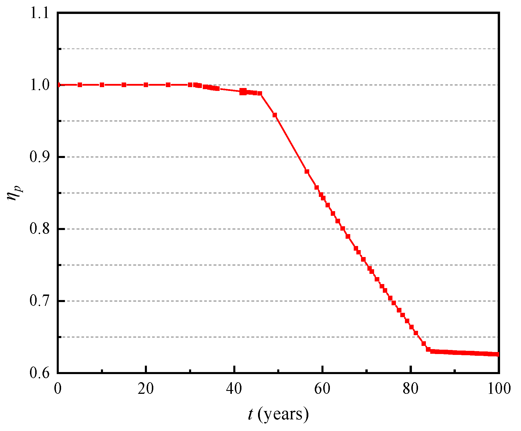
Figure 1. Time-dependent stiffness degradation coefficient.
Water 17 00084 g001
Figure 2. Variations in pile bearing behavior with depth: (a) lateral displacement and (b) bending moment.
Water 17 00084 g002aWater 17 00084 g002b
Figure 3. Variation in pile bearing behavior before and after scouring: (a) lateral displacement and (b) bending moment.
Water 17 00084 g003aWater 17 00084 g003b
Figure 4. Variations in pile bearing behavior with time: (a) lateral displacement and (b) bending moment.
Water 17 00084 g004aWater 17 00084 g004b
Figure 5. Variation in the probability that the scour depth exceeds the reference depth with seawater velocity.
Water 17 00084 g005
Figure 6. Time-dependent failure probability under the failure criterion for the (a) lateral displacement and (b) bending moment.
Water 17 00084 g006
Figure 7. Influence of the mean bending moment on the failure probability.
Water 17 00084 g007
Figure 8. Influence of mean horizontal load on the failure probability.
Water 17 00084 g008
Figure 9. Effect of the average vertical load on the probability of failure.
Water 17 00084 g009
Figure 10. Time-varying law of failure probability of pile bearing behavior under the influence of seawater velocity: (a) lateral displacement and (b) bending moment.
Water 17 00084 g010
Table 1. Concrete mixture proportions for the piles.
VariablesUnitMeaningValueReference
Dam2/sChloride diffusion coefficient1.0 × 10−12[31]
Cskg/m3Surface chloride concentration8
w/b-Water–binder ratio0.35
Cthkg/m3Chloride threshold concentration1.2[5]
d0mmReinforcement diameter32
ρsg/cm3Density of the reinforcing steel7.85[32]
δ0μmPorous layer thickness12
νc-Poisson’s ratio of concrete cover0.20[32]
φc-Concrete creep coefficient2.0[33]
αv-Volume expansion rate of corrosion products3.0[31]
fctMPaTensile strength of the concrete2.0
EcGPaElastic modulus of the pile concrete38[31]
ammInternal radius of the hollow pile360
bmmExternal radius of the hollow pile500
DmmPile diameter1000
cmmThickness of the concrete cover55
Table 2. Parameter values used in the analysis of the time-varying characteristics of pile foundation under horizontal loading.
VariablesUnitMeaningValue
MkN·mBending moment at pile top400
HkNLateral load at pile top150
NkNVertical load at pile top3000
EskN/m2Elastic modulus of the soil5000
LmLength of the pile embedded in the soil30
n-Number of elements100
Table 3. Random variables used in reliability analysis.
VariablesUnitProbability DistributionMeanCOVReference
MthkN·mConstant (non-random)1088-[29]
ythmmConstant (non-random)100-
H0kNNormal1500.25[28]
N0kNConstant (non-random)3000-
M0kN·mNormal4000.15[28]
EskN/m2Lognormal50000.10[34]
EcGPaNormal380.15[35]
Disclaimer/Publisher’s Note: The statements, opinions and data contained in all publications are solely those of the individual author(s) and contributor(s) and not of MDPI and/or the editor(s). MDPI and/or the editor(s) disclaim responsibility for any injury to people or property resulting from any ideas, methods, instructions or products referred to in the content.