Review

Technical Analysis and Application Prospects of Magnetic Source Transient Electromagnetic Coil Devices in Hydrogeological Survey of Mining Area

1
School of Mechanics and Civil Engineering, China University of Mining and Technology, Xuzhou 221116, China
2
State Key Laboratory of Intelligent Construction and Healthy Operation & Maintenance of Deep Underground Engineering, China University of Mining and Technology, Xuzhou 221116, China
3
Yunlong Lake Laboratory of Deep Earth Science and Engineering, Xuzhou 221116, China
*
Author to whom correspondence should be addressed.
Water 2025, 17(2), 171; https://doi.org/10.3390/w17020171
Submission received: 21 November 2024 / Revised: 26 December 2024 / Accepted: 9 January 2025 / Published: 10 January 2025
(This article belongs to the Special Issue Engineering Hydrogeology Research Related to Mining Activities)

Abstract

:
The transient electromagnetic method (TEM) has a wide range of applications in the hydrogeological exploration of mining engineering. This method is highly sensitive to groundwater responses and provides reliable data for the prevention of water-related disasters, such as sudden water surges and gushes. However, there are currently a lack of comprehensive and systematic analyses and summaries regarding the characteristics of magnetic source transient electromagnetic coil devices. Based on the fixed characteristics of the field source, this paper categorizes magnetic source transient electromagnetic coil devices into fixed-source devices and moving-source devices. It provides an in-depth introduction and analysis of the working principles, technical characteristics, existing applications, and development trends of these two types of devices. This study provides important references for the selection and application of magnetic source transient electromagnetic coil devices. In the future, the development of magnetic source transient electromagnetic devices will focus on deeper measurement depths, higher lateral resolution, non-contact coupling, and efficient detection, moving towards multifunctionality, automation, and intelligence. This paper can provide a technical reference for the selection of magnetic source transient electromagnetic coil devices and their application in hydrogeological exploration of mining engineering.

1. Introduction

In mining engineering, water accidents are one of the main causes of casualties and economic losses, and their suddenness and concealment make prevention work particularly crucial. Therefore, prior to mining activities, there is an urgent need for a precise geophysical method to effectively determine the location and extent of groundwater, and provide references for the prediction of water-related disasters. The transient electromagnetic method (TEM) is a time-domain electromagnetic detection technique. When subjected to a single current pulse field excitation, the medium generates eddy currents. During the pulse interruption, these eddy currents do not disappear immediately, but instead form secondary magnetic fields in the surrounding space that decay over time. The temporal decay behavior of secondary magnetic fields is primarily influenced by the resistivity, volumetric scale, and burial depth of the anomalous body, as well as the waveform and frequency of the emitted current [1]. The magnetic source TEM uses ungrounded loops to generate transient magnetic fields as excitation sources. By measuring and analyzing secondary field signals, the characteristics of underground anomalies can be inferred. This method is extremely sensitive to the detection of low-resistivity geological bodies, particularly in the detection of water-rich strata, and is widely recognized in geophysical exploration [2].
As the core component of the system, transient electromagnetic coil devices are continually being developed and refined, with numerous scholars subsequently undertaking extensive design and research work [3,4,5,6]. In response to complex detection environments and diverse detection requirements, the variety of coil devices is expanding, and the methods for their classification are becoming increasingly diverse [7]. Overall, the development of transient electromagnetic coil devices presents the following characteristics: (1) To effectively eliminate mutual inductance effects and satisfy diverse detection requirements and geological environments, the design of coil configurations is progressively becoming multifunctional and refined, with the widespread adoption of new detection equipment, such as multi-component coils and conical coils; (2) To enhance detection accuracy and resolution, coil device designs frequently incorporate advanced technological methods, including distributed, arrayed, and equivalent reverse magnetic flux techniques; (3) To accommodate complex geological environments and acquire abundant geological data, the functionality of coil devices is leaning towards automation and intelligence, with mechanically equipped coils, such as towed, vehicle-mounted, and airborne coil devices, being extensively utilized. However, no scholars have yet conducted a systematic analysis of the characteristics of various types of coil devices, and the summary of the applicable scenarios for these coil devices remains incomplete.
This study aims to systematically and comprehensively summarize the technical analysis and application of magnetic source transient electromagnetic coil devices. By investigating numerous application cases of coil devices, it classifies and evaluates the characteristics and applicability of various devices, and briefly examines the development trends of magnetic source transient electromagnetic coil devices, with the goal of providing essential technical references for applications in the field of transient electromagnetic exploration.

2. Classification and Summary of Coil Devices

The TEM devices primarily consist of a transmitter, transmitter coils, a receiver, and receiver coils. The transmitter coils generate a primary field through step-off signals provided by the transmitter. The medium generates eddy currents under the excitation of a primary field. When the excitation is interrupted, the eddy currents within the medium do not dissipate immediately, but instead form a secondary field around it. The receiver coils receive and analyze the secondary field signals, obtaining curves of induced voltage versus time [1]. By analyzing these curves, the resistivity of the target area is determined. If the detection area consists of a homogeneous medium, the curve is linear; if the detection area comprises heterogeneous media, the curve is non-linear. By analyzing the anomalies in the curve and considering the differences in resistivity, the location of the anomalous body can be inferred [2]. Generally, the resistivity of water is significantly lower than that of soil and rock; therefore, employing this method to determine the distribution of groundwater is highly effective.

2.1. Classification Methods for Various Coil Devices

The coil devices of the TEM exhibit diverse characteristics in their design [8]. From the perspective of coil geometry, they can be classified into circular, square, and figure-eight coils. In terms of the number of turns wound within the coil, there are single-turn and multi-turn distinctions. Additionally, regarding the layout and combination strategies of coils, various types such as central loops, overlapping loops, dipole loops, bucking coils, and equivalent reverse magnetic flux coils are included. These designs not only reflect the flexibility of the TEM in adapting to different geological conditions and exploration objectives, but also demonstrate the continuous optimization and advancement of this technology in enhancing detection accuracy and efficiency [9,10].
However, in the current academic research field, there has yet to be a universally recognized and standardized classification system to systematically categorize these devices. Simply listing them based on their external morphology fails to establish a standardized evaluation framework, is lacking in logic and unable to ensure systematic and orderly classification. Classifying coil devices based on their application scenarios also faces issues of blurred boundaries and overlapping categories, because the same type of coil device may be suitable for multiple different application scenarios, and a single application scenario may give rise to a variety of coil devices.
In light of this, this study proposes a classification method based on whether the field source (emission source) of the TEM coil device is fixed. Magnetic source transient electromagnetic coil devices are categorized into fixed-source devices and moving-source devices, as shown in Table 1 below. This classification strategy effectively avoids the aforementioned two types of problems, providing a new perspective for the study of transient electromagnetic coil devices.

2.2. Fixed Source Devices

2.2.1. The Large Fixed-Source Loop

The large fixed-source loop, also known as the large, fixed emission-movable reception combination, typically utilizes a large emission and small reception setup. This configuration facilitates the measurement of induced signals generated by the magnetic field both within and outside the loop, thereby acquiring geological information of the target area [11]. The advantages of this device include larger emission coils capable of generating stronger electromagnetic fields, inducing stronger currents deep underground, and typically achieving greater detection depths [12]. Additionally, since the emission coils are positioned above ground, they are less susceptible to terrain influences, reducing construction difficulty and making them suitable for deployment in complex terrains. However, the construction of this device involves a substantial workload and is highly inconvenient. Moreover, it usually requires the use of high-power emitters, and the material requirements for the coils are typically higher than those of other devices, resulting in increased installation costs [13]. Furthermore, this device generally necessitates a large working area, which may be limited by site conditions. Large fixed-source loop devices are depicted in Figure 1 and Figure 2.
The large fixed-source loop was first developed abroad and has been widely applied in the field of petroleum exploration. In China, it is primarily used for detecting goaf areas. In 2011, Zhipeng Qi et al. [14] conducted large fixed-source loop detection in a goaf area located 3 km from the urban area of Ordos, successfully delineating the extent of the goaf area. In 2015, Ziqiang Han et al. [15] detected the goaf area at the southern end of the Ningwu Coalfield in Shanxi, successfully identifying coal seam voids and water-filled goaf areas. In 2024, Jishun Pan et al. [16] conducted detection in a coal mine in Jiaozuo, rapidly identifying the location of the goaf area, thereby providing a reference for goaf surveys.
In summary, the large fixed-source loop has demonstrated its unique advantages in petroleum exploration and goaf area detection, owing to its ability to provide high-resolution electromagnetic signals of deep underground structures [17]. However, to make this technology more practical and economical, the current challenges include reducing the cost of coil materials while maintaining detection depth. Additionally, construction efficiency directly impacts the economic benefits and operational cycles of projects. Therefore, future research directions should focus on optimizing coil materials and enhancing detection efficiency.

2.2.2. The Ground-Hole TEM

The ground-hole TEM employs an above-ground transmission and underground reception approach to obtain information about target geological bodies [18]. It typically uses fixed-source devices, meaning fixed transmission sources paired with mobile reception devices for detection [19]. The transmission sources are usually large, ranging from tens to hundreds of meters, and are typically rectangular in shape to facilitate construction. The reception devices are often probes measured along drillholes, making them easier to approach underground conductive geological bodies [20]. The advantages of this setup include large transmission coils that provide high detection depth and resolution. Using traditional drill core methods, this approach can obtain information within tens or even hundreds of meters around the drillhole, effectively addressing the “single-hole view” problem. However, similar to large fixed-source devices, this setup incurs higher costs. Additionally, the positions and deviation angles of the reception probes are often difficult to determine precisely. The ground-hole setup is illustrated in Figure 3.
In the exploration of underground mineral resources, the ground-hole TEM is one of the widely applied techniques [21], originally developed abroad. In 1984, Newmont Corporation conducted ground-hole TEM detection on a copper–iron–lead–zinc polymetallic deposit in New South Wales, collecting data in the drillhole using a single-component measurement device to determine the dip, depth, and trend of the ore body [22]. J. R. Bishop et al. [23] applied the ground-hole TEM at the Reynoldsville tin mine in western Tasmania, successfully detecting tin-bearing pyrite veins beyond a depth range of over 1000 m underground. At a drillhole depth of 540 m and a distance of 75 m from the drillhole, a concealed blind ore body was discovered.
Although the ground-hole TEM has made significant theoretical progress domestically, it has primarily been used in conjunction with drilling and other methods for validation, and there are not many cases of its direct application in mineral resource exploration. In 2013, Jie Zhang et al. [24] employed the ground-hole TEM to conduct detection work in the Huangshanling lead–zinc mine area in Chizhou City, Anhui Province, China, successfully detecting a blind ore body adjacent to the drillhole at an underground depth of 690 m. In 2022, the Geophysical Exploration Research Institute of the China National Coal Geological Bureau conducted detection at a coal mine in Shanxi, successfully identifying anomalies located 100 to 200 m below the coal seam. The data were inversely processed to establish a coal strata goaf model [25].
In summary, the ground-hole TEM is widely applied in the detection of deep concealed ore bodies and goaf areas, becoming an important technology in the field of geological exploration. To further enhance the performance of this technology, future research and development efforts will focus on increasing the detection depth of the devices, including technical improvements to existing equipment, the precise construction of multi-component coordinate systems for probes, and accurate calibration of probe deviation systems.

2.3. Dynamic Source Devices

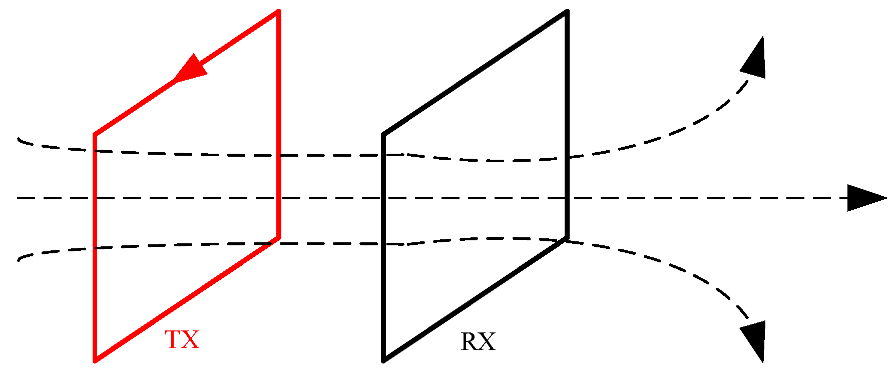
2.3.1. The Central Loop Method

The central loop method is one of the most commonly used coil device forms in TEM sounding. The transmitting loop and receiving loop are coplanar, with the receiving loop positioned at the center of the transmitting loop. The advantages of the central loop device lie in its simple structure, portability, and ability to achieve optimal coupling with the target body. It is especially suitable for high-resolution detection of shallow geological structures, and can achieve a certain exploration depth [26,27,28]. By adjusting the size of the transmitting coil, the central loop device can adapt to exploration needs under different terrain conditions, demonstrating excellent adaptability [29]. However, this type of loop device also has some limitations. For example, its detection depth is mainly restricted by the length of the transmitting loop’s sides, requiring precise control to achieve optimal detection results [30]. In specific environments, such as the seabed, the central loop device has poor resolution capabilities for a high-resistivity seabed [31]. Central loop devices are shown in Figure 4.
Transient electromagnetic central loops have a wide range of applications in the field of geological exploration, including the detection of shallow coal seam goaf areas and geoelectric model detection under complex terrains [32]. In 2019, Zhigang Li [33] applied the transient electromagnetic central loop in the survey of the Second Ring Road Tunnel in Tangshan City, identifying the distribution of karst and goaf areas beneath the tunnel. In 2020, Songwei Guo et al. [34] used the transient electromagnetic central loop in the construction of a water well in an agricultural development zone in Ming’an Town, Urat Front Banner, Inner Mongolia, precisely locating concealed faults and effectively preventing the risk of dry wells. In 2023, Hui Zhao et al. [35] employed a ground-based transient electromagnetic central loop device in a coal mine in northern Shaanxi, successfully investigating the extent and water accumulation of a large-scale shallow coal seam goaf area.
In summary, the central loop technology plays a crucial role in detecting shallow coal seam goaf areas and geoelectric models under complex terrains. However, the limitations imposed by the transmitting loop frame on detection depth and the insufficient resolution capabilities for high-resistivity seabed are current technical challenges. To overcome these limitations, it is necessary for future development directions to focus on reducing the constraints of loop frame size on detection depth and improving the central loop device’s resolution capabilities for high-resistivity seabeds.

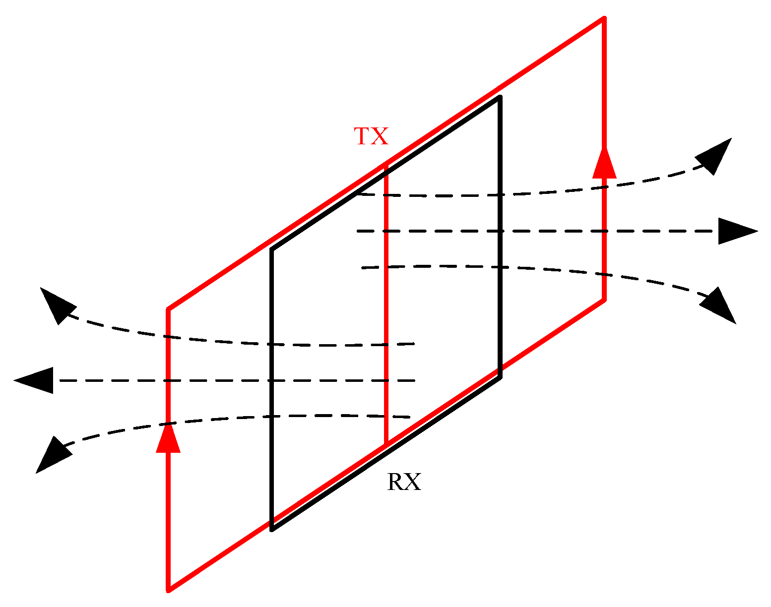
2.3.2. The Overlapping Loop

The overlapping loop (also known as the co-loop) is essentially a special type of central loop achieved by overlapping the transmitting and receiving coils. This device typically consists of two or more overlapping loops, and during operation, the transmitting and receiving coils move simultaneously [36,37,38,39]. Additionally, overlapping loops exhibit stronger adaptability to different geological conditions [40], and the accuracy of data interpretation is further enhanced [41]. However, early overlapping loops suffer from mutual inductance between the transmitting and receiving coils, resulting in blind zones in shallow exploration. Overlapping loop devices are not suitable for frequency-domain electromagnetic methods [42], and this specificity requires that, when designing and applying overlapping loop devices, their specific requirements and limitations in TEM must be considered. Overlapping loop devices are shown in Figure 5.
Transient electromagnetic overlapping loops are widely applied in geotechnical engineering surveys, hydrogeological investigations, mineral resource exploration, and geological disaster investigations. In December 2016, Haiyan Yang et al. [41] conducted a transient electromagnetic forward prediction experiment using overlapping loops in a coal mine, validating the effectiveness of the overlapping loop delay correction method and forward prediction technology. In June 2019, Sidi Ma [43] used a new overlapping loop transient electromagnetic coil device in the detection of a segment of the Xiaojian River Channel of the Hangzhou-Ningbo Grand Canal, successfully obtaining the actual excavation depth of the canal embankment. In January 2021, Dingyuan Zhuang [44] used overlapping loops to conduct exploration work in the goaf area of a coal mine, verifying that this method has significant advantages such as short construction preparation time and high operational efficiency, and obtaining geoelectric cross-section information of the goaf area. In July of the same year, Runping Guo et al. [45] used a large-current, multi-turn overlapping loop device to conduct transient electromagnetic surveys for water diversion projects in tunnel excavations, successfully delineating the range of anomalies such as goaf areas and water-bearing structures.
In summary, overlapping loop devices have significant advantages in deep exploration fields such as engineering surveys, hydrogeological investigations, and disaster exploration. However, they present considerable blind zones in shallow detections. To overcome this challenge, current research and development efforts focus on effectively reducing mutual inductance, thereby expanding the application range of overlapping loop devices in shallow detections and achieving more comprehensive geological and environmental information acquisition.

2.3.3. The Transient Electromagnetic Dipole Device

The transient electromagnetic dipole device first appeared in 1933, when it was proposed by the American scientist L.W. Blau [46]. Its basic principle is to equivalently represent the radiating probe as a magnetic dipole, utilizing the radiation effect of magnetic dipoles on electromagnetic waves in the air to achieve the detection and analysis of targets. Dipole devices can be specifically categorized into vertical magnetic dipole devices, coaxial horizontal magnetic dipole–dipole devices, and quasi-dipole devices. The advantages of dipole devices are primarily reflected in the following aspects [47,48,49]: their low sensitivity to primary fields significantly enhances detection accuracy; they exhibit strong resolution capabilities in shallow detection, particularly suitable for complex environments such as the seabed; their operational flexibility and convenience make them ideal for fieldwork; compared to overlapping loop devices, dipole devices have obvious advantages in resolution and the accuracy of determining the position of anomalous bodies. Their limitations are manifested as follows [50]: when the dipole spacing is large, the induced signals are relatively weak, making the precise localization of anomalous bodies difficult; their detection depth and signal strength are generally inferior to those of overlapping loop devices; dipole devices exhibit non-negligible errors between the approximate and exact solutions of field points within the emitting loop area, which is particularly critical for high-precision detection. Dipole devices are illustrated in Figure 6 and Figure 7.
The transient electromagnetic dipole devices have been proven suitable for various geological exploration scenarios, including seabed detection, hydrogeological surveys, tunnel advance geological forecasting, and shallow coal seam goaf detection. In terms of specific applications, some foreign scholars conducted early research on the application of dipole devices in seabed electromagnetic detection methods [51]. In 1988, R. N. Edwards studied a towed two-dimensional electric dipole–dipole seabed electromagnetic system, exploring the optimal time delay or frequency for electromagnetic imaging of seabed conductivity. These studies provided limited descriptions of the actual operational characteristics of dipole devices. Domestically, in 2015, Huiyun Li [52] successfully applied TEM dipole devices to mine water hazard prevention, proposing directions for improvement. In 2016, Guangmao Zhao [53] conducted transient electromagnetic response calculations based on irregular magnetic dipole sources, applying them to railway goaf detection and groundwater exploration in complex terrains. In 2021, Cunhuan Shi et al. [54] utilized coaxial dipole devices for tunnel advance geological forecasting studies, employing three-dimensional finite element forward modeling to verify their application potential in railway tunnel advance geological forecasting.
In summary, the application scenarios of the transient electromagnetic dipole devices have gradually expanded from initial seabed detection to hydrogeological surveys, coal seam goaf detection, and tunnel advance geological forecasting. Additionally, this study found that the research interest in this type of device has declined over the past five years. This phenomenon can be attributed to two factors: first, the inherent limitations of dipole devices have somewhat restricted their application in broader scenarios; second, the continuous innovation of transient electromagnetic coil devices in recent years has provided researchers with more options, thereby affecting the relative status of dipole devices.

2.3.4. The Well-Ground TEM

The well-ground TEM detects underground resistivity anomalies by emitting signals from downhole and receiving them at the surface [55]. Due to limited underground construction space, the emitting device typically employs multi-turn small-loop devices with diameters ranging from approximately one to three meters [56]. To maximize the reception of the magnetic fields generated by the downhole emitting coils, the receiving coils are often larger square or rectangular loops [57]. The advantages of this setup include the following: the emitting device’s small size minimizes the impact of equipment volume, making it almost negligible; the compact device offers significant flexibility, which is especially advantageous in the confined spaces of mines; multi-turn small loops can detect signals in different directions, providing strong directional sensitivity; the larger receiving coils can capture secondary field signals as completely as possible. However, the multi-turn small-loop devices have numerous turns, resulting in prolonged cutoff times; their small size leads to weaker and less stable signal strengths [58]. The well-ground device is illustrated in Figure 8.
Well-ground TEM coil devices possess unique advantages in deep anomaly detection and are widely used in mine advance detection and mine goaf water accumulation zone detection [59]. In foreign resource exploration, the focus is primarily on oil exploration, predominantly utilizing large fixed-source devices, with slow progress in the development of small-loop devices, resulting in few engineering cases [60]. Domestically, the initiation of well-to-ground transient electromagnetic work occurred later. In 2005, Shi Han [61] successfully applied TEM dipole devices to mine water hazard prevention at the Xinzheng Thermal Power Plant, proposing improvement directions through repeated observations of anomalous points to accurately locate water-bearing zones. In 2022, the Geophysical and Geochemical Exploration Research Institute of the Chinese Academy of Geological Sciences conducted mineral exploration in the Qingchengzi Baiyun Gold Mine area in Liaoning, using the Canadian Crone PEM system for simultaneous downhole and surface detection. An anomaly was detected at depths of 1400 m to 1650 m, identified as a concealed fault zone, laying the foundation for subsequent resource extraction [62].
In summary, well-ground TEM devices play a crucial role in mine advance detection and mine goaf water accumulation zone detection. To further enhance their detection accuracy and efficiency, current research focuses on reducing the inductive effects of emitting coils, lowering background noise, and improving the signal-to-noise ratio; increasing the signal strength of emitting coils, and enhancing signal penetration and coverage.

2.3.5. Magnetic Induction Probes

Magnetic induction probes are small coils wound with coaxial induction coils on a magnetic core, utilizing multiple turns of copper wire to enhance magnetic flux detection capability, thereby enabling the sensing of weaker magnetic field signals [63]. The magnetic induction probe device is illustrated in Figure 9.
In the 1970s, the Greek company CRONE developed a magnetic induction probe capable of measuring signals by adjusting angles, which was used for karst detection in karst basins [64]. In the same year, the Canadian company GEONICS combined the EM series emission system with magnetic induction probes to identify underground water resources in Charlevoix, Quebec [65].
In 2013, Kaibin Wang from the Xi’an Research Institute combined magnetic induction probes as receiving devices with the TEM system, successfully applying them to advance detection in the southern wing of the Wangzhuang coal mine [66]. In recent years, the Xi’an Institute of the China Coal Research Institute has conducted extensive forward modeling, signal feature analysis, and interpretation method research for drilled hole TEM [67,68].
Magnetic induction probes are highly sensitive and easily affected by environmental interference, hence they are mostly used in combination with drilled hole TEM. Placing the probe within the borehole offers the advantages of greater detection depth, higher resolution, and reduced electromagnetic noise and anthropogenic interference, meeting the detection needs for deep mineral exploration and precise water hazard prevention.

2.3.6. Bucking Coils

The introduction of bucking coils is designed to mitigate the mutual inductance between the transmitting and receiving coils. This is achieved by generating a magnetic field opposite to that of the transmitting coil, thereby eliminating or reducing the influence of the primary magnetic field on the receiving coil. Consequently, this reduces the contamination of early secondary magnetic field signals by primary magnetic field signals [69]. Thanks to this compensatory design, bucking coils exhibit a larger transmission magnetic moment, higher coupling strength between the receiving coil and underground objects, superior signal-to-noise ratios, and enhanced system flexibility. However, in ground-based small-loop TEM systems, the size of the receiving coil in the bucking coil is constrained, leading to insufficient bandwidth. Additionally, it may introduce near-field effects, creating blind zones for shallow detection [70]. In large-scale systems, bucking coils are typically large and heavy. Bucking coil devices are depicted in Figure 10 and Figure 11.
Both domestic and international scholars have conducted extensive research on bucking coils, introducing innovations and improvements from various perspectives. In 2007, Witherly et al. [71] based on the VTEM system, proposed the incorporation of concentric bucking coils to achieve full-wave electromagnetic response recording. In 2013, Kuzmin et al. [72] analyzed the impact of integrating bucking coils on the dynamic range of received signals. In 2017, Zongyang Shi et al. [73] introduced a novel bucking coil suitable for the airborne transient electromagnetic method (ATEM) system, which reduced the size and weight of the ATEM system, enhanced installation convenience and system efficiency, and minimized the reverse impact of the magnetic moment. In 2021, Jun Lin’s team innovatively developed a non-coplanar bucking compensation structure. Compared to traditional designs, this new structure not only successfully overcomes near-field effects, but also alleviates the size constraints of the receiving coil. Moreover, this method significantly suppresses primary field coupling and offers good tolerance for installation precision. In practical engineering applications, bucking coils are predominantly used in geotechnical engineering surveys, mineral resource exploration, and shallow water area investigations [74].
In summary, bucking coils are primarily integrated with ATEM systems. Additionally, some studies have explored the fusion of bucking coils with towed systems, successfully achieving the desired optimization effects. Given that China’s drone technology has already reached world-leading levels, it is anticipated that in the future, bucking coils will leverage their technical advantages in the ATEM field to achieve deeper integration and innovation with drone technology, further expanding their application potential in the field of electromagnetic exploration.

2.3.7. The Opposing Coils

The coil configuration of the opposing-coils TEM (OCTEM) was first publicly introduced by Zhenzhu Xi’s team in 2016. This technology was developed to eliminate the induced electromotive force inherent to the receiving coil itself. The fundamental principle involves using two parallel, coaxial coils with identical numbers of turns [75]. By passing reverse currents through these coils, their magnetic fields cancel each other out, serving as the emission source and generating a pure secondary field response signal. Compared to traditional coil devices, the equivalent opposing magnetic flux coil system offers significant advantages. OCTEM technology effectively reduces blind zones in shallow detection by monitoring the pure secondary field response underground. The dual-coil source design concentrates the energy of the ground-centered coupled field and minimizes side effects, thereby enhancing the lateral resolution of shallow anomalies. The miniature coil design employed by OCTEM facilitates the integration of transmitting and receiving antennas, which not only benefits field operations in confined work areas, but also ensures consistency across observation points, thereby improving data reliability. However, such devices require precise coil deployment in practical applications, as even minor variations can prevent the complete elimination of the primary field. The equivalent opposing magnetic flux device is illustrated in Figure 12.
Since its inception, OCTEM technology has rapidly gained widespread adoption and application, further advancing related research in the field. In 2017, the Third Railway Survey and Design Institute Co., Ltd. [76] utilized the HPTEM-08 high-precision transient electromagnetic system, jointly developed by China Hunan Wuwei Geological Technology Co., Ltd. and Central South University, to survey concealed karst features in the runways of Guangzhou Baiyun Airport. The successful implementation of this survey not only validated the effectiveness of the OCTEM device but also marked the first commercial application of OCTEM technology. In 2021, Xinyi Fan et al. [77] addressed the operational challenges of mechanically adjusting the receiving coil to the zero magnetic flux plane in OCTEM devices by designing and developing a self-balancing equivalent opposing magnetic flux transient electromagnetic instrument. They conducted underground detections in a mine in Yunnan, verifying the instrument’s effectiveness and accuracy. OCTEM has numerous application cases and a wide range of scenarios [78,79,80,81,82,83,84,85,86], including the exploration of underground concealed karst, faults, and pipelines; exploration of mining void areas; exploration of mineral and water resources; exploration of karst, faults, and oil pipelines in shallow water areas; exploration of subway solitary stones; and detection of leakage and seepage hazards in landfill sites and levees. In terms of detection depth, based on existing cases, OCTEM has no blind zones in shallow layers and can reach depths of several hundred meters.
As an emerging and rapidly developing geophysical exploration technology, OCTEM has demonstrated its efficiency and reliability through successful applications across multiple fields. The technology has already shown exceptional capabilities in detecting shallow geological structures, and with ongoing advancements in research, OCTEM is expected to exhibit greater potential in deep geological exploration.

2.3.8. Others

In recent years, the research area of transient electromagnetic coil devices has become increasingly active [87,88]. Beyond the commercially applied coil devices discussed earlier, numerous scholars have also focused on designing and developing novel coil devices.
Guocai Li et al. proposed an “8”-shaped transmitter coil design [89,90]. Through simulation analysis and comparative experiments, they found that the “8”-shaped coil provides a stronger primary field signal in near-distance detection, enhancing the signal-to-noise ratio and reducing interference. In far-distance detection, it improves focusing capability, thereby increasing detection range and accuracy. However, under the same switching-off time, its shallow layer resolution may be inferior to that of single-loop systems. The device is illustrated in Figure 13.
Haiyan Yang et al. introduced a conical field source coil device [91,92,93]. Their research demonstrated that the mutual inductance coefficient of the conical field source coil is only 1/9 that of traditional multi-turn small loops. Additionally, its secondary field and overall transient field response are stronger than those of conventional multi-turn coils, effectively addressing issues such as high mutual inductance and prolonged switching-off times in traditional multi-turn overlapping small loop transmitter sources. This enhances the capability for shallow detection. The device is shown in Figure 14.
Xiongwu Hu et al. developed a co-centered zero magnetic flux coil winding method [94]. Comparative analysis revealed that zero magnetic flux coils significantly reduce primary field interference compared to central coils, improve the fidelity of early transient field signals, and effectively eliminate the detection blind zones associated with traditional TEM in shallow exploration. However, the signal-to-noise ratio for late-time data still requires further optimization by increasing the number of turns in the receiving coil. The device is depicted in Figure 15.

3. Analysis and Discussion of Different Coil Device Characteristics

3.1. Characteristics

Fixed-source devices typically have a simple structure and only require effective detection of electromagnetic field changes, with design priorities focused on sensitivity and stability. In contrast, moving-source devices consider factors such as coil size, number of turns, and layout, striving to enhance emission efficiency and detection depth without compromising portability and speed. Among existing commercial transient electromagnetic coil devices, moving-source devices are more prevalent than fixed-source devices due to differences in the amount of detectable information. To obtain sufficiently rich data, fixed-source devices are costly and inconvenient to use, and they face construction challenges in complex geological conditions. Moving-source devices effectively address these issues. Depending on different operational needs, the design philosophy of coils varies. For depth measurement requirements, devices are usually designed with larger sizes and higher emission currents. To minimize detection blind zone, coil designs aim to reduce primary field interference as much as possible. Consequently, the characteristics of coil devices differ, with common features including detection depth, resolution, and detection blind zone.
This chapter will analyze the three main characteristics of coil devices: detection depth, resolution, and detection blind zone. Due to the significant influence of coil size on coil properties and the lack of uniformity in sizes across different types of coil devices, this chapter will only provide a rough quantitative analysis.

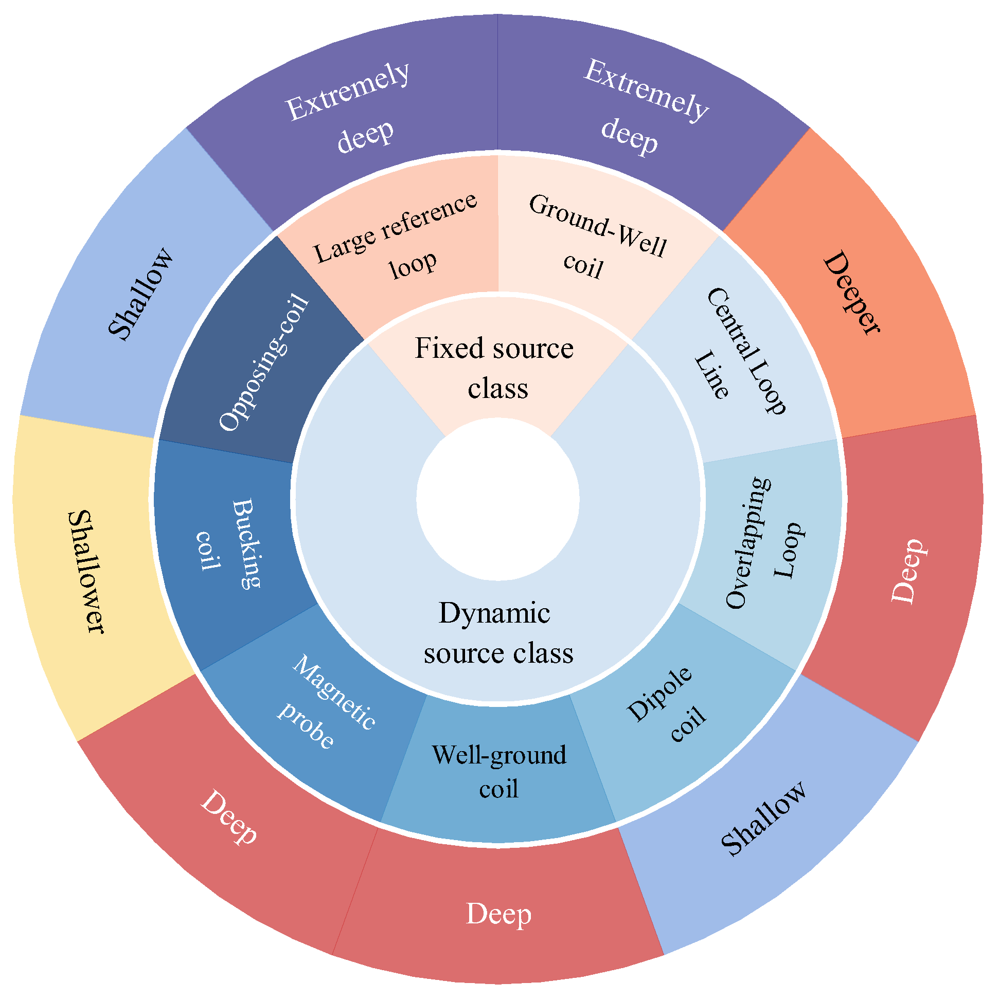
3.1.1. Detection Depth
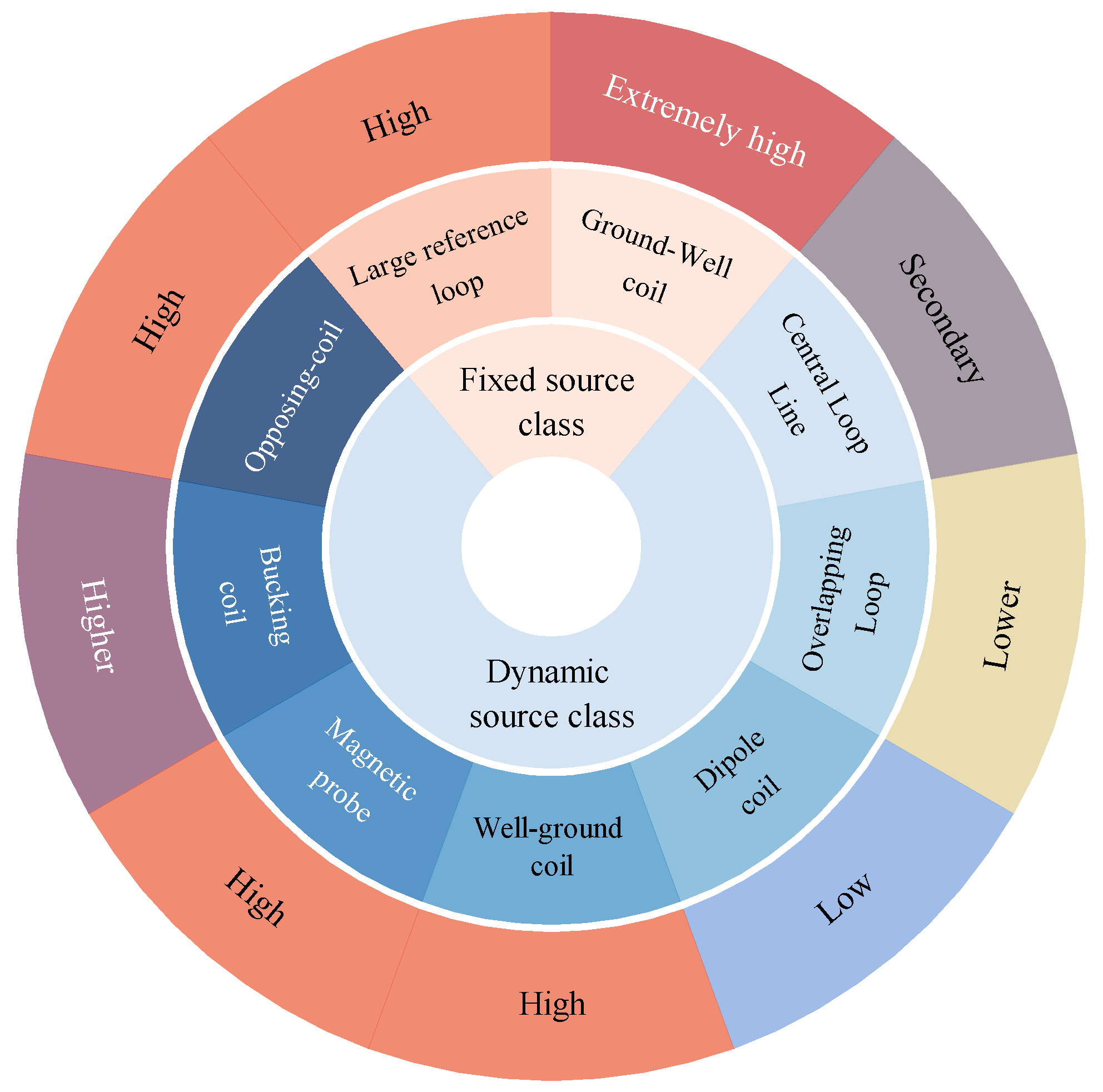
Detection depth is one of the most important indicators in survey work [95]. The detection depth H of coil devices is limited by various conditions, with two key factors being the selection of coil parameters and the resistivity of the overlying layer [96]. The detection depth of coil devices is primarily determined by the resistivity ρ of the overlying layer in the detection area, the magnetic moment M of the coil device, and the minimum discernible voltage η, as shown in Formula (1).
H = 0.55 M ρ 1 η 1 5
From the above equation, it can be seen that increasing the magnetic moment of the coil device or reducing the minimum discernible voltage can enhance the detection depth of the device. The magnetic moment depends on the magnitude of the emission current and the area of the emitting coil.
The specifications for detection depth (maximum detection depth) in this section are provided in Table 2.
For fixed-source devices, the emitting coils can carry large currents and are typically large in size, providing substantial magnetic moments. Among coils of the same size, ground-well devices employ surface emission and tunnel or borehole reception, resulting in the receiving probes being closer to the anomalous body. This proximity enhances the resolution capability for the anomalous body, and thus ground-well devices generally achieve greater detection depths than large fixed-source loops.
In contrast, moving-source devices have significantly smaller emitting coils compared to fixed-source devices, resulting in shallower detection depths. Taking the central loop as a baseline, overlapping loops with coils of the same size can better receive response signals, thereby achieving greater detection depths. Dipole devices, due to the separation between transmitting and receiving coils, have a smaller magnetic field distribution, resulting in smaller magnetic moments compared to central loops, and thus shallower detection depths. Ground-well devices, with multi-turn small-loop emitting coils, have larger magnetic moments and the emitting coils are closer to the target bodies, leading to deeper detection depths. Magnetic probe devices incorporate magnetic cores internally, which better stimulate the electromagnetic field, granting the device a larger magnetic moment, and thus deeper detection depths, compared to central loops. Bucking coils, due to their compensatory design, have larger emission magnetic moments, resulting in greater detection depths. Equivalent reverse magnetic flux coils, with their symmetrical design, completely eliminate primary field interference. However, due to their precise design and smaller emission currents, their detection depth is extremely limited.
In summary, the detection depths of various devices are illustrated in Figure 16.

3.1.2. Resolution

The resolution of a coil device is an indicator of its ability to distinguish and identify different underground geological structures or feature details during the detection process. Resolution is influenced by various factors, including the coil arrangement, noise levels in the detection area, and the excitation method of the emission coil [97,98]. Different coil arrangement methods result in varying coupling responses to target bodies, leading to differences in resolution. The better the coupling effect, the higher the resolution.
The size and shape of coil devices directly impact their resolution. Smaller coil devices can provide higher spatial resolution, allowing for more precise detection of subtle changes in target layers, resulting in higher resolution. Strong noise in the target area can interfere with the response signals at the receiving coil, reducing resolution. Coils with magnetic cores have larger emission magnetic moments, enhancing radial detection resolution.
In addition to the influence of the coils themselves, the arrangement of survey lines and measurement points, as well as data processing methods, significantly affect the resolution of coil devices. Therefore, this section cannot provide precise quantitative specifications for the resolution of coil devices, but can only qualitatively compare the resolution characteristics among different coil devices.
For fixed-source devices, central loops and large fixed-source loops are structurally similar, differing mainly in size. Using the central loop as a baseline, the emission coil can achieve optimal coupling with geological bodies, with minimal volumetric effects and higher resolution. However, the signal intensity of central loops is generally less stable than that of large fixed-source loops. Qualitatively, large fixed-source loops have higher resolution than central loops. Ground-well devices have higher resolution than large fixed-source loops because underground observations can reduce the impact of cover layers on observation effects, with fewer interference factors, resulting in higher resolution and accuracy.
For moving-source devices, overlapping loops have lower resolution than central loops due to greater interference from primary fields. Dipole devices differ from central and overlapping loops in that the centers of the transmitting and receiving coils do not coincide, resulting in smaller responses to target bodies and weaker signals, and thus lower resolution. Ground-well devices, utilizing multi-turn small-loop emission coils, have larger magnetic moments and the emission coils are closer to the target bodies, resulting in higher resolution. Magnetic induction probe devices, with transmitting and receiving coils located within boreholes and in close proximity, can better couple with the magnetic field, thus achieving higher resolution. Bucking coils and equivalent reverse magnetic flux coils can both reduce primary field interference to obtain higher quality response signals. Theoretically, equivalent reverse magnetic flux devices can achieve detection without blind zone.
In summary, the resolutions of various coils are illustrated in Figure 17.

3.1.3. Detection Blind Zone

The detection blind zone of a coil device is an indicator of the survey range. Detection blind zone refers to the shallow area that the device cannot detect. The larger the detection blind zone, the more extensive the shallow area that remains undetected.
Detection blind zone is primarily determined by the inductive effects and cutoff time of the coils [99,100]. In the early stages, strong self-induction signals make it difficult to discern useful signals, thereby creating blind zones. Additionally, mutual inductance between coils prolongs the cutoff time of the coils, increasing the shallow detection blind zone. The magnitude of the current directly affects the detection depth and signal-to-noise ratio, but excessively large currents can also increase the cutoff time of the coils, enlarging the device’s blind zone.
The specifications for detection blind zones (maximum detection blind zone) in this section are provided in Table 3.
For fixed-source devices, large fixed-source loops are sizeable and typically capable of detecting depths of several hundred to even thousands of meters. Their large emission currents result in relatively large blind zones. Ground-well devices, being closer to the target bodies, have smaller blind zones compared to large fixed-source loops.
For moving-source devices, taking the central loop as a baseline, overlapping loops with coils of the same size have significantly larger detection of blind zones due to pronounced inductive effects and prolonged cutoff times. Dipole devices, differing from central and overlapping loops in that the centers of the transmitting and receiving coils do not coincide, exhibit smaller responses to target bodies and weaker signals, resulting in lower resolution. Ground-well devices, utilizing multi-turn small-loop emitting coils, possess stronger mutual inductance, leading to longer cutoff times and larger blind zones. Magnetic probe devices, with transmitting and receiving coils placed within boreholes and in close proximity, can approach target bodies more easily, resulting in smaller blind zones. Bucking coils, with their compensatory design, mitigate inductive effects, resulting in very small blind zones. Equivalent reverse magnetic flux devices can eliminate primary field interference, theoretically achieving zero blind zones.
In summary, the blind zone levels of various coil devices are illustrated in Figure 18.

3.2. Discussion

Different application scenarios and detection requirements have driven the evolution of transient electromagnetic coil devices from the initially simple central loop design to more diverse coil forms. Concurrently, the emergence of new coil forms continues to optimize the application effectiveness of transient electromagnetic methods, providing more options for practical engineering projects.
Given that the same type of coil device is often suitable for multiple application scenarios, this study conducts a comprehensive analysis of each type of coil device across three dimensions: detection depth, resolution, and blind zones. A comprehensive analysis of each coil device type is presented in Table 4.
After undergoing long-term technological evolution, magnetic source transient electromagnetic coil devices have become increasingly diversified and refined in their designs to accommodate different geological environments and detection needs. However, coil devices still face some common issues: there are inductive effects between coils, leading to excessively long shutdown times; coil devices are susceptible to interference from environmental noise signals; due to their high sensitivity to low-resistivity anomalies, metals in the construction environment can also affect transient electromagnetic detection; and for deeper detection tasks, the signal strength and stability of coil devices remain insufficient. Addressing these issues continues to be a trend in the development of transient electromagnetic coils.
Despite these challenges, magnetic source transient electromagnetic coil devices hold significant potential for applications in future underground space development through technological innovation and structural optimization, promising to provide more precise and efficient solutions in the field of geophysical exploration. The application of magnetic source TEM devices will become more widespread, with development trends focusing on the following three aspects.
The first aspect is multifunctionality. Future detection devices will possess multiple detection functions, integrating various types of coils to combine different detection capabilities tailored to diverse engineering environments. Devices will also incorporate data analysis functions, processing information concurrently with data collection to provide more accurate analyses of underground structural data. Additionally, future advancements will enhance the noise interference resistance of magnetic source devices, improving their adaptability to complex environments.
The second aspect is automation. Future detection devices will achieve intelligent recognition and extraction of electromagnetic signals, accurately identifying the response signals of target geological bodies to obtain precise geological information. Coil devices will also be integrated with imaging systems, automatically processing and imaging data while acquiring geological information, making detection work more convenient and efficient.
The third aspect is intelligence. Future detection devices will integrate with artificial intelligence tools such as drones and unmanned vehicles, mounting detection coils on unmanned platforms. Through information control systems, these devices will be remotely operated in real-time, capable of obtaining accurate information in extreme geological conditions, such as underground abandoned spaces, high-temperature and high-pressure environments, and forests, which are areas difficult for humans to access.
With the advancement of artificial intelligence technology, remote detection will be realized, enhancing detection efficiency and accuracy. Coil devices will also integrate more functions to meet the diverse detection needs in complex environments, thereby reducing the limitations of single-function applications. Furthermore, improving coil structural design and enhancing manufacturing processes will further elevate coil performance, optimizing their applicability and detection effectiveness under different geological conditions. In the future, magnetic source transient electromagnetic detection devices will evolve towards greater depth measurement, higher (lateral) resolution, non-contact coupling, and efficient detection, holding infinite possibilities for TEM in the field of geophysical exploration.

4. Conclusions

This study summarizes the working principles and application scenarios of various magnetic source transient electromagnetic coil devices and analyzes the characteristics of different devices. The conclusions are as follows:
(1)
The TEM coil devices are categorized into fixed source devices and mobile source devices based on whether the transmitter is stationary. Fixed source devices typically offer higher resolution and greater detection depth. Mobile source devices exhibit strong environmental adaptability, are easy to transport and operate, and are effective in acquiring abundant geological information.
(2)
Fixed-source TEM devices are typically larger in size and possess strong emission currents, enabling substantial detection depths and high resolution. However, these devices are cumbersome to install, have low construction efficiency, provide limited data, and incur higher costs. In contrast, moving-source devices are generally smaller, easier, and quicker to install, with weaker emission currents and limited detection depth.
(3)
Large fixed-source loops and well-ground devices utilize substantial emission coils to generate strong magnetic fields. Central loops, with their simple structure, facilitate optimal coupling with targets. Overlapping loops possess larger emission and reception magnetic moments. Dipole devices have been largely replaced by newer technologies. Well-ground devices employ multi-turn small loops for emission coils, providing large magnetic moments and extensive receiving units for deep detection. Magnetic induction probes effectively address the “one-hole view” limitation in borehole detection. Bucking coils and equivalent reverse magnetic flux devices reduce primary field interference to obtain higher quality response signals, with the latter theoretically eliminating detection blind zones.

Author Contributions

This paper was jointly completed by Y.Y., F.Y., B.W., W.Q., Y.W. and Y.Z.; writing—original draft, Y.Y. and F.Y.; funding acquisition, B.W.; writing—review and editing, W.Q., Y.W. and Y.Z.; investigating and organizing references, Y.Y., F.Y., Y.W. and Y.Z. All authors reviewed and provided revisions to the paper. All authors have read and agreed to the published version of the manuscript.

Funding

The research was funded by the National Natural Science Foundation of China (No. 42404148, No. 52208395, No. 42174165), the Natural Science Foundation of Jiangsu Province (No. BK20230197) and the National College Student Innovation and Entrepreneurship Training Program of China University of Mining and Technology (No. 202410290015Z).

Data Availability Statement

Not applicable.

Conflicts of Interest

The authors declare no conflicts of interest.

References

  1. Xue, G.Q.; Li, X.; Di, Q.Y. The progress of TEM in theory and application. Prog. Geophys. 2007, 22, 1195–1200. [Google Scholar]
  2. Farquharson, C.G.; Hu, X.; Huang, Q.; Li, X.; Li, J.; Xue, G.; Yin, C. Advances in Transient Electromagnetic Methods. J. Geophys. Eng. 2023, 20, 1305–1307. [Google Scholar] [CrossRef]
  3. Kassie, L.N.; Chang, P.-Y.; Zeng, J.-R.; Huang, H.-H.; Chen, C.-S.; Doyoro, Y.G.; Lin, D.-J.; Puntu, J.M.; Amania, H.H. Mapping Hydrogeological Structures Using Transient Electromagnetic Method: A Case Study of the Choushui River Alluvial Fan in Yunlin, Taiwan. Water 2023, 15, 1703. [Google Scholar] [CrossRef]
  4. Feng, Q.; Li, C.; Hao, S.; Li, D.; Liu, T.; Sun, Z.; Zhou, L. Hydrogeological Investigation of a Goaf and Subsidence Area Based on a Ground-to-Air Transient Electromagnetic Sounding Method. Water 2024, 16, 1067. [Google Scholar] [CrossRef]
  5. Lu, Y.; Tao, J.; Cao, C.; Liu, H.; Liu, Y.; Ge, Z. Detection of Landfill Leachate Leakage Based on ERT and OCTEM. Water 2023, 15, 1778. [Google Scholar] [CrossRef]
  6. Lu, T.; Liu, H.; Jia, H.; Wang, B. A Geophysical-Drilling-Hydrochemical Coupled Method for Accurate Detection of Concealed Water-Conducting Faults in Coal Mines. Water 2024, 16, 2619. [Google Scholar] [CrossRef]
  7. Li, K.; Sun, H.F.; Su, C.X.; Li, S.C.; Tang, P.Y.; Qi, Z.P. Comparison of transient electromagnetic configuration in prediction of water bearing structures in tunnels. Chin. J. Rock Mech. Eng. 2017, 36, 3164–3173. [Google Scholar]
  8. Zhang, Y.Y.; Li, X. Research progress on ground-airborne transient electromagnetic method. Prog. Geophys. 2017, 32, 1735–1741. [Google Scholar] [CrossRef]
  9. Lin, J.; Wang, L.; Wang, X.G.; Cai, M.; Fu, L.; Shang, X.L. Research and development on the air-core coil sensor for mine transient electromagnetic exploration. Chin. J. Geophys. 2016, 59, 721–730. [Google Scholar] [CrossRef]
  10. Wang, L.; Zhang, S.; Chen, S.; Jiang, H. Fast Localization of Underground Targets by Magnetic Gradient Tensor and Gaussian-Newton Algorithm with a Portable Transient Electromagnetic System. IEEE Access 2021, 9, 148469–148478. [Google Scholar] [CrossRef]
  11. Jiang, Z.; Liu, S.; Malekian, R. Analysis of a Whole-Space Transient Electromagnetic Field in 2.5-Dimensional FDTD Geoelectric Modeling. IEEE Access 2017, 5, 18707–18714. [Google Scholar] [CrossRef]
  12. Yang, H.; Chen, S.; Yue, J.; Li, F.; Zhang, H. Transient Electromagnetic Response with a Ramp Current Excitation Using Conical Source. IEEE Access 2019, 7, 63829–63836. [Google Scholar] [CrossRef]
  13. Barsukov, P.O.; Fainberg, E.B. Mapping Bedrock Topography and Moraine Deposits by Transient Electromagnetic Sounding: Oslo Graben, Norway. Near Surf. Geophys. 2020, 18, 123–133. [Google Scholar] [CrossRef]
  14. QI, Z.; Li, X.; Zhu, H.W.; Ma, B.-z.; Zhang, J.; Wu, Q. Definition of apparent resistivity for non-center vertical component of Large-loop TEM configuration. Prog. Geophys. 2011, 26, 1350–1358. [Google Scholar]
  15. Han, Z.Q.; Liu, T.; Ou, Y.J.; Luo, J. Application of large rectangular loop source TEM all-time apparent resistivity on colliery goaf exploration. Prog. Geophys. 2015, 30, 343–349. [Google Scholar] [CrossRef]
  16. Pan, J.S.; Zhang, X.; Chen, S.Z.; Zhang, J.L.; Zhang, Y.T. Application of transient electromagnetic method with large fixed source loop device in detection of coal mine goaf. Technol. Innov. Appl. 2024, 14, 137–140. [Google Scholar] [CrossRef]
  17. Bai, J.; Yao, J.; Yang, Z.; Guo, Y.; Wang, L. Transient Electromagnetic Weak Signal Extraction Method Based on Multi-Scale Combined Difference Product Morphological Filtering. IEEE Access 2022, 10, 22140–22149. [Google Scholar] [CrossRef]
  18. Wu, X.; Pan, D.M.; Yu, J.C. Review in the geophysical methods for coalmine goaf prospecting. Prog. Geophys. 2022, 37, 1197–1206. [Google Scholar] [CrossRef]
  19. Xue, G.Q.; Li, H.; Chen, W.Y.; Yu, C.T.; Chang, J.H.; Yu, J.C. Progress of transient electromagnetic detection technology for water-bearing bodies in coal mines. J. China Coal Soc. 2021, 46, 77–85. [Google Scholar]
  20. Su, B.Y.; Yu, J.C.; Wang, Y.Z.; Tang, Y.; Yang, H.Y.; Li, M.F.; Li, H.H.; Sun, S.Y. Characteristics and application of ground-borehole transient electromagnetic response to coal seam roof separated layer water. J. Min. Saf. Eng. 2023, 40, 572–577. [Google Scholar]
  21. Sun, H.F.; Zhang, Y.Y.; Zhao, Y.C.; Liu, Y.C.; Zhao, H.L. Present study situation review of borehole transient electromagnetic method. Coal Geol. Explor. 2022, 50, 85–97. [Google Scholar]
  22. Boyd, G.W.; Wiles, C.J. The Newmont Drill-hole EMP System—Examples from Eastern Australia. Geophysics 1984, 49, 949–956. [Google Scholar] [CrossRef]
  23. Bishop, J.R.; Lewis, R.J.G.; Macnae, J.C. Down-Hole Electromagnetic Surveys at Renison Bell, Tasmania. Explor. Geophys. 1987, 18, 265–277. [Google Scholar] [CrossRef]
  24. Zhang, J.; Deng, X.H.; Guo, X.; Wu, J.J.; Wang, X.C. Typical cases of applying borehole tem to deep prospecting in crisis mines. Geophys. Geochem. Explor. 2013, 37, 30–34. [Google Scholar]
  25. Zhang, J.Z.; Hu, F.H.; Liu, H.X.; Xing, G.Z. TEM response characteristics of borehole in goaves of old coal mines. Geophys. Geochem. Explor. 2022, 46, 191–197. [Google Scholar] [CrossRef]
  26. Song, F. Study on Forward and Inversion of Transient Electromagnetic Method for Central Loop Devices. Master’s Thesis, Chongqing University, Chongqing, China, 2018. [Google Scholar]
  27. Chen, X.H. Study About 1D Forward and Inversion Algorithm of Central-Loop TEM Data. Master’s Thesis, Chengdu University of Technology, Chengdu, China, 2012. [Google Scholar]
  28. Xian, Y.; Lan, R.; Liu, Y.; Li, D.; Yang, J.; Sun, H. Improved Adaptive Thin-Layer Inversion for Semi-Airborne Transient Electromagnetic Method. J. Geophys. Eng. 2023, 20, 915–926. [Google Scholar] [CrossRef]
  29. Yan, S.; Chen, M.S.; Shi, X.X. Transient Electromagnetic Sounding Using a 5 m Square Loop. Explor. Geophys. 2009, 40, 193–196. [Google Scholar] [CrossRef]
  30. Wang, S.X.; Liu, J.; Lei, Z. The relationship between the loop size and the optimal detecting depth in in-loop TEM. Comput. Tech. Geophys. Geochem. Explor. 2012, 34, 548–551. [Google Scholar]
  31. Liu, C.S.; Lin, J.; Zhou, F.D. Transient response characteristics of central loop configuration on seafloor. Chin. J. Radio Sci. 2010, 25, 195–200. [Google Scholar]
  32. Vrbancich, J. Airborne Electromagnetic Bathymetry Investigations in Port Lincoln, South Australia—Comparison with an Equivalent Floating Transient Electromagnetic System. Explor. Geophys. 2011, 42, 167–175. [Google Scholar] [CrossRef]
  33. Li, Z.G. Application of Central Loop Transient Electromagnetic Method in an Underground Tunnel Exploration. Site Investig. Sci. Technol. 2019, 4, 55–57. [Google Scholar]
  34. Guo, S.W.; Yan, Q. Application of Transient Electromagnetic Methods in Water Exploration of the West of Ming’an Town in Wulateqianqi, Inner Mongolia. Sci. Technol. Eng. 2020, 20, 2564–2572. [Google Scholar]
  35. Zhao, H.; Wang, H.; Zhou, X.G. Application of TEM in Detecting Goaf of Shallow Coal Seam. Mod. Chem. Res. 2023, 18, 125–127. [Google Scholar]
  36. Jiang, Z.H.; Yue, J.H.; Liu, S.C. Mine transient electromagnetic observation system of small multi-turn coincident configuration. J. China Coal Soc. 2007, 32, 1152–1156. [Google Scholar]
  37. Liu, T. Application of small-wireframe overlapping loop TEM in geological exploration. New Tech. Prod. China 2024, 4, 114–116. [Google Scholar]
  38. Spies, B.R. The Dual Loop Configuration of the Transient Electromagnetic Method. Geophysics 1975, 40, 1051–1057. [Google Scholar] [CrossRef]
  39. Cheng, K. Inversion Methods and Experimental Study of Fixed-loop Transient Electromagnetic in Tunnels. Master’s Thesis, Shandong University, Jinan, China, 2022. [Google Scholar]
  40. Liu, J.P.; Che, H.Q.; Zhu, H.; Liu, F.; Sun, Y. Transient Electromagnetic Response for a Coincident Loop in a Full-space Layered Medium. Sci. Technol. Ind. 2023, 23, 289–295. [Google Scholar]
  41. Yang, H.Y.; Wu, X.M.; Zhang, H. Delay Correction Technique of Underground Transient Electromagnetic Method with Coincident Loop. J. East China Univ. Technol., Nat. Sci. 2016, 39, 362–368. [Google Scholar]
  42. Maurya, P.K.; Christiansen, A.V.; Pedersen, J.; Auken, E. High Resolution 3D Subsurface Mapping Using a Towed Transient Electromagnetic System—tTEM: Case Studies. Near Surf. Geophys. 2020, 18, 249–259. [Google Scholar] [CrossRef]
  43. Ma, S.D. Research on Zero Mutual Inductance Overlapping Loop Transient Electromagnetic Method. Master’s Thesis, Zhejiang University, Hanzhou, China, 2019. [Google Scholar]
  44. Zhuang, D.Y. Application of Overlap Loop Transient Electromagnetic Method in Goaf Exploration. China Plant Eng. 2021, 2, 135–137. [Google Scholar]
  45. Guo, R.P.; Zhang, K.; Tian, J.H.; Cheng, B.; Zhang, H.T. Small Multi-turn Coincident with Large Current Transient Electromagnetics Method Application Effect in Geotechnical Engineering Investigation. Chin. J. Eng. Geophys. 2021, 18, 503–512. [Google Scholar]
  46. Ying, Y. Transient Electromagnetic Structure Radar Research. Adv. Geosci. 2019, 9, 218–229. [Google Scholar] [CrossRef]
  47. Liu, C.S.; Lin, J.; Ji, Y.J.; Wu, G.Q. On model experiments of TEM dipole configuration. Geophys. Geochem. Explor. 2006, 30, 430–434. [Google Scholar]
  48. Jiao, J.M. Physical Simulation and Application of TEM Dipole Device on Concealed Water Source in Coal Mine. Master’s Thesis, China University of Mining and Technology, Xuzhou, China, 2018. [Google Scholar]
  49. Chen, G. Ability of dipole devices to reflect IP anomalies. Geophys. Geochem. Explor. 1986, 10, 398–400. [Google Scholar]
  50. Xue, G.Q.; Yan, S.; Zhou, N.N. Theoretical study on the errors caused by dipole hypothesis of large-loop TEM response. Chin. J. Geophys. 2011, 54, 2389–2396. [Google Scholar]
  51. Maher, M.J. Transient Electromagnetic Surveys in the Okiep District. Geophysics 1992, 57, 736–744. [Google Scholar] [CrossRef]
  52. Li, H.Y.; Zhao, Y.H. Application effect and improvement of technology of coal mine dipole transient electromagnetic. China Coal 2014, 40, 37–39+72. [Google Scholar] [CrossRef]
  53. Liu, X.F.; Wu, G.R.; Zhang, T.; Guo, L.C. On application of NanoTEM in detection of troubles in canal banks. Shanxi Archit. 2016, 42, 223–224. [Google Scholar] [CrossRef]
  54. Shi, C.H.; Liu, L.D.; Jia, X.Y. Advanced Geological Prediction Method and Application of TEM Based on Coaxial Dipole Device. Chin. J. Eng. Geophys. 2021, 18, 579–588. [Google Scholar] [CrossRef]
  55. Wang, P. Study on floating coefficient space intersection and equivalent current loop inversion of Downhole TEM. Ph.D. Thesis, China University of Geosciences, Wuhan, China, 2017. [Google Scholar]
  56. Yang, Y.; Dang, R.R.; Ren, Z.P. Research on transient electromagnetic method in borehole. Pet. Instr. 2009, 23, 99. [Google Scholar]
  57. Wu, Q.; Zhi, Q.Q.; Wu, J.J.; Wang, X.C. Study on the approximation between equivalent current field and pure anomaly field of borehole-ground joint transient electromagnetic method. Comput. Tech. Geophys. Geochem. Explor. 2022, 44, 224–234. [Google Scholar]
  58. Yang, H.Y.; Yue, J.H.; Liu, Z.X. Theoretical Study of Inductance Effect With Multi-axial Coils for TEM in Underground Mine. J. Jilin Univ. Earth Sci. Ed. 2006, 36, 168–171. [Google Scholar]
  59. Ren, Z.; Kalscheuer, T. Uncertainty and Resolution Analysis of 2D and 3D Inversion Models Computed from Geophysical Electromagnetic Data. Surv. Geophys. 2020, 41, 47–112. [Google Scholar] [CrossRef]
  60. Wang, P.; Li, M.; Yao, W.; Su, C.; Wang, Y.; Wang, Q. Detection of Abandoned Water-Filled Mine Tunnels Using the Downhole Transient Electromagnetic Method. Explor. Geophys. 2020, 51, 667–682. [Google Scholar] [CrossRef]
  61. Shi, H. Application of comprehensive geophysical prospecting methods in groundwater exploration in thick overburden areas. Hydrogeol. Eng. Geol. 2005, 32, 101–104. [Google Scholar]
  62. Wu, J.J.; Liu, B.; Zhi, Q.Q.; Deng, X.H.; Wang, X.C.; Yang, Y.; Liu, D.M.; Qiu, J.Z. Application of surface and borehole TEM joint exploration in 2000 m deep mineral exploration. Coal Geol. Explor. 2022, 50, 70–78. [Google Scholar]
  63. Shao, Y.Q.; Cheng, D.F.; Wang, Y.Z.; Zhang, F. Research of high sensitivity inductive magnetic sensor. Chin. J. Sci. Instrum. 2012, 33, 349–355. [Google Scholar]
  64. Vallianatos, F. A Non Extensive View of Electrical Resistivity Spatial Distribution Estimated Using Inverted Transient Electromagnetic Responses in a Karstified Formation (Keritis Basin, Crete, Greece). Physica A 2018, 505, 171–178. [Google Scholar] [CrossRef]
  65. Simard, P.T.; Chesnaux, R.; Rouleau, A.; Daigneault, R.; Cousineau, P.A.; Roy, D.W.; Lambert, M.; Poirier, B.; Poignant-Molina, L. Imaging Quaternary Glacial Deposits and Basement Topography Using the Transient Electromagnetic Method for Modeling Aquifer Environments. J. Appl. Geophy. 2015, 119, 36–50. [Google Scholar] [CrossRef]
  66. Wang, K.B. Research of mining induction probe of TEM detection system. J. Xi’an Univ. Sci. Technol. 2013, 33, 336–342. [Google Scholar]
  67. Fan, T.; Zhao, Z.; Wu, H.; Lu, J.J.; Wang, J.K. Research on inductance effect removing and curve offset for mine TEM with multi small loops. J. China Coal Soc. 2014, 39, 932–940. [Google Scholar]
  68. Fan, T. Experimental study on the exploration of coal mine goaf by dynamic source and fixed reception Roadway-Borehole TEM detection method. J. China Coal Soc. 2017, 42, 3229–3238. [Google Scholar]
  69. Xiao, P.; Shi, Z.; Wu, X.; Fang, G. Improved Bucking Coil Design in Helicopter Transient Electromagnetic System. Prog. Electromagn. Res. M 2017, 60, 131–139. [Google Scholar] [CrossRef]
  70. Chen, J.; Pi, S.; Zhang, Y.; Lin, T. Weak Coupling Technology with Noncoplanar Bucking Coil in a Small-Loop Transient Electromagnetic System. IEEE Trans. Ind. Electron. 2022, 69, 3151–3160. [Google Scholar] [CrossRef]
  71. Witherly, K.; Witherly, K. Mapping Targets of High Conductance with the VTEM Airborne EM System. ASEG Ext. Abstr. 2007, 2007, 1–4. [Google Scholar] [CrossRef]
  72. Kuzmin, P.V.; Morrison, E.B. Bucking Coil and B-Field Measurement System and Apparatus for Time Domain Electromagnetic Measurements. U.S. Patent 8,400,157, 19 March 2013. [Google Scholar]
  73. Liang, Q.H. The Technology and Application of Mine Full-Space Transient Electromagnetic Detection by Small Coil. Ph.D. Thesis, Central South University, Changsha, China, 2012. [Google Scholar]
  74. Jiang, J. Application of Towed TEM Method in Shallow Waters Geotechnical Investigation. Coal Geol. China 2019, 31, 103–107. [Google Scholar]
  75. Long, X.; Xi, Z.Z.; Zhou, S.; Hou, H.T.; Wang, L.; Xue, J.P. Detection capability of opposing coils transient electromagnetic method for thin layers. Prog. Geophys. 2020, 35, 753–759. [Google Scholar] [CrossRef]
  76. Wang, Y.; Xi, Z.Z.; Jiang, H.; Hou, H.T.; Zhou, S.; Fan, F.L. The application research on the detection of karst disease of airport runway based on OCTEM. Geophys. Geochem. Explor. 2017, 41, 360–363. [Google Scholar] [CrossRef]
  77. Fan, X.Y. Development and Application of Self-balancing Opposing Coils Transient Electromagnetics Instrument. Master’s Thesis, South-Central University for Nationalities, Wuhan, China, 2021. [Google Scholar]
  78. Zhao, S.W. Application of shallow TEM in the exploration of water filled karst cave in southwest Custer area. Railw. Investig. Surv. 2017, 43, 102–105. [Google Scholar]
  79. Zhou, L.; Cao, C.H.; Deng, Z.; Tan, J.L.; Long, X. Case Study of Geophysical Prospecting Water under the Condition of Limited Site in Urban Areas. Urban Geol. 2019, 14, 97–102. [Google Scholar]
  80. Zhou, C.; Qiao, H.Q.; Zhao, S.W.; Zhao, W.L. Application of shallow transient electromagnetic method in concealed fault exploration of subway project. Geotech. Investig. Survey. 2018, 46, 74–78. [Google Scholar]
  81. He, Y. Application of high-density electrical method and equivalent reverse flux transient electromagnetic method in exploration of a certain mining area. China Metal Bull. 2019, 6, 201–202. [Google Scholar]
  82. Wang, T.T.; Wang, Y.; Ren, J.; Zhang, Z.H. Application of equivalent inverse flux transient electromagnetic method in the detection of leakage hidden danger of the Yangtze River dike. Jiangsu Water Res. 2024, 2, 58–62. [Google Scholar]
  83. Kang, F.P.; Deng, Y.; Cao, C.H.; Jing, J.; Liu, C.M.; Peng, J.; Zhou, L. Application of Opposing Coils Transient Electromagnetic Method in Leakage Detection of Urban Domestic Waste Landfills. Chin. J. Eng. Geophys. 2023, 20, 725–732. [Google Scholar]
  84. Zhao, D.D.; Chen, J.W.; Zong, Q.B.; Zhang, B.D.; Di, B.Y.; Zhu, H.B.; Wang, J.L. Application of Opposing Coils Transient Electromagnetic Method in Metro Shielding Boulder Detection. Chin. J. Eng. Geophys. 2021, 18, 495–502. [Google Scholar]
  85. Liu, J.X. Application of Equivalent Reverse Flux Transient Electromagnetic Method to Underwater Detection. Chin. J. Eng. Geophys. 2019, 16, 764–769. [Google Scholar]
  86. Lin, J.; Chen, J.; Liu, F.; Zhang, Y. The Helicopter Time-Domain Electromagnetic Technology Advances in China. Surv. Geophys. 2021, 42, 585–624. [Google Scholar] [CrossRef]
  87. Yan, L. Advancements in Controlled Source Electromagnetic Methods for Prospecting Unconventional Hydrocarbon Resources in China. Surv. Geophys. 2024, 45, 239–276. [Google Scholar] [CrossRef]
  88. Bai, Y.; Zhang, J.; Zhang, M.; Rao, W. Flexible Liquid Metal Electromagnetic Shielding Materials. Sci. China Technol. Sci. 2023, 66, 2757–2774. [Google Scholar] [CrossRef]
  89. Li, G.C.; Xu, Y.K.; Zhao, Z.T.; Wang, Y.; Hu, J. Simulation and Analysis of 8-shaped Coils Structure for Electromagnetic Transmitter Based on MAXWELL. Sci. Technol. Eng. 2013, 13, 10481–10484, 10500. [Google Scholar]
  90. Xie, S.W.; Yang, H.Y.; Liu, S.G.; Xu, Z.Y.; Dong, M.M.; Deng, J.Z.; Zhang, H.; Tang, H.Z. The comparative with single loop and the loop of type 8 of transient electromagnetic method. Prog. Geophys. 2015, 30, 1354–1360. [Google Scholar] [CrossRef]
  91. Yang, H.Y.; Li, F.P.; Yue, J.H.; Liu, X.H.; Zhao, H.J. Optimal transient electromagnetic inversionof conical field source based on smoke ring theory. J. China Univ. Min. Technol. 2016, 45, 1230–1237. [Google Scholar]
  92. Yang, H.Y.; Li, F.P.; Yue, J.H.; Guo, F.S.; Liu, X.H.; Zhang, H. Cone-shaped source characteristics and inductance effect of transient electromagnetic method. Appl. Geophys. 2017, 14, 165–174, 192. [Google Scholar] [CrossRef]
  93. Yang, H.Y.; Liu, Z.X.; Zhang, H.; Chen, X.; Li, Z.; Wang, L.; Yang, F.J. Experimental study on transient electromagnetic method with a conical source. Coal Geol. Explor. 2021, 49, 107–112. [Google Scholar]
  94. Hu, X.W.; Chen, R.J.; Zhang, P.S.; Wu, R.C.; Fu, M.R.; Zhou, H.Y. Development and experiment of transient electromagnetic common centerzero-flux coil. J. China Coal Soc. 2023, 48, 918–930. [Google Scholar]
  95. Zhang, Z.; Liu, S. Two-Dimensional Whole Space Transient Electromagnetic Forward Response of Magnetic Moment in Arbitrary Direction. IEEE Access 2021, 9, 82462–82470. [Google Scholar] [CrossRef]
  96. Chang, J.; Yu, J.; Li, J.; Xue, G.; Malekian, R.; Su, B. Diffusion Law of Whole-Space Transient Electromagnetic Field Generated by the Underground Magnetic Source and Its Application. IEEE Access 2019, 7, 63415–63425. [Google Scholar] [CrossRef]
  97. Ji, Y.; Li, D.; Yuan, G.; Lin, J.; Du, S.; Xie, L.; Wang, Y. Noise Reduction of Time Domain Electromagnetic Data: Application of a Combined Wavelet Denoising Method. Radio Sci. 2016, 51, 680–689. [Google Scholar] [CrossRef]
  98. Xue, G.Q.; Yan, Y.J.; Li, X.; Di, Q.Y. Transient Electromagnetic S-Inversion in Tunnel Prediction. Geophys. Res. Lett. 2007, 34, L18403. [Google Scholar] [CrossRef]
  99. Xue, G.Q.; Yan, Y.J.; Li, X. Pseudo-Seismic Wavelet Transformation of Transient Electromagnetic Response in Engineering Geology Exploration. Geophys. Res. Lett. 2007, 34, L16405. [Google Scholar] [CrossRef]
  100. Moorkamp, M. Integrating Electromagnetic Data with Other Geophysical Observations for Enhanced Imaging of the Earth: A Tutorial and Review. Surv. Geophys. 2017, 38, 935–962. [Google Scholar] [CrossRef]
Figure 1. Receiving coil located inside the return line.
Water 17 00171 g001
Figure 2. Receiving coil located outside the return line.
Water 17 00171 g002
Figure 3. Ground well TEM device.
Water 17 00171 g003
Figure 4. The central loop.
Water 17 00171 g004
Figure 5. The overlapping loop.
Water 17 00171 g005
Figure 6. Coplanar dipole coil.
Water 17 00171 g006
Figure 7. Coaxial dipole coil.
Water 17 00171 g007
Figure 8. The well-ground TEM.
Water 17 00171 g008
Figure 9. Magnetic induction probe.
Water 17 00171 g009
Figure 10. Coplanar bucking coil.
Water 17 00171 g010
Figure 11. Non-coplanar bucking coil.
Water 17 00171 g011
Figure 12. The opposing coils.
Water 17 00171 g012
Figure 13. “8”-shaped transmitter coil.
Water 17 00171 g013
Figure 14. Conical field source coil.
Water 17 00171 g014
Figure 15. Co-centered zero magnetic flux coil.
Water 17 00171 g015
Figure 16. Comparison diagram of detection depth of each coil device.
Water 17 00171 g016
Figure 17. Resolution comparison of various coil devices.
Water 17 00171 g017
Figure 18. Comparison diagram of blind zones detected by various coil devices.
Water 17 00171 g018
Table 1. Transient electromagnetic coil classification table.
Device ClassificationMeaningCoil StructureAdvantagesDisadvantagesApplication
Fixed-source devicesFixed source locationThe large fixed-source loop, the ground-hole TEMHigh resolution and deep detection depth, facilitating detailed geological structure analysis in specific areasInconvenient construction, low construction efficiency, and high costsOil exploration, detection of deep hidden mineral deposits and goaf areas
Dynamic source devicesFlexible source locationThe central loop method, the transient electromagnetic dipole device, the well-ground TEM, magnetic induction probes, bucking coils, the opposing coils, and othersMeeting diverse detection requirements, adapting to various environmental conditions, facilitating portability and operation, and enabling the acquisition of abundant geological informationConvenient construction, high construction efficiency, and rich dataEngineering surveys, hydrological surveys, advance detection in mine shafts and shallow coal seam goaf
Table 2. Maximum depth specification.
Detection Depth MetricSpecified Range
Extremely deep>2000 m
Deep200~2000 m
Deeper100~200 m
Shallower50~100 m
Shallow<50 m
Table 3. Maximum detection blind zone specification.
Detection Blind Zone MetricSpecified Range
Very large>200 m
Large150~200 m
Relatively large100~150 m
Medium50~100 m
Relatively small30~50 m
Small10~30 m
Very small<10 m
Table 4. Comprehensive analysis of various types of coils.
Device ClassificationDetection DepthResolutionDetection Blind Zone
The large fixed-source loopExtremely deepHighLarge
The ground-hole TEMExtremely deepExtremely highVery large
The central loop methodDeeperMediumMedium
Overlapping CoilsDeepLowerRelatively large
The transient electromagnetic dipole deviceShallowLowSmall
The well-ground TEMDeepHighRelatively large
Magnetic induction probesDeepHighRelatively small
Bucking coilsShallowerHigherVery small
The opposing coilsShallowHighVery small
Disclaimer/Publisher’s Note: The statements, opinions and data contained in all publications are solely those of the individual author(s) and contributor(s) and not of MDPI and/or the editor(s). MDPI and/or the editor(s) disclaim responsibility for any injury to people or property resulting from any ideas, methods, instructions or products referred to in the content.

