Article

Failure Characteristics and Stress Distribution of Intact Floor Under Coupled Static and Dynamic Loads in Mining Projects

1
Sinosteel Maanshan General Institute of Mining Research Co., Ltd., Maanshan 243000, China
2
School of Civil Engineering and Architecture, Anhui University of Technology, Maanshan 243032, China
3
College of Geoscience and Surveying Engineering, China University of Mining and Technology (Beijing), Beijing 100083, China
4
State Key Laboratory of Safety and Health for Metal Mines, Maanshan 243000, China
*
Authors to whom correspondence should be addressed.
Water 2025, 17(5), 699; https://doi.org/10.3390/w17050699
Submission received: 19 January 2025 / Revised: 18 February 2025 / Accepted: 25 February 2025 / Published: 27 February 2025
(This article belongs to the Special Issue Engineering Hydrogeology Research Related to Mining Activities)

Abstract

:
Numerous floor water inrush (FWI) disasters have occurred during the roof weighting period in China. Therefore, to clarify why FWI accidents tend to cluster at a specific mining stage, a novel method for evaluating the failure depth of mining floors (FDMF) under dynamic loads induced by roof breakage is proposed in this study. By employing Matlab programming, the stress distribution and failure patterns of the intact floor were analyzed, revealing the dynamic stress response and failure characteristics. In addition, the accuracy of the proposed theoretical model was further verified through numerical simulation and field measurement. The results indicate that dynamic loads significantly impact vertical stress and shear stress, but only have a minor impact on horizontal stress. This leads to an expansion of the stress concentration zone and an increase in the intensity of the mining floor. Moreover, the FDMF is notably enhanced under the dynamic load induced by roof weighting. Besides, both the numerical simulations and field measurement results align closely with the theoretical predictions, which confirm the effectiveness of the proposed method. This study provides a theoretical foundation for understanding FWI mechanisms under the combined influence of dynamic and static loads.

1. Introduction

Most mining regions in China will transition to deep mining as a result of the ongoing depletion of shallow coal deposits and continued increases in mineral consumption. In deep mining environments, FWI accidents are often triggered by the high water pressure of Ordovician limestone formations, a major aquifer, and pose significant water inrush risks during mining in the North China coalfields [1]. Statistically, more than 60% of FWI accidents happen during the periods of first and roof periodic weighting at the working face [2,3]. Some typical FWI accidents are listed in Table 1. The explanation for these accident regularities can be obtained by analyzing the stress conditions of the mining floor. First, the abutment pressure on the floor induced by mining activities peaks prior to the roof weighting. Furthermore, during these periods, the floor is subjected to extra dynamic loads induced by roof breakage, leading to enhanced disturbance and an increase in FDMF [4,5]. The schematic of loading is shown in Figure 1.
Moreover, owing to the high in situ stress within deep rock masses at significant depths, the floor stratum has a more visible stress concentration and is more susceptible to the dynamic load disturbance reaction because of the strong mining pressure [13]. In recent years, the frequency of FWI accidents triggered by mining-induced dynamic stress has escalated [14,15]. Therefore, it is still a pressing scientific issue to properly explain the evolution process of the water inrush channel in the coal mine floor, particularly the influence mechanism of dynamic load disturbance on the stress distribution, damage laws, and failure characteristics of the mining floor. As a result, it is significant to investigate the mechanical behaviors and failure characteristics of mining floors affected by coupled static-dynamic loading.
Understanding the stress distribution and failure characteristics of coal mine floors is fundamental to elucidating the mechanism of FWI. Numerous studies have explored the failure mechanisms of coal seam floors through theoretical calculations [14,16,17,18,19,20,21], numerical simulation [22,23,24,25,26], physical model tests, and in situ measurements [27,28,29,30,31]. Some studies have pointed out that FWI is related to the dynamic load of the main roof. Through the analysis of the spatial and temporal relationship between the mining stress and the response of water pressure, it is inferred that floor water inrush in deep mining is related to the strong dynamic load caused by the roof collapse [32]. With regard to the failure mechanism of floors caused by dynamic load, scholars derived the relationship model between the intensity of dynamic load and FDMF by applying the elasticity theory [33]. Additionally, on-site continuous monitoring of FDMF was carried out, and the phenomenon of floor secondary damage by dynamic disturbances generated by roof breakage was found [34].
In conclusion, the occurrence of FWI may be associated with a sudden or significant increase in floor stress. Therefore, analyzing the stress response characteristics of the mining floor is crucial for revealing the mechanisms of water inrush. However, despite the aforementioned studies, the influence of dynamic load effects on floor failure characteristics has been rarely considered in existing research.
To achieve a comprehensive understanding of the stress responses and failure mechanisms of the floor under the combined effects of the dynamic load caused by roof breakage and static abutment pressure resulting from mining activities, a mechanical model for the floor stress fields was established, incorporating the interplay of dynamic and static loads. Subsequently, the transfer law of dynamic stress on the floor and the stress variation characteristics of the floor were analyzed. Moreover, combined with field cases, the failure characteristics of the mining floor under dynamic loads were simulated and analyzed. Additionally, the validity of the mechanical model was verified through numerical simulations and field measurements, supported by a comparative analysis. The findings of this study hold both theoretical and practical significance for the prevention of FWI.

2. Geological and Geotechnical Setting

The study was conducted in a coal mine situated in the Feicheng coalfield of Shandong Province, China. The 8402 working face is the first mining face in the No.8 coal seam, with the adjacent 8404 working face to the east remaining unmined. The No.8 coal seam has a thickness ranging from 2.7 to 4.3 m (averaging 3.5 m) and a dip angle of 0° to 5° (averaging 3°). The coal seam is nearly horizontal, with a burial depth of 531~560 m. The layout plan of the working face and the stratigraphic column of the roof and floor are illustrated in Figure 2. The roof rock layer primarily consists of fine sandstone and medium sandstone, both exhibiting high strength. The immediate roof is medium sandstone with a thickness ranging from 19.5 to 36.8 m, and an average thickness of 28.6 m. Due to the high integrity and strength of the overlying hard-thick sandstone roof, the immediate roof resists fracturing even under large-area exposure. Owing to the large thickness and high tensile strength of the immediate roof, the roof weighting exhibited extremely violent. The first weighting step of the roof was 36 m, while the periodic weighting distance was approximately 22 m.
The confined limestone aquifer of the Taiyuan Formation, located 48.5 to 70 m below the coal seam, serves as the primary floor aquifer directly impacting mining operations at the working face. The aquifer is generally 8.2~12.5 m thick, 10.8 m on average, with a water pressure of about 3.0 MPa, and it has well-developed limestone karst fractures with good connectivity. FWI hazards present varying levels of risk to all working faces in the Donger mining area, where the 8402 working face is located.
FWI incidents predominantly occurred during the period of the first weighting and periodic weighting of the roof, despite this, many working faces in the mining area did not experience FWI during the initial stage of mining. The mining floor heave and squeeze occurred, with a maximum displacement of roughly 0.9 m when the first roof weighting occurred during the mining phase of the 8402 working face. FWI occurred at both ends of the working face as a result of the floor heaving, with a peak water inflow of around 128 m3/h. In response to these incidents, the mine upgraded the drainage system and sped up the advancement to ensure safe and efficient mining. Subsequently, FWI events became frequent during periodic weighting phases but virtually never during the period of no weighting.
It can be observed that owing to the large mining depth, the high concentration of surrounding rock stress, a significant dynamic load disturbance induced by a sudden collapse of the hand and roof, and FWI disasters can be caused by the combined effects of the dynamic and static loads induced by abutment pressure. Therefore, the sudden water inrush from the mine floor, dynamically affected by frequent and severe weighting, seriously affects the work safety of the mine.

3. Theoretical Analysis

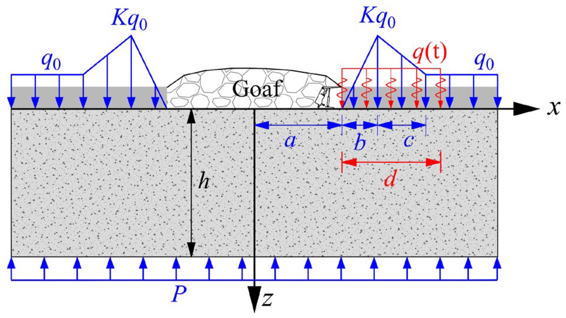
3.1. Mechanical Model of Mining Floor Under Combined Action of Dynamic and Static Loads

As illustrated in Figure 1, the loads acting on the mining floor primarily include the static load of abutment pressures and dynamic load generated by roof breakage during roof weighting. In previous studies, most scholars considered only the abutment pressure. However, the dynamic load accompanied by overlying roof strata fracturing and caving also affected the stress state of the floor. In this study, the stress components of the mining floor, considering the combined effects of dynamic and static loads, were calculated using the simplified mechanical model depicted in Figure 3.
In this figure, the dynamic load resulting from the breaking of the roof strata during the first weighting of the roof can be expressed as [35]:
q t = σ 0 sin 2 π ω t 0 t t 1 0 t > t 1
where σ 0 represents the dynamic load amplitude, ω denotes the dynamic load frequency, and t 1 is the dynamic load duration, and d indicates the lengths of dynamic load action(Figure 3). Based on the microseismic monitoring results obtained in underground coal mines, the dynamic load intensity usually ranges from 1.5 MPa~15 MPa, the frequency is usually dozens~100 Hz, and the duration is usually 0.01~0.1 s [36].
Utilizing the aforementioned mechanical calculation model, the vertical, horizontal, and shear stresses at any given point on the floor were obtained under the combined effects of the static and dynamic loads. Through the application of the stress superposition principle, a comprehensive analysis was conducted to assess the impact of dynamic loads on the stress distribution and failure mechanisms of the mining floor.

3.2. Theoretical Calculation Method

3.2.1. Stress Fields from Static Load

The static load stress field generated by the abutment pressure q x can be obtained from the stress solution at any point when the semi-plane body is subjected to a vertically distributed force on the boundary. The solution formula for the static load stress field of the floor can be obtained by taking a small length, dε as follows:
σ z = 2 π + z 3 q ε x ε 2 + z 2 2 d ε σ x = 2 π + z x ε 2 q ε x ε 2 + z 2 2 d ε τ x z = 2 π + z 2 x ε q ε x ε 2 + z 2 2 d ε

3.2.2. Stress Fields from Dynamic Load

According to the basic principle of elastodynamics, the equation of motion and physical equation of the elastic medium when physical force is not accounted for can be expressed as follows:
σ z z + τ x z x = ρ 2 w t 2 σ x x + τ x z z = ρ 2 u t 2
σ x = λ + 2 G u x + λ w z   σ z = λ + 2 G w z + λ u x τ x z = G u z + w x
where u and w are the displacements in the directions of x and z , respectively; ρ is the density of the floor strata; λ = μ E / 1 + μ 1 2 μ , G = E / 2 1 + μ , E is the modulus of elasticity; and μ is the Poisson’s ratio.
Combining (3) and (4) yields:
σ z z = ρ 2 w t 2 τ x z x τ x z z = ρ 2 u t 2 λ λ + 2 G σ z x 4 G λ + G λ + 2 G 2 u x 2 u z = τ x z G w x w z = σ z λ + 2 G λ λ + 2 G u x
The Laplace transform is applied at time t in Equation (5), and the Laplace transform and its inverse transform are defined as follows:
f ˜ x , z , s = L f x , z , t = 0 + f x , z , t e s t d t f x , z , t = L 1 f x , z , s = 1 2 π i β i β + i f ˜ x , z , s e s t d s
where s denotes the Laplace operator.
Before the action of a dynamic load, assuming the stress state at the surface of the mining floor is as follows:
w x , z , t t = 0 = 0 w x , z , t t = 0 = 0   u x , z , t t = 0 = 0     u x , z , t t = 0 = 0
Therefore, Equation (5) can be Laplace transformed into:
σ ˜ z x , z , s z = ρ s 2 w ˜ x , z , s τ ˜ x z x , z , s x τ ˜ x z x , z , s z = ρ s 2 u ˜ x , z , s μ 1 μ σ ˜ z x , z , s x E 1 μ 2 2 u ˜ x , z , s x 2 u ˜ x , z , s z = 2 1 + μ E τ ˜ x z x , z , s w ˜ x , z , s x w x , z , s z = 1 + μ 1 2 μ E 1 μ σ ˜ z x , z , s μ 1 μ u ˜ x , z , s x
To solve Equation (8), x is Fourier transformed, and its corresponding inverse transform is mathematically formulated as follows:
u ¯ , σ ¯ z , τ ¯ x z , w ¯ = u , σ z , τ x z , w e i ξ x d x u , σ z , τ x z , w = 1 2 π u ¯ , σ ¯ z , τ ¯ x z , w ¯ e i ξ x d ξ
where ξ is the Fourier transform parameter for x.
Then, Equation (8) is Fourier transformed and written in matrix form as:
z i σ ˜ ¯ z ξ , z , s τ ˜ ¯ x z ξ , z , s u ˜ ¯ ξ , z , s i w ˜ ¯ ξ , z , s = 0 ξ 0 ρ s 2 μ 1 μ ξ 0 ρ s 2 + E 1 μ 2 ξ 2 0 0 2 1 + μ E 0 ξ 1 + μ 1 2 μ E 1 μ 0 μ 1 μ ξ 0 i σ ˜ ¯ z ξ , z , s τ ˜ ¯ x z ξ , z , s u ˜ ¯ ξ , z , s i w ˜ ¯ ξ , z , s
Assuming the state component Ψ ˜ ¯ = i σ ˜ ¯ z τ ˜ ¯ x z u ˜ ¯ i w ˜ ¯ T , Equation (10) can be transformed into the following set of differential equations:
Ψ ˜ ¯ ξ , z , s z = A ρ , E , μ , ξ , s Ψ ˜ ¯ ξ , z , s
According to the calculation of matrix calculus, the solution of Equation (9) can be expressed as follows:
Ψ ˜ ¯ ξ , z , s = exp z A ρ , E , μ , s , ξ Ψ ˜ ¯ ξ , 0 , s
where Ψ ˜ ¯ ξ , 0 , s denotes the state vector after the Laplace transform and Fourier transform at z = 0.
According to the Hamilton–Cayley theorem, G ρ , E , μ , ξ , z , s = exp z A ρ , E , μ , ξ , s , Equation (12) is expressed in matrix form as:
i σ ˜ ¯ z ξ , z , s τ ˜ ¯ x z ξ , z , s u ˜ ¯ ξ , z , s i w ˜ ¯ ξ , z , s = G 11 G 12 G 13 G 14 G 21 G 22 G 23 G 24 G 31 G 32 G 33 G 34 G 41 G 42 G 43 G 44 i σ ˜ ¯ z ξ , 0 , s τ ˜ ¯ x z ξ , 0 , s u ˜ ¯ ξ , 0 , s i w ˜ ¯ ξ , 0 , s
where G 11 = G 44 = 1 + B ξ ch M z B ξ ch N z , G 12 = B N sh N z ξ 1 + B ξ M sh M z , G 13 = G 24 = ρ s 2 B 1 + B ξ ch N z ch M z , G 14 = ρ s 2 1 + B ξ 2 M sh M z ρ s 2 B 2 N sh N z , G 21 = G 43 = B M sh M z ξ 1 + B ξ N sh N z , G 22 = G 33 = 1 + B ξ ch N z B ξ ch M z , G 23 = ρ s 2 1 + B ξ 2 N sh N z ρ s 2 B 2 M sh M z , G 31 = G 42 = ξ ch M z ch N z ρ s 2 , G 32 = 1 ρ s 2 N sh N z ξ 2 M sh M z , G 34 = 1 + B ξ ξ M sh M z B N sh N z , G 41 = 1 ρ s 2 M sh M z ξ 2 N sh N z , B = E ξ ρ s 2 1 + μ , M = ρ s 2 1 2 μ μ + 1 E 1 μ + ξ 2 , and N = 2 ρ s 2 μ + 1 E + ξ 2 .
The relationship between any depth of the floor and the surface state vector is as follows:
Ψ ˜ ¯ ξ , z , s = G ρ , E , μ , ξ , h , s Ψ ˜ ¯ ξ , 0 , s
The boundary conditions at the top of the floor ( z = 0 ) and infinite depth ( z = ) are expressed as follows:
σ z x , z , t z = 0 = q t τ x z x , z , t z = 0 = 0 u x , z , t z = = w x , z , t z = = 0
After the Laplace transform of t and the Fourier transformation of x are performed in Equation (15), the dynamic response of the mining floor can be obtained by substituting Equation (14). The vertical, horizontal, and shear stresses of the floor were calculated using MATLAB (R2017a) programming. Through vector superposition analysis, the propagation mechanisms of the dynamic loads and their effects on stress distribution within the floor were determined by analyzing variations in these stress components across the dynamic load cycles. Building on these results, the stress response characteristics of the floor when subjected to the combined effects of static and dynamic loads were systematically investigated.

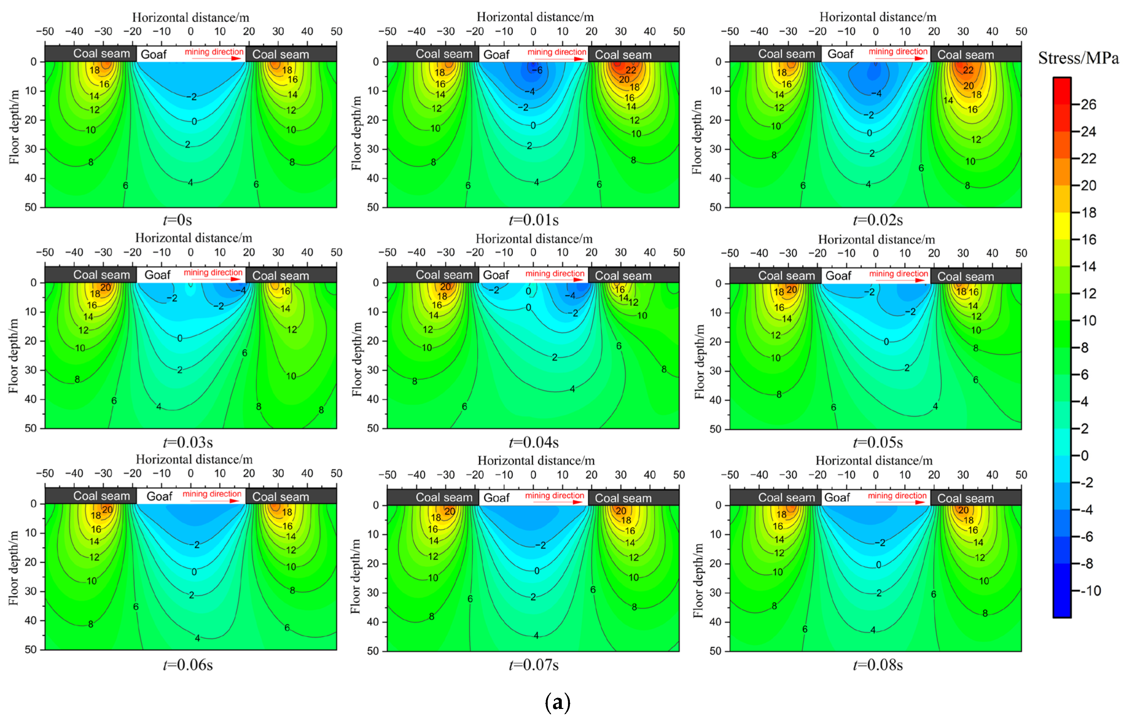
3.3. Dynamic Response Characteristics of Mining Floor

According to the actual mining data and in situ measurement results of the working face, the parameters of the floor stratum are averaged, the modulus of elasticity E = 16.6 GPa, Poisson’s ratio μ = 0.26 , and density ρ = 2650 kg / m 3 . The roof first weighting step is 36 m, so a = 18 m. The stress increasing zone length b = 10 m, stress decreasing zone length c = 20 m, γH = 10 MPa, stress concentration coefficient K = 2.5, and the water pressure P = 3 MPa. The dynamic load q t parameters acting on the floor are σ 0 = 8 MPa , ω = 20 H z , t 1 = 0.05 s . The dynamic load action calculation time is 0.08 s, action range d = 20 m, and the dynamic load stress time–history curve is shown in Figure 4.
The stress distribution within the floor strata was computationally analyzed using MATLAB, as illustrated in Figure 5. Before the roof first weighting, the mining floor experienced exclusively static loading conditions. The synergistic effects of abutment pressure and hydrostatic pressure induced substantially elevated vertical stresses in proximity to the coal seam, forming distinct stress concentration zones beneath the rib pillars flanking the longwall face. Concurrently, strata beneath the goaf exhibited marked stress relaxation. The maximum vertical stress in the floor was 21.8 MPa below the coal body, approximately 10 m away from the working face, with the maximum influence depth of the abutment pressure being approximately 24.5 m. The vertical stress field was significantly affected when the floor rock masses were subjected to the dynamic load caused by roof weighting. The extent and area of stress concentration in the floor increased with the effects of dynamic loading below the coal body of the unmined area. Quantitative analysis revealed peak vertical stress magnitude reaching 25.5 MPa, and the maximum influence depth was more than 34.2 m (Figure 5a). Before the dynamic loading, the horizontal stress distribution of the floor was similar to the vertical stress, and the maximum value was 18.9 MPa below the coal body. During the dynamic loading, the maximum value of the vertical stress was 21.2 MPa (Figure 5b). Horizontal stress is less affected than vertical stress during dynamic loading because the dynamic load is applied as vertical stress during the calculation. Similar to the vertical stress, the extent and area of the shear stress concentration increased significantly. The maximum shear stress below the coal body where the dynamic loads are applied increased from 5.7 MPa to 6.6 MPa (Figure 5c).

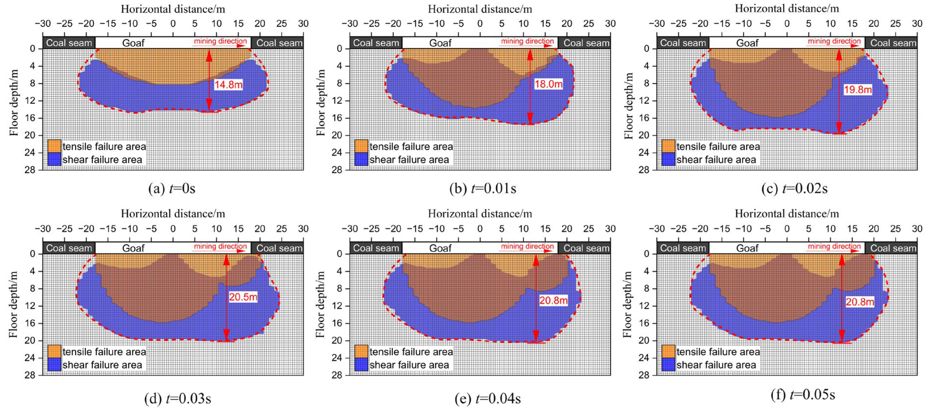
3.4. Floor Failure Depth and Characteristics

FDMF serves as a critical parameter for risk assessment of FWI hazards. As determined by the study above, dynamic loading induces significant modifications to the floor’s stress distribution, which will unavoidably have an immediate effect on the extent of floor failure. For quantitative evaluation of this critical parameter, the Mohr–Coulomb yield criterion has been implemented to reflect the floor rock failure under tensile and shear stresses in the following model:
f t = σ 3 σ t f c = σ 1 σ 3 1 + sin φ 1 sin φ + 2 c cos φ 1 sin φ
where σ1 and σ3 denote the maximum and minimum principal stress, respectively (MPa); σt is the tensile strength (MPa); φ is the internal friction angle of the floor stratum (°); c is the cohesion force (MPa). Tensile failure occurs in the rock mass when f t 0 , while shear failure occurs when f c 0 [37].
The average values of the floor stratum parameters were taken as φ = 25.5°, c = 3.2 MPa, σ t = 2.6 MPa. The cumulative failure zone of the floor during dynamic loading is obtained by substituting the relevant parameters.
As illustrated in Figure 6, prior to the first roof weighting, tensile failure occurs in the floor rock masses within 8.2 m below the goaf due to the combined effects of abutment pressure and water pressure. With increasing depth, the failure mode transitions to shear failure, reaching a maximum FDMF of approximately 14.8 m (Figure 6a). Following the effect of dynamic loads induced by roof weighting, the tensile and shear failure zone in the floor expands progressively as dynamic stress propagates through the floor. The tension failure zone increases to 16.1 m (96%), and the maximum FDMF increases to 20.8 m after dynamic loading (Figure 6b–f), representing an increase of 6.0 m (40.5%) compared to the static loading scenario.

4. Numerical Simulation and Field Measurement

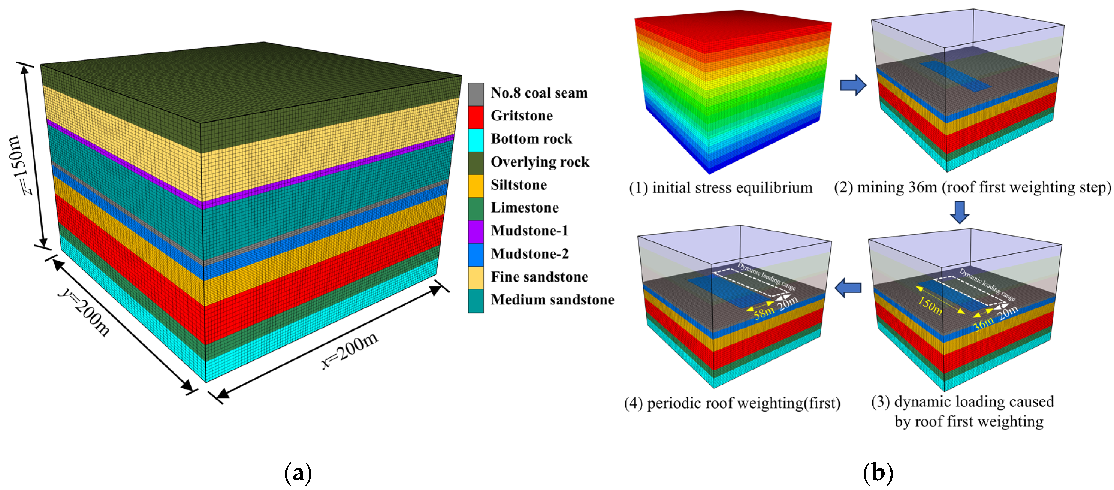
4.1. Numerical Model and Simulation Results

Taking into account the geological conditions in the study area, along with the actual dimensions of the working face, a 3D numerical model for mining the 8402 working face was established using the FLAC3D(v6.0) software. The model dimensions (length × width × height) were 200 m × 200 m × 150 m, and the number of particles in the model was approximately 161,000 (Figure 7). An evenly distributed vertical load (9.5 MPa) was applied on the upper boundary to represent the overburden stress from the overlying rock strata. All stratigraphic units in the model were assigned the Mohr–Coulomb failure criterion, with mechanical parameters derived from laboratory test data (Table 2).
Figure 8 delineates the plastic zone distribution of the mining floor under static and dynamic loading conditions at the central monitoring section (y = 100 m) of the working face. As demonstrated in Figure 8a, prior to dynamic loading (when advancing 36 m to reach the first roof weighting stage), the floor failure pattern exhibited an inverted saddle geometry under static abutment pressure, displaying symmetrical distribution about the working face centerline. The initial maximum FDMF of 15.7 m occurred bilaterally along the working face margins, dominated by shear failure mechanisms. After dynamic loading (Figure 8b), The floor plastic zones further increased compared with the results before dynamic loading. The failure area underwent significant expansion with a 32.5% increase in maximum FDMF to 20.8 m.
When the working face was excavated 58 m (the position of periodic roof weighting), FDMF was still 20.8 m (Figure 8c). Therefore, it can be deduced that the FDMF did not significantly increase as the working face advanced. Meanwhile, the maximum FDMF reached 22.9 m after dynamic loading owing to roof periodic weighting (Figure 8d). These findings demonstrate that FDMF was significantly influenced by dynamic loads.

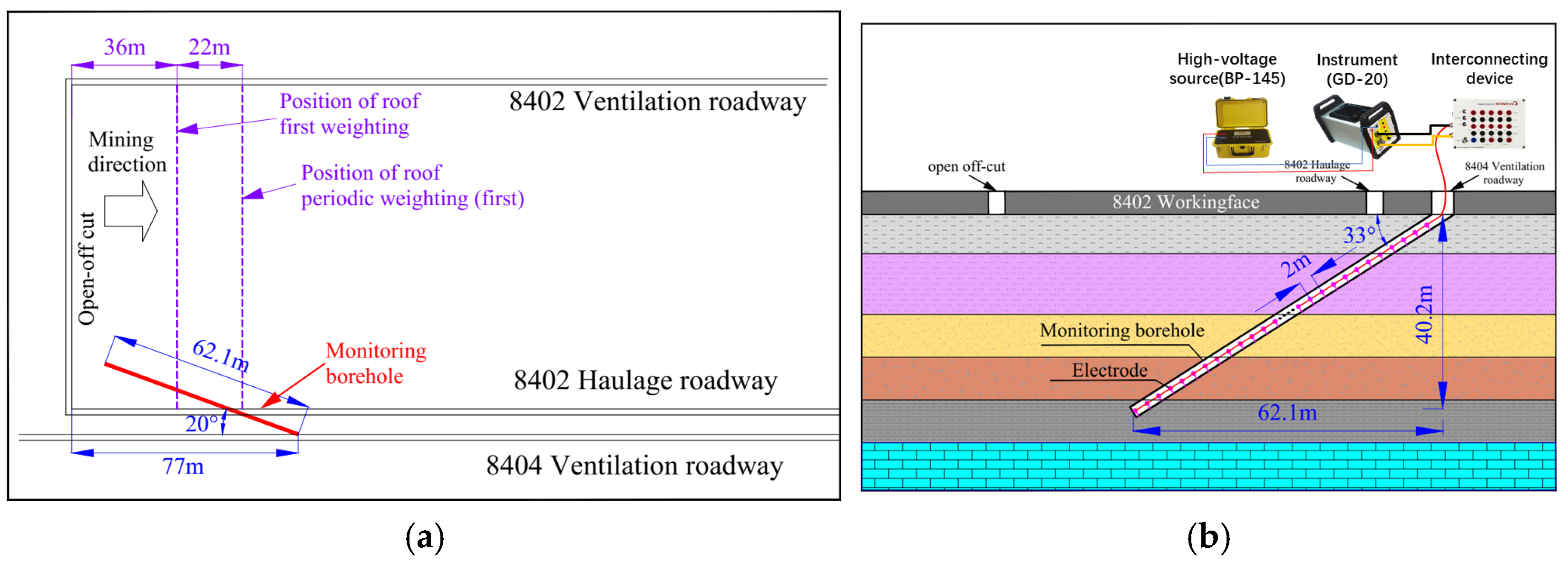
4.2. Field Measurement

To accurately measure the FDMF of the 8402 working face at various mining stages, borehole resistivity measurements were carried out in the ventilation roadway of the adjacent 8404 working face. The construction and layout of the borehole are illustrated in Figure 9. For the field measurement, a 91 mm diameter borehole was drilled into the floor at a distance of 77 m from the open-off cut. The tests were conducted using the GD-20 electrical measurement system. It includes one operating instrument, a high-voltage source, and an interconnecting device. The electrodes were placed in the borehole and coupled with the surrounding rock by injecting cement slurry.
In order to obtain data from different mining stages, field measurements were taken in 15 m intervals along the working face advance. The resistivity of rocks at different depths within the floor was continuously monitored from the unmined state of the working face until it had advanced 60 m. Due to space constraints, only four sets of data were selected for analysis. The resistivity distribution of the floor at various mining distances is presented in Figure 10.
As shown in Figure 10a, background resistivity measurements were obtained before the excavation of the working face, with the resistivity of the floor rock masses ranging from 20 to 450 Ω⋅m.
When the working face advanced to 30 m, a notable increase in the resistivity was observed in the floor rock masses of the mined area (Figure 10b). The resistivity at depths of 0 to 12.2 m was 3 to 5 times higher than the background values. As mining progressed, the maximum resistivity in this zone reached 1582 Ω⋅m. The expansion of the high-resistivity region indicated significant disturbance and damage to the floor strata caused by mining activities. At this stage, the coal mining face was still 6 m away from the position of the first roof weight, and the maximum FDMF was approximately 12.2 m.
Figure 10c shows an abnormally high resistivity area developed within a depth range of 0~21.4 m when the working face advanced to 45 m. This area exhibited an overall resistivity of 1700 Ω⋅m, which was more than five times the background resistivity. This indicates that, within this depth range, the cracks generated in the floor rock masses were further extended, eventually forming a floor failure zone. At this stage, the working face had advanced 9 m following the roof first weighting (with a first weighting step distance of 36 m), and the floor failure zone extended to a depth of 21.4 m below the floor. Compared to the results before the roof first weighting, the FDMF increased by 9.2 m, representing a 75.4% rise. These results demonstrate that the FDMF was significantly amplified under the dynamic loads induced by roof weighting.
The resistivity distribution of the floor strata when the working face advanced to 60 m is depicted in Figure 10d. At this stage, the working face had advanced 2 m after the roof periodic weighting (first), and the maximum FDMF further increased to 23.4 m under dynamic loads caused by roof weighting. Therefore, the field monitoring results show that floor failure can be influenced by the roof periodic weighting too. This finding validates the rationalization of the proposed model.

5. Discussion and Conclusions

(1)
Considering the coal seam floor under the combined effects of the dynamic loads induced by roof breakage and the static loads induced by abutment pressure, a new mechanical method that comprehensively considers the effect of dynamic disturbance on the floor is established to theoretically calculate the floor stress field and FDMF. With a comprehensive consideration of the mining floor under multi-stress conditions in the proposed model, the obtained results are more realistic than those obtained using traditional methods.
(2)
The theoretical analysis results reveal that the stress field of the floor demonstrates distinct dynamic characteristics due to the dynamic loads induced by roof weighting. These findings indicate that dynamic loads significantly influence vertical and shear stresses, while their effect on horizontal stress is minimal. Moreover, the dynamic load complicates the variation characteristics of the floor stress fields more than static load action alone. The dynamic loading expands the stress concentration zone and intensifies the degree of stress concentration of the mining floor, inevitably leading to a further increase in the maximum FDMF.
(3)
To verify the accuracy of the proposed model, numerical simulations and field measurements were carried out. A comparative analysis of the results obtained from the above three methods is summarized in Table 3.
As summarized in Table 3, the floor failure derived from theoretical calculations, numerical simulation, and the field measurements were 14.5 m, 15.7 m, and 12.2 m respectively, when the mining floor was under static loads such as abutment pressures and water pressure before roof first weighting. Owing to the dynamic loads caused by roof first weighting, the FDMF increased to 20.8 m, 20.8 m, and 21.4 m respectively. The results demonstrate that the FDMF is significantly greater under dynamic loading. Furthermore, the close agreement among the three sets of results validates the reliability of the theoretical model. Additionally, numerical simulations and field measurements were employed to investigate the maximum FDMF after roof periodic weighting (first). Both methods confirmed a substantial increase in FDMF under dynamic loads caused by roof weighting. These findings highlight that the proposed model serves as a simple yet effective tool for analyzing floor stress fields and failure depths under combined static and dynamic loading conditions.

Author Contributions

Conceptualization, writing—review and editing, Q.H. and B.X.; investigation, writing—original draft preparation, X.W.; methodology, data curation, J.F.; validation, software, J.P. All authors have read and agreed to the published version of the manuscript.

Funding

This research was funded by the Natural Science Foundation of Anhui Province (2008085QE221), the China Postdoctoral Science Foundation funded project (2022M712934), the Key Research and Development Plan of Anhui Province (Grant no. 2022m07020001), the Postdoctoral Foundation of Anhui Province (2021B550, 2021B551), and the Open Research Program of State Key Laboratory of Safety and Health for Metal Mines (2023-JSKSSYS-07).

Data Availability Statement

The original contributions presented in this study are included in the article. Further inquiries can be directed to the corresponding author.

Acknowledgments

The authors express their gratitude to the anonymous reviewers for their detailed comments and suggestions, which have greatly enhanced the quality of this paper.

Conflicts of Interest

Authors Qisong Huang, Junjun Feng and Jun Peng were employed by the company Sinosteel Maanshan General Institute of Mining Research Co., Ltd. The remaining authors declare that the research was conducted in the absence of any commercial or financial relationships that could be construed as a potential conflict of interest.

References

  1. Li, J.; Xu, Q.; Hu, Y.; Chen, X. Evaluation of Control Effect of Confined Water Hazard in Taiyuan Formation Coal Seam Mining in Huanghebei Coalfield. Water 2023, 15, 1973. [Google Scholar] [CrossRef]
  2. Hu, W.; Zhao, C. Evolution of Water Hazard Control Technology in China’s Coal Mines. Mine Water Environ. 2021, 40, 334–344. [Google Scholar] [CrossRef]
  3. Li, C.Y.; Zuo, J.P.; Wei, C.C.; Xu, X.; Zhou, Z.Q.; Li, Y.; Zhang, Y. Fracture Development at Laminated Floor Layers Under Longwall Face in Deep Coal Mining. Nat. Resour. Res. 2020, 29, 3857–3871. [Google Scholar] [CrossRef]
  4. Li, C.Y.; Zuo, J.P.; Huang, X.H.; Wu, G.S.; Li, Y.B.; Xing, S.K. Water Inrush Modes Through a Thick Aquifuge Floor in a Deep Coal Mine and Appropriate Control Technology: A Case Study from Hebei, China. Mine Water Environ. 2022, 41, 954–969. [Google Scholar] [CrossRef]
  5. Li, H.L.; Bai, H.B. Simulation Research on the Mechanism of Water Inrush from Fractured Floor under the Dynamic Load Induced by Roof Caving: Taking the Xinji Second Coal Mine as an Example. Arab. J. Geosci. 2019, 12, 466. [Google Scholar] [CrossRef]
  6. Xu, J.L. Green Mining of Coal Mine; China University of Mining and Technology Press: Xuzhou, China, 2011. [Google Scholar]
  7. Li, W.P.; Li, X.Q.; Sun, R.H. Preliminary Study on Dynamic Water Inrush of Coal Mining Under Super-Thick Hard Rock. J. Eng. Geol. 2008, 16, 446–450. [Google Scholar]
  8. Li, C.Y. Fracture Mechanism and Its Model of Floor Rock Mass under Stong Disturbance in Deep Coal Mining. Ph.D. Thesis, China University of Mining & Technology(Beijing), Beijing, China, 2018. [Google Scholar]
  9. Huang, D. Study on Deformation and Failure Mechanism of Deep Coal Seam Floor in Xingdong Mining Area. Ph.D. Thesis, Chang’an University, Xi’an, China, 2019. [Google Scholar]
  10. Guan, Y.Q. Investigation on the Mechanism of Water Inrush in 15423N Working Face of Jiulong Coal Mine. Coal Sci. Technol. 2012, 40, 105–108. [Google Scholar]
  11. Shang, Y.P.; Li, G.C.; Li, H.G. Fast Plugging Water Inrush of Ordovician Limestone in No. 81004 Working Face. In Proceedings of the Excellent Academic Proceedings in 2004 of Shandong Institute of Coal; Jinan Press: Jinan, China, 2004; pp. 185–190. [Google Scholar]
  12. Jin, D.W. Analysis of Water Inrush in the 12 and 13 Mining Areas of JiuLiShan Mine. Coal 1998, 7, 59–61. [Google Scholar]
  13. Kong, P.; Jiang, L.S.; Jiang, J.Q.; Wu, Y.N.; Chen, L.J.; Ning, J.G. Numerical Analysis of Roadway Rock-Burst Hazard under Superposed Dynamic and Static Loads. Energies 2019, 12, 3761. [Google Scholar] [CrossRef]
  14. Wang, X.H.; Zhu, S.Y.; Cao, S.W.; Zhang, M. Study of Floor Failure Characteristics and Water-Inrush Risk in a Working Face of Lower Coal Seam. Arab. J. Geosci. 2022, 15, 739. [Google Scholar] [CrossRef]
  15. Shi, X.F.; Jiang, F.X.; Zhu, S.T.; Yang, G.Y. Mechanism of Integrated Dynamic Disaster of Rockburst and Water Inrush: A New Type of Integrated Dynamic Disaster in China. Geotech. Geol. Eng. 2017, 35, 1261–1270. [Google Scholar] [CrossRef]
  16. Zhang, H.L.; Cao, J.J.; Tu, M. Floor Stress Evolution Laws and Its Effect on Stability of Floor Roadway. Int. J. Min. Sci. Technol. 2013, 23, 631–636. [Google Scholar] [CrossRef]
  17. Feng, Q.; Jiang, B.S. Analytical Solution for Stress and Deformation of the Mining Floor Based on Integral Transform. Int. J. Min. Sci. Technol. 2015, 25, 581–586. [Google Scholar] [CrossRef]
  18. Huang, Q.S.; Cheng, J.L. Analytical Model of Stress Field and Failure Depth in Multilayered Rock Masses of Mining Floor Based on the Transfer Matrix Method. Geotech. Geol. Eng. 2017, 35, 2781–2788. [Google Scholar] [CrossRef]
  19. Li, J.Z.; Guo, P.G.; Yuan, A.Y.; Zhu, C.Q.; Zhang, T.; Chen, D.H. Failure Characteristics Induced by Unloading Disturbance and Corresponding Mechanical Mechanism of the Coal-Seam Floor in Deep Mining. Arab. J. Geosci. 2021, 14, 1170. [Google Scholar] [CrossRef]
  20. Sun, J.; Hu, Y.; Zhao, G.M. Relationship between Water Inrush from Coal Seam Floors and Main Roof Weighting. Int. J. Min. Sci. Technol. 2017, 27, 873–881. [Google Scholar] [CrossRef]
  21. Zhao, C.B.; Hebblewhite, B.K.; Galvin, J.M. Analytical Solutions for Mining Induced Horizontal Stress in Floors of Coal Mining Panels. Comput. Methods Appl. Mech. Eng. 2000, 184, 125–142. [Google Scholar] [CrossRef]
  22. Wang, P.; Jiang, L.S.; Ma, C.Q.; Yuan, A.Y. Evolution Laws of Floor Stress and Stability of Floor Roadway Affected by Overhead Mining. Earth Sci. Res. J. 2020, 24, 45–54. [Google Scholar] [CrossRef]
  23. Meng, X.X.; Liu, W.T.; Zhao, J.Y.; Ding, X.Y. In Situ Investigation and Numerical Simulation of the Failure Depth of an Inclined Coal Seam Floor: A Case Study. Mine Water Environ. 2019, 38, 686–694. [Google Scholar] [CrossRef]
  24. Lu, Y.L.; Wang, L.G. Numerical Simulation of Mining-Induced Fracture Evolution and Water Flow in Coal Seam Floor above a Confined Aquifer. Comput. Geotech. 2015, 67, 157–171. [Google Scholar] [CrossRef]
  25. Li, A.; Ding, X.S.; Yu, Z.Z.; Wang, M.; Mu, Q.; Dai, Z.X.; Li, H.Y.; Zhang, B.; Han, T.R. Prediction Model of Fracture Depth and Water Inrush Risk Zoning in Deep Mining Coal Seam Floor. Environ. Earth Sci. 2022, 81, 315. [Google Scholar] [CrossRef]
  26. Li, Z.; Yang, Z.; Wang, S.; Ren, L.; Fang, J. The Effects of Coal Floor Brittleness on the Risk of Water Inrushes from Underlying Aquifers: A Numerical Study. Sustainability 2024, 16, 1489. [Google Scholar] [CrossRef]
  27. Zhang, B.L.; Meng, Z.B. Experimental Study on Floor Failure of Coal Mining above Confined Water. Arab. J. Geosci. 2019, 12, 114. [Google Scholar] [CrossRef]
  28. Yin, H.Y.; Lefticariu, L.; Wei, J.C.; Guo, J.B.; Li, Z.J.; Guan, Y.Z. In Situ Dynamic Monitoring of Stress Revolution with Time and Space under Coal Seam Floor during Longwall Mining. Environ. Earth Sci. 2016, 75, 1249. [Google Scholar] [CrossRef]
  29. Zhou, W.L.; Zhang, P.S.; Wu, R.X.; Hu, X.Y. Dynamic Monitoring the Deformation and Failure of Extra-Thick Coal Seam Floor in Deep Mining. J. Appl. Geophys. 2019, 163, 132–138. [Google Scholar] [CrossRef]
  30. Duan, H.F.; Zhao, L.J.; Chen, Y. Effect of Floor Failure in Fully Mechanized Caving of Extra-Thick Coal Seam in Datong Mining Area. Arab. J. Geosci. 2021, 14, 1008. [Google Scholar] [CrossRef]
  31. Wang, B.; Zhang, J.; Lin, H.; Liu, H.; Gao, S.; He, Y. The Catastrophic Failure Mechanisms and the Prevention of Dynamic Pressure-Related Hazards during Mining under an Interval Goaf through an Isolated Coal Pillar in Shallow and Closely Spaced Coal Seams. Appl. Sci. 2024, 14, 10554. [Google Scholar] [CrossRef]
  32. Li, S.C.; Wu, J.; Xu, Z.H.; Yang, W.M. Mechanics Criterion of Water Inrush from the Coal Floor under Influence of Fault and Its Engineering Application. Int. J. Geomech. 2019, 19, 04019022. [Google Scholar] [CrossRef]
  33. Xu, D.J.; Peng, S.P.; Xiang, S.Y.; Liang, M.X.; Liu, W.M. The Effects of Caving of a Coal Mine’s Immediate Roof on Floor Strata Failure and Water Inrush. Mine Water Environ. 2016, 35, 337–349. [Google Scholar] [CrossRef]
  34. Cao, M.; Yin, S.; Li, S.; Wang, X. Mechanisms of Thick-Hard Roof and Thin Aquifer Zone Floor Destruction and the Evolution Law of Water Inrush. Water 2024, 16, 2304. [Google Scholar] [CrossRef]
  35. Lv, J.K.; Wan, Z.J.; Yang, Y.J.; Wang, J.H.; Zhang, Y.; Liu, S.F. Failure Characteristics and Stability Control Technology of Dynamic Pressure Roadway Affected by the Mining Activity: A Case Study. Eng. Fail. Anal. 2022, 131, 105857. [Google Scholar] [CrossRef]
  36. Cai, W.; Dou, L.M.; Si, G.Y.; Hu, Y.W. Fault-Induced Coal Burst Mechanism under Mining-Induced Static and Dynamic Stresses. Engineering 2021, 7, 14. [Google Scholar] [CrossRef]
  37. Yin, H.Y.; Sang, S.Z.; Xie, D.L.; Zhao, H.; Li, S.J.; Li, H.S.; Zhuang, X.H. A Numerical Simulation Technique to Study Fault Activation Characteristics during Mining between Fault Bundles. Environ. Earth Sci. 2019, 78, 148. [Google Scholar] [CrossRef]
Figure 1. Schematic of loading on mining floor during roof weighting periods.
Water 17 00699 g001
Figure 2. Location, plane layout, and geological column of the study area.
Water 17 00699 g002
Figure 3. Mechanical model for calculating the floor stress.
Water 17 00699 g003
Figure 4. Time–history curve of the dynamic load.
Water 17 00699 g004
Figure 5. Stress distribution of the floor at different loading times (unit: MPa). (a) Vertical stress. (b) Horizontal stress. (c) Shear stress.
Water 17 00699 g005aWater 17 00699 g005b
Figure 6. Cumulative FDMF during dynamic loading.
Water 17 00699 g006
Figure 7. Numerical model and simulation steps. (a) numerical model; (b) simulation steps.
Water 17 00699 g007
Figure 8. Plastic zone distribution in the floor at different mining stages. (a) Advance 36 m, before roof first weighting; (b) after roof first weighting; (c) advance 58 m, before roof periodic weighting (first); (d) after roof periodic weighting (first).
Water 17 00699 g008
Figure 9. The borehole layout and field test system. (a) Layout diagram of the monitoring borehole; (b) geological profile of the borehole.
Water 17 00699 g009
Figure 10. Resistivity distribution of floor at different mining distances. (a) Background resistivity data; (b) advance 30 m, before roof first weighting; (c) advance 45 m, after roof first weighting; (d) advance 60 m, after roof periodic weighting (first).
Water 17 00699 g010
Table 1. Typical cases of FWI accidents in Chinese coal mines.
Sequence NumberCoal Mine NameDescription of Water InrushReference
1Shigu coal mineThree FWI accidents occurred when working face advanced to the position of roof first or periodic weighting in 9304 working face.[6]
2Zhaogezhuang coal mine A delayed floor fault water inrush accident occur at in the third mining level. And accompanied by rockburst accident.[7]
3Zhaogu No.1 coal mineFWI accidents occurred at 12,041 working face in Xierpan mining area during the period of roof first weighting, with the maximum water flow approximately 486 m3/h. And new water inrush channels formed during the periods of roof periodic weighting[8]
4Xingdong coal mine2011.04~2015.05, FWI occurred at 2125, 2126, 2222 and 2228 working face at mining level −980 m. Those accidents correlate between FWI and periodic weighting.[9]
5Jiulong coal mineThree water inrush accident happened in 15,423 N working face. Due to the periodic roof weighting, second FWI incident occurred accompanied by the floor heave.[10]
6Caozhuang coal mineIn March 2004, FWI occurred after a strong roof weighting when 81,004 working face advanced to 360 m. And the maximum amount of water inrush is approximately 403 m3/h.[11]
7Jiulishan coal mineFWI accidents occurred at the position of first roof weighting when the working face advanced about 20 m in 12,031, 12,021, 12,011 working faces of mining area 12.[12]
Table 2. Mechanical parameters of the model.
LithologyThickness/(m)Elastic Modulus/
(GPa)
Poisson RatioFriction Angle/
(°)
Cohesion/(MPa)Tensile Strength/
(MPa)
Density/
(kg·m−3)
Overlying rock14.930.790.27352.62.82500
Fine sandstone25.529.180.26343.12.42630
Mudstone-14.223.500.28332.21.82570
Medium sandstone28.618.500.25344.52.82700
No.8 coal seam3.513.080.23231.20.81620
Mudstone-28.516.970.28242.21.42540
Siltstone15.418.010.25262.81.72650
Gritstone24.621.510.25293.12.32720
Limestone10.835.740.23374.52.62450
Bottom rock1444.210.20395.62.82760
Table 3. Comparison of theoretical calculations, numerical simulation, and field measurements.
Before Roof First WeightingAfter Roof First WeightingAfter Roof Periodic Weighting (First)
Theoretical calculation14.8 m20.8 m
Numerical simulation15.7 m20.8 m22.9 m
Field measurement12.2 m21.4 m23.4 m
Disclaimer/Publisher’s Note: The statements, opinions and data contained in all publications are solely those of the individual author(s) and contributor(s) and not of MDPI and/or the editor(s). MDPI and/or the editor(s) disclaim responsibility for any injury to people or property resulting from any ideas, methods, instructions or products referred to in the content.

