Article

Study on Large-Scale Geomechanical Experiments on Tunnel External Water Pressure

1
Research Institute of Geotechnical Engineering, Hohai University, Nanjing 210098, China
2
Key Laboratory of Ministry of Education for Geomechanics and Embankment Engineering, Hohai University, Nanjing 210098, China
3
Laboratory of Multiscale and Multiphysics Mechanics, University of Lille, 59000 Lille, France
*
Author to whom correspondence should be addressed.
Water 2025, 17(7), 913; https://doi.org/10.3390/w17070913
Submission received: 3 March 2025 / Revised: 15 March 2025 / Accepted: 19 March 2025 / Published: 21 March 2025
(This article belongs to the Topic Carbon-Energy-Water Nexus in Global Energy Transition)

Abstract

:
High external water pressure poses significant challenges to the construction of long-distance water diversion tunnels under complex geological conditions. This study developed a large-scale geomechanics model to explore the effects of tunnel depth, water head, and drained conditions on external water pressure, focusing on the Songlin Tunnel in the Central Yunnan Water Diversion Project. The results show that external water pressure is most affected by water head and tunnel depth, particularly under undrained conditions. At water heads over 160 m, the external water pressure significantly decreases with an increasing tunnel depth. The suggested coefficients are 0.65–0.80 for shallowly buried tunnels with high water heads and 0.50–0.65 for deeply buried tunnels with low water heads. For drained conditions, the recommended reduction coefficients are 0.30–0.55 for the arch vault and spandrels. For the haunch, arch springing, and arch bottom, the suggested coefficients are 0.50 to 0.60 under the low water head and 0.40 to 0.60 under the high water head. These findings offer practical guidance for the design and safety of hydraulic tunnels under high external water pressure.

1. Introduction

High external water pressure poses a significant challenge in the design and operation of long-distance water diversion tunnels. These projects are typically characterized by long tunnel routes and complex geological conditions [1,2]. Under complex geological conditions, groundwater may accumulate and impose high external water pressure on tunnel linings. In severe cases, this pressure can exceed the design limits of the lining, leading to structural failures such as cracking, water leakage, and even catastrophic tunnel collapse [3]. Additionally, prolonged water ingress can cause deterioration of the tunnel lining, further compromising structural integrity [4,5].
External water pressure is the hydrostatic force imposed by surrounding groundwater on the exterior surface of the tunnel lining. The magnitude of this pressure depends on factors such as geological conditions, groundwater table height, and tunnel structural characteristics. To thoroughly investigate and address the external water pressure in tunnels, researchers have employed theoretical analyses, numerical simulations, and geomechanical model experiments.
Theoretical studies typically assume that surrounding rock is homogeneous, isotropic, and continuous, with a steady-state laminar flow that adheres to Darcy’s law. Under this assumption, the external water pressure on the lining is derived through seepage theory. For instance, Bobet [6,7] and Nam et al. [8] systematically derived tunnel lining stresses under small deformations using the relative stiffness method. Duan et al. [9] introduced the equivalent hydraulic radius method into the seepage theory of fractured media, deriving the distribution laws of seepage pressure at various distances from the tunnel wall through theoretical analysis. A theoretical model applied to a mountainous region with elevated water levels was used to examine the relationship between external water pressure and tunnel discharge [10]. It was found that an increasing tunnel discharge reduces the external water pressure, likely due to lower groundwater levels [11,12]. Shen et al. [13] conducted numerical simulations examining the external water pressure in seepage anisotropy under heterogeneous geological conditions, highlighting that the external water pressure significantly increases with the anisotropy of permeability and emphasizing the effectiveness of grouting rings in reducing water pressure.
In practical engineering with complex geological structures and diverse rock types, numerical methods are preferred for their efficiency and precision. These methods include the Equivalent Continuum Model (ECM), Discrete Fracture Network (DFN), and the dual medium approach. The ECM conceptualizes fractured aquifers as continuous media, as detailed by Schwartz et al. [14] and Xie et al. [15]. Conversely, the DFN method treats fractured aquifers as discrete media [16,17,18,19]. It uses an equivalent continuous medium-fracture network coupled seepage model to simulate the seepage field and tunnel fields, validating the drainage system’s effectiveness. Shin et al. [20] used finite element calculations to analyze the impact of the external water pressure on lining stresses, proposing design curves for the deterioration of drained conditions. Arjnoi et al. [21] performed finite element analyses to study the Bangkok subway tunnel’s external water pressure, seepage, and lining stresses under different drained conditions. Although theoretical calculations and numerical simulations are essential, they often cannot fully capture the complex interactions between geological conditions and tunnel structures.
Geomechanical model experiments conducted in controlled laboratory settings can replicate the complex stress conditions encountered in the field. By manipulating parameters such as the water pressure, lining materials, and tunnel geometry, researchers can better understand the failure mechanisms and determine critical pressure thresholds for practical applications. For example, Li et al. [22] used a 3D-printed model to experimentally investigate tunnel invert deformation, comparing traditional and optimized drainage systems in China. Fang et al. [23] developed an apparatus by evacuating air from the tunnel’s interior space to examine the relationship between lining bending moments and external water pressure under extreme conditions. Fan et al. [24] and Li et al. [25] designed seepage model experimental systems to analyze the failure characteristics of lining structures under varying rainfall recharges and tunnel drainage. Wang et al. [26] conducted model experiments to study the influence of grouting zones on tunnel water pressure and seepage fields. Additionally, Qian et al. [27] performed laboratory model experiments to assess the impacts of drainage system blockages on lining stresses in karst tunnels, concluding that increased blockage significantly elevates external water pressures, thereby compromising the lining’s structural safety. Numerous researchers have also examined the failure mechanisms of tunnel linings subjected to high external water pressures [28,29,30,31].
This study developed a geomechanical model experimental system to explore the evolution of external water pressure under varying conditions. Different tunnel depths, water heads, and drained conditions were simulated based on the geological conditions of the Songlin Tunnel in the Central Yunnan Water Diversion Project. The experiments provided an in-depth analysis of the variations in external water pressure under these complex geological conditions, revealing the distribution of water pressure on the tunnel lining. These findings provide valuable insights and practical guidance for designing, constructing, and ensuring the operational safety of water diversion tunnels.

2. Background

The Songlin Tunnel is part of the Kunming section of the Central Yunnan Water Diversion Project, which spans a total length of 116.758 km. This section includes six tunnels with a combined length of 108.291 km, accounting for 92.75% of the total route. Approximately 41.43% of the tunnels pass through karstic rock, with most segments located below the groundwater level. Around 31.25 km of the tunnels in this section are subject to high external water pressures of at least 0.5 MPa.
Figure 1 shows the water gushing from the large pipe shed in the Songlin Tunnel. The measured external water pressure reached 1.5 MPa, with a peak of up to 2.5 MPa. Because the original design could only withstand an external water head of 50 m, geomechanical model experiments were required to determine the external water pressure on the tunnel lining and modify the lining structure design to meet the project’s requirements.

3. Geomechanical Model

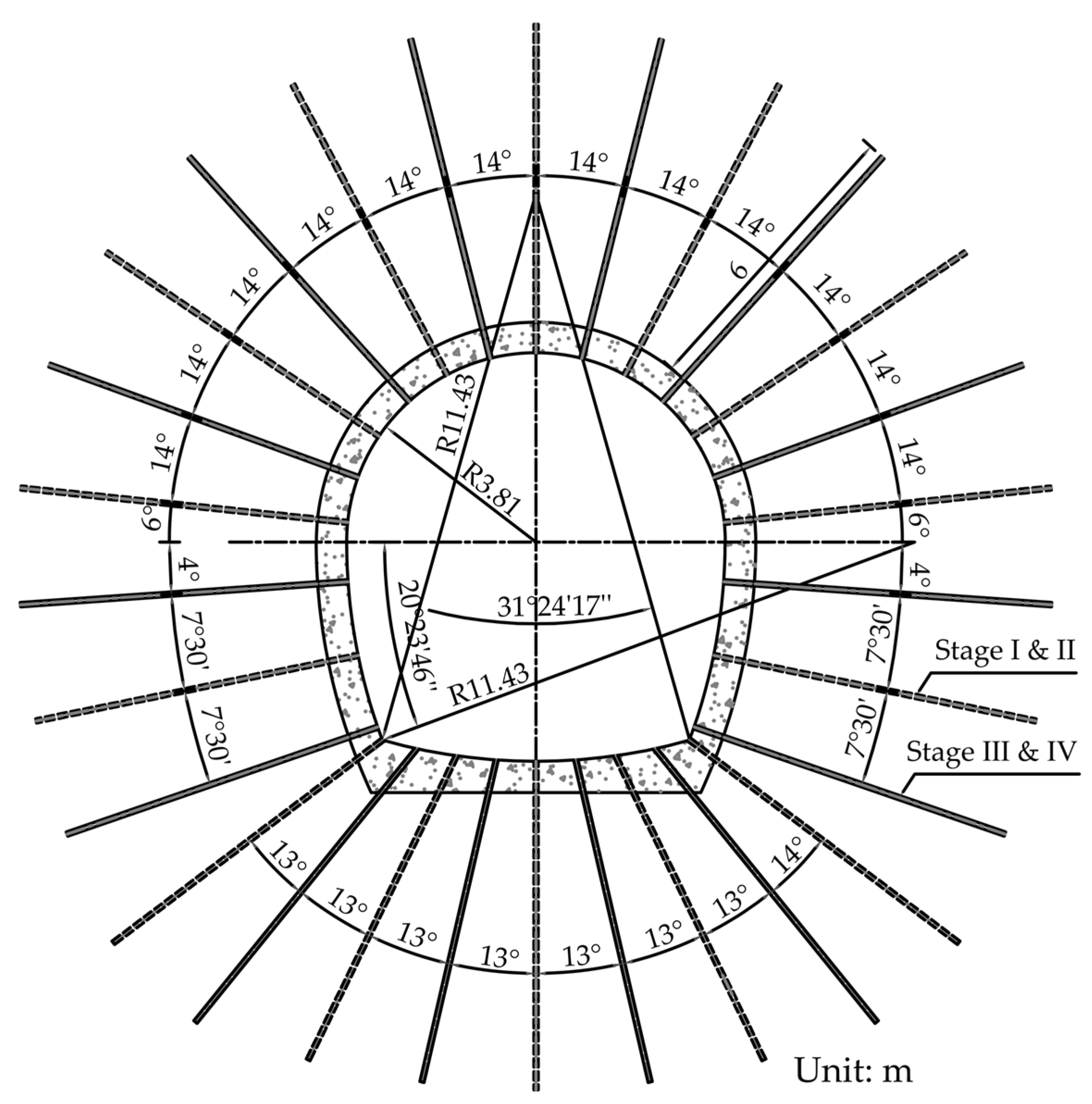
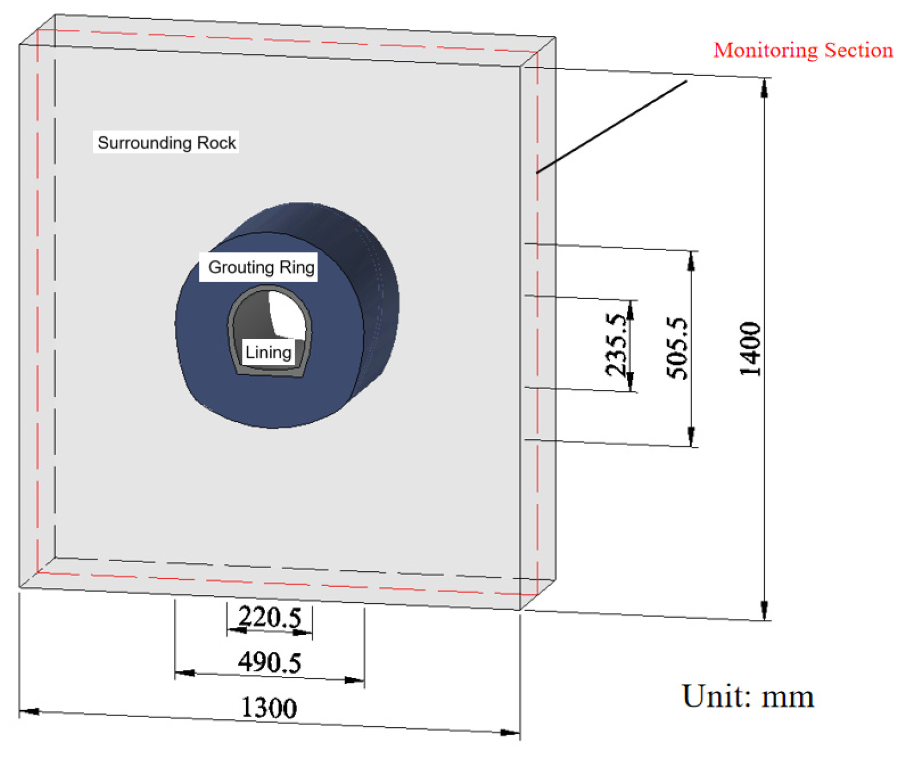
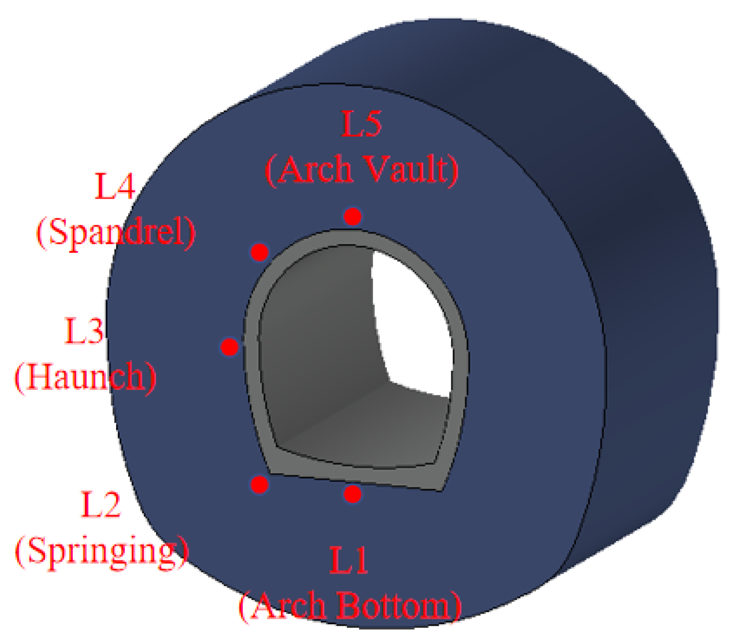
3.1. Experimental Design
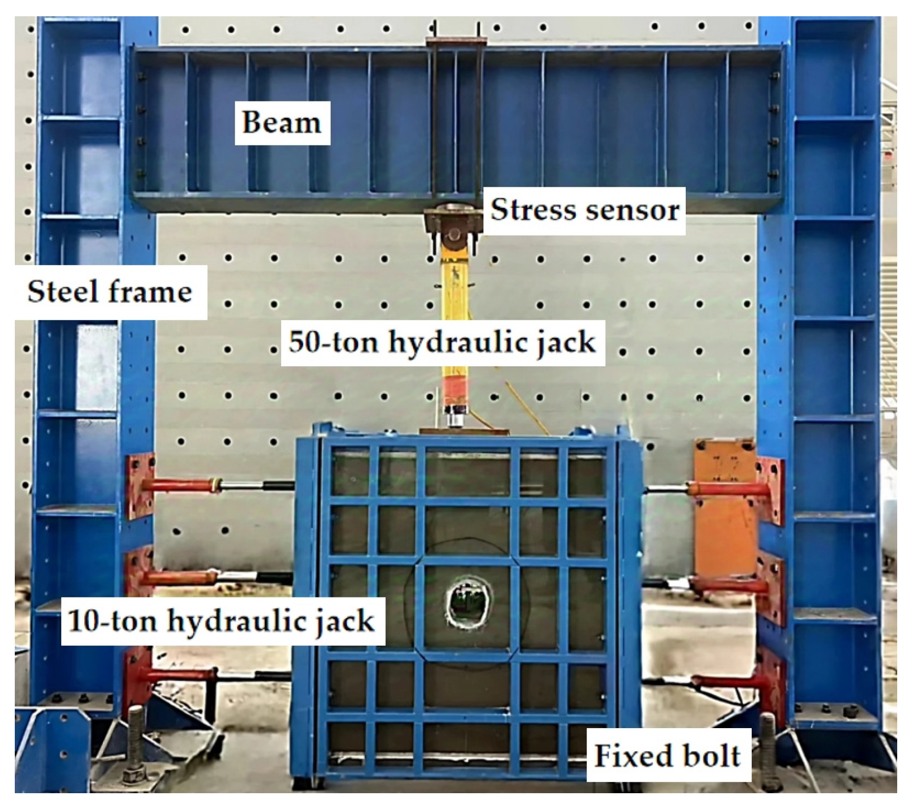
A typical cross-section was selected for the model experiment. This section consists of light gray and gray-white thin-bedded dolomite interbedded with dark gray argillaceous dolomite from the Sinian System Dengying Formation (Zbdn).
The designed excavation section of the Songlin Tunnel measures 8.82 m in width and 9.42 m in height and has a lining thickness of 0.6 m. Six-meter-long grouting pipes are arranged around the tunnel, as shown in Figure 2. The grouting is carried out in stages, with Stages I and II followed by Stages III and IV. Under drained conditions, 0.5 m diameter drainage holes are placed at 3 m intervals at the haunches on both sides of the lining. The 1:40 scale model of the Songlin Tunnel is shown in Figure 3.
The cross-section is located below the groundwater level, with an aquifer thickness of approximately 120 m. Groundwater is present in bedrock fractures and fault water-bearing zones. The maximum horizontal principal stress of the tunnel rock mass ranges from 6.8 MPa to 11.1 MPa, the minimum horizontal principal stress ranges from 4.6 MPa to 7.2 MPa, and the vertical stress ranges from 6.8 MPa to 9.6 MPa. The lateral pressure coefficient in the direction of the maximum horizontal principal stress typically approximates 1.0.
The experimental loading schemes, as detailed in Table 1, are designed based on the tunnel depth, water head, and drainage conditions.
A monitoring section was set up in the middle of the model, with seepage pressure sensors installed on the left side of the lining, as shown in Figure 3. The layout of the measurement points is illustrated in Figure 4.

3.2. Loading System

A geomechanical model experimental system was developed to study high external water pressure on the tunnel’s composite system, as shown in Figure 5. The geomechanical model experimental system consists of four main parts: a visualized model experimental frame, a stress loading system, a seepage pressure loading system, and a monitoring and data collection system.
The experimental model dimensions are 1.3 m × 1.4 m × 0.4 m, constructed from steel plates and acrylic sheets, with bolted sides and thick rubber gaskets for sealing and lateral loading. Sealing rubber gaskets are also set at the top and bottom to ensure sealing and prevent seepage under high pressure.
The stress loading system, using a 50-ton jack at the top and six 10-ton side jacks, applies stress in a trapezoidal distribution. The seepage pressure loading system consists of a constant pressure control system and pressurized pipelines. The constant pressure control system employs variable frequency technology to accurately maintain and adjust the water pressure loads corresponding to the water heads ranging from 1 m to 50 m. The experimental bench is linked to the seepage pressure loading system via pipelines. The section of the pressurized pipeline that extends into the model domain is equipped with multiple injection ports, each protected by fine mesh filters. These filters effectively prevent the intrusion of particles from the model materials, ensuring the uninterrupted operation of the network. The hydraulic network, which includes four independently controlled pressure pipelines, supplies water to the injection ports, creating the precise seepage pressure conditions necessary for the experimental investigation. The data collection system, with 40 channels, automatically collects stress and seepage pressure data via sensors connected to a computer.

3.3. Model Materials

Based on fluid–solid coupling theory, the geometric similarity ratio CL = 1:40 and the weight similarity ratio Cγ = 1 were selected as the fundamental similarity ratios. The derived similarity ratios included the stress similarity ratio Cσ = 1:40, elastic modulus similarity ratio CE = 1:40, and permeability coefficient similarity ratio CK = 1 : 2 10 .
The material mix ratios employed in this study follow the formulations presented by Wang et al. [32], ensuring consistency and comparability with prior research. A series of physical and mechanical tests were independently conducted. The density, uniaxial compressive strength, elastic modulus, and permeability coefficient for each mix ratio used were measured by uniaxial compressions and permeability tests. According to the test results and the mechanical parameters of the rock and grouting ring in the Songlin Tunnel, similar material ratios and parameters for the surrounding rock and the grouting ring were selected, as shown in Table 2 and Table 3.

4. Analysis of Model Experimental Results

The distribution of external water pressure under both undrained and drained conditions is analyzed in this section. The influence of the tunnel depth, water head, and drainage measures on the mechanical behavior of the lining is investigated at key locations, including the arch bottom (L1), springing (L2), haunch (L3), spandrels (L4), and arch vault (L5). The external water pressure values at these critical points under both conditions are detailed in Table 4.

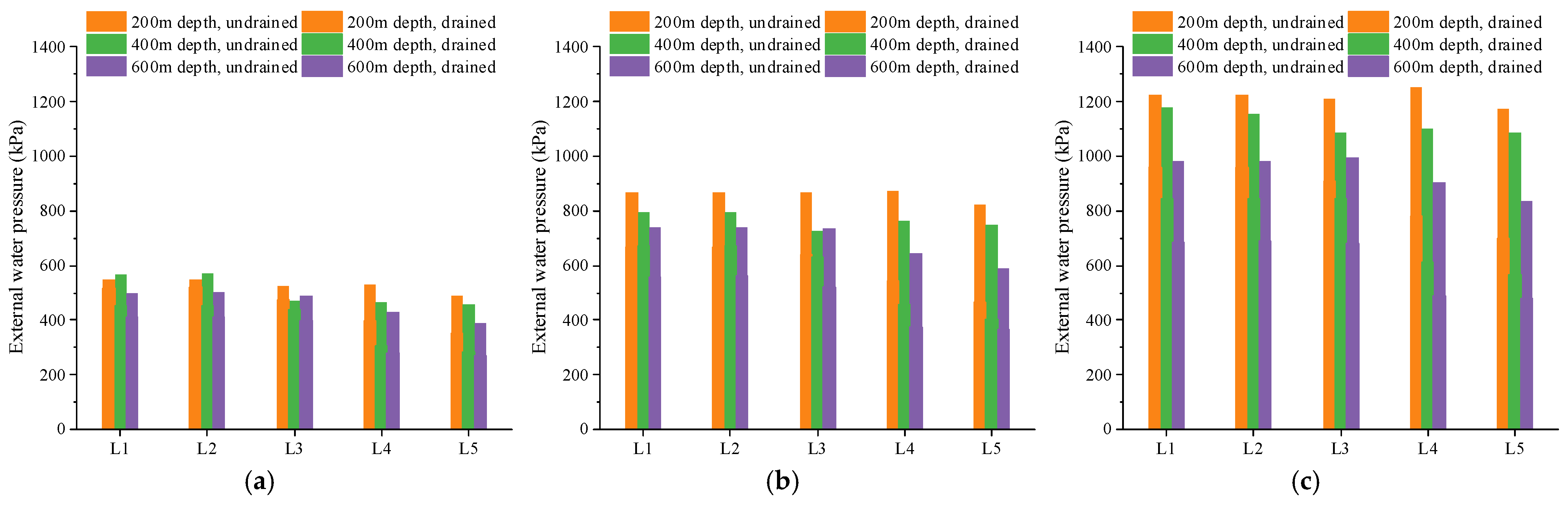
4.1. Influence of Tunnel Depth

The external water pressure under different tunnel depths is shown in Figure 6. As the tunnel depth increases, the overlying rock exerts greater compaction on the lower layers, resulting in a reduction in fractures and pores within the rock. The consequent reduction in rock permeability gradually decreases the external water pressure on the lining. The reduction in external water pressure becomes more pronounced with an increasing tunnel depth, especially under higher water heads. For instance, under an undrained condition with a water head of 80 m, the average external water pressure at 600 m depth is 66 kPa lower than at 200 m depth, a 12.6% reduction. With a water head of 160 m, the average external water pressure at a 600 m depth is 276 kPa lower than at a 200 m depth, a 22.7% reduction. Under low water head conditions, the small hydraulic gradient results in limited effects on the water flow path, as pressure variations are insignificant. However, at high water heads, increased stress reduces the permeability and effectively increases water flow resistance, significantly lowering the water pressure. Under drained conditions, the drainage measures significantly reduce the external water pressure, with the reduction effect more pronounced at greater tunnel depths. The drainage effect is more significant at higher depths due to the increased effectiveness of drainage measures in reducing fractures and pore pressure.

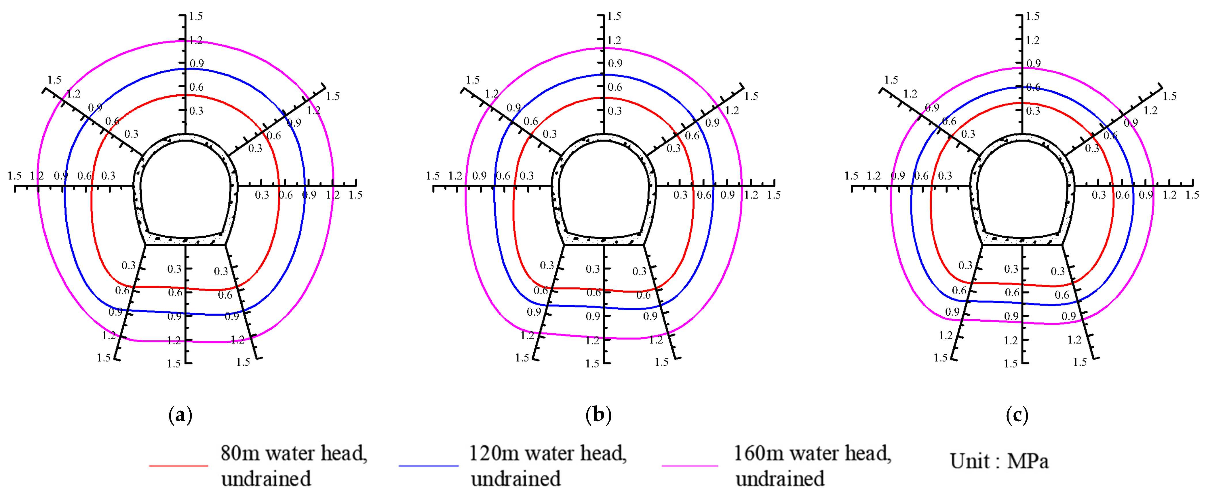
4.2. Influence of Water Head

To reveal the pattern of external water pressure around the tunnel under different water heads, the external water pressure envelope was plotted and analyzed. To construct the envelope diagrams of external water pressure, a coordinate system was established perpendicular to the lining surface, oriented outward toward the grouting ring. Experimental data were recorded at discrete measurement points located at key positions (arch bottom, springing, haunch, spandrels, and arch vault) along the tunnel lining. External water pressures measured at these points under groundwater heads of 80 m, 120 m, and 160 m were plotted on these coordinates. Finally, spline interpolation was employed to smoothly connect these discrete points, forming envelope diagrams that visually represent the external water pressure distribution around the tunnel lining under different groundwater head conditions. The envelope diagrams of external water pressure under undrained conditions are shown in Figure 7. At tunnel depths of 200 m, 400 m, and 600 m, the increase in water head from 80 m to 120 m results in average increases in external water pressure of 330.9 kPa, 259.0 kPa, and 227.8 kPa, respectively. When the water head increases from 120 m to 160 m, the average increases in external water pressure are 358.1 kPa, 356.5 kPa, and 251.3 kPa, respectively. The pressure increase is more significant from a 120 m to 160 m water head than from an 80 m to 120 m water head. High water pressure expands the rock pores and fractures, forming seepage channels and reducing the sealing effect of the surrounding rock and grouting ring. Therefore, higher water heads result in more substantial pressure increases.
The envelope diagrams of external water pressure under drained conditions are shown in Figure 8. Under drained conditions at depths of 200 m, 400 m, and 600 m, increasing the water head from 80 m to 120 m led to average external water pressure rises of 144.9 kPa, 179.8 kPa, and 123.3 kPa, respectively. When the water head further increased from 120 m to 160 m, the average pressure increases were 265.0 kPa, 175.4 kPa, and 129.1 kPa, corresponding to the same depth order. Under low water head conditions, the external water pressure is primarily influenced by the water head, with little effect from the tunnel depth. However, from a 120 m to 160 m water head, there is a clear negative correlation between the pressure increase and tunnel depth.

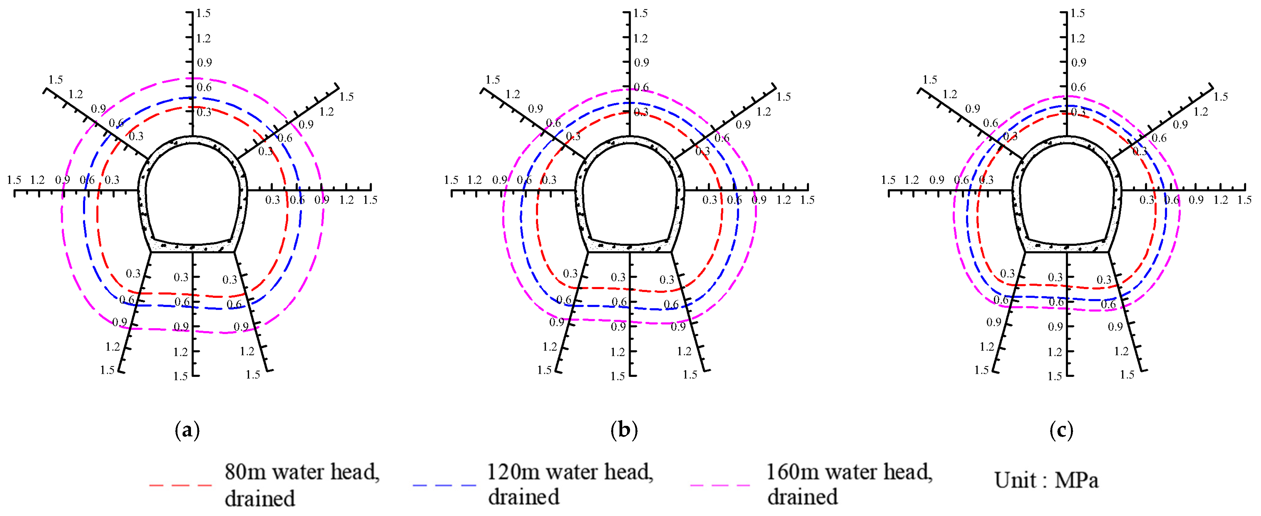
4.3. Influence of Drainage Conditions

Table 5 shows the changes in the external water pressure rates at various positions of the lining post-drainage. The results indicate that drainage holes reduce external water pressure across all tunnel sections, though the extent of the reduction varies significantly. The arch vault and spandrel experience the most substantial pressure reduction, ranging from 24.7% to 48.0%, with an average decrease of 38.1%. In contrast, the haunch, springing, and arch bottom show a lower average reduction of 20.5%.
Under high water head conditions, drainage measures significantly reduce the external water pressure at various tunnel locations. This is attributed to the expansion of rock mass fractures caused by high water pressure, which increases rock permeability and facilitates groundwater flow toward the drainage holes. Conversely, under low water head conditions, the low permeability of the grouting ring restricts the drainage range to the vicinity of the drainage holes.

4.4. Discussion on Reduction Coefficient Values

In tunnel engineering design and construction, the reduction coefficient method is widely used to calculate external water pressure. This study provides reduction coefficients derived from geomechanical model experiments, as shown in Table 6 and Table 7.
Under undrained conditions, the reduction coefficients of external water pressure are relatively high, ranging approximately between 0.52 and 0.80, with no significant differences observed across various lining locations. This observation indicates that without drainage measures, the external water pressure tends to be uniformly distributed around the lining structure, primarily influenced by hydrostatic pressure and rock permeability characteristics. At tunnel depths of 200 m, 400 m, and 600 m, the average reduction coefficients are 0.71, 0.66, and 0.58, respectively, indicating a decrease with increasing tunnel depth. This phenomenon can be explained by the increased stress at greater depths compressing rock fractures and pores, reducing rock mass permeability, thereby limiting groundwater infiltration and effectively decreasing the external water pressure on the lining. Additionally, the reduction coefficient slightly increases with higher water heads, averaging 0.62, 0.64, and 0.68 at water heads of 80 m, 120 m, and 160 m, respectively.
Based on these findings, it is recommended to set the reduction coefficient for external water pressure between 0.65 and 0.80 for shallowly buried tunnels under high water heads and between 0.50 and 0.65 for deeply buried tunnels under low water heads.
Table 7 provides reduction coefficients under drained conditions, revealing a notable impact of the drainage measures on external water pressure. In particular, coefficients at the haunch, arch springing, and arch bottom are generally higher compared to those at the arch vault and spandrels, indicating more effective drainage at the upper and side areas of the tunnel lining. The coefficients for the arch vault and spandrels show heightened sensitivity to an increasing tunnel depth, dropping significantly by approximately 0.15 to 0.19 when the depth increases from 200 m to 600 m under identical water head conditions. This behavior can be attributed to the enhanced efficiency of drainage measures at greater depths due to the lower permeability of the surrounding rock and grouting ring at these depths, effectively lowering groundwater infiltration into these regions.
Considering these findings, the recommended reduction coefficients for designing tunnel linings under drained conditions are between 0.30 and 0.55 for the arch vault and spandrels. Meanwhile, for regions such as the haunch, arch springing, and arch bottom, slightly higher reduction coefficients, ranging from 0.50 to 0.60 under lower water head conditions and from 0.40 to 0.60 under higher water head conditions, are suggested.

5. Conclusions

A geomechanical model experiment on external water pressure was conducted using a self-developed system based on a typical section of the Songlin Tunnel from the Central Yunnan Water Diversion Project. The main conclusions are as follows:
1.
The geomechanical model system was developed to investigate high external water pressure under complex geological conditions. This system includes a waterproof model framework, a stress loading system, a seepage pressure loading system, and a monitoring and data acquisition system. The system meets the waterproofing requirements and provides constant pressure.
2.
The model experiments revealed the distribution pattern of external water pressure in the Songlin Tunnel. Under undrained conditions, the external water pressure is mainly controlled by the water head and tunnel depth. At low water heads, the tunnel depth has little effect on the external water pressure. At a water head of 160 m, the external water pressure significantly decreases with an increasing tunnel depth.
3.
For undrained conditions, the reduction coefficients decrease with increasing tunnel depth and slightly increase with higher water heads. The suggested coefficients are 0.65–0.80 for shallowly buried tunnels with high water heads and 0.50–0.65 for deeply buried tunnels with low water heads. For drained conditions, the recommended reduction coefficients are 0.30–0.55 for the arch vault and spandrels. For the haunch, arch springing, and arch bottom, the suggested coefficients are 0.50 to 0.60 under the low water head and 0.40 to 0.60 under the high water head.

Author Contributions

Conceptualization, W.X. and W.H.; methodology, W.X. and J.Z.; validation, R.W., W.H. and J.Z.; investigation, W.H. and J.Z.; resources, R.W. and W.X.; data curation, W.H. and J.Z.; writing—original draft preparation, W.H. and J.Z.; writing—review and editing, M.H. and W.X.; visualization, W.H. and M.H.; supervision, W.X. and R.W.; project administration, W.X.; funding acquisition, R.W. and W.X. All authors have read and agreed to the published version of the manuscript.

Funding

This research is supported by the Key Science and Technology Special Program of Yunnan province (No. 202102AF080001).

Data Availability Statement

All data, models, or codes that support the findings of this study are available from the corresponding author upon reasonable request.

Conflicts of Interest

The authors declare no conflicts of interest.

References

  1. Peng, Y.; Cao, C.; Ji, F.; Chen, X. Water inrush-induced failure during deep excavation for a metro station in karst regions in Shenzhen, China: Cause diagnosis and post-accident restoration. Eng. Fail. Anal. 2024, 162, 108346. [Google Scholar] [CrossRef]
  2. Huang, W.; Sun, W.; Zhang, J.; Wang, Y.; Zhang, Y.; Xu, W. Research review on high external water pressure of deep-buried tunnels. J. China Three Gorges Univ. Nat. Sci. 2023, 45, 1–11. [Google Scholar] [CrossRef]
  3. Zhang, D.M.; Xie, X.C.; Zhou, M.L.; Huang, Z.K.; Zhang, D.M. An incident of water and soil gushing in a metro tunnel due to high water pressure in sandy silt. Eng. Fail. Anal. 2021, 121, 105196. [Google Scholar] [CrossRef]
  4. Ma, Y.; Che, Y.; Gong, J. Behavior of corrosion damaged circular reinforced concrete columns under cyclic loading. Constr. Build. Mater. 2012, 29, 548–556. [Google Scholar] [CrossRef]
  5. Yang, J.; Fu, W.; Hu, X.; Liu, C.; Yang, Q.; Ju, J.W. Experimental study on the long-term behaviors of spray-applied acrylate waterproofing membrane for tunnels exposed to aggressive ions. Constr. Build. Mater. 2020, 258, 119603. [Google Scholar] [CrossRef]
  6. Bobet, A. Analytical solutions for shallow tunnels in saturated ground. J. Eng. Mech. 2001, 127, 1258–1266. [Google Scholar] [CrossRef]
  7. Bobet, A. Effect of pore water pressure on tunnel support during static and seismic loading. Tunn. Undergr. Space Technol. 2003, 18, 377–393. [Google Scholar] [CrossRef]
  8. Nam, S.W.; Bobet, A. Liner stresses in deep tunnels below the water table. Tunn. Undergr. Space Technol. 2006, 21, 626–635. [Google Scholar] [CrossRef]
  9. Duan, S.; Jiang, X.; Jiang, Q.; Xiong, J.; Li, C. Theoretical solution and failure analysis of water pressure on lining of deep-buried non-circular hydraulic tunnel based on the equivalent hydraulic radius method. Eng. Fail. Anal. 2023, 148, 107163. [Google Scholar] [CrossRef]
  10. Shin, J.; Shin, Y.; Kim, S.; Shin, H. Evaluation of residual pore water pressures on linings for undersea tunnels. Chin. J. Rock Mech. Eng. 2007, 26, 3682–3685. [Google Scholar]
  11. Wang, X.Y.; Wang, M.S.; Zhang, M. A simple method to calculate tunnel discharge and external water pressure on lining. J. Beijing Jiaotong Univ. 2004, 28, 8–10. [Google Scholar]
  12. Kolymbas, D.; Wagner, P. Groundwater ingress to tunnels: The exact analytical solution. Tunn. Undergr. Space Technol. 2007, 22, 23–27. [Google Scholar] [CrossRef]
  13. Shen, J.; Ma, H.; Du, H.; Xin, Y.; Liu, H.; Ma, W. Numerical Simulation of the External Water Pressure in Seepage Anisotropy Under Heterogeneous Conditions. Water 2024, 16, 3173. [Google Scholar] [CrossRef]
  14. Schwartz, F.W.; Sudicky, E.A.; McLaren, R.G.; Park, Y.J.; Huber, M.; Apted, M. Ambiguous hydraulic heads and 14C activities in transient regional flow. Groundwater 2010, 48, 366–379. [Google Scholar] [CrossRef]
  15. Xie, X.; Xie, X.; Wang, X.; Lu, B.; Chen, H. Influences of aquiclude on external water pressures on linings of deep-buried tunnels. Chin. J. Geotech. Eng. 2020, 42, 146–150. [Google Scholar] [CrossRef]
  16. Long, C.S.; Wilson, C.R.; Witherspoon, P. Porous media equivalents for networks of discontinuous fractures. Water Resour. Res. 1982, 18, 645–658. [Google Scholar] [CrossRef]
  17. Cacas, M.C.; Ledoux, E.; Marsily, G.; Tillie, B.; Barbreau, A.; Durand, E.; Feuga, P.; Peaudecerf, P. Modeling fracture flow with a stochastic discrete fracture network: Calibration and validation: 1. the flow model. Water Resour. Res. 1990, 26, 479–489. [Google Scholar] [CrossRef]
  18. Huang, Y.; Fu, Z.; Chen, J.; Liu, X. The external water pressure on a deep buried tunnel in fractured rock. Tunn. Undergr. Space Technol. 2015, 48, 58–66. [Google Scholar] [CrossRef]
  19. Xiong, F.; Zhu, C.; Feng, G.; Zheng, J.; Sun, H. A three-dimensional coupled thermo-hydro model for geothermal development in discrete fracture networks of hot dry rock reservoirs. Gondwana Res. 2023, 122, 331–347. [Google Scholar] [CrossRef]
  20. Shin, J.; Potts, D.; Zdravkovic, L. The effect of pore-water pressure on NATM tunnel linings in decomposed granite soil. Can. Geotech. J. 2005, 42, 1585–1599. [Google Scholar] [CrossRef]
  21. Arjnoi, P.; Jeong, J.H.; Kim, C.Y.; Lee, J.Y. Effect of drained conditions on porewater pressure distributions and lining stresses in drained tunnels. Tunn. Undergr. Space Technol. 2009, 24, 376–389. [Google Scholar] [CrossRef]
  22. Li, L.; Yang, J.; Fu, J.; Wang, S.; Zhang, C.; Xiang, M. Experimental investigation on the invert stability of operating railway tunnels with different drainage systems using 3D printing technology. J. Rock Mech. Geotech. Eng. 2022, 14, 1470–1485. [Google Scholar] [CrossRef]
  23. Fang, Y.; Guo, J.; Grasmick, J.; Zhang, H. The effect of external water pressure on the liner behavior of large cross-section tunnels. Tunn. Undergr. Space Technol. 2016, 60, 80–95. [Google Scholar] [CrossRef]
  24. Fan, H.; Zhu, Z.; Song, Y.; Li, B. Water pressure evolution and structural failure characteristics of tunnel lining under hydrodynamic pressure. Eng. Fail. Anal. 2021, 130, 105747. [Google Scholar] [CrossRef]
  25. Li, P.; Feng, C.; Liu, H.; Zhao, Z.; Li, Y.; Xiong, H. Development and assessment of a water pressure reduction system for lining invert of underwater tunnels. Mar. Georesour. Geotechnol. 2021, 39, 365–371. [Google Scholar] [CrossRef]
  26. Wang, X.; Tan, Z.; Wang, M.; Huangfu, M.; Zhang, Z. Theoretical and experimental study of external water pressure on tunnel lining in controlled drainage under high water level. Tunn. Undergr. Space Technol. 2008, 23, 552–560. [Google Scholar] [CrossRef]
  27. Qian, W.P.; Wang, B.; Luo, D.W.; Xu, A.; Li, S.C. Experimental investigation and application on mechanical properties of tunnel linings under different blockage rates of drainage system in a karst tunnel. Tunn. Undergr. Space Technol. 2025, 157, 106359. [Google Scholar] [CrossRef]
  28. Yang, G.; Yang, X.; Zhang, J.; He, M.; Hao, Z.; Yang, F.; Shao, J. Effect of Roof Cutting Technology on Broken Roof Rock Bulking and Abutment Stress Distribution: A Physical Model Test. Rock Mech. Rock Eng. 2024, 57, 3767–3785. [Google Scholar] [CrossRef]
  29. He, B.; Xue, R.; Zhang, Z.; Feng, X.; Wu, C. A novel method of imposing external water pressure to explore the failure behavior of railway tunnel linings. Tunn. Undergr. Space Technol. 2023, 133, 104942. [Google Scholar] [CrossRef]
  30. Jiang, Y.; Zhou, F.; Lin, J.; Li, J.; Qi, Y.; Wang, X.; Zhou, Z. Evolution mechanism of tunnel water and sand inrush considering water-rich sandy dolomite hazard-causing structures. Eng. Fail. Anal. 2023, 153, 107554. [Google Scholar] [CrossRef]
  31. He, B.; Zhang, Z.; Xue, B.; He, X.; Feng, Z.; Sun, C. Model test on the behavior of tunnel linings under earth pressure conditions and external water pressure. Transp. Geotech. 2021, 26, 100457. [Google Scholar] [CrossRef]
  32. Wang, R.; Wang, X.; Zhang, W.; Xu, W.; Lu, J.; Xiang, T. Physical model experiment of external water pressure in lining surrounding rock of a deep tunnel with cross faults. J. Tsinghua Univ. Sci. Technol. 2024, 64, 1179–1192. [Google Scholar] [CrossRef]
Figure 1. Water gushing from the large pipe shed in the Songlin Tunnel.
Water 17 00913 g001
Figure 2. Cross-Section of consolidation grouting in the Songlin Tunnel.
Water 17 00913 g002
Figure 3. Geomechanical model of the typical cross-section of the Songlin Tunnel.
Water 17 00913 g003
Figure 4. Layout of external water pressure monitoring points.
Water 17 00913 g004
Figure 5. High external water pressure geomechanical model experimental system.
Water 17 00913 g005
Figure 6. Distribution of external water pressure at different water heads on various parts of the lining: (a) 80 m water head; (b) 120 m water head; (c) 160 m water head.
Water 17 00913 g006
Figure 7. Envelope diagrams of external water pressure on the lining under undrained conditions: (a) 200 m tunnel depth; (b) 400 m tunnel depth; (c) 600 m tunnel depth.
Water 17 00913 g007
Figure 8. Envelope diagrams of external water pressure on the lining under drained conditions: (a) 200 m tunnel depth; (b) 400 m tunnel depth; (c) 600 m tunnel depth.
Water 17 00913 g008
Table 1. Experimental loading scheme.
SchemeDrainage ConditionTunnel Depth (m)Water Head (m)
1Undrained20080
2120
3160
440080
5120
6160
760080
8120
9160
10Drained *20080
11120
12160
1340080
14120
15160
1660080
17120
18160
Note: * The drainage conditions are achieved through drainage holes in the lining and a capillary drainage network at the top of the lining, which facilitate tunnel drainage.
Table 2. Mixture ratios of model materials for surrounding rock and grouting ring of the tunnel.
MaterialIron PowderQuartz Sand (%)Barite Powder (%)White Cement (%)Silicone Oil (%)Water (%)
Surrounding Rock25.0922.9936.268.661.215.78
Grouting Ring31.3426.5923.0711.250.267.49
Table 3. Mechanical parameters of similar materials for surrounding rock and grouting ring of the tunnel.
Model ComponentDensity
(g·cm−3)
Elastic Modulus
(GPa)
Permeability Coefficient
(10−5 cm·s−1)
Surrounding Rock2.682.315.70
Grouting Ring2.833.401.70
Table 4. External water pressure at key lining locations under undrained and drained conditions.
Water
Head
(m)
Tunnel
Depth (m)
Arch Bottom
(L1)/kPa
Springing
(L2)/kPa
Haunch
(L3)/kPa
Spandrels
(L4)/kPa
Arch Vault
(L5)/kPa
UndrainedDrainedUndrainedDrainedUndrainedDrainedUndrainedDrainedUndrainedDrained
80200549518549519524475528397489351
400866667867668866641873542822466
60012239581224960121291112517811174699
120200569452570453470438468308456282
400794671795673725629764458749402
60011778431158845108984511016101086565
160200500411501412487396430277390269
400739560740561735519643375590367
600983687983688996682907490834481
Table 5. Changes in external water pressure rates at various positions of the lining post-drainage.
Water Head
(m)
Tunnel Depth
(m)
Arch Bottom
(L1)/%
Springing
(L2)/%
Haunch
(L3)/%
Spandrels
(L4)/%
Arch Vault
(L5)/%
802005.7 5.5 9.4 24.7 28.3
40020.6 20.5 6.9 34.1 38.2
60017.7 17.6 18.7 35.6 31.0
12020023.1 22.9 25.9 37.9 43.3
40015.5 15.4 13.3 40.1 46.4
60024.3 24.1 29.4 41.6 37.7
16020021.7 21.6 24.8 37.5 40.5
40028.4 27.0 22.4 44.6 48.0
60030.1 30.0 31.5 46.0 42.3
Table 6. Reduction coefficients of external water pressure under undrained conditions.
Water Head
(m)
Tunnel Depth
(m)
Arch Bottom
(L1)
Springing
(L2)
Haunch
(L3)
Spandrels
(L4)
Arch Vault
(L5)
802000.65 0.65 0.66 0.69 0.66
4000.67 0.67 0.59 0.61 0.61
6000.59 0.59 0.61 0.56 0.52
1202000.69 0.69 0.72 0.75 0.72
4000.64 0.64 0.61 0.66 0.65
6000.59 0.59 0.61 0.55 0.52
1602000.74 0.74 0.76 0.80 0.76
4000.71 0.70 0.68 0.70 0.70
6000.60 0.60 0.62 0.58 0.54
Table 7. Reduction coefficients of external water pressure under drained conditions.
Water Head (m)Tunnel Depth (m)Arch Bottom (L1)Springing (L2)Haunch (L3)Spandrels (L4)Arch Vault (L5)
802000.61 0.61 0.60 0.52 0.47
4000.53 0.53 0.55 0.40 0.38
6000.48 0.49 0.50 0.36 0.36
1202000.53 0.53 0.54 0.47 0.41
4000.54 0.54 0.53 0.39 0.35
6000.45 0.45 0.43 0.32 0.32
1602000.58 0.58 0.57 0.50 0.45
4000.51 0.51 0.53 0.39 0.37
6000.42 0.42 0.43 0.31 0.31
Disclaimer/Publisher’s Note: The statements, opinions and data contained in all publications are solely those of the individual author(s) and contributor(s) and not of MDPI and/or the editor(s). MDPI and/or the editor(s) disclaim responsibility for any injury to people or property resulting from any ideas, methods, instructions or products referred to in the content.

