Article

Simulink Implementation of a Hydrologic Model: A Tank Model Case Study

1
Research Institute for Agriculture and Life Sciences, Seoul National University, Seoul 08826, Korea
2
Department of Agricultural and Biological Engineering and Tropical Research and Education Center, University of Florida, Homestead, FL 33186, USA
3
Climate Application Department, APEC Climate Center, Busan 48058, Korea
4
National Institute of Agriculture Science, Rural Development Administration, Wanju, Jeollabuk-do 55365, Korea
5
Department of Rural Systems Engineering, Research Institute for Agriculture and Life Sciences, Institute of Green Bio Science and Technology, Seoul National University, Seoul 08826, Korea
*
Author to whom correspondence should be addressed.
Water 2017, 9(9), 639; https://doi.org/10.3390/w9090639
Submission received: 15 June 2017 / Revised: 19 August 2017 / Accepted: 22 August 2017 / Published: 25 August 2017

Abstract

:
Simulink, an extension of MATLAB, is a graphics-based model development environment for system modeling and simulation. Simulink’s user-friendly features, including block (data process) and arrow (data transfer) objects, a large number of existing blocks, no need to write codes, and a drag and drop interface, provide modelers with an easy development environment. In this study, a Tank model was developed using Simulink and applied to a rainfall-runoff simulation for a study watershed to demonstrate the potential of Simulink as a tool for hydrological analysis. In the example given here, the Tank model was extended by two sub-modules representing evapotranspiration and storage-runoff distribution. In addition, model pre- and post-processing, such as input data preparation and results plotting, was carried out in MATLAB. Moreover, model parameters were calibrated using MATLAB optimization tools without any additional programming for linking the calibration algorithms and the model. The graphical representation utilized in the Simulink version of the Tank model helped us to understand the hydrological interactions described in the model, and the modular structure of the program facilitated the addition of new modules and the modification of existing modules as needed. From the study, we found that Simulink could be a useful and convenient environment for hydrological analysis and model development.

1. Introduction

The rainfall-runoff process is highly nonlinear, time varying, and spatially heterogeneous; thus, hydrological analysis frequently uses simulation models to describe and predict watershed responses to rainfall events based on mathematical and physical knowledge. Hydrological models are also commonly used to explore options to manage water resources at point, field, and watershed scales. Accordingly, water management studies have led to the development of numerous hydrologic models [1,2]. Many distinct model-building paradigms have been proposed depending on the consideration of spatial variability, ranging from lumped models, such as the Tank model [3], Hydrologiske Byrån avdeling för Vattenbalans (HBV) [4], HYdrological MODel (HYMOD) [5], and Xinanjiang [6] to physical-based distributed models, such as Systeme Hydrologique Europeen (SHE) [7], AGricultural Non-Point Source Pollution Model (AGNPS) [8], and Areal Non point Source Watershed Environment Response Simulation (ANSWERS) [9]. It is sometimes beneficial to use less complex and less computationally-demanding models, for first-order analyses, for instance, or to run a large number of test cases [10,11]. For practical applications, such as risk analysis, the performance of lumped conceptual models may serve as a benchmark for sophisticated models to determine their added value, and hence their suitability for a particular case [11,12,13]. From this perspective, this paper focuses on lumped hydrological models that approximate general physical mechanisms governing hydrological processes, which may be less demanding in terms of model input [14].
A hydrological model developed for a specific watershed can be applied to another one as long as the model is capable of describing the hydrologic processes of interest. However, it is often the case that existing models are not comprehensive enough to account for the unique hydrological features of a new study watershed. Many researchers have tried to tackle this issue by developing modular modeling software or a framework [2]. Such a framework is usually based on object-based concepts [15,16] in which individual model parts, or “modules” are designed to encapsulate a single idea, delivering flexibility and encouraging module reuse [16,17,18,19]. Within different modeling spectra, including discrete time and entities, many problems and modeling tools are amenable to approaches based on object theory and are readily addressed using appropriate software engineering designs and development methods [4]. Modeling frameworks have been developed based on such concepts that permit the selective use of module libraries and possess model architectures that can be customized to address a range of environmental problems [2,16,20,21,22,23].
Simulink, a MATLAB extension, (MathWorks, Natick, MA, USA) is one of the most popular simulation tools used in the system engineering community [24]. Simulink provides a drag-drop graphical user interface (GUI) that allows models to be built as “block” and “arrow” diagrams, and lets users create blocks by copying block-type exemplars stored in libraries [25,26]. The Simulink block library is extensive, including math and logic functions, signal generation and processing, visualization, and many specialized toolboxes such as fuzzy logic, DSP, control systems, and neural networks [26]. By facilitating the reuse of common block elements, Simulink eliminates the need to write thousands of lines of computer codes for model development, significantly decreasing the time required to create new models and improve existing ones [25,26].
Although Simulink has been adopted in various engineering fields as a means of modeling complex systems, its use in hydrologic system modeling has been limited [26,27,28,29,30]. As Simulink can schematically illustrate dynamic linkage between hydrologic components such as rainfall, interception, storage, evapotranspiration, and runoff, it can be useful for rainfall-runoff modeling. The modular design and extensive block library can help modelers focus on hydrological analysis including modeling strategy development, parameter estimation, and model application. In this study, we explore the potential benefits of using Simulink as a tool for hydrological model development and analysis. The Tank model, widely used in rainfall-runoff modeling, was selected as an example of a hydrological model to be developed using Simulink in this case study.

2. Materials and Methods

2.1. Simulink Modeling Framework

Simulink is a graphical programming environment for modeling that enables the dynamic analysis of data processing [31]. This high-level programming language is convenient and powerful due to its graphical interface and modularity, which allows easy insertion and deletion of modules [15].
Simulink creates a model by connecting iconized blocks, which is accomplished by dragging blocks from Simulink Editor to the workspace. The mathematical relationships between the blocks are defined using arrow diagrams (Figure 1). Blocks and arrows built by users can be grouped together into a subsystem (or module), forming a single-objective model with inputs and outputs corresponding to its structure [31].
After modules are developed for each simulation mechanism, the user can easily create a customized model by importing the desired modules and defining the relationships between those modules. Hence, Simulink is advantageous for hierarchical and object-based modeling.
The preparation of input data and the output of simulation results are conducted in a MATLAB environment. It is convenient to use various packages that are embedded in MATLAB or shared online. Users also have access to various statistical analysis and optimization methods, such as artificial neural network (ANN), genetic algorithm (GA), simulated annealing (SA), pattern search (PS), shuffled complex evolution (SCE-UA), and particle swarm optimization (PSO), without additional programming.

2.2. The Tank Model

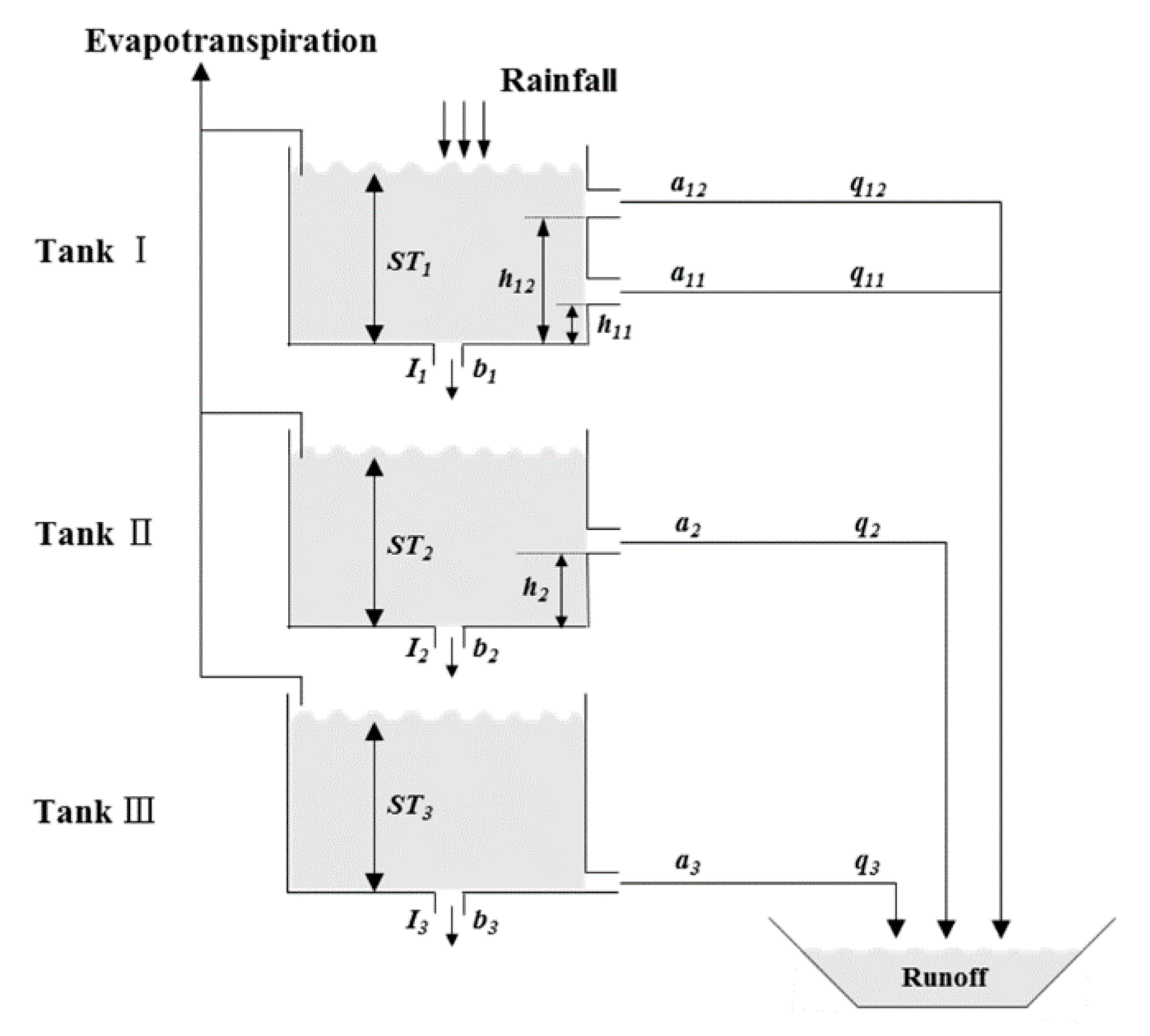
The Tank model has been widely used in rainfall-runoff modeling owing to its computational and conceptual simplicity and its forecasting accuracy [32,33,34,35]. The Tank model includes interconnections between variations in the number of tanks, side outlets, and bottom outlets, the height of the side-outlets, and the initial storage volume (Figure 2). Unlike some lumped models with parallel tanks such as HYMOD [36,37], the structure of which is conceptually realistic but difficult to observe, the movement of water between the various tanks in the Tank model always takes place in a descending direction with vertical tanks, and the total storage of the tanks represents the watershed storage. Accordingly, the structure of the Tank model is easily understandable. For a model with three tanks (3-Tank), outputs through the side outlets of the first tank (located at the top), second tank, and third tank (located at the bottom) represent surface runoff, intermediate runoff, and base flow, respectively [32,33]. The governing equations for the 3-Tank model are as follows:
Q t = q 11 + q 12 + q 2 + q 3 = i = 1 n j = 1 m ( S T i , t h i j ) a i j
I i , t = S T i , t × b i
where i is tank order, j is side-outlet order, t is time (day), n is the number of tanks, m is the number of side outlets for each tank, q i j is runoff for the j th side outlet in the i th tank, Q t is total runoff at time t , a i j is the side-outlet coefficient for the j th side outlet in the i th tank, S T i , t is the storage of the i th tank (mm), h i j is the height of side outlet for the j th side outlet in the i th tank (mm), I i , t is the infiltration in the i th tank (mm), and b i is the bottom-outlet coefficient for the i th tank. For the next time step t + 1 , the S T i , t in the tanks are calculated as follows:
S T i , t + 1 = S T i , t + P t + 1 E T i , t + 1 I i , t q i , t    for   i   =   1
S T i , t + 1 = S T i , t + I i 1 , t E T i , t + 1 I i , t q i , t    for   i   =   2 ,   3
where P t + 1 is the precipitation at time t + 1 (mm), and E T i , t + 1 is the actual evapotranspiration in the i th tank at time t + 1 (mm). The E T i , t is calculated by subtracting the evapotranspiration in the upper tanks from the total actual evapotranspiration ( E T a , t ):
E T i , t = E T a , t j = 1 i 1 E T j , t   for   E T i , t < S T i , t
E T i , t = S T i , t   for   E T i , t S T i , t .
We set the parameter ranges in the Tank model (Table 1) to the minimum and maximum values of the calibrated parameters established in [38,39], considering the watershed characteristics of Korea for 11 and 10 sites, respectively. The outflow from the third tank represents base flow, as described above, but if the water depth of the third tank does not reach the height of the side outlet ( h 3 ), base flow does not occur. Therefore, we set the height of the third tank outlet to zero so that base flow could occur continuously (Table 1).

2.3. Watershed Evapotranspiration

Lysimeter [40] and imaging techniques [41] yield the highest precision for evapotranspiration calculations, but these techniques are monetarily expensive [42]. Instead, the crop coefficient ( K c ), the soil water stress coefficient ( K s ), and potential evapotranspiration ( E T p ) can be combined to calculate the actual watershed evapotranspiration as follows [39]:
E T a , t = K c , t × K s , t × E T p , t .
The procedures for the calculation of E T p , K c , and K s are described below.

2.3.1. Potential Evapotranspiration

There are a number of methods used to estimate E T p . These methods can generally be classified as temperature-based [43,44], radiation-based [45,46], or a combination of the two [47,48,49], and they vary in terms of data requirements and accuracy. At present, the Food and Agriculture Organization of the United Nations (FAO) Penman–Monteith (PM) approach is the standard method for evapotranspiration (ET) estimation in agriculture [48]. The PM approach has been applied in several regions of the world, but it does require a great number of parameters for the estimation of E T p [42]. Fortunately, these parameters are readily obtainable in Korea, as climate data (including daily maximum and minimum temperature, relative humidity, wind speed, and solar radiation) are provided in real time at 97 weather stations by the Korean Meteorological Administration. Thus, we chose the PM approach to simulate potential evapotranspiration.

2.3.2. Crop Coefficient

The crop coefficient varies primarily with the crop species and growth characteristics [48,50]. Therefore, the value of the crop coefficient for a specific crop can usually be obtained from the literature based on its growing season and planted area. In this study, we calculated area-weighted crop coefficients ( K c , a v g ) as follows:
K c , a v g = K c , l × A l A l
where K c , l is the K c for crop l , and A l is the planted area for crop l .
Table 2 presents the crop coefficients used for each month in the PM method according to land-use type (forest, paddy, upland, and others). The forest crop coefficients are calculated by dividing the monthly E T a , which was observed over 4 years for two Korean forests [51], by E T p , which was simulated using the PM approach. The paddy crop coefficients were converted on a monthly basis from the 10-day values developed for Korean rice in [52]. The monthly upland crop coefficients were calculated using literature-recommended cultivation periods for major crops [53] and crop coefficients [48]. A coefficient of 0.20, which was proposed for bare soil [48], was applied during the non-cultivation period. The upland coefficients are area-weighted according to the cultivated area of the major crops. A crop coefficient of 0.20 was applied for the other land-use types, as they were assumed to resemble bare soil.

2.3.3. Soil Water Stress Coefficient

The following equation is used to calculate K s at the watershed scale [39]:
K s , t = 1 exp ( α × i = 1 n S T i , t ) .
As Equation (9) indicates, the value of K s is determined from the total storage of the first, second, and third tanks (i.e., the total storage of the watershed). The parameter α is related to watershed characteristics. According to [54], α has been reported to vary from 0.1 to 0.5, depending on the characteristics of the watershed, with optimization results using the water balance model for the estimation of watershed evapotranspiration. The α and K s parameters are positively correlated. Hence, an increase in α increases E T a , decreases watershed storage, and subsequently decreases total runoff.

3. Simulink-Tank Model Structure

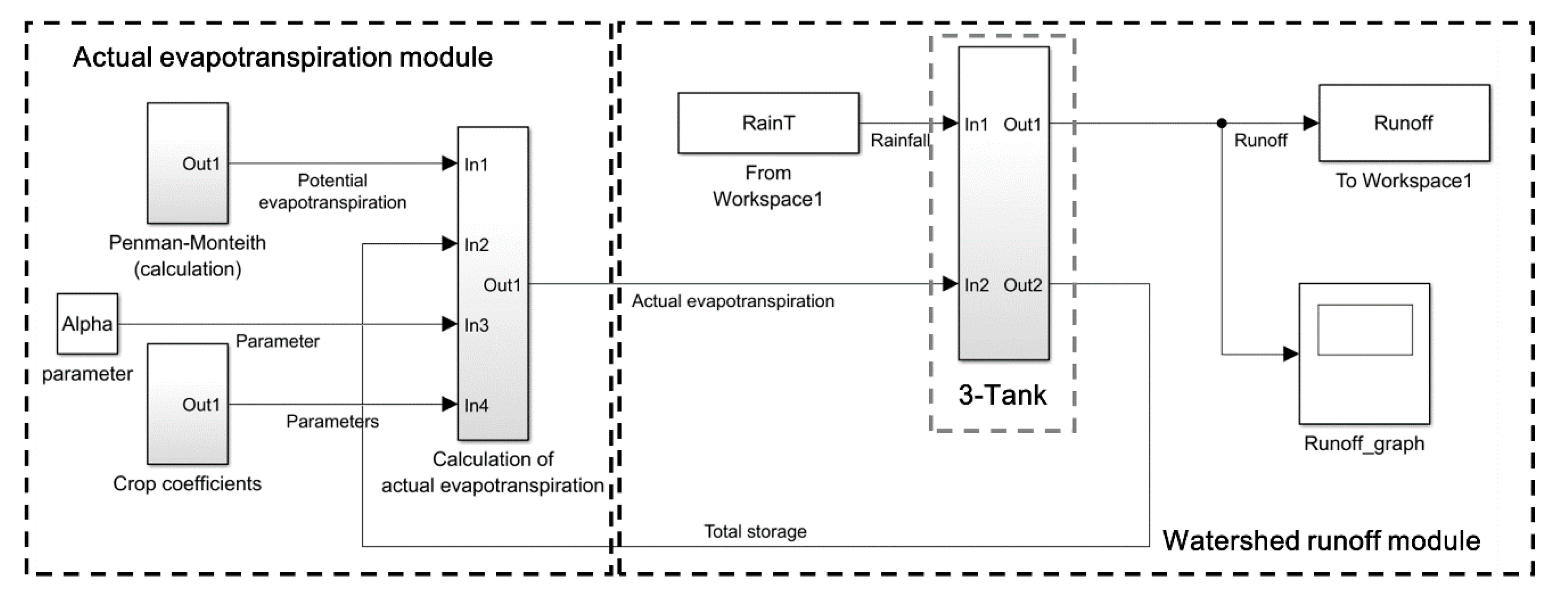
Figure 3 shows the results of the 3-Tank model developed using Simulink. The model consists of a watershed evapotranspiration module and a 3-Tank module. As shown in Figure 3, E T a is calculated based on E T p , K c , and K s , and then the results, along with rainfall observations, are used as input in the 3-Tank module. The output of the 3-Tank module consists of watershed runoff and storage. As shown in Equation (7), total storage is used as input data to calculate K s for the following day. The simulated results were exported through the “To Workspace” block to the MATLAB workspace, where the results could be analyzed using various embedded statistical methods and displayed in graph format using the “Scope” block. More detailed descriptions of the watershed evapotranspiration module and the 3-Tank module will be given in the following sections.

3.1. Watershed Evapotranspiration Module

Figure 4, which is a detailed illustration of the watershed evapotranspiration module introduced in Figure 3, shows the block connections needed to simulate E T a The watershed evapotranspiration module includes sections that calculate E T p (Figure 4a), K c (Figure 4b), and K s (Figure 4c), and a section that integrates these components to simulate E T a (Figure 4d).
The module inputs are comprised of: local climatic condition data, including temperature, humidity, and wind speed, which are loaded into the MATLAB workspace for the calculation of E T p ; land use area, which is employed in the computation of monthly K c ; and total water storage for the previous day simulated from the 3-Tank module, which is used in the calculation of K s . Then, the output of this module ( E T a ) is calculated using Equation (7) and used as input data for the 3-Tank model. The simulated results for E T p and E T a are exported to the MATLAB workspace and graphically displayed.
Although only the PM method was considered in this study for E T p simulation in a MATLAB/Simulink environment, it is also possible to use other methods, such as the Hargreaves equation, depending on the available data. The accuracy of streamflow simulation depends on E T p methods, so a more detailed explanation of this relationship can be found in [55]. Owing to the modular format of the Simlink-Tank, users can easily change E T p methods without changing the essential structure of the rainfall-runoff model.

3.2. 3-Tank Module

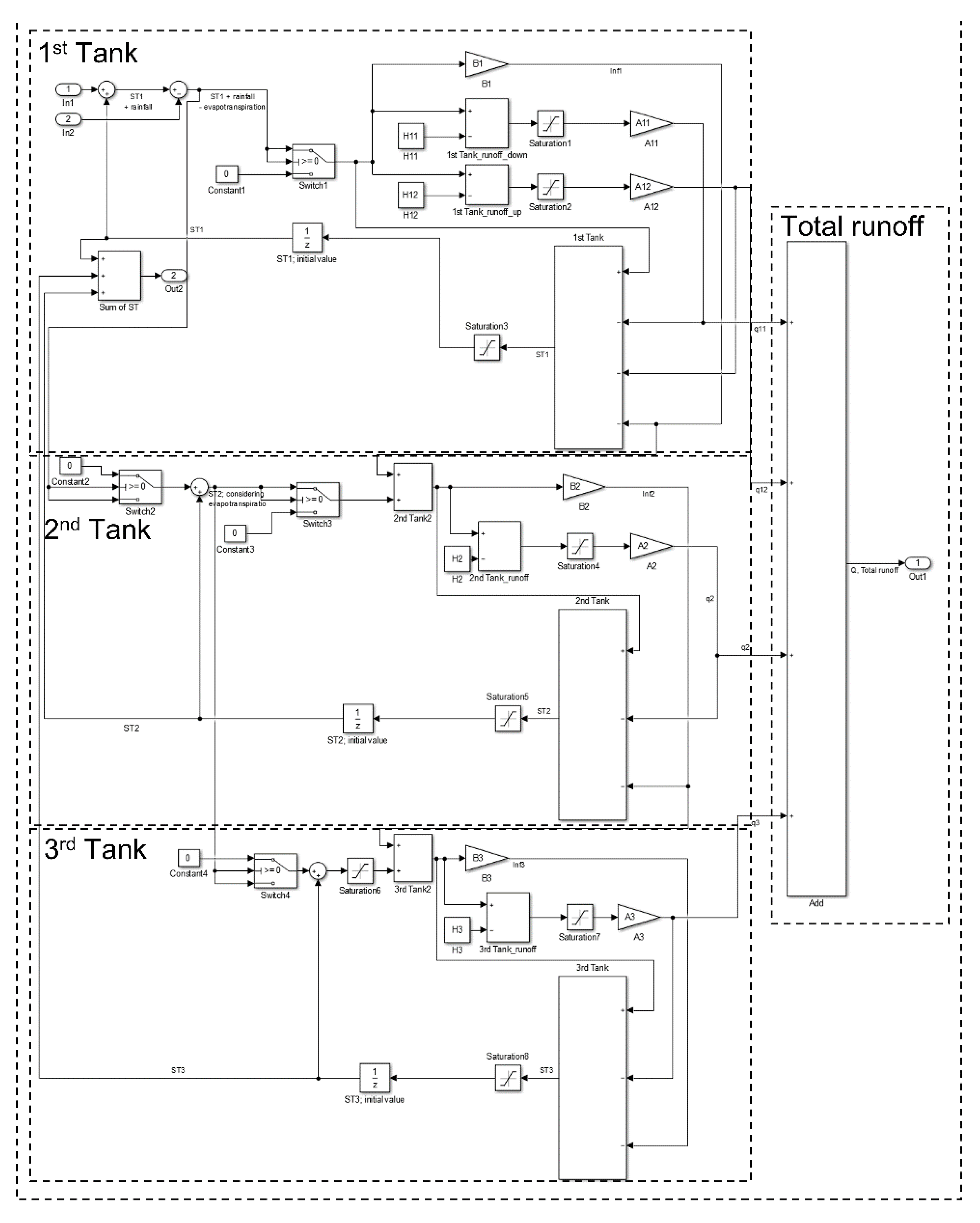
The structure of the 3-Tank module, which can be mathematically expressed by Equations (1)–(6), can also be portrayed using blocks connections in Simulink as shown in Figure 5. The input for the 3-Tank module includes rainfall observations and the E T a from the watershed evapotranspiration module. Rainfall is added into the first tank, while evapotranspiration is subtracted from the first tank. If there is no water in the first tank, evapotranspiration is subtracted from the second tank; if there is no water in both the first and second tanks, evapotranspiration is subtracted from the third tank (Figure 5). The storage of the first, second, and third tanks are calculated from rainfall, evapotranspiration, and infiltration, and the runoff for each tank is simulated using Equation (1). The total runoff for the watershed is calculated as the sum of the runoff from all tanks. As described in the previous section, infiltration is used as input data for simulating the storage for each tank for the following day, while total storage is used as input data for simulating K s .
The hydrologic modeling community has recently been introduced to the flexible module-based modeling approach. This approach does not attempt to develop a “one-size-fits-all” model structure but instead calls for the consideration of multiple working hypotheses for a given modeling application [56]. The modular approach enables the analysis of multiple structures and/or model components in order to find the combination that best approximates the relevant aspects of watershed behavior. The main advantage of this approach is the reduction of structural uncertainty, which results in more robust model applications [57]. We believe that the flexible modeling approach is best conducted in Simulink, owing to its block-based development environment and copy-and-paste user interface. The optimal structure of the tank model, such as the number of tanks and the number of outflows, can be changed depending on watershed characteristics. In Simulink-Tank, performing modeling considering uncertainty according to the structure of the model is convenient because the structure can be easily and flexibly changed by copying and pasting the block based on the model developed in Figure 5.

4. Case Study

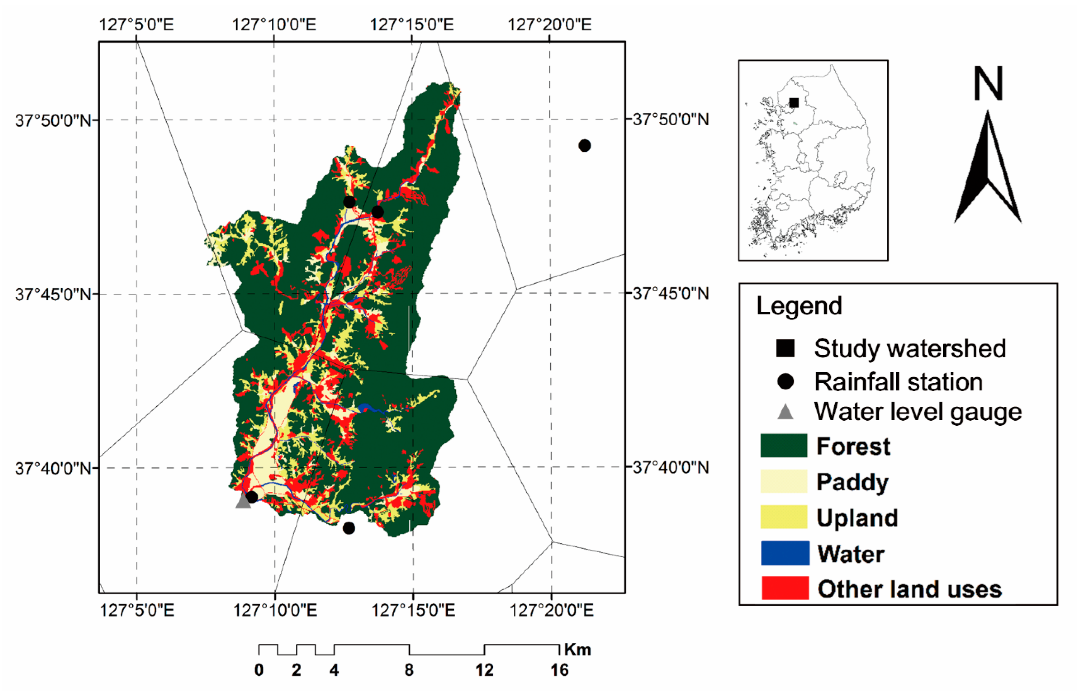
A case study was conducted for the Jinwangyo (JW) watershed in Korea to test the applicability of the Simulink-Tank (Figure 6). The study watershed is located near Seoul, Korea. The watershed area is 201.5 km2, of which 68%, 8%, 10%, and 14% is comprised of forest, paddy, upland, and other land uses, respectively.
Hourly precipitation data from 2004 to 2014 were obtained at five stations operated by the Ministry of Land, Infrastructure, and Transport (MOLTM), and the average hourly precipitation was determined using the Thiessen polygon method. Daily weather data, including temperature, relative humidity, mean wind velocity, and solar radiation, were obtained from the Dongducheon National Meteorological Station, which is the nearest station to the study area.
Water level observations were performed by MOLTM near the channel outlet of the study watershed. The measured water levels were converted to discharge using a water level–discharge relationship regressed from the measured data. The discharge data was divided into calibration and validation sets. A warm-up phase from 2004 to 2006 was used to achieve steady-state conditions in the model. According to [58,59], an ideal calibration period involves wet, average, and dry years. From this perspective, discharge data from 2011 to 2014 (i.e., 2011: wet year, 2012 to 2013: average years, and 2014: dry year) (Table 3) were selected for model calibration, and data from the other years (2007 to 2010) were used for model validation.

5. Application and Discussion of the Simulink-Tank Model

5.1. Dynamic Description of a Hydrologic System

Figure 7 shows the simulated results obtained from the Simulink-Tank model developed herein. In the Simulink modeling environment, dynamic changes in hydrologic components, including evapotranspiration, storage in each tank, and runoff in each tank, can be illustrated with a simple click. The Simulink-based model allows users to investigate the sensitivity of parameters influencing the hydrologic system. In addition, dynamic changes caused by structural changes in the model can be ascertained through a simple plug-and-play interface.
The advantages of the Simulink approach include increased model development speed, ease of optimization, inherent flexibility, transparency, and the ability to simulate interactions between the model components. It can save development and application time when more complicated structures are considered, since the extensive math and logic functions, visualization, and various toolboxes such as neural networks are already developed in block format and do not require additional programming to link them. Also, by facilitating the reuse of already developed blocks and modules with a copy-paste graphical interface, Simulink eliminates the need to write thousands of lines in codes. In addition, the process of conceptualization and mathematical representation of physical interactions among hydrologic components for the study watershed can be demonstrated in the Simulink-Tank. For example, users can ascertain the interaction between the evapotranspiration and the water storage visually with the related block: the more the evapotranspiration, the lesser the water storage, and consequently, the lesser the soil water stress coefficient ( K s ). This in turn decreases evapotranspiration, thereby completing the negative loop.
Despite these advantages, MATLAB/Simulink has two principal disadvantages. The first is that it is an interpreted language and therefore executes more slowly than compiled languages such as C or Fortran compilers. This problem can be mitigated by properly structuring the program to maximize the performance of vectorized code [60]. The second disadvantage is cost. However, this relatively high cost is amply offset by the reduced time required for an engineer to create a working program [60].

5.2. Parameter Calibration for the Simulink-Tank Model Using Optimization Techniques within MATLAB

Watershed models require calibration and validation to reduce the uncertainty of predictions [61,62]. Model calibration is usually accomplished either manually or using automatic procedures. In automatic calibrations, parameters are adjusted automatically according to a specific search scheme and numerical measures of the goodness-of-fit. Automatic calibration using various optimization techniques is faster than manual calibration and allows the confidence limits of the model simulations to be explicitly stated [63]. However, from a practical standpoint, programming inexperience can contribute to issues during the application of automatic optimization techniques even when the researchers are well versed in theory.
MATLAB has a graphical user interface (GUI)-based optimization toolbox that includes GA, SA, PS, and SCE-UA techniques as well as other optimization techniques, all of which are shared in an online community. Therefore, it is convenient to use the optimization routines within MATLAB for parameter calibration in the Simulink-Tank model; this also eliminates the need to build equivalent code. In this study, the Simulink-tank model parameters were calibrated using the SCE-UA approach in MATLAB.

5.2.1. Objective Function

The original Nash and Sutcliffe Efficiency ( N S E ) [64] and the root squared transformed N S E ( N S E s q r t ) [65] were used as objective functions for calibration, and compared as Case 1 and Case 2, respectively. The N S E emphasizes high flow due to the squared form, and the N S E s q r t provides more balanced information because the errors are more equally distributed between high- and low-flow components due to the root square transformed flow [65].
N S E = 1 [ i = 1 n ( O i P i ) 2 i = 1 n ( O i O ¯ ) 2 ]
N S E s q r t = 1 [ i = 1 n ( O i P i ) 2 i = 1 n ( O i O ¯ ) 2 ]
where O and P represent the observed and simulated discharge, respectively; n is the number of time steps at time step i ; and the over-bar represents an average of the given variable over the selected period.

5.2.2. Optimization Results

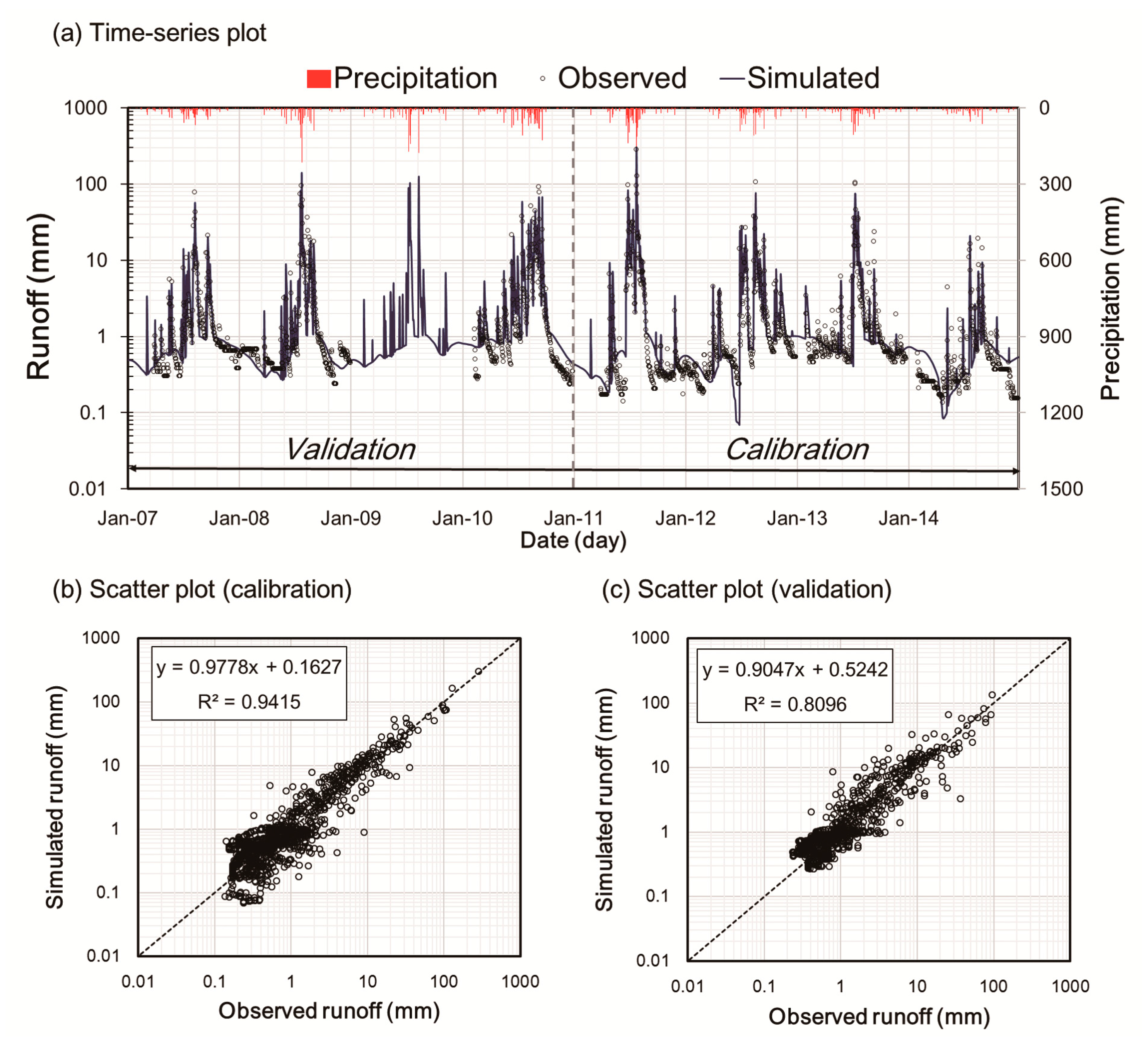
The Simulink-Tank model was calibrated for daily runoff automatically in the MATLAB environment. Both qualitative and quantitative measures were used for evaluating model performance. Graphical analyses, such as scatter and time-series plots, were used to identify general trends, potential sources of error, and differences between the measured and predicted values (Figure 8 and Figure 9). Quantitative criteria used to examine the feasibility of the model include: The coefficient of determination ( R 2 ) and the N S E , which are sensitive to peaks in discharge [57,66]; the Nash–Sutcliffe efficiency based on inverse discharge ( N S E i n v ), which emphasizes low flow errors [67]; and the percent bias ( P B I A S ) [62], which emphasizes errors in the water balance between observed and simulated runoff.
The graphical results during the calibration and validation periods indicated that the simulated runoff from Case 1 and Case 2 are similarly matched well with the observations (Figure 8 and Figure 9). Table 4 shows the results of a statistical comparison between the observed and simulated daily runoff for both of the cases. According to the NSE- and PBIAS-based assessments [62], the model’s performance is “very good” and “good”, respectively, for both of the cases. The values of N S E i n v during the calibration and validation periods were −0.15 and 0.34, respectively, for Case 1, and 0.07 and 0.57, respectively, for Case 2 (Table 4). The N S E i n v is the most useful criterion for evaluating very low flows [67], but there are no performance evaluation criteria for the index. Considering that N S E values between 0.0 and 1.0 indicate acceptable levels of performance [59], the simulated low flow results for Case 2 should be considered acceptable based on the N S E i n v assessment. For the case study watershed, calibrating with N S E s q r t yielded better low-flow simulation, and the results for high flows and water balance were still efficient.

6. Conclusions

This study introduced a modular Simulink-Tank model and applied the model to a rainfall-runoff analysis to demonstrate the utility and potential of a graphics-based model development environment, Simulink. The application results showed that the Simulink-Tank model could be conveniently developed and calibrated, and the calibration model provided acceptable performance in reproducing daily runoff hydrographs of the study watershed. The drag–drop graphical user interface of Simulink helped quickly understand the structure of a hydrologic model and the linkage between hydrologic components, and it also allowed for detailed descriptions of the sub-processes used, even as the main structure of the model remains unchanged. Moreover, various optimization methods provided by Simulink could be easily applied to parameter calibration without additional programming to link optimization algorithms to a model. The application of Simulink was limited to a Tank model in this study. However, the Simulink model development demonstrated here would be applicable to any rainfall-runoff models that represent hydrological components and processes with conceptual objects in simulation. In addition, users can easily customize a Simulink model by importing modules developed previously, since Simulink provides several functions to facilitate feedback and data transfer. Therefore, it is anticipated that Simulink will be widely used for hydrologic analysis as a variety of simulation needs are growing rapidly.

Acknowledgments

This work was carried out with the support of “Cooperative Research Program for Agriculture Science and Technology Development (Project No. PJ011686032017)” Rural Development Administration; Republic of Korea.

Author Contributions

Jung-Hun Song developed the model components and prepared the manuscript. Moon-Seong Kang supervised the research and revised the manuscript along with Younggu Her, Kyung-Do Lee, and Jihoon Park.

Conflicts of Interest

The authors declare no conflicts of interest.

References

  1. Singh, V.P.; Woolhiser, D.A. Mathematical modeling of watershed hydrology. J. Hydrol. Eng. 2002, 7, 270–292. [Google Scholar] [CrossRef]
  2. Kang, M.S.; Srivastava, P.; Song, J.H.; Park, J.; Her, Y.; Kim, S.M.; Song, I. Development of a Component-Based Modeling Framework for Agricultural Water-Resource Management. Water 2016, 8, 351. [Google Scholar] [CrossRef]
  3. Sugawara, M. Automatic calibration of the tank model. Hydrol. Sci. J. 1979, 24, 375–388. [Google Scholar] [CrossRef]
  4. Lindström, G.; Johansson, B.; Persson, M.; Gardelin, M.; Bergström, S. Development and test of the distributed HBV-96 hydrological model. J. Hydrol. 1997, 201, 272–288. [Google Scholar] [CrossRef]
  5. Moore, R.J. The probability-distributed principle and runoff production at point and basin scales. Hydrol. Sci. J. 1985, 30, 273–297. [Google Scholar] [CrossRef]
  6. Zhao, R.J. The Xinanjiang model applied in China. J. Hydrol. 1992, 135, 371–381. [Google Scholar] [CrossRef]
  7. Abbott, M.B.; Bathurst, J.C.; Cunge, J.A.; O’Connell, P.E.; Rasmussen, J. An introduction to the European Hydrological System—Systeme Hydrologique Europeen,“SHE”, 1: History and philosophy of a physically-based, distributed modelling system. J. Hydrol. 1986, 87, 45–59. [Google Scholar] [CrossRef]
  8. Young, R.A.; Onstad, C.A.; Bosch, D.D.; Anderson, W.P. AGNPS: A nonpoint-source pollution model for evaluating agricultural watersheds. J. Soil Water Conserv. 1989, 44, 168–173. [Google Scholar]
  9. Beasley, D.B.; Huggins, L.F.; Monke, A. ANSWERS: A model for watershed planning. Trans. ASAE 1980, 23, 938–0944. [Google Scholar] [CrossRef]
  10. Beven, K. Changing ideas in hydrology—The case of physically-based models. J. Hydrol. 1989, 105, 157–172. [Google Scholar] [CrossRef]
  11. Orth, R.; Staudinger, M.; Seneviratne, S.I.; Seibert, J.; Zappa, M. Does model performance improve with complexity? A case study with three hydrological models. J. Hydrol. 2015, 523, 147–159. [Google Scholar] [CrossRef] [Green Version]
  12. Gurtz, J.; Zappa, M.; Jasper, K.; Lang, H.; Verbunt, M.; Badoux, A.; Vitvar, T. A comparative study in modelling runoff and its components in two mountainous catchments. Hydrol. Process. 2003, 17, 297–311. [Google Scholar] [CrossRef]
  13. Kobierska, F.; Jonas, T.; Zappa, M.; Bavay, M.; Magnusson, J.; Bernasconi, S.M. Future runoff from a partly glacierized watershed in Central Switzerland: A two-model approach. Adv. Water Resour. 2013, 55, 204–214. [Google Scholar] [CrossRef]
  14. Khakbaz, B.; Imam, B.; Hsu, K.; Sorooshian, S. From lumped to distributed via semi-distributed: Calibration strategies for semi-distributed hydrologic models. J. Hydrol. 2012, 418, 61–77. [Google Scholar] [CrossRef]
  15. Rumbaugh, J.; Blaha, M.; Premerlani, W.; Eddy, F.; Lorensen, W. Object-Oriented Modeling and Design; Prentice-Hall: Upper Saddle River, NJ, USA, 1991. [Google Scholar]
  16. Argent, R.M.; Voinov, A.; Maxwell, T.; Cuddy, S.M.; Rahman, J.M.; Seaton, S.; Vertessy, R.A.; Braddock, R.D. Comparing modelling frameworks—A workshop approach. Environ. Model. Softw. 2006, 21, 895–910. [Google Scholar] [CrossRef]
  17. Clements, P.C. From subroutines to subsystems: Component-based software development. Am. Program. 1995, 8, 1–8. [Google Scholar]
  18. Zeigler, B.P. Object-Oriented Simulation with Hierarchical Modular Models; Academic Press: San Diego, CA, USA, 1990. [Google Scholar]
  19. Maxwell, T. A parsi-model approach to modular simulation. Environ. Model. Softw. 1999, 14, 511–517. [Google Scholar] [CrossRef]
  20. Muhanna, W.A. SYMMS: A model management system that supports model reuse, sharing, and integration. Eur. J. Oper. Res. 1994, 72, 214–243. [Google Scholar] [CrossRef]
  21. Guariso, G.; Hitz, M.; Werthner, H. An integrated simulation and optimization modelling environment for decision support. Decis. Support Syst. 1996, 16, 103–117. [Google Scholar] [CrossRef]
  22. Bennett, D.A. A framework for the integration of geographical information systems and model base management. Int. J. Geogr. Inf. Sci. 1997, 11, 337–357. [Google Scholar] [CrossRef]
  23. Reed, M.; Cuddy, S.M.; Rizzoli, A.E. A framework for modelling multiple resource management issues—An open modelling approach. Environ. Model. Softw. 1999, 14, 503–509. [Google Scholar] [CrossRef]
  24. Mantecón, J.A.; Gómez, M.; Rodellar, J. A Simulink-based scheme for simulation of irrigation canal control systems. Simulation 2002, 78, 485–493. [Google Scholar] [CrossRef]
  25. Kinnucan, P.; Mosterman, P.J. A graphical variant approach to object-oriented modeling of dynamic systems. In Proceedings of the 2007 Summer Computer Simulation Conference, Society for Computer Simulation International, San Diego, CA, USA, 16–19 July 2007. [Google Scholar]
  26. Bowen, J.D.; Perry, D.N.; Bell, C.D. Hydrologic and Water Quality Model Development Using Simulink. J. Mar. Sci. Eng. 2014, 2, 616–632. [Google Scholar] [CrossRef]
  27. Romanowicz, R. A Matlab implementation of TOPMODEL. Hydrol. Process. 1997, 11, 1115–1129. [Google Scholar] [CrossRef]
  28. Lanini, S.; Courtois, N.; Giraud, F.; Petit, V.; Rinaudo, J.D. Socio-hydrosystem modelling for integrated water-resources management-the Hėrault catchment case study, southern France. Environ. Model. Softw. 2004, 19, 1011–1019. [Google Scholar] [CrossRef]
  29. Chappell, N.A.; Tych, W.; Bonell, M. Development of the forSIM model to quantify positive and negative hydrological impacts of tropical reforestation. For. Ecol. Manag. 2007, 251, 52–64. [Google Scholar] [CrossRef]
  30. Wolfs, V.; Meert, P.; Willems, P. Modular conceptual modelling approach and software for river hydraulic simulations. Environ. Model. Softw. 2015, 71, 60–77. [Google Scholar] [CrossRef]
  31. MATLAB Documentation. Available online: mathworks.com/help (accessed on 9 March 2017).
  32. Paik, K.; Kim, J.H.; Kim, H.S.; Lee, D.R. A conceptual rainfall-runoff model considering seasonal variation. Hydrol. Process. 2005, 19, 3837–3850. [Google Scholar] [CrossRef]
  33. Jang, T.; Kim, H.; Kim, S.; Seong, C.; Park, S. Assessing irrigation water capacity of land use change in a data-scarce watershed of Korea. J. Irrig. Drain. Eng. 2011, 138, 445–454. [Google Scholar] [CrossRef]
  34. Fumikazu, N.; Toshisuke, M.; Yoshio, H.; Hiroshi, T.; Kimihito, N. Evaluation of water resources by snow storage using water balance and tank model method in the Tedori River basin of Japan. Paddy Water Environ. 2013, 11, 113–121. [Google Scholar] [CrossRef]
  35. Song, J.H.; Kang, M.S.; Song, I.; Jun, S.M. Water balance in irrigation reservoirs considering flood control and irrigation efficiency variation. J. Irrig. Drain Eng. 2016, 142, 04016003. [Google Scholar] [CrossRef]
  36. Wang, S.; Huang, G.H.; Baetz, B.W.; Ancell, B.C. Towards robust quantification and reduction of uncertainty in hydrologic predictions: Integration of particle Markov chain Monte Carlo and factorial polynomial chaos expansion. J. Hydrol. 2017, 548, 484–497. [Google Scholar] [CrossRef]
  37. Jung, D.; Choi, Y.H.; Kim, J.H. Multiobjective Automatic Parameter Calibration of a Hydrological Model. Water 2017, 9, 187. [Google Scholar] [CrossRef]
  38. Kim, H.Y.; Park, S.W. Simulating daily inflow and release rates for irrigation reservoirs. J. Korean Soc. Agric. Eng. 1988, 30, 50–62. (In Korean) [Google Scholar]
  39. Huh, Y.M. A Streamflow Network Model for Daily Water Supply and Demands on Small Watershed. Ph.D. Thesis, Seoul National University, Seoul, Korea, 1992. [Google Scholar]
  40. Schrader, F.; Durner, W.; Fank, J.; Gebler, S.; Pütz, T.; Hannes, M.; Wollschläger, U. Estimating precipitation and actual evapotranspiration from precision lysimeter measurements. Procedia Environ. Sci. 2013, 19, 543–552. [Google Scholar] [CrossRef]
  41. Rahimi, S.; Gholami, S.M.A.; Raeini-Sarjaz, M.; Valipour, M. Estimation of actual evapotranspiration by using MODIS images (a case study: Tajan catchment). Arch. Agron. Soil Sci. 2015, 61, 695–709. [Google Scholar] [CrossRef]
  42. Valipour, M. Comparative evaluation of radiation-based methods for estimation of potential evapotranspiration. J. Hydrol. Eng. 2014, 20, 04014068. [Google Scholar] [CrossRef]
  43. Thornthwaite, C.W. An approach toward a rational classification of climate. Geogr. Rev. 1948, 38, 55–94. [Google Scholar] [CrossRef]
  44. Blaney, H.F.; Criddle, W.D. Determining Consumptive Use and Irrigation Water Requirements; No. 1275; US Department of Agriculture: Washington, DC, USA, 1962.
  45. Jensen, M.E.; Haise, H.R. Estimating evapotranspiration from solar radiation. J. Irrig. Drain. Div. 1963, 89, 15–41. [Google Scholar]
  46. Hargreaves, G.H.; Samani, Z.A. Estimating potential evapotranspiration. J. Irrig. Drain. Div. 1982, 108, 225–230. [Google Scholar]
  47. Penman, H.L. Natural evaporation from open water, bare soil and grass. In Proceedings of the Royal Society of London, A: Mathematical, Physical, and Engineering Sciences, London, UK, 22 April 1948. [Google Scholar]
  48. Allen, R.G.; Pereira, L.S.; Raes, D.; Smith, M. Crop Evapotranspiration-Guidelines for Computing Crop Water Requirements-FAO Irrigation and Drainage Paper 56; Food and Agriculture Organization: Rome, Italy, 1998. [Google Scholar]
  49. Priestley, C.H.B.; Taylor, R.J. On the assessment of surface heat flux and evaporation using large-scale parameters. Mon. Weather Rev. 1972, 100, 81–92. [Google Scholar] [CrossRef]
  50. Yu, P.S.; Yang, T.C.; Chou, C.C. Effects of climate change on evapotranspiration from paddy fields in southern Taiwan. Clim. Chang. 2002, 54, 165–179. [Google Scholar] [CrossRef]
  51. Sung, S.H. Determination of Evapotranspiration Ratio to Estimate Actual Evapotranspiration in Small Forested-Watersheds. Master’s Thesis, Seoul National University, Seoul, Korea, 1997. (In Korean). [Google Scholar]
  52. Yoo, S.H.; Choi, J.Y.; Jang, M.W. Estimation of paddy rice crop coefficients for FAO Penman-Monteith and Modified Penman method. J. Korean Soc. Agric. Eng. 2006, 48, 13–23. (In Korean) [Google Scholar]
  53. Nonsaro. Available online: nongsaro.go.kr (accessed on 24 August 2017).
  54. Park, S.W. A Tank model shell program for simulating daily streamflow from small watershed. J. Korea Water Resour. Assoc. 1993, 26, 47–61. (In Korean) [Google Scholar]
  55. Oudin, L.; Hervieu, F.; Michel, C.; Perrin, C.; Andréassian, V.; Anctil, F.; Loumagne, C. Which potential evapotranspiration input for a lumped rainfall–runoff model? Part 2—Towards a simple and efficient potential evapotranspiration model for rainfall–runoff modelling. J. Hydrol. 2005, 303, 290–306. [Google Scholar] [CrossRef]
  56. Clark, M.P.; Kavetski, D.; Fenicia, F. Pursuing the method of multiple working hypotheses for hydrological modeling. Water Resour. Res. 2011, 47, 9. [Google Scholar] [CrossRef]
  57. Van Esse, W.; Perrin, C.; Booij, M.; Augustijn, D.; Fenicia, F.; Kavetski, D.; Lobligeois, F. The influence of conceptual model structure on model performance: A comparative study for 237 French catchments. Hydrol. Earth Syst. Sci. 2013, 17, 4227–4239. [Google Scholar] [CrossRef] [Green Version]
  58. Gan, T.Y.; Dlamini, E.M.; Biftu, G.F. Effects of model complexity and structure, data quality, and objective functions on hydrologic modeling. J. Hydrol. 1997, 192, 81–103. [Google Scholar] [CrossRef]
  59. Moriasi, D.N.; Arnold, J.G.; Van Liew, M.W.; Bingner, R.L.; Harmel, R.D.; Veith, T.L. Model evaluation guidelines for systematic quantification of accuracy in watershed simulations. Trans. ASABE 2007, 50, 885–900. [Google Scholar] [CrossRef]
  60. Chapman, S.J. MATLAB Programming for Engineers; Nelson Education: Scarborough, ON, Canada, 2015. [Google Scholar]
  61. Engel, B.; Storm, D.; White, M.; Arnold, J.; Arabi, M. A hydrologic/water quality model application protocol. J. Am. Water Resour. Assoc. 2007, 43, 1223–1236. [Google Scholar] [CrossRef]
  62. Moriasi, D.N.; Gitau, M.W.; Pai, N.; Daggupati, P. Hydrologic and water quality models: Performance measures and evaluation criteria. Trans. ASABE 2015, 58, 1763–1785. [Google Scholar] [CrossRef]
  63. Madsen, H. Automatic calibration of a conceptual rainfall–runoff model using multiple objectives. J. Hydrol. 2000, 235, 276–288. [Google Scholar] [CrossRef]
  64. Nash, J.; Sutcliffe, J.V. River flow forecasting through conceptual models part I-A discussion of principles. J. Hydrol. 1970, 10, 282–290. [Google Scholar] [CrossRef]
  65. Oudin, L.; Andreassian, V.; Mathevet, T.; Perrin, C.; Michel, C. Dynamic averaging of rainfall-runoff model simulations from complementary model parameterizations. Water Resour. Res. 2006, 42, 7. [Google Scholar] [CrossRef]
  66. Perrin, C.; Michel, C.; Andréassian, V. Improvement of a parsimonious model for streamflow simulation. J. Hydrol. 2003, 279, 275–289. [Google Scholar] [CrossRef]
  67. Pushpalatha, R.; Perrin, C.; Le Moine, N.; Andreassian, V. A review of efficiency criteria suitable for evaluating low-flow simulations. J. Hydrol. 2012, 420, 171–182. [Google Scholar] [CrossRef]
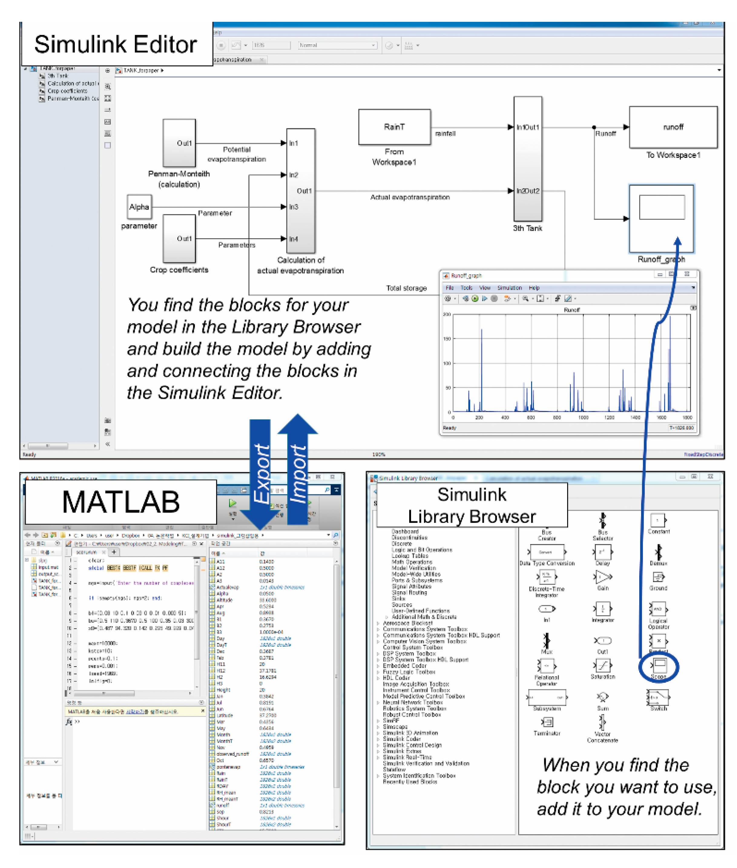
Figure 1. Modular modeling in the MATLAB/Simulink environment.
Water 09 00639 g001
Figure 2. Schematic of the modified Tank model [35].
Water 09 00639 g002
Figure 3. Schematic of the Simulink-based Tank model.
Water 09 00639 g003
Figure 4. Simulink scheme of the evapotranspiration module.
Water 09 00639 g004
Figure 5. Simulink scheme of the 3-Tank module.
Water 09 00639 g005
Figure 6. Land use and hydrologic measurement network in the case-study watershed.
Water 09 00639 g006
Figure 7. Dynamics in the Simulink-based Tank model developed herein.
Water 09 00639 g007
Figure 8. Comparison of observed and simulated runoff using (a) a time-series; (b) a scatter plot for the calibration period; (c) a scatter plot for the validation period (Case 1, objective function: N S E ).
Water 09 00639 g008
Figure 9. Comparison of observed and simulated runoff using (a) a time-series; (b) a scatter plot for the calibration period; (c) a scatter plot for the validation period (Case 2, objective function: N S E s q r t ).
Water 09 00639 g009
Table 1. Acceptable ranges of the modified Tank model parameters.
ParameterAlpha a 11 a 12 h 11 h 12 b 1 a 2 h 2 b 2 a 3 h 3 b 3
Min.00.080.085200.10.0300.010.00300
Max.0.50.50.5601100.50.51000.350.0300.11
Note: Constraint: h 11 < h 12 .
Table 2. Monthly crop coefficients for the four land-use types used with the FAO Penman–Monteith approach.
Crop Coeff.JanuaryFebruaryMarchAprilMayJuneJulyAugustSeptemberOctoberNovemberDecember
Forest0.470.460.550.590.740.720.871.010.980.870.640.45
Paddy0.200.200.200.650.700.991.301.170.830.200.200.20
Upland0.360.360.370.370.580.780.820.820.760.570.370.36
Others0.200.200.200.200.200.200.200.200.200.200.200.20
Table 3. Variation in yearly rainfall amount in the case-study watershed.
Year20072008200920102011201220132014
Rainfall (mm)1260145815411977221114811448767
Table 4. Model calibration and validation statistics. PBIAS: percent bias; NSE: Nash–Sutcliffe Efficiency.
CasePeriod R 2 N S E N S E i n v P B I A S (%)
1Calibration0.950.95−0.15−4.4
Validation0.800.790.34−7.5
2Calibration0.940.940.07−3.6
Validation0.810.800.57−7.3