1. Introduction
Estimating the environmental illumination information of a scene is important for improving the visual perception of a computer graphics (CG) augmented reality (AR) system. Environmental illumination information is used to render CG objects with coherent virtual shadows. Many methods have been introduced for generating the shadows of CG objects according to the light distribution of indoor and outdoor environments, enabling users to have a more realistic AR experience [
1,
2,
3,
4,
5,
6,
7,
8,
9,
10,
11,
12,
13,
14]. The goal of our study was to estimate the outdoor illumination information for a scene containing a human object.
Some methods employ illumination probes or imaging devices such as omnidirectional cameras and fish-eye lenses [
1,
2,
3,
4,
5]. These imaging devices must be radiometrically and geometrically calibrated, and they must be set up in advance. Methods have also been proposed for generating augmented rendering images with an environment map for an input video sequence [
1,
3]. However, these methods must perform elaborate light source sampling in the environment map to cope with unwanted lighting effects such as flickering. In addition, the environment map must be prefiltered to generate rendering images that reflect the surface reflectance properties of a virtual object.
In previous studies on the estimation of indoor illumination information [
6,
7,
8], it has been important to determine the sampling positions on the shadow surface. Therefore, three-dimensional (3D) model information about the object that casts shadows is required, and then a sampling strategy with which to choose the sample points on the shadow regions according to the object’s geometry.
Outdoor scenes are illuminated by light emitted mainly from the sun and sky [
4]. The position of the sun relative to the user’s location and orientation is computed as a directional light based on the geospatial position of the mobile device and the current date and time [
9]. However, if the user does not hold the mobile device at a suitable angle, the estimates can vary significantly. That means the method is highly affected by the angle-sensing capability of the mobile device.
A method has been presented to compute the probability distribution of the sun position from a single outdoor image [
10]. This method is based on a combination of weak scene cues such as the sky, vertical surfaces, ground, and convex objects in the image. A supervised learning approach is employed to segment scene elements, where a classifier is trained on features computed from a manually labelled dataset of images. Large numbers of images with annotated information are important for improving the illumination estimation performance. In addition, a convolutional-neural-network-based technique has been proposed for estimation of the high dynamic range of outdoor illumination from a single low-dynamic-range image [
5]. The method uses a physically based sky model—the Hošek–Wilkie model—in the convolutional neural network learning process. The sky model provides an accurate representation for clear skies, but its accuracy degrades when cloud cover increases.
Yanli et al. proposed a method for the online tracking of outdoor illumination variations from videos captured with moving cameras [
11]. Assuming that the scene consists of planar patches (ground and building surfaces), the method tracks only planar surfaces over the frames. Here, the scene was segmented using an estimated homography, but its performance was highly affected by scene elements such as complicated objects. In addition, to extract precise shadow regions, a more elaborate analysis of the color-based segmentation is needed [
12,
13].
In Reference [
14], a method using a time-lapse video to estimate the location of the sun in an outdoor environment was proposed. In this method, the user needs to specify in advance the 3D scene model that will cause the hard shadow boundary. It is assumed that there exists at least one appropriate hard ground shadow during the time-lapse video. More specifically, the method continues to track the edge features in the image with the 3D model of the object. Here, control points assigned by the user on the model edges are employed. This manual processing affects overall performance, and the specified shadow boundary may be occluded during a time-lapse video. Moreover, the scene elements such as surfaces (ground and building surfaces) must be manually labeled to estimate the illumination of outdoor videos [
15].
In this paper, we estimated the ground information and human objects using a stereo camera in an outdoor environment and computed the position of the sun using the geometric relationship of three scene elements: the ground, human object, and human-shadow region. In detail, to segment the foreground region (human object), a Gaussian mixture model (GMM)-based background learning method was applied to the 2D images and disparity map obtained by the stereo camera [
16]. Because the Kinect sensor, which is widely used to capture 3D information, cannot be used in outdoor environments, a stereo camera was employed. The v-disparity map was then used to analyze the scene element (ground surface) automatically [
17]. Using the geometric relationship of the three scene elements and the camera setup information (the shooting date, time, and location information obtained using a global positioning system (GPS)), we were able to estimate the azimuth and zenith angles of the sun. (We assumed that the main light source in outdoor environments is the sun.) The computed illumination information was used to render the virtual objects, which resulted in a visually convincing scene.
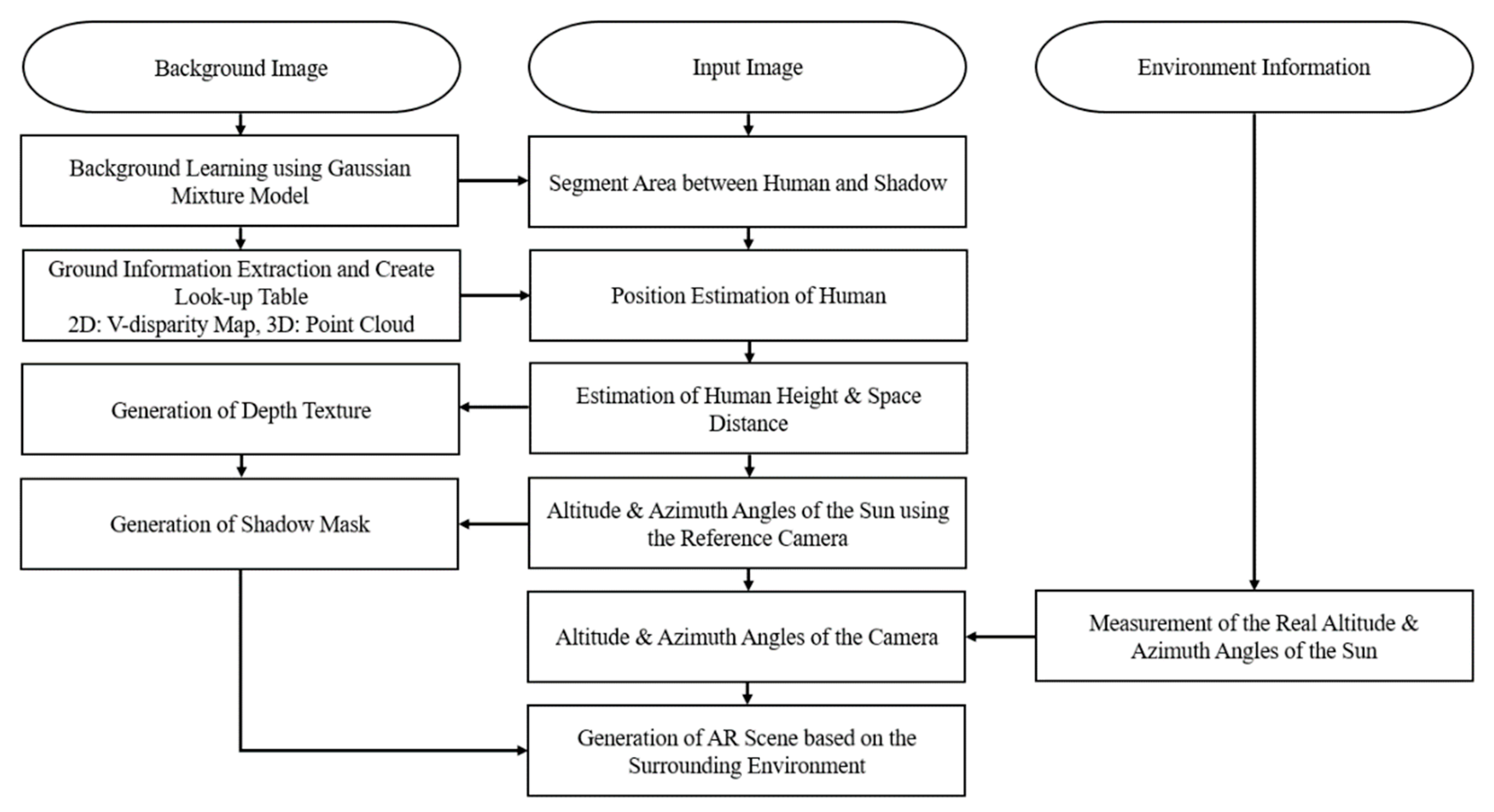
Figure 1 shows a flow chart of the proposed system.
This paper is organized as follows. In
Section 2, we describe the four steps in our system: segmenting the human object and the shadow regions, obtaining the relationship of scene elements, estimating the illumination information, and rendering shadow images with the environmental illumination. We then explain the experimental results in
Section 3 and conclude the paper in
Section 4.
2. Proposed Method
2.1. Human and Shadow Region Detection
The main illumination sources in outdoor environments are the sun and sky area [
4]. If a human object is standing in a sunlit outdoor environment, the shadow generated by the human object is located on the ground plane.
The background region of the scene, which is the region in which there is no foreground object, is learned in advance from an image sequence and a disparity map by the fixed stereo camera. In this paper, the initial 250 frames were used for GMM-based background learning. More specifically, each pixel value of the background in the reference image (left view) was represented by Gaussian models. When a human object appears in the scene, we were able to separate the foreground object from the background with the learned GMM information [
16]. In general, pixel-wise approaches like GMM tend to be affected by specific pixel properties. For example, if the value of a pixel of the human object is similar to that of the learned background, the performance is degraded. In addition, a change in the illumination distribution in the scene or a displacement of the background elements can generate foreground segmentation noise. To reduce the segmentation noise, we extracted the contours from the foreground region using the GMM. The region with the longest contour was determined to be the human object.
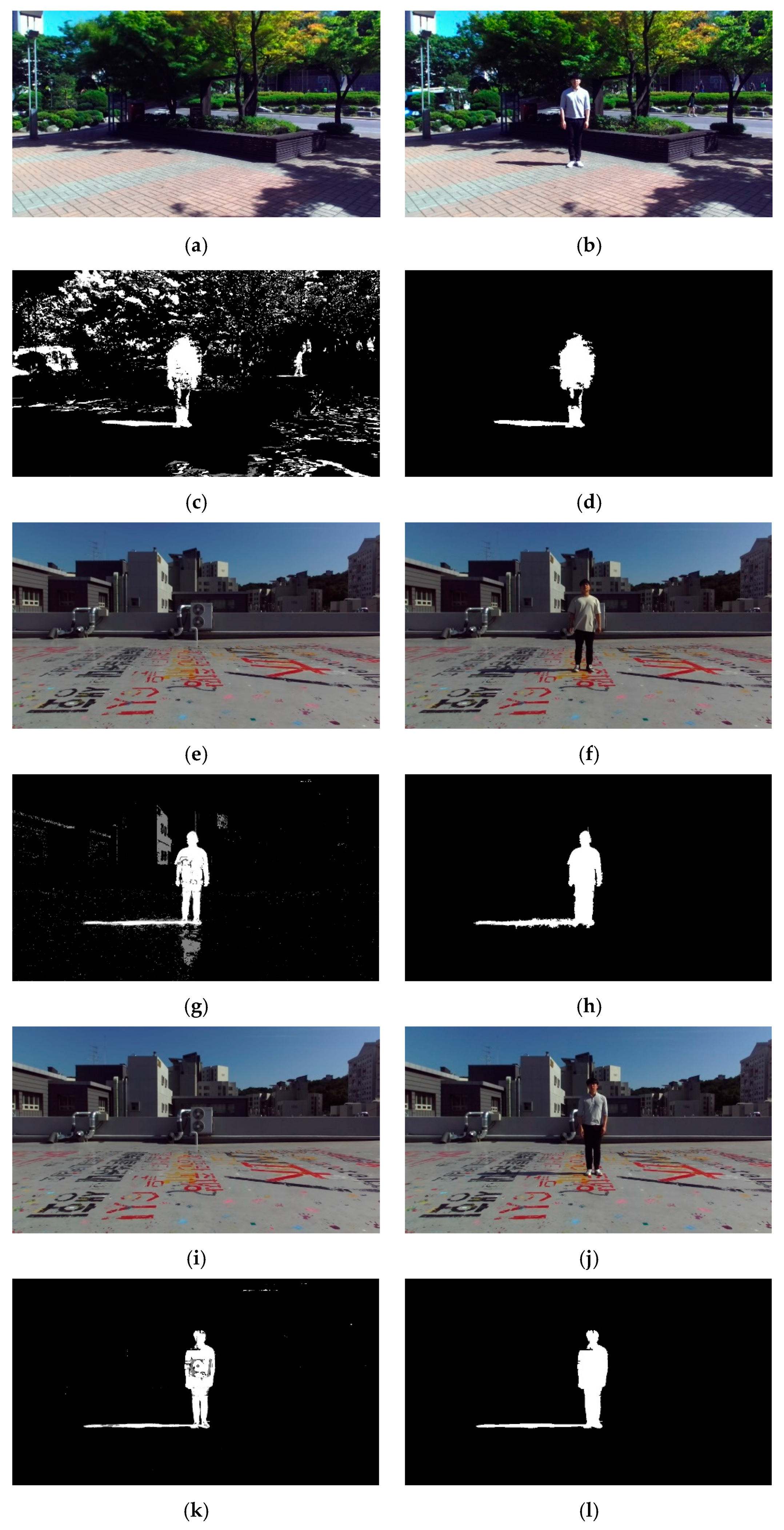
Figure 2 shows some example background images (
Figure 2a–c), input images with a human object (
Figure 2d–f)), the region obtained by the GMM (
Figure 2g–i), and the results of the noise removal (
Figure 2j–l).
Because sunlight is occluded by the human object, the color values of the shadow region on the ground are changed. To obtain the shadow region, the disparity maps (from stereo matching) were used in the GMM-based background. In the results obtained by the GMM, the human object was detected, but the shadow region was not labeled as a foreground object. Therefore, both the GMM results in the images and the disparity maps were used to segment the foreground region. Because the segmentation results obtained by the disparity map had unwanted noise artifacts, the depth values of the GMM-based background elements were used. More specifically, we examined whether the difference between the background depth information and the depth of the foreground object was equal to or below a certain threshold.
Figure 3 shows the segmentation results.
2.2. Three Feature Point Determination
The position information of the sun was computed using three feature points: the parietal (top) point of the human appearing in the scene, the parietal point of the shadow cast by the human, and the intersection point between the human and ground. When the human object is standing upright, we could accurately obtain the feature points. More specifically, the parietal point of the human is the highest point from the ground. The parietal point of the shadow is the farthest point from his or her feet on the ground. Therefore, this constraint of human posture makes the feature point determination procedure more precise.
The v-disparity map was computed by accumulating the pixels of the density disparity map in the horizontal direction [
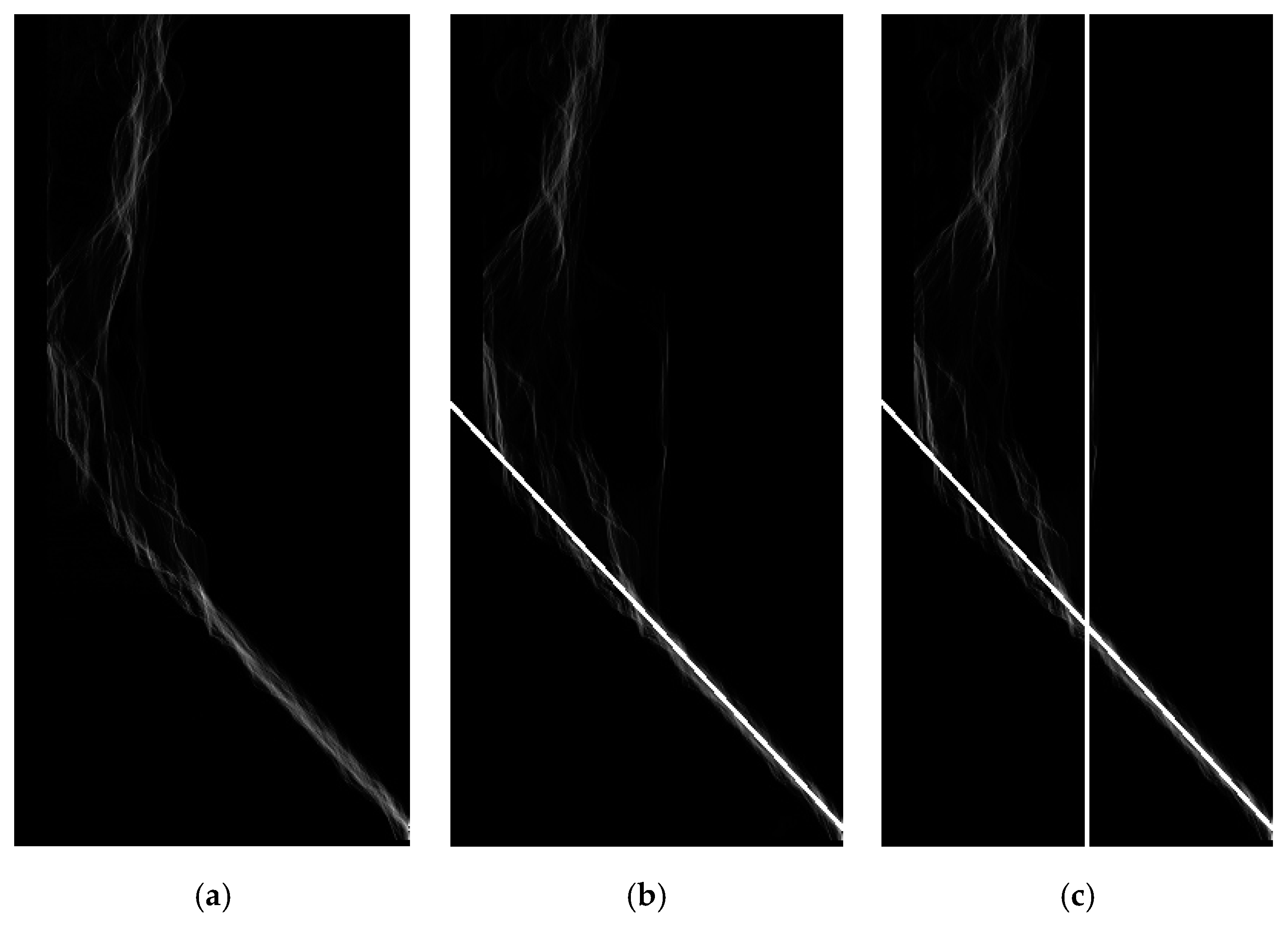
17]. A pixel (denoted P) on the v-disparity image has the coordinates (∆p, vp). The intensity of P equals the number of pixels on the line vp of the disparity map and has a disparity of ∆p. By accumulating the pixels of the disparity map, the v-disparity image is extremely robust with regard to the noise. The v-disparity image is generally used to extract the road plane and vertical obstacles. The v-disparity map of the background in sequence 1 (
Figure 4a) shows that the disparity values of the ground and the background were accumulated. To precisely estimate a line segment representing the ground, principal component analysis (PCA) was employed on the v-disparity map. The average values of the depth information about the background were computed over the 250 frames that were used in the background learning process. Here, random sample consensus (RANSAC) was applied to remove outliers. An equation for the straight line representing the ground was computed using the PCA vectors, as well as the average disparity values of the v-disparity map, as shown in
Figure 4b. The depth data corresponding to the ground plane were saved to a look-up table. This enabled us to access 3D depth data for each pixel in the ground region of the input image in real time.
As the human was assumed to be standing upright while facing the camera, we found the intersection point between the human and ground by vertically projecting the parietal point of the human to the ground. The disparity values of the human corresponded to the 3D depth of the human in the scene. In addition, the disparities varied over a range corresponding to the depth of his or her torso. There was a distinct disparity profile in the v-disparity map, and its column position represented the y-axis coordinate of the human location. More specifically, we computed the intersection point of the vertical straight line corresponding to the human with the straight line of the ground (
Figure 4c). Its y-axis coordinate was the location at which the person’s feet touched the ground. The x-axis coordinate of the human position was the highest point of the foreground contour obtained in the human detection process.
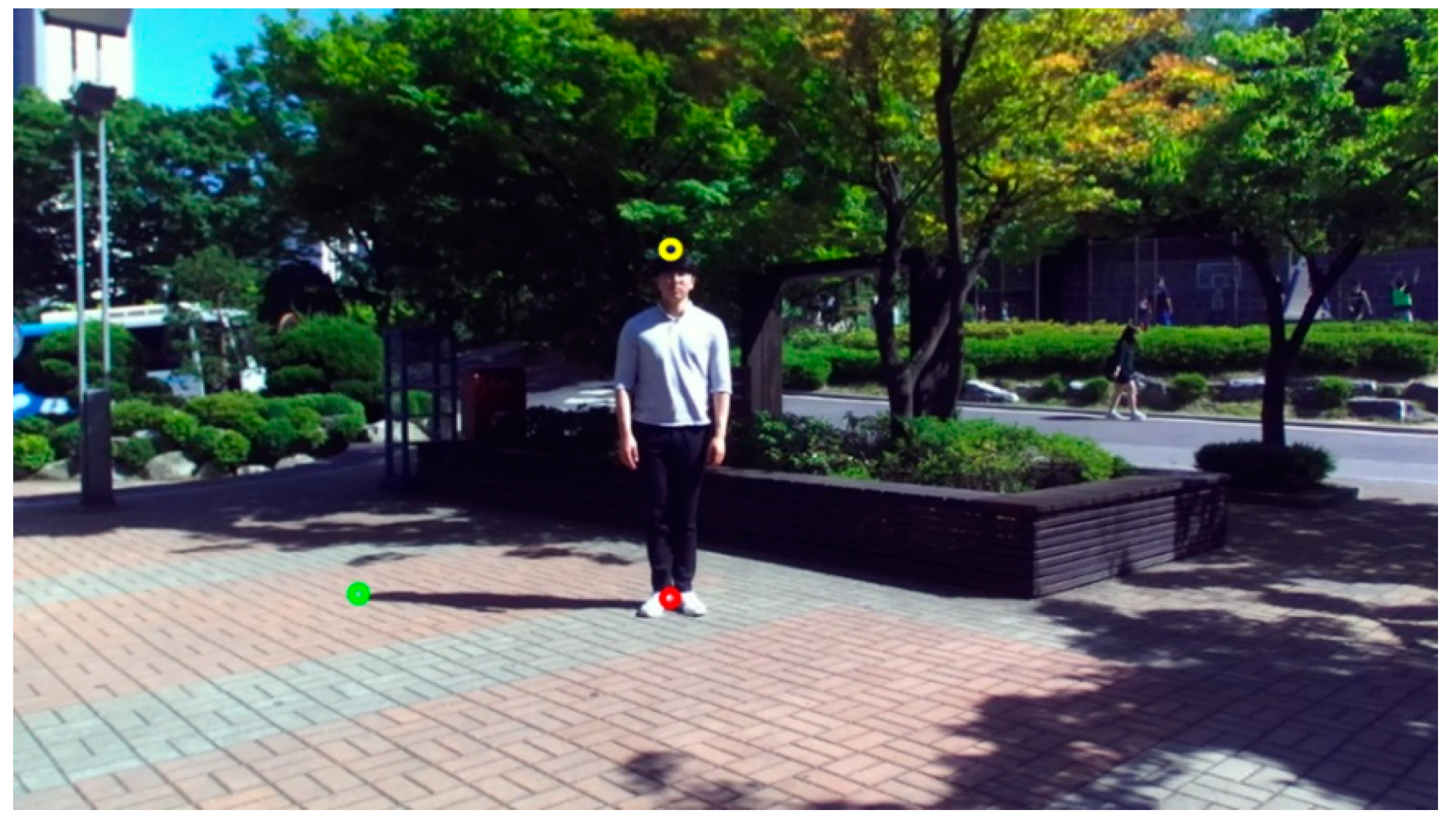
The feature point in the shadow region that corresponded to the parietal point of the human was the point that is farthest from the human’s feet. In other words, it was the farthest point from the intersection between the human and ground. The three feature points are illustrated in
Figure 5. The red circle indicates the location at which the human and the ground intersect. Green and yellow circles indicate the parietal points of the shadow and human, respectively. Using these three points, we describe how we computed the human height, as well as the altitude and azimuth angles of the sun with respect to the camera, in the next section.
2.3. Estimation of the Altitude and Azimuth Angles of the Sun
Using the relationship between the 3D depth value of the human object and the intrinsic parameters of the camera, such as the focal length and sensor size, we computed the height of the human object as follows.
where distance is the 3D depth of the human object with respect to the camera, height is the number of vertical pixels in the input image (resolution), and object height is the vertical length of the human region (the number of pixels). In addition, sensor height and focal length are the vertical length of the imaging sensor and the focal length of the camera, respectively.
In Equation (1), distance was determined to the median value of the 3D depth data in the human region, and object height the difference in the y-axis coordinates of the yellow and red circles in
Figure 5. In addition, sensor height and aspect ratio (width to height) were obtained from the camera specifications (55.329 mm and 16:9, respectively, for the ZED camera from Stereolabs Inc. San Francisco, CA, USA, used in this paper).
In the proposed method, the human height is used to estimate the altitude and azimuth angle of the sun. To compute the position of the sun with respect to the camera, previous methods employed the sun in the input image and its position in the world coordinate system [
18]. However, because the sun may not fall within the camera’s field of view, we used the three feature points and the height of the human object.
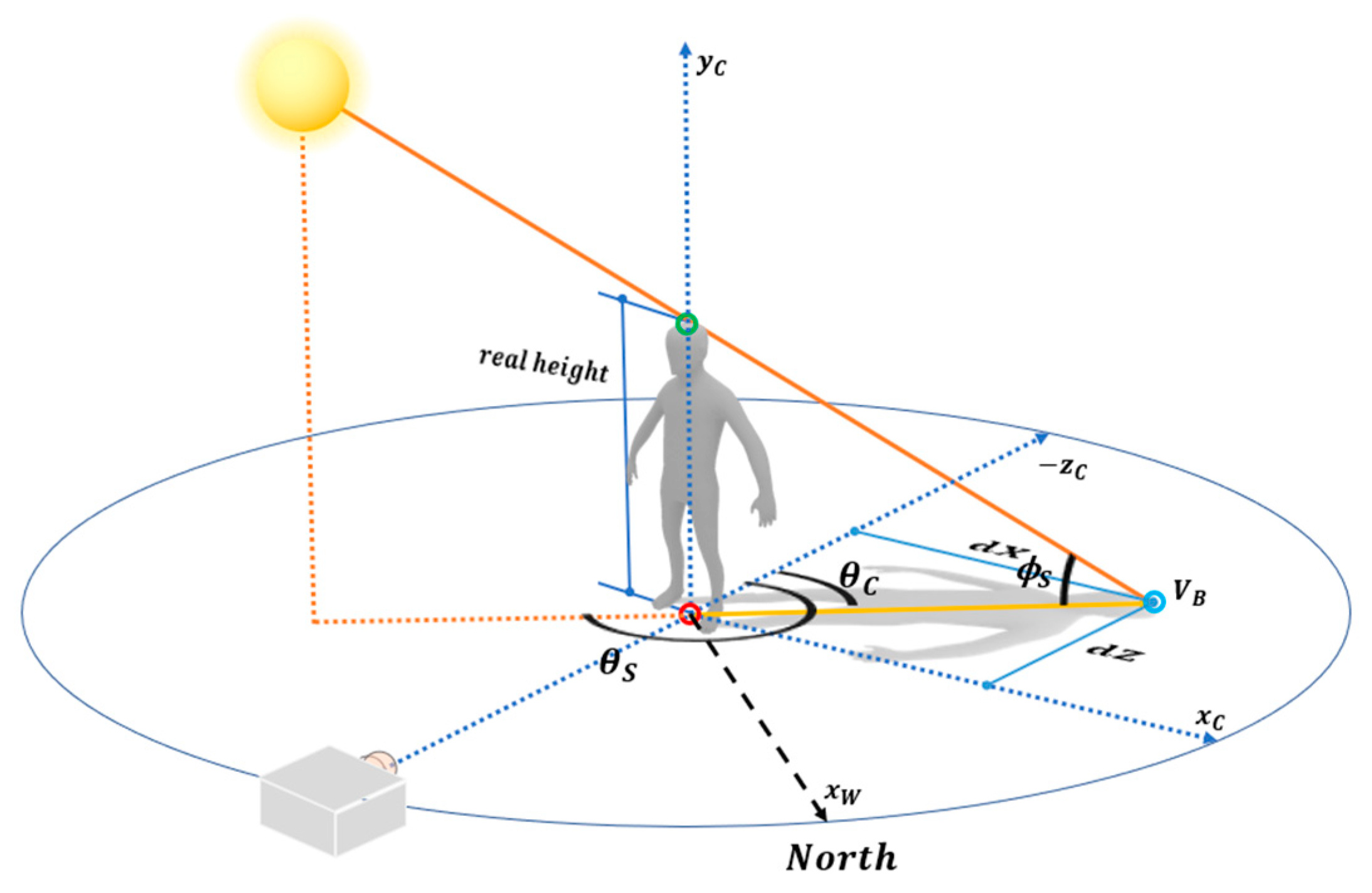
As shown in
Figure 6, the shadow of the human object is determined by the relationship between the human and sun. By extending the straight line connecting the parietal point of the shadow and with that of the human, we computed the position of the sun on the celestial sphere at an infinite distance. In this process, two triangles were generated from these scene elements: the straight line connecting the parietal points of the human and shadow, the vertical line connecting the sun and ground, and the vertical line of the parietal point of the human and the ground. The altitude of the sun was then computed using triangle similarity.
We used the coordinate values of the parietal point of the human and that of the shadow to compute the altitude
θS and azimuth
ϕS angles of the sun with respect to the camera. First, the camera coordinate system was transferred to the human coordinate system. Its origin was set to the interaction between the human and ground. The coordinate value of the human’s parietal point was obtained by adding the height of the human in the y-axis direction at the origin. The coordinate value of the shadow’s parietal point
VB is (
dX, 0,
dZ, 1), as shown in
Figure 6. Here,
dX and
dZ were easily computed by the distance from the origin, since vertex
VB and the origin were on the ground. In some cases, however, the 3D depth information of each feature point cannot be computed because of noise and occlusion on the ground. In this case,
dX can be computed using the following proportional expression, which is similar to the computation of the human’s height.
In addition,
dZ was obtained through the look-up table in
Section 2.2, since it is relative depth information based on the camera coordinate system. Angle
θC, which is the azimuth angle of the shadow vector (the yellow line segment in
Figure 6), was computed using the arctangents of
dX and
dZ, as follows.
More specifically, Equation (3) is divided into quadrants according to the location of the shadow, since the range of an arctangent is [−π/2, π/2]. The azimuth angle θS of the sun was computed by adding 180° to θC.
The altitude of the sun was computed by trigonometric functions on the triangle defined by the three feature points (
Figure 6). The altitude was computed using the human height and the length of the shadow vector as follows.
In this process, the altitude and azimuth angles of the sun with respect to the camera coordinates were computed. Hence, the sun information is dependent on the camera position. Therefore, using the difference of the altitude and azimuth angles of the sun in world coordinates and those of the sun in camera coordinates, we determined the altitude and azimuth angles of the camera [
19]. Because the camera was fixed so that it was horizontal with the ground, no further procedure was needed to compute the altitude angle in this case.
2.4. Rendering Using Environmental Illumination
For rendering a virtual object, we constructed the projection matrix of the CG camera using the following parameters: the focal length and principal point of the camera, the width and height of the screen, and the parameters of the far and near planes. In AR image rendering, the parameters of the CG camera were consistent with those of the stereo camera and 3D configuration in the scene.
The background (and ground) were learned before the 3D depth of the stereo camera was used. Three principal component vectors and the center point of the 3D data in the scene were computed by PCA. The method proposed herein assumes that the ground in the scene is a planar surface. Therefore, we constructed the world coordinate system of the scene by obtaining three basis vectors for the ground with respect to the camera. The three basis vectors represent the X, Y, and Z axes of the ground.
To construct the view matrix of the virtual camera, we determined four reference points on the ground using the relationships between two basis vectors. As the ground corresponds to the XZ plane (values in Y axis are zeros), we considered only two basis vectors in the X and Z axes. More specifically, based on the center point of the 3D data of the ground, we added the basis vector of the X axis and that of the Z axis with a scale factor (±0.5 m). Through this procedure, four reference points—((0.5, 0, 0.5), (−0.5, 0, 0.5), (−0.5, 0, −0.5), and (0.5, 0, −0.5)), making up a square on the ground—were determined. Subsequently, we constructed a camera matrix with the intrinsic parameters (focal length and principal point). We established the correspondence of the 3D coordinate values of the four reference points in the world coordinate system with the 2D image points obtained through the projection. Using this correspondence, the N-points algorithm computed the translation and rotation parameters of the camera so that the camera view matrix could be constructed [
20].
The virtual shadow cast by the CG object was generated using the depth texture with a frame buffer object in OpenGL [
21]. In general, because the light generated by the sun was implemented as directional light [
11], an illumination projection matrix was constructed with an orthogonal matrix. Using the view matrix of the directional light with the direction vector, we computed the relative depth information for the ground and the CG object. The occlusion regions of the two scene elements were considered in the rendering process. The unshadowed ground plane that was used in the background learning was examined to determine the illumination source intensity. If the ground plane was shadowed by the human object, there was a reduction in brightness. The change in brightness caused by a shadow in the same region was used to set the illumination source intensity in the scene, and Phong shading was employed.
To augment a scene with CG objects, any occlusion caused by another scene element such as a human object needs to be considered. Occlusion by the human object was generated by comparing the depth value of the human with the depth value of the rendered fragment.
3. Experimental Results
The experimental equipment comprised a PC with a 3.4 GHz CPU. The first three image sequences (sequences 1, 2, and 3) used herein were taken between 3:00 PM and 5:00 PM with the ZED stereo camera of Stereo-Labs. The second two image sequences (sequences 4 and 5) were taken between 11:00 AM and 1:30 PM. The GPS location of the experimental location was 126°57’E and 37°30’N. In general, the accuracy of the 3D depth information of the scene was affected by the stereo matching algorithm. In these experiments, we employed an open SDK library provided by the ZED stereo camera, which has real-time performance.
In our system, the stereo camera was employed to obtain depth information of the human object, ground, and the background. The Kinect sensor, which is widely used to capture 3D information, cannot be used in outdoor environments due to its IR sensing usage. The distance between the person and the stereo camera needs to be considerable enough to cover the human region from the head to the toe and the shadow generated by the human object. The human object also needs to be in the stereo camera’s depth range (for example, 20 m in the case of the ZED camera).
The disparity map of the human object and the background is generally affected by the illumination change and noise. To cope with the unwanted effects, the computed human height values were averaged for 100 frames. That means that the human object had to stand still for approximately three seconds. The mean error of the computed human height in the three image sequences was 1.35 cm. Here, the error was the average of the absolute difference between the ground truth and measured data. The experimental results confirmed that the precision in height estimation was affected by the segmentation results for the human region. Thus, more accurate segmentation of the human region will be investigated in future.
The altitude and azimuth angles computed by the proposed method were compared with the ground truth values. In our experiments, we computed the ground truth values (altitude and azimuth) of the sun using the method in Reference [
19]. The source code can be downloaded from the Solar Position Algorithm (SPA) homepage (
https://rredc.nrel.gov/solar/codesandalgorithms/spa/). An Android compass application was employed to evaluate the performance of accuracy. More specifically, the azimuth angle of the camera was measured using the Android compass application published by Melon Soft Co., Ltd. Using the orientation information of the camera, we transferred the altitude and the azimuth values computed by the proposed method to those in an absolute world coordinate system. Thus, we could compare the altitude and the azimuth values by the proposed method with the ground truth values listed in
Table 1. In addition,
Table 1 compares the ground truth for human height with the results obtained by the proposed method.
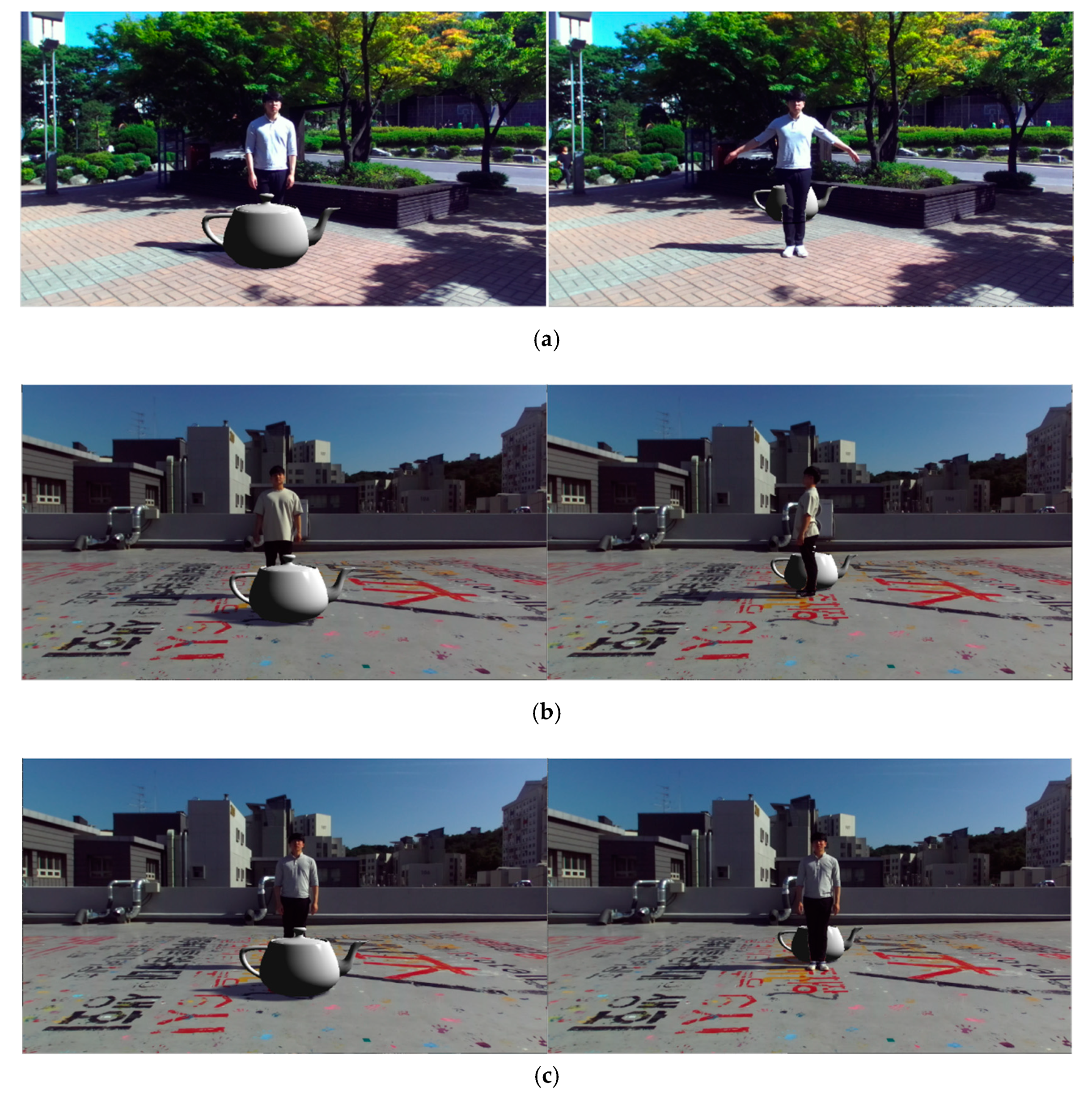
Figure 7 shows the AR images rendered using the environmental illumination information that includes the relative intensity and the altitude and azimuth angles of the sun in the scene. The left column in
Figure 7 shows the rendered images when the distance between the camera and the human object was larger than that between the camera and the CG object. In these images, the CG object occludes the human objects. The right column in
Figure 7 shows the rendered images when the human object occluded the CG object in the scene. The experimental results show that the disparity map of the human object can be used as a matte for compositing in real time.
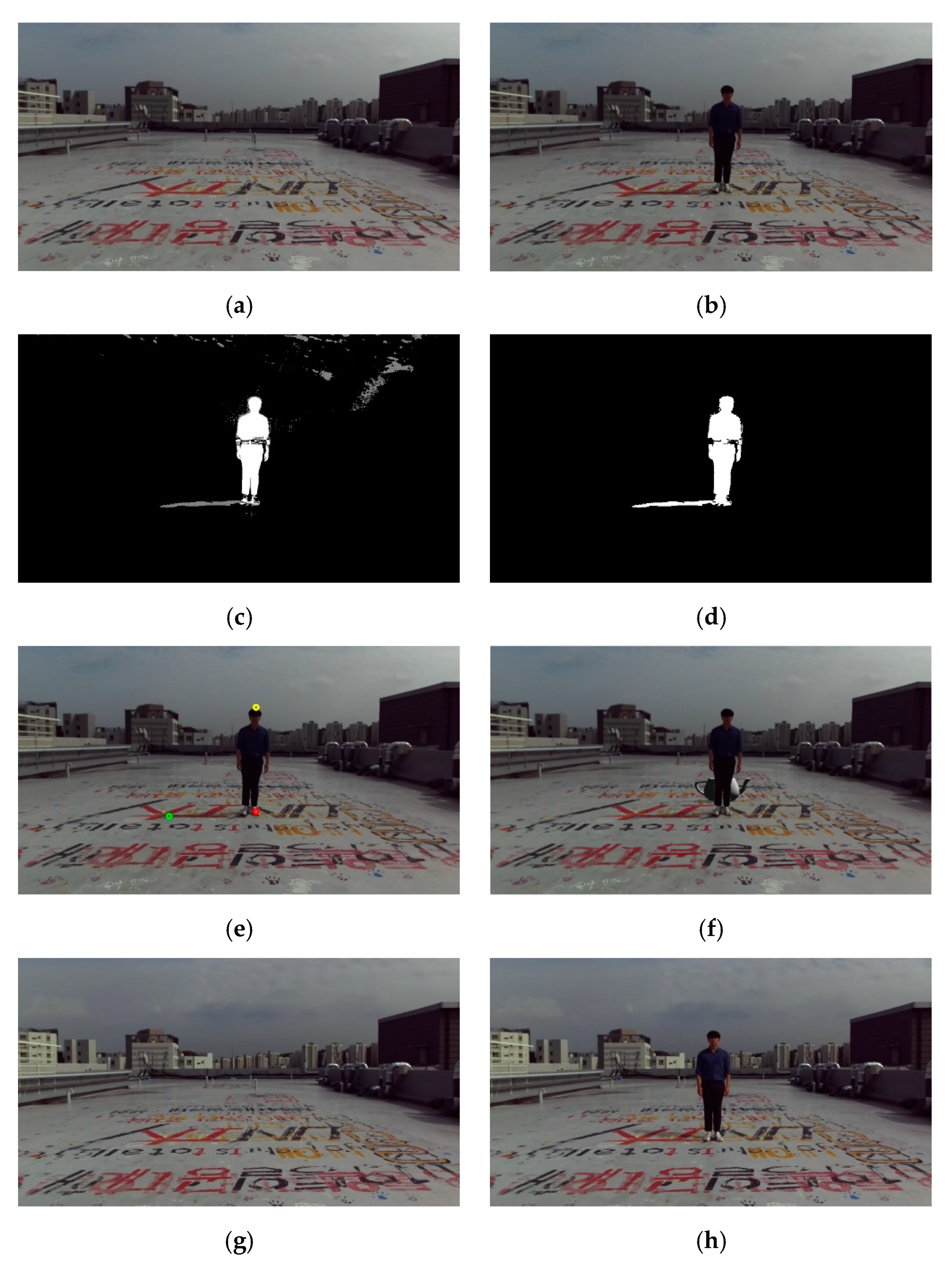
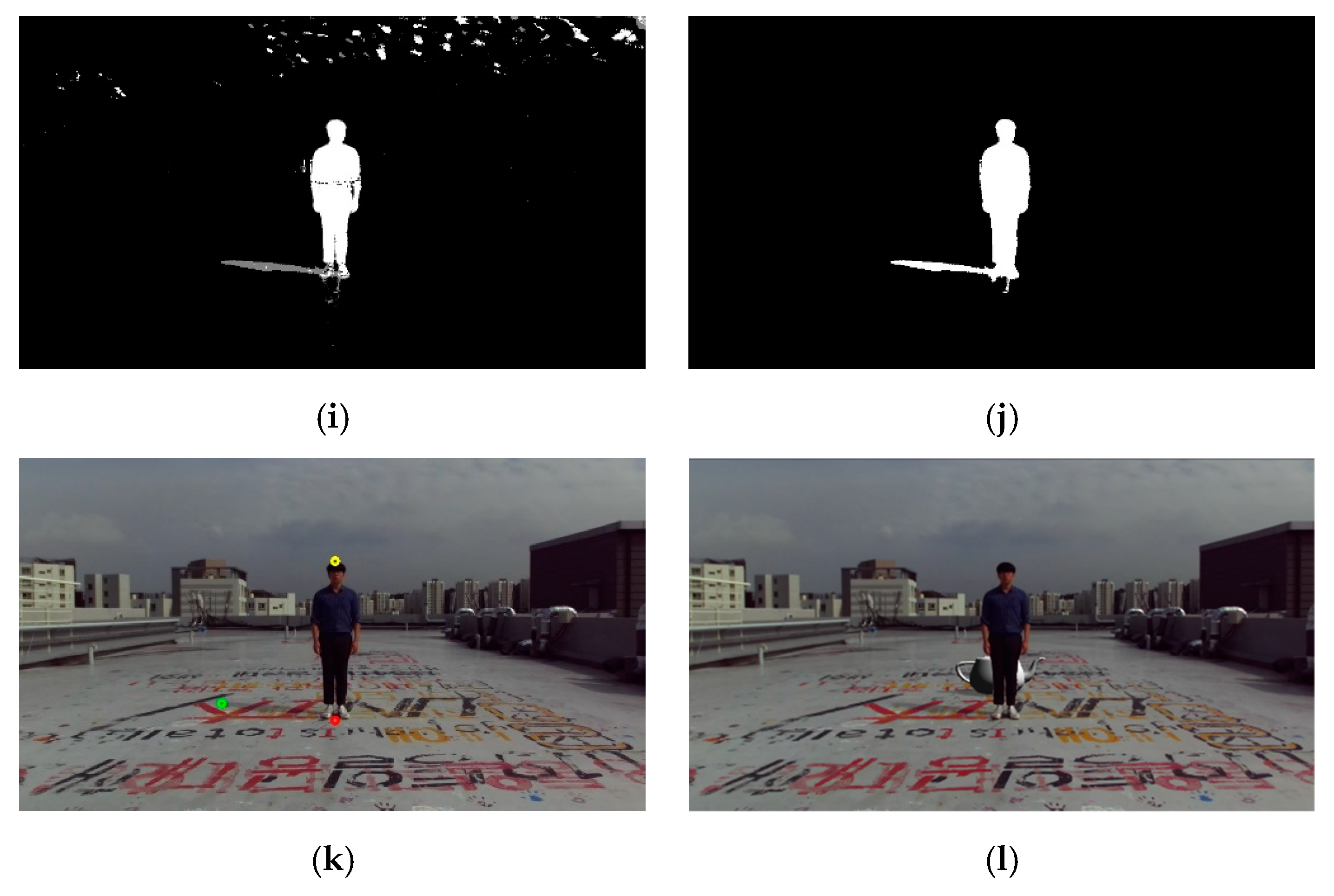
The second two image sequences (sequences 4 and 5) were captured in the same place but at different times (between 11:00 AM and 1:30 PM). The shadows made by the human object were much changed from morning to afternoon. Among the three feature points used to estimate the position information of the sun, only the parietal point of the shadow was dependent on the size and shape of the shadow. To precisely estimate the position information of the sun, the condition that the parietal point of the shadow is the farthest point from his or her feet on the ground must be satisfied. In general, a person’s shadow becomes relatively short near noon. That means that specifying the parietal point of the shadow on the ground is difficult. However, these two image sequences show that shadows with enough size and shape were generated on the ground.
Figure 8 shows the background and input images and the experimental results from sequence 4 and 5.
Table 2 shows the results of human height as well as the azimuth and altitude angles of the sun for image sequences 4 and 5. For a special case such as summer solstice, a user input to determine the parietal point of the shadow would be needed.
The method proposed in this paper has some limitations. In this paper, we assumed that the target scene had a flat surface on which a sufficient shadow could be generated by the human object. Therefore, when the shape of the ground plane is uneven or its reflectance property is too high, the proposed method would find it difficult to obtain accurate results. Because the background learning and foreground segmentation were performed by the GMM method, the performance was affected in two cases: when the illumination distribution rapidly changed, and when the background and the target object had the same color distribution. Finally, the human object segmentation performances were dependent on the stereo matching algorithms.


